92
The 2015 Audi A3 Introduction eSelf Study Program 990143

The 2015 Audi A3 Introduction
eSelf Study Program 990143

3
Audi of America, LLC Service Training Created in the U.S.A. Created 11/2013 Course Number 990143
©2013 Audi of America, LLC
All rights reserved. Information contained in this manual is based on the latest information available at the time of printing and is subject to the copyright and other intellectual property rights of Audi of America, LLC., its affiliated companies and its licensors. All rights are reserved to make changes at any time without notice. No part of this document may be reproduced, stored in a retrieval system, or transmitted in any form or by any means, electronic, mechanical, photocopying, recording or otherwise, nor may these materials be modified or reposted to other sites without the prior expressed written permission of the publisher.
All requests for permission to copy and redistribute information should be referred to Audi of America, LLC.
Always check Technical Bulletins and the latest electronic service repair literature for information that may supersede any information included in this booklet.
Revision 4: 12/2013

4
Introduction ................................................................................................6
The A3 sedan body ......................................................................................7Dimensions .............................................................................................................................................................. 7Vehicle architecture (MQB) ..................................................................................................................................... 9MQB and the Audi A3 .............................................................................................................................................. 9Materials - ultra lightweight construction ......................................................................................................... 11Body panels ........................................................................................................................................................... 13Joining techniques ................................................................................................................................................ 13Panorama tilt sunroof .......................................................................................................................................... 16Bumper system ..................................................................................................................................................... 18Underbody ............................................................................................................................................................. 18
Passive safety ............................................................................................19Components .......................................................................................................................................................... 19System overview ................................................................................................................................................... 20Vehicle Airbags ...................................................................................................................................................... 21Front safety belt tensioner .................................................................................................................................. 26Pelvic belt tensioner with locking buckle ........................................................................................................... 27
Active Safety ..............................................................................................31Audi pre sense ....................................................................................................................................................... 31
Engines ......................................................................................................371.8L and 2.0L TFSI engines .................................................................................................................................. 37Diesel engines ....................................................................................................................................................... 39Engine/transmission combinations .................................................................................................................... 41
Power transmission ...................................................................................43Overview ................................................................................................................................................................ 435th generation Haldex coupling .......................................................................................................................... 45Transmission selector mechanism ...................................................................................................................... 52
Fuel tanks ..................................................................................................53Exhaust system ..................................................................................................................................................... 54
Running gear .............................................................................................55Design concept ...................................................................................................................................................... 55Suspension variations .......................................................................................................................................... 57Tire Pressure Monitoring System ........................................................................................................................ 57Wheels and tires ................................................................................................................................................... 58
Electrical system .......................................................................................59Audi drive select .................................................................................................................................................... 59Installation locations of control modules .......................................................................................................... 61Topology ................................................................................................................................................................ 63
Climate control ..........................................................................................65Introduction .......................................................................................................................................................... 65Connected components ....................................................................................................................................... 67Connected components ....................................................................................................................................... 68
Infotainment .............................................................................................69Overview of versions ............................................................................................................................................. 69Standard MIB ........................................................................................................................................................ 72High spec MIB with navigation ............................................................................................................................ 73Multimedia System Control Head E380 .............................................................................................................. 75MMI display ........................................................................................................................................................... 76
Contents

5
This eSSP contains video links which you
can use to access interactive media.
Audi Connect .............................................................................................77Overview ................................................................................................................................................................ 77LTE .......................................................................................................................................................................... 78Antenna overview ................................................................................................................................................. 81LTE antennas ......................................................................................................................................................... 83Sound systems ...................................................................................................................................................... 85
Service .......................................................................................................87Service interval overview for North American region ........................................................................................ 87Special tools and workshop equipment ............................................................................................................. 88
Self Study Program ...................................................................................91
Knowledge Assessment ............................................................................92
This eSelf Study Program teaches a basic knowledge of the design and functions of new models, new automotive components or technologies. It is not a Repair Manual! All values given are intended as a guideline only. For maintenance and repair work, always refer to the current technical literature.
Note
Reference
Contents

6
The Audi A3 can look back on a 16-year success story. The first generation of the series, which debuted in 1996 as a three door, established an entirely new market segment – the premium compact class. In 1999 the five-door hatch-back and the sporty Audi S3 completed the family. In total, around 990,000 vehicles were sold. The second generation, launched in 2003, was even more successful, achieving sales of approximately 1.8 million vehicles.
With the newest generation of the A3, the Group has set itself the goal of improving the fuel economy of its internal combustion engines, extending its product range to include alternative drive systems such as natural gas engines and electric motors, and equipping the vehicles with the latest technical innovations. The basis for implementing these objectives is the MQB or “modular transverse platform”, a standardized architecture in which various vehicle compo-nents can be combined in any configuration on modular principles. This broadens the diversity of the model range, resulting in more efficient production, engines and combi-nations of materials.
The 2015 A3 sedan represents the cumulative technologi-cal expertise of Audi in a compact format. In its lightweight body, its interior architecture and its user interfaces, the A3 sedan will once again set standards in its class. Its engines impress with their efficiency and power, and the range of driver assistance systems and infotainment solutions is unparalleled in the premium compact class.
625_001
The lightweight body and newly developed engines have had major consequential effects throughout the vehicle, reducing the weight of many suspension, exhaust and interior components. At launch, the vehicle will be offered with two recently refined engines from the EA888 family. The Modular Infotainment Platform (MIB) makes its debut in the A3 sedan. It represents a big step forward in mobile communication electronics.
The A3 also sets new standards in the premium compact class when it comes to driver assistance systems. One of the most important of these is Audi pre sense. In the event of an impending collision, the system warns the driver in progressive stages and, if necessary, can initiate partial braking in order to reduce the car’s speed at impact.
The Audi A3 and S3 sedans are assembled in Györ, Hungary.The site in northwestern Hungary is one of the largest automobile factories in the world. This is where Audi has assembled the TT coupe, and in the near future will assem-ble the A3 cabriolet. It is an ultra modern facility with the capability of complete production work—from stamping to final assembly.
Introduction

7
61.2 in (1555 mm) 60.0 in (1526 mm)
70.7 in (1796 mm)
37.0 in (942 mm)
39.6
in (1
006
mm
)
36.3
(924
mm
)
37.4 in (950 mm)
175.4 in (4456 mm)
34.2 in (869 mm)
27
.0 in
(68
8 m
m)
77.1 in (1960 mm)
55
.7 in
(1
41
6 m
m)
103.8 in (2637 mm)
Dimensions
625_038
625_036 625_037
The A3 sedan body

8
37.4 in (951 mm)
39
.3 in
(1
00
0 m
m)
54
.8 in
(1
39
2 m
m)
57
.2 in
(1
45
3 m
m)
52
.9 in
(1
34
5 m
m)
56
.0 in
(1
42
3 m
m)
Dimensions and weight
Length 175.4 in (4456 mm) Front elbow room 57.2 in (1453 mm)
Width 70.7 in (1796 mm) Rear elbow room 56.0 in (1423 mm)
Height 55.7 in (1416 mm) Front head room 39.6 in (1006 mm)
Front track width 61.2 in (1555 mm) Rear head room 36.3 (924 mm)
Rear track width 60.0 in (1526 mm) Load pass-through width 39.3 in (1000 mm)
Wheelbase 103.8 in (2637 mm) Load lift-over height 27.0 in (688 mm)
Luggage compartment volume 15.0/31 1) cu ft (425/880 1) l)
Curb weight (approximate) 2899.0 lb (1325 kg)
Permissible total vehicle weight 4111.6 (1865 kg)
625_039
1) Rear seat folded
A3 sedan compared to A4 sedan

9
Vehicle architecture (MQB)
The Audi A3 sedan builds on the body structure of the three-door A3. It is part of the MQB strategy used by the Volkswagen Group of which Audi is a part. MQB stands for modular transverse baukasten or modular transverse platform.
It is not so much a platform per-se, but rather a system for introducing commonality across disparate platforms that share the same engine orientation — regardless of model,
MQB and the Audi A3
The underbody of the A3 series consists of 3 modules:
• the front section • Floor pan, center section• Trunk floor
Compared to the three-door A3, the A3 sedan needed a longer central floor pan and a longer rear floor pan but are based on the same basic design and manufacturing pro-cesses.
625_118
Variable VariableUniform Longer overhang + 6.4 in (165 mm)
Wheelbase + 1.37 in (35 mm)
625_119
vehicle size or brand. MQB uses a core group of components across a wide variety of platforms — for example, sharing a common engine-mounting for all drivetrains. The concept allows diverse models, including those from the company‘s various brands, to be manufactured at the same plant, further saving cost.

10
Notes

11
Materials - ultra lightweight construction
Body developers at Audi have broad-based engineering expertise spanning all relevant materials. This know-how is not limited to just a specific material, rather the motto is: “The right material at the right place for optimal function.” The multi-material body of the Audi A3 lives up to this maxim.
Ultra high-strength hot-formed steel components
Ultra high-strength hot-formed steel components provide approximately a 24% share of the A3 sedan body structure. Before the components are stamped, special steel is heated to nearly 1832 °F (1000 °C) in a continuous oven. After heating, it is immediately placed in a water cooled press tool. The steel is quickly cooled to approximately 392 °F (200 °C) before it is stamped. The rapid cooling of the steel changes its iron/carbon structure and creates a steel with high tensile strength which in turn allows thinner wall thicknesses for the particular components. Steels created in this manner require special care and procedures during repairs.
All the ultra lightweight design principles that have made all A3 models lighter than their predecessors have been applied to the design of the new A3 sedan.
At the same time, the A3 sedan meets the highest demands in the area of vehicle safety. The basis for this is that only materials used are those that meet the high quality standards of Audi.

12
625_109
A3 sedan B pillar
The B-pillar with striker plate is partially tempered during the forming process. The component assembly is very hard at the top end and softer below a narrow transition zone. This enables side impact forces to be absorbed effectively.
625_110
High-strength steel 30%
Soft steel 28.5%
Aluminum 0.5%Modern high-strength steel 17%
Ultra high-strength hot-formed steel 24%
625_111
Ultra high-strength
Ultra high-strength
High-strength

13
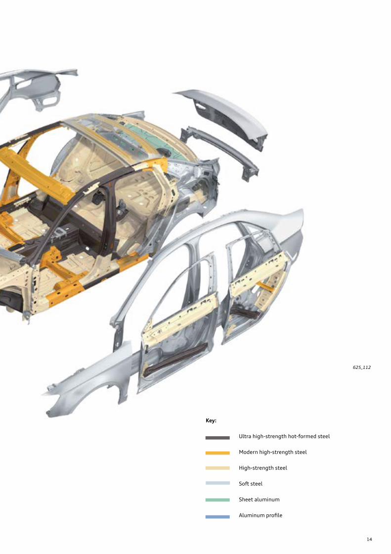
Body panels
Some inner and outer body panels such as the fenders, doors, rear bumper, cross member, and the rear trunk lid are all made from light steel.
The following components are made from aluminum:
• the front bumper cross member• the hood• the rear hat shelf
The use of both light steel and aluminum further helps reduce the weight of the body.
Joining techniques
Both old and new body component joining techniques are in use. In addition to the 4803 classic resistance spot welds used during assembly of the body, the following joining methods are also used:
• MAG welding • Laser welding• Clinching (attachments only)• Solid punch riveting
In each A3 sedan there are over 196 ft (60 m) of glued joints.
The joint between the body side wall and roof is laser welded and then smoothed by brushes to produce a nearly invisible zero joint.
The water drainage paths in the area of the rear trunk lid are joined by Plasmatron welding.
To save more weight, doors and window frames are pressed in one piece. The inner and outer doors are welded by the ultra-modern remote laser technique.
14
625_112
Key:
Soft steel
Sheet aluminum
Aluminum profile
Ultra high-strength hot-formed steel
Modern high-strength steel
High-strength steel

15
10
1 2
3
4
5
6 7
8
9
11
1 Long members (2 left / 2 right)
2 Upper foot room crossmember
3 Lower foot room crossmember
4 Left and right inner A pillars
5 Left and right inner rocker panels
6 Center tunnel
625_114
Forming the backbone of the occupant cell is what are known as form-hardened steels. An extreme temperature change during forming process gives these steels extremely high strength; the parts can be designed with relatively thin walls, making them lightweight.
7 Rear seat crossmember
8 Rear transverse crossmember
9 Left and right upper A pillars
10 Left and right rear long members
11 Left and right inner B pillars
Ultra high strength hot-formed steel components are installed in the following areas
Form-hardened steels represent a 24 percent share of body materials. They are used in the transition from the front of the vehicle to the occupant cell, in the A-pillars, B-pillars, roof arch, center tunnel, side sills and floor panels. Alto-gether, they lower the car’s weight yet provide excellent strength.

16
Panorama tilt sunroof
609_069b
Thermal insulation
The glass roof panel is tinted and provides additional thermal insulation. Thermal insulation is provided by the following reflective components:
• 99 % UV radiation reflection• 92 % heat radiation reflection • 90 % light radiation reflection
The roof opening is larger than that of an internally guided sunroof and creates a particularly airy and spacious interior feel for the occupants.
The 2015 A3 sedan features an optional panorama slide/tilt sunroof.
609_083
The panorama slide/tilt sunroof module meets the statu-tory requirements for anti-pinch protection.

17
609_070
609_071
Roof installation
The panorama slide/tilt sunroof is glued into the roof opening and thus is a major factor contributing to body rigidity.
Glass panel
Wind deflector
Front trim(plastic)
Sliding sunroof frame(plastic)
Roll-up sun-blind
Lifting arm guide frame
Slide/tilt mechanism
Cover forsliding sunroof motor/roll-up sun-blind
Sliding sunroof motor
Component overview
609_122b
Transverse bonded seam
Bonded ring seam

18
Front bumper
Characteristic elements of the vehicle's front end are the one-piece bumper cover and single-frame radiator grille. Large air intakes are located at the lower front.
609_072
Bumper system
Shock absorber
ACC radar sensor
Radiator grille
Impact absorber
Bumper cover locking element
Front bumper cover
Underbody
The Audi A3 has a highly effective acoustic and aerody-namic underbody designed to withstand mechanical and thermal stresses. In addition to aerodynamics, attention was paid to sound absorption, body protection and thermal engine management during the development phase.
609_082
The result is improved airflow around the engine and trans-mission capsule, the cross-members and the wheel arches, thus allowing a low drag coefficient (cw) of 0.31 to be achieved.

19
Components
The passive occupant protection system has the following components:
• Airbag control module• Driver and passenger airbags• Front side airbags• SIDEGUARD® head airbags• Driver and passenger side knee airbag• Front airbag crash sensor• Crash sensors for side impact detection in the doors• Crash sensors for side impact detection in the C pillars• Front inertia reel seat belts with electric and pyrotechnic
belt tensioners• Safety belt warning for all seats• Safety belt switches on all seats in the seat belt buckles• Safety occupancy sensor in front passenger seat
Optional equipment
• Rear passenger side impact airbags
Key to illustration on page 20:
E24 Driver Seat Belt SwitchE25 Front Passenger Seat Belt SwitchE258 Driver Side Rear Seat Belt Switch E259 Passenger Side Rear Seat Belt SwitchE609 Center Rear Seat Belt Switch
G452 Front Passenger Seat Occupant SensorG179 Driver Side Airbag Crash SensorG180 Front Passenger Side Airbag Crash SensorG256 Driver Side Rear Side Airbag Crash SensorG257 Passenger Side Rear Side Airbag Crash SensorG283 Driver Front Airbag Crash SensorG284 Passenger Side Front Airbag Crash SensorG551 Driver Belt Force LimiterG552 Front Passenger Belt Force LimiterG553 Driver Seat Position SensorG554 Passenger Seat Position Sensor
J234 Airbag Control ModuleJ285 Instrument Cluster Control ModuleJ533 Data Bus On-Board Diagnostic InterfaceJ854 Left Front Seat Belt Tensioner Control ModuleJ855 Right Front Seat Belt Tensioner Control Module
K19 Seat Belt Indicator LampK75 Seat Belt Indicator LampK145 Front Passenger Airbag Disabled Indicator Lamp
N95 Driver Airbag IgniterN131 Front Passenger Airbag Igniter 1N132 Front Passenger Airbag Igniter 2N153 Driver Seat Belt Tensioner Igniter 1N154 Front Passenger Seat Belt Tensioner Igniter 1N199 Driver Thorax Airbag IgniterN200 Front Passenger Thorax Airbag IgniterN201 Driver Side Rear Thorax Airbag IgniterN202 Passenger Side Rear Thorax Airbag Igniter N251 Driver Head Curtain Airbag IgniterN252 Front Passenger Head Curtain Airbag IgniterN295 Driver Knee Airbag IgniterN296 Front Passenger Knee Airbag Igniter N297 Driver’s Seatbelt Tensioner Igniter 2N298 Front Passenger Seatbelt Tensioner Igniter 2
T16 Data Link Connector
625_050
Passive safety

20
625_051bx
System overview
Legend:
Powertrain CAN bus
Convenience CAN bus
Input signal
Output signal
Diagnosis CAN bus
G452

21
Vehicle Airbags
625_050Passenger front airbag
The 2015 A3 sedan for the North American market will come equipped with a two-stage adaptive hybrid gas generator front passenger airbag.
Based on accident parameters, Airbag Control Module J234 determines the time interval at which Front Passenger Airbag Igniter 2 N132 is activated after Front Passenger Airbag Igniter 1 N131.
625_125
Front Passenger Airbag Igniter 2 N132
Gas generator Housing
Front Passenger Airbag Igniter 1 N131

22
New generation of connectors A new locking style connector is used on front passenger airbag that incorporates a ground wire connected to the vehicle body.
625_124
The ground circuit provides protection from electro-static discharge. The connector has been mechanically encoded so it can only be installed in one way.
Contact
Locking elementCover
Mechanically encoded housing
Driver and passenger knee airbags
625_122
The Audi A3 sedan is equipped with both driver and passenger knee air bags. Both airbags use tubular hybrid gas generators.
Driver Knee Airbag
Front Passenger Knee Airbag Igniter N296
Knee airbag
Passenger Knee Airbag

23
Driver Front Airbag Crash Sensor G283 Passenger Side Front Airbag Crash Sensor G284
The A3 sedan for the North American region uses two up-front sensors for detection of front and/or rear collisions. They work in conjunction with Airbag Control Module J234.
625_052
These sensors are accelerometers that measure the acceler-ation, deceleration and longitudinal direction of the vehicle.
G284
G283

24
Front Passenger Seat Occupant Sensor G452 Passenger Occupant Detection System Control Module J706
The task of the seat occupancy detection system is to determine the following:
1. If the seat is occupied by a child or if a rearward facing child seat is installed.
2. If an adult is seated.
Passenger Occupant Detection Control Module J706 evalu-ates the signals from Front Passenger Seat Occupant Sensor G452. If J706 recognizes an empty passenger seat or that a rearward facing child seat is installed, it instructs Airbag Control Module J234 to disable the passenger front airbag and knee airbag.
This means that in the event of a collision, neither the passenger front airbag nor front passenger knee airbag would deploy.
Front passenger Airbag -disabled- Indicator Lamp K145 in the instrument panel warns the driver of the status of the passenger airbag and knee airbag. If Airbag Control Module J234 has disabled these airbags based on the signals from J706, warning lamp K145 will remain illuminated.
In addition to the warning lamp, Airbag Control Module J234 will also issue an optical and acoustic warning if the seat is unoccupied or if a safety belt has been unbuckled. Detection of an unbuckled belt is determined by a signal from Front Passenger Seat Belt Switch E25.
Front Passenger Seat Occupant Sensor G452
G452 is a capacitor-type sensor. A capacitor is made of two plates (electrodes) and an insulator (dielectric), sand-wiched between them.
When voltage is applied to one of the electrodes and the other electrode is connected to the battery‘s negative terminal, the capacitor begins to accumulate energy. The capacitance of a capacitor can be altered by varying the size of the electrode plate or the dielectric.
625_058
Dielectric material
Electrode Electrode
Function
With this type of occupant detection system, the vehicle body and sensor G452 represent the two plates of the capacitor. These components obviously do not change in size.
The dielectric consists of the upholstery, the atmosphere, the adjoining seat trim parts and the occupant. The capaci-tance will change due to the liquid content of the occu-pant‘s body compared to when the seat is unoccupied or if a rear facing child seat is installed. This capacitance signal data is interpreted by Passenger Occupant Detection System Control Module J706 to determine if the seat is occupied or not.
625_059
Front Passenger Seat Occupant Sensor G452
Passenger Occupant Detection System Control Module J706

25
Installation location
G452 is installed under the seat cover but on top of the seat heater elements.
Passenger Occupant Detection System Control Module J706
In principle, J706 measures the capacitance of Front Pas-senger Seat Occupant Sensor G452.
The values from J128 are read cyclically by J706 and trans-ferred to Airbag Control Module J234 via a LIN bus.
Diagnosis
J706 is connected to G452 via a coaxial cable and is sup-plied assembled to the factory as a unit. The coaxial cable and the plug of the coaxial cable must not be repaired. There are different seat variations and thus different con-trols module variations for J706. The software in the ECU is matched to the respective seat.
Control module J706 and sensor G452 cannot be replaced separately. They are matched during production. If they are replaced, a Basic setting must be performed with the Scan Tool. During this basic setting the serial number of the installed components are entered into the Airbag Control Module.
625_060
625_061
Front Passenger Seat Occupant Sensor G452
Seat foam
Front Passenger Seat Occupant Sensor G452
Coaxial cable
Passenger Occupant Detection System Control Module J706
Serviceable components
ReferencePlease refer to the latest repair and parts information when replacing the seat sensor and control module.

26
In combination with Audi pre sense basic, the 2015 Audi A3 is equipped with reversible safety belt tensioners driven by electric motors. This is in addition to the pyrotechnic belt tensioners.
Airbag Control Module J234 operates Left and Right Seat Belt Tensioner Control Modules J854 and J855 as LIN modules.
When Audi pre sense basic detects specific driving situa-tions, signals are sent to the data bus. The airbag control module evaluates the signals and, if necessary, instructs the seat belt tensioner control module to partially or fully tension the safety belts via an electric motor. For further information on Audi pre sense, refer to the chapter on Active safety, page 31.
The automatic safety belt retractors use rack-type pyro-technic belt tensioners. If an automatic seat belt retractor with seat belt tensioner control module is replaced, the basic setting procedure must be performed using the “Guided Fault Finding“ function.
Front safety belt tensioner
Side airbag crash sensors
The side airbag crash sensors for the driver and passenger sides (G179 and G180) are capacitive pressure sensors.
The pressure sensors have a new mounting concept and are no longer bolted to the inner door panel The pressure sensors are inserted into the inner door panels and then secured into place by twisting.
625_086
625_146
Safety belt tensioner control module
Reversible tensioner with electric motor
Pyrotechnic safety belt tensioner
Retaining lugs
Gasket Turning aidConnector housing
Active belt force limiter
27
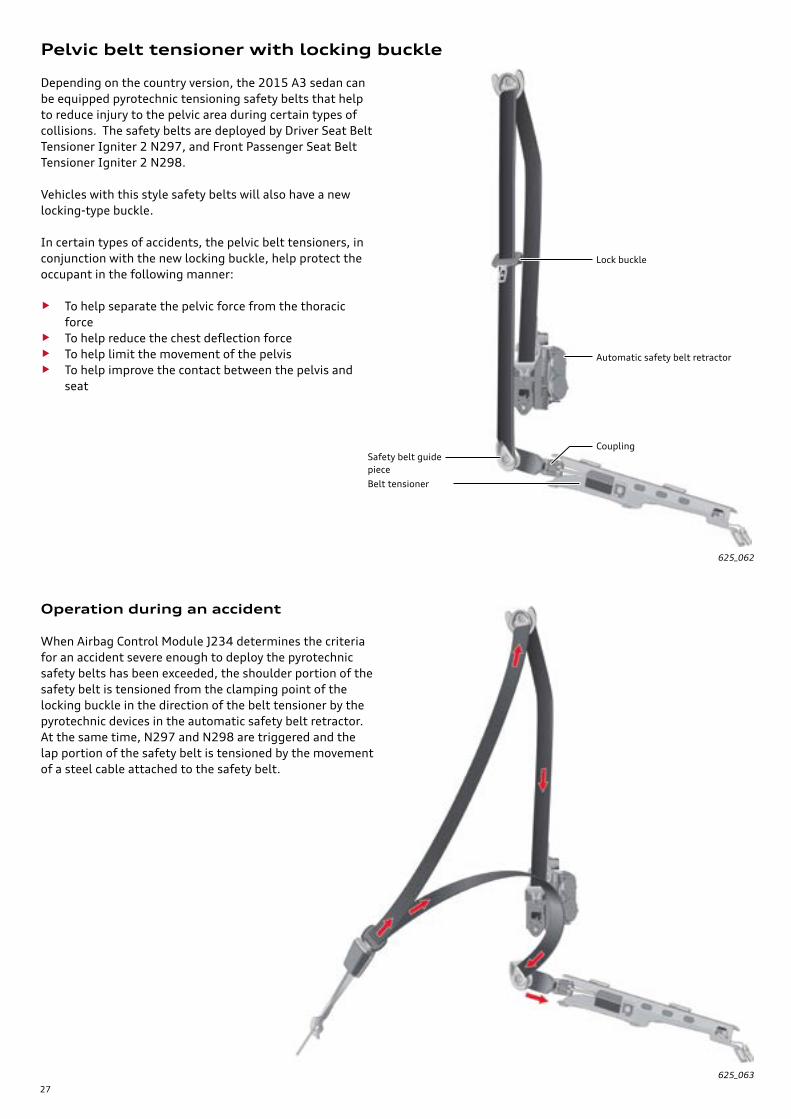
Pelvic belt tensioner with locking buckle
Depending on the country version, the 2015 A3 sedan can be equipped pyrotechnic tensioning safety belts that help to reduce injury to the pelvic area during certain types of collisions. The safety belts are deployed by Driver Seat Belt Tensioner Igniter 2 N297, and Front Passenger Seat Belt Tensioner Igniter 2 N298.
Vehicles with this style safety belts will also have a new locking-type buckle.
In certain types of accidents, the pelvic belt tensioners, in conjunction with the new locking buckle, help protect the occupant in the following manner:
• To help separate the pelvic force from the thoracic force
• To help reduce the chest deflection force• To help limit the movement of the pelvis• To help improve the contact between the pelvis and
seat
Operation during an accident
When Airbag Control Module J234 determines the criteria for an accident severe enough to deploy the pyrotechnic safety belts has been exceeded, the shoulder portion of the safety belt is tensioned from the clamping point of the locking buckle in the direction of the belt tensioner by the pyrotechnic devices in the automatic safety belt retractor. At the same time, N297 and N298 are triggered and the lap portion of the safety belt is tensioned by the movement of a steel cable attached to the safety belt.
625_062
625_063
Lock buckle
Automatic safety belt retractor
Safety belt guide piece
Belt tensioner
Coupling

28
Function - Ignition and Pelvic belt tensioning
When a signal from Airbag Control Module J234 ignites the pyrotechnic pelvic belt tensioner propellant there is a sudden increase in the pressure chamber.
Function - Locking
Because the steel cable is connected to the lap portion of the safety belt, the belt is tightened by approximately 4.0 in (100 mm) when the igniter is triggered. The locking buckle acts as a load fixing point and anchors the lap portion of the safety belt at the buckle.
Pelvic belt tensioner
Construction
The pelvic belt tensioner consists of the following parts:
625_069
625_070
625_071
The sudden increase in pressure propels the piston, balls and locking cone and steel cable forward.
When the cable has reached its limit, there is a small reac-tive backward movement. This forces the balls to move against the cone shape of the piston and deform the inner tube of the pressure chamber. This prevents cable from returning and holds the safety belt firmly against the occupant’s lap.
Pressure chamber tubeSteel Cable
Coupling (connects pelvic tensioner to lap portion of the safety belt)
Locking cone (Fixed to the seat cable)
Piston with ball retainer
wire with connector
BallsThey are in constant contact with the pressure chamber tube.
Rope seal(Seals the steel cable from the pressure chamber)
Pressure chamber seal
Polytechnic propellant charge
max. 100 mm
deformation of the pipe

29
Locking buckle
A newly designed safety belt buckle is used. The lock buckle prevents movement and forms a separate load path for the shoulder and lap portion of safety belt in the event of an accident.
625_064
Guide piece
Foam piece
Steel cable, lap belt tensioner
625_065
Point where safety belt is stitched to pelvic belt tensioner
Coupling point
The end of the lap portion of the safety belt is routed through a guide piece and stitched to a joining piece of the pelvic belt tensioner assembly. A foam piece covers the joined pieces to prevent noise.
Joining point of safety belt and pelvic belt tensioner.
Installation location
The pelvic belt tensioner is located by tabs and then bolted into place along the lower inner front door sill.
625_072
tab connection in sill
NoteThe Pelvic belt tensioner is a pyrotechnic device. Always follow all safety Warnings and Cautions as outlined in the repair literature when working on or near these components.

30
Design and operation
The locking buckle has a movable spring loaded piece that allows the safety belt to move freely under normal operat-ing conditions.
Function
625_066
During an accident in which the Pelvic belt tensioner has be triggered, the locking piece is displaced and blocks the safety belt from moving.
Cover
Lock buckle
Seat Belt
locking piece with spring
BlockedNot blocked
625_067 625_068
ReferenceFor information on removing and installing the lap belt tensioner please refer to the current repair literature and Guided Fault Finding using the VAS Scan Tool.
Locking piece
Seat belt
Lock buckle

31
609_075
609_076a
Audi pre sense
Audi pre sense is able to detect critical driving situations, and initiate measures to prepare the vehicle and occupants for an impending collision.
This is made possible by networking various in-vehicle systems. The systems send data continuously to the data bus. Other control modules are able to evaluate this infor-mation and take appropriate action.
Audi pre sense basic
Longitudinal dynamics function
When vehicle is moving forward at a speed greater than 18.6 mph (30 km/h) and the driver executes a “hazard braking maneuver” in which the brake pressure reaches a defined level, the reversible safety belt tensioners are partially tensioned.
Please note that Audi pre sense cannot prevent collisions. It serves only to assist the driver and potentially reduce the severity of the collision.
ASR/ESP ButtonE256
J234 then instructs Seat Belt Tensioner Control Modules J854 and J855 to fully tension the safety belts. Depending on the situation, J104 can also activate the hazard warning flashers.
Drive profile selection switch moduleE592
If the ESP is set to “Sport” or “OFF” using either ASR/ESP Button E256, Driving Profile Selection Switch Module E592 or if the Audi drive select is set to “dynamic” via the MMI, the safety belts will not be partially tensioned.
Emergency braking function
During an “emergency braking” maneuver in which the brake pressure exceeds a defined value for a defined period of time, the reversible safety belt tensioners are fully tensioned by the electric motors.
In this scenario, Airbag Control Module J234 evaluates the signals sent on the data bus from ABS/ESP Control Module J104.
Active Safety
32
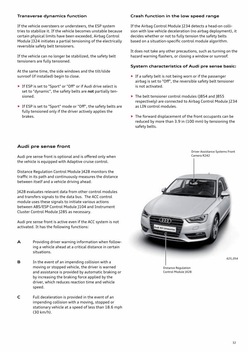
625_054
Distance Regulation Control Module J428
Driver Assistance Systems Front Camera R242
Transverse dynamics function
If the vehicle oversteers or understeers, the ESP system tries to stabilize it. If the vehicle becomes unstable because certain physical limits have been exceeded, Airbag Control Module J324 initiates a partial tensioning of the electrically reversible safety belt tensioners.
If the vehicle can no longer be stabilized, the safety belt tensioners are fully tensioned.
At the same time, the side windows and the tilt/slide sunroof (if installed) begin to close.
• If ESP is set to "Sport" or "Off" or if Audi drive select is set to "dynamic", the safety belts are not partially ten-sioned.
• If ESP is set to "Sport" mode or "Off", the safety belts are fully tensioned only if the driver actively applies the brakes.
Crash function in the low speed range
If the Airbag Control Module J234 detects a head-on colli-sion with low vehicle deceleration (no airbag deployment), it decides whether or not to fully tension the safety belts based on a situation-specific control module algorithm.
It does not take any other precautions, such as turning on the hazard warning flashers, or closing a window or sunroof.
System characteristics of Audi pre sense basic:
• If a safety belt is not being worn or if the passenger airbag is set to "Off", the reversible safety belt tensioner is not activated.
• The belt tensioner control modules (J854 and J855 respectively) are connected to Airbag Control Module J234 as LIN control modules.
• The forward displacement of the front occupants can be reduced by more than 3.9 in (100 mm) by tensioning the safety belts.
Audi pre sense front
Audi pre sense front is optional and is offered only when the vehicle is equipped with Adaptive cruise control.
Distance Regulation Control Module J428 monitors the traffic in its path and continuously measures the distance between itself and a vehicle driving ahead.
J428 evaluates relevant data from other control modules and transfers signals to the data bus. The ACC control module uses these signals to initiate various actions between ABS/ESP Control Module J104 and Instrument Cluster Control Module J285 as necessary.
Full deceleration is provided in the event of an impending collision with a moving, stopped or stationary vehicle at a speed of less than 18.6 mph (30 km/h).
Audi pre sense front is active even if the ACC system is not activated. It has the following functions:
Providing driver warning information when follow-ing a vehicle ahead at a critical distance in certain situations.
A
B In the event of an impending collision with a moving or stopped vehicle, the driver is warned and assistance is provided by automatic braking or by increasing the braking force applied by the driver, which reduces reaction time and vehicle speed.
C

33
609_061
Approachingvehicle driving ahead
Speedsynchronization
Following at a critical distance including visual distance warning (ACC warning lamp)
Collision
Function A
The driver is warned visually by a message in the Driver Information System when approaching another vehicle ahead or when following this vehicle at a critical distance at a synchronized speed.
The critical distance is defined as the distance at which a collision is likely to occur in the event of sudden heavy braking of a vehicle driving ahead, even if the driver of the following vehicle reacts quickly.
609_063
Function B
When the vehicle approaches a moving vehicle, Instrument Cluster Control Module J285 warns the driver visually and audibly if certain defined limits are exceeded. These warn-ings are issued within a certain period of time prior to the last braking opportunity for collision avoidance before the actual collision.
The timing of warnings depends on the driver's degree of activity. Depending on steering, pedal and turn signal inputs, the system classifies the driver as active or inactive and, consequently, as attentive or inattentive. If the driver is attentive, the warning will be issued later than for an inattentive driver.
At the same time, ABS/ESP Control Module J104 prefills the brake system and modifies the deployment algorithms for Hydraulic Brake Assist. This means that Hydraulic Brake Assist begins to build up brake pressure even at low brake pedal actuation speeds.
If the driver does not respond to the warnings or, for example, eases off the accelerator, J104 performs a warning braking application.
The warning braking application is a very brief but easily noticeable braking operation and does not serve to slow the
Prefillbrake systemHydraulic Brake Assist reacts with higher sensitivity
Driver warning visual, audible(forward collision warning)
Warning braking
Partial braking operation I orpartial braking operation II (on models with front camera for driver assistance systems)
Collision
Target braking
vehicle down. It alerts drivers to the traffic situation and indicates to drivers that they must react immediately in order to avoid an impending collision. Depending on how attentive the system evaluates the driver to be, the warning braking application occurs within a specific period of time ahead of the last opportunity for braking and evasive action in order to avoid a collision.
If the driver still fails to react or ease off the accelerator, the vehicle is braked by partial braking operation I, which applies up to 35% of maximum braking force.
If Driver Assistance Systems Front Camera R242 also detects the obstacle, the braking force is increased to up to 60% of the maximum by partial braking operation II.
If the driver applies the brakes, a target braking action can be performed in all phases described above (prefill brake system, reconfiguration of Hydraulic Brake Assist, driver warning, warning braking application, partial braking operations I and II). During the target braking action, the Audi pre sense front system calculates whether the driver is applying sufficient braking force to be able to avoid a collision. If this is not the case, the required brake pressure is increased depending on the situation.

34
Function C
Audi pre sense front also includes a function for “full decel-eration at speeds from 18.6 mph (30 km/h).”
If Distance Regulation Control Module J428 detects an impending collision when the vehicle is travelling at a speed of less than 18.6 mph (30 km/h), ABS/ESP Control Module J104 pre-fills the brake system.
The deployment algorithms for Hydraulic Brake Assist are adjusted at the same time. Hydraulic Brake Assist thus begins to build up brake pressure even at low brake pedal actuation speeds. If the driver fails to brake or does not apply sufficient braking force in a critical situation, J104 executes a braking action and applies near-maximum braking if necessary.
Before the braking action occurs, the driver is alerted both audibly and visually through the DIS that the vehicle is about to brake independently or provide additional braking force.
If the vehicle has independently braked to a standstill without driver intervention, three more audible signals are given.
The three additional signals given alerts the drivers that they must actively take control over the vehicle by applying the brake. If the driver fails to take control (especially in a vehicle equipped with an automatic transmission) the vehicle will begin to roll.
Driver prioritization over system
If the driver clearly takes evasive action, accelerates or brakes during the individual phases of Audi pre sense front (functions A to C), the action momentarily being taken by Audi pre sense front (for example, partial braking operation I) will be suppressed or cancelled.
If the obstacle is no longer relevant after evasive action has been taken, Audi pre sense front will cease to provide assistance in this case.
System characteristics with respect to "full deceleration at speed of less than 18.4 mph (30 km/h)"
• The driver is not given advance warning.
• The system reacts to crossing or oncoming vehicles and objects with low radar scatter (for example, pedestrians).
• The system reacts to vehicles which are travelling in the same direction, have stopped or are stationary.
609_064
Prefill brake systemHydraulic Brake Assists reacts with higher sensitivity
CollisionFull deceleration with visual and audible driving warning prior to intervention

35
Settings and displays There are two options for deactivating Audi pre sense front in the MMI.
• Option 1: Prewarning off – the audible and visual warn-ings (distance and forward collision warnings) are deactivated.
• Option 2: System off – the audible and visual warnings (distance and forward collision warnings), warning braking, partial and target braking and the "full deceler-ation at speeds of below 18.4 mph (30 km/h)" functions are deactivated. The functions remain deactivated until they are reactivated in the MMI.
If the ESP is set to “Sport” or “OFF” using the ASR/ESP Button E256, then the audible and visual warnings, the warning braking, the partial and target braking, and the "full deceleration at speeds of below 30 kph" functions of Audi pre sense will also be deactivated.
609_078a
609_079a
ReferenceFor more information about Driver Assistance Systems Front Camera R242, refer to eSelf-Study Program 970343, The 2015 Audi A3 Vehicle Electronics and Driver Assistance Systems.
ReferenceFor additional information about ACC, refer to eSelf-Study Program 960143, The 2015 Audi A3 Running Gear and Suspension System.
Audi pre sense remains deactivated until:
• ESP is reactivated with E256.
• the ignition is switched off and on again, thereby reacti-vating ESP.
• ACC is activated, since this would result in automatic activation of ESP.
If ESP (Electronic Stabilization Program) is set to "Sport" or "Off" button E256, the following text is temporarily dis-played in the DIS: "Audi pre sense: off".
If only the pre-warning has been deactivated, no text message is displayed in the DIS.
If the system has been deactivated, the driver is warned by a text message in the DIS - Audi pre sense off - whenever the ignition is switched on. This alerts the driver to the fact that the system is switched off.
Both versions of Audi pre sense are activated.

36
Data bus overview
ABS/ESP Control Module J104
Prefill brake system ← I Warning braking ← I Partial braking operations I and II ← I Target braking ← I
Driving speed → O Wheel speed FR → O Wheel speed FL → O Wheel speed RR → O Wheel speed RL → O Brake pressure → O TCS / ESP status → O
Activate hazard warning flashers → O Longitudinal acceleration → O Transverse acceleration → O Rotation about vertical axis → O
Vehicle Electrical System Control Module J519
Reversing light switch status → O Close sliding sunroof ← I Close sliding sunroof → O (to LIN user sliding sunroof control unit J245)
Instrument Cluster Control Module J285
Audible and visual warnings ← I Display "Audi pre sense" system malfunction ← I
Information Electronics Control Module 1 J794
Audi drive select set-up → O
Airbag Control Module J234
Seat belt buckle status → O Passenger airbag status → O Close side windows → O Close tilt/slide sunroof → O Electrical partial tensioning → O (to LIN users front left and right seat belt tensioner control units, J854 and J855 respectively)Electrical full tensioning → O (to LIN users front right and left seat belt tensioner control units, J855 and J854 respectively)Seat belt tensioning status → O
Wheel speed FR ← I Wheel speed FL ← I Wheel speed RR ← I Wheel speed RL ← I Longitudinal acceleration ← I Transverse acceleration ← I Rotation about vertical axis ← I Vehicle speed ← I Brake pressure ← I TCS / ESP status ← I Accelerator position ← I Audi drive select set-up ← I Reversing light switch setting ← I Steering angle ← I
Distance Regulation Control Module J428
Prefill brake system → O Warning braking → O Partial braking operations I and II → O Target braking → O Audible and visual warnings → O Display "Audi pre sense" system malfunction → O
Steering angle ← I TCS / ESP status ← I Accelerator position ← I Brake pressure ← I Wheel speed FR ← I Wheel speed FL ← I Wheel speed RR ← I Wheel speed RL ← I
Power Steering Control Module J527
Steering angle → O
Front right belt tensioner control units J855 (LIN user of airbag control unit J234)
Electrical partial tensioning ← I Electrical full tensioning ← I
Front left belt tensioner control units J854 (LIN user of airbag control unit J234)
Electrical partial tensioning ← I Electrical full tensioning ← I
Power Sunroof Control Module J245
Close sliding sunroof ← I (LIN user of onboard power supply control unit J519)
Steering Column Electronics Control Module J527
Cruise control system status → O
Engine Control Module J623
Accelerator position → O
Door Control Modules J386, J387, J926, J927
Close side windows ← I
609_062
The overview shows some of the information exchanged via data bus.
Data bus in generalLIN bus
Key: ← I Data is received (input)→ O Data is sent (output)

37
Cylinder head with Integrated Exhaust Manifold (IEM)
Optimized thermal management
1.8L and 2.0L TFSI engines
Technical feature overview
2.0L TFSI engine shown. The 1.8L TFSI engine does not have continuously adjustable exhaust camshaft timing.
Engine Temperature Control Actuator N493
Engines

38
ReferenceFor detailed information about the 1.8L and 2.0L TFSI engines, please see eSelf-Study Program 920243, Third generation Audi 1.8L and 2.0L engines from the EA888 model family.
609_156
Friction optimization and lightweight design
Combined FSI/MPI injection
Both the 1.8L TFSI and 2.0L TFSI engines for the North American market will only have the FSI injection system. The dual injection may be introduced at a later date.
625_107

39
2.0l Second generation TDI engine
Technical features
Cylinder block with integrated balancer shafts
Cylinder head with variable valve timing
Oxidizing catalytic converter and diesel particulate filter
609_041
609_043
609_042
Diesel engines

40
609_017
609_044
609_045
609_046
Oil pump with integral vacuum pump
Active coolant pump
Intake manifold module with integrated charge air cooler

41
Engine/transmission combinations
1.8l TFSI engine
2.0l TFSI engine
0CW
0D9
0CW
Transmission designations:
0AH (MQ200_5F)
0AJ (MQ200_6F)
02S (MQ250_6F)
02Q (MQ350_6F)
0FB (MQ350_6A)
0CW (DQ200_7F)
0D9 (DQ250_6A)
2.0l TDI engine
Explanation of manufacturer designation:Example: MQ350-6F
M Manual transmission
D Dual clutch transmission
Q Transverse installation
350 Nominal torque capacity
6 Number of gears
F Front wheel drive
A All-wheel drive (quattro)

42
Notes

43
Overview
The drive train components of the 2015 A3 are based on proven technology and include the new 5th generation Haldex coupling on quattro models.
The installation position of the transmission has been adapted to the modular transverse module (MQB) by modi-fying the transmission flanges and mounting points. The original 6-speed dual clutch transmission 02E is now desig-nated as the 0D9. It’s installation is inclined 12 degrees further back than the 02E.
Final drive Rear axle drive vent
Haldex coupling vent
Haldex coupling
Haldex Clutch Pump V181
All Wheel Drive Control Module J492
609_129
Rear axle drive 0CQ
Power transmission

44
Both 02S and 0D9 dual clutch transmissions are integrated with the Innovative Thermal Management system for the 2015 A3 model line-up. The 02S is used in the 1.8L A3 Front Track model while the 0D9 is used in the 2.0L quattro model.
The transmission cooling circuit is initially open during the start phase of a cold engine. During this time, Transmis-sion Coolant Valve N488 is energized when the ECM switches the valve to ground. If there is enough heat available for the engine and for heating the passenger compartment, the valve is de-energized. The cooling circuit is now closed and the ATF is heated to operating tempera-ture by the engine coolant. The ATF temperature value is transferred from the transmission to the ECM via the Powertrain CAN bus. If the ATF has reached operating temperature, valve N488 is re-energized and the cooling circuit is open.
If the ATF temperature exceeds a permissible value, N488 is de-energized again. The cooling circuit is closed. Because the engine coolant temperature is kept below the maximum permissible ATF temperature in this case, the ATF is cooled by the engine coolant.
ITM for the 02S and 0D9 transmissions
Selector mechanism with emergency release.For further information, refer to page 52.
Selector lever cable for actuating the parking lock
Transmission Coolant Valve N488 − Activated and diagnosed by the ECM − Energized: valve closed, open coolant circuit − De-energized: valve open, closed cooling circuit
12V
Coolant feed
Coolant return
0D9 transmission
12°
609_130
609_131

45
Component overview
The most notable feature of the 5th generation Haldex coupling is a new pressure control system. The hydraulic pressure required for the Haldex coupling is produced by a pump with centrifugal governor. The new Haldex coupling is 3.7 lb (1.7 kg) lighter than the 4th generation coupling.
An electric motor drives a six axial piston pump. The pistons are pushed against an inclined thrust plate. When the pump cylinder rotates, the pistons execute an axial stroke and move the Haldex oil to the pressure side of the pump.
Axial piston pump with integrated centrifugal governor
5th generation Haldex coupling
Axial needle bearing
Thrust plate
Clutch cage
Clutch plate assembly
Thrust plate
Axial needle bearing
Working piston with seals
Haldex coupling pump V181Pressure sideCentrifugal lever
Axial piston
Thrust plate
Haldex Clutch Pump V181
Centrifugal force control valve
Pump cylinder
Pump sump
Suction side
609_132

46
All Wheel Drive Control Module J492
Pressure relief valve
All Wheel Drive Control Module J492 exchanges data over the Suspension CAN bus. Its software determines the pump output based upon programmed characteristic curves, which in turn generates the required hydraulic pressure delivered to the working piston cylinder.
The electric motor of the pump is controlled with a pulse width modulated 12 volts. Current input is also measured.
The hydraulic pressure is determined as a function of current input based on the characteristic curves. If a higher pressure is required, pump output is increased by pulse width modulation of the voltage. To reduce the pressure in the working piston cylinder, pump output is decreased. The system is supplied power via Terminal 30 and is protected by a 15A fuse.
The Haldex unit hydraulic system is protected by a pressure relief valve. It consists of a valve ball and steel spring. If a hydraulic pressure greater than 638.1 psi (44 bar) devel-ops, the spring force is no longer sufficient to hold the valve ball in place. Its movement unblocks the relief port and the Haldex oil is displaced to the suction side of the axial piston pump.
Needle bearing
Drive hub
2-way connector
All Wheel Drive Control Module J492
8-way connector
Oil sleeve
Housing
Pressure relief valve
Flanged nut
Flange
Ring seal
Ball bearing
Snap ring
609_133
609_134
O-ring

47
Oil supply / hydraulic diagram
The axial piston pump with an integrated centrifugal gover-nor is driven by Haldex Clutch Pump V181. The centrifugal force acting on the centrifugal levers of the controller increases with axial piston pump speed. The valve balls of the centrifugal force control valves are pushed down into the valve seat more firmly. This increases the pressure maintained by the valves. This design allows the system to achieve outstanding pressure increase and pressure reduc-tion times.
The hydraulic pressure supplied to the working piston is controlled by varying the speed of Haldex Clutch Pump V181. When the speed of V181 increases, the pressure to the working piston increases. This in turn increases pres-sure to the clutch plate assembly allowing more torque to be transmitted.
If the speed of V181 decreases, there is less pressure supplied to the working piston and less torque can be transmitted.
609_135
Working piston Pressure relief valve
Centrifugal force control valve
Clutch cage
Haldex Clutch Pump V181
Centrifugal lever
Thrust plate
Pump sump
Axial piston pump with integral centrifugal governor
Pressurized oil supply to the working piston

48
609_019
609_021
At low speeds, there is no pressure build-up inside the working piston cylinder. Due to the low speed of the pump motor, the centrifugal levers do not apply pressure to the valve balls.
As the pump motor speed increases, pressure builds up inside the cylinder of the working piston. The centrifugal levers now apply pressure to the valve balls and close the gap. The rising pressure pushes the valve balls back slightly, bringing the centrifugal force and the hydraulic force into equilibrium.
Working piston
Clutch plate assembly
Haldex oil sump
Operation - low pump motor speed
The pumped oil flows back into the sump through the centrifugal force control valves of the centrifugal governor.
Pressure build-up due to increased pump motor speed
The pressure inside the working piston, and therefore, the amount of torque which can be transmitted, rises with increasing motor speed.
The valve ball is pushed more firmly into the valve seat by the increased speed of the centrifugal governor.
Centrifugal governor with increased speed
Centrifugal governor and direction of rotation
Centrifugal force
Centrifugal lever
Pressure relief valve
Centrifugal force control valve
Haldex Clutch Pump V181
Centrifugal lever mount
pressure < 638.1 psi (44 bar)
pressure < 638.1 psi (44 bar)
Color key:
Vacuum Un-pressurized Oil overflow
Color key:
Vacuum Un-pressurized Pressure inside working piston cylinder

49
609_020
609_050
At high pump motor speeds, centrifugal levers apply pres-sure to the valve balls to such an extent that the pressure inside the working piston cylinder rises to an unacceptable level.
When the pump motor speed slows, the centrifugal levers exert less pressure on the valve balls. The pressure is relieved through the open valve gap until the centrifugal force and the hydraulic force are equal.
Operation - extremely high pump motor speed
Pressure reduction due to decreased pump motor speed
When the pressure exceeds 638.1 psi (44 bar), the pressure relief valve opens and limits the system pressure.
Overspeeding centrif-ugal governor
Centrifugal governor with reduced speed
Pressure is relieved
Pressure relief valve opens
pressure > 638.1 psi (44 bar)
pressure < 638.1 psi (44 bar)
Color key:
Vacuum Un-pressurized Excess pressure inside working piston cylinder
Color key:
Vacuum Un-pressurized Controlled pressure inside working piston cylinder

50
Function diagram
All Wheel Drive Control Module J492 communicates with ABS/ESP Control Module J104 and Power Steering Control Module J500 over the Suspension CAN bus.
Service
All Wheel Drive Control Module J492, Haldex Clutch Pump V181 and flange for the propeller shaft are replaceable.
609_136
Suspension CAN bus, high
Suspension CAN bus, low
Term. 15
Term. 30
Term. 31
J492: All Wheel Drive Control ModuleV181: Haldex Clutch Pump
J492
1
V181
2 87654321
It communicates with DSG Transmission Mechatronic J743, Instrument Cluster Control Module J285, and Engine Control Module J623 via Data Bus On Board Diagnostic Interface J533.
Various seals for the housing are also replaceable. Please refer to the current repair literature for the latest informa-tion.
609_137
All Wheel Drive Control Module J492
NoteHaldex oil and rear axle oil are NOT the same. Do not mix them up during service work or irreparable damage to components will occur.
Flange
Haldex oil drain plug
Haldex Clutch Pump V181
Oil bleed port for double shaft oil seal
Axle oil drain plug
Axle oil filler and inspection plug
Haldex oil filler and inspection plug
Change intervals
The Haldex oil must be changed every 3 years, regardless of mileage. The axle oil is not subject to a change interval.

51
Diagnostics
All Wheel Drive Control Module J492 can be accessed with the VAS Scan Tool via Address Word 22.
The following functions are available:
• Control module identification• Specified/actual comparison
The validity of the software, the coding and the adapta-tion channels for the vehicle is checked.
• Check DTC memoryQuery and erase.
• Output check diagnosisTo activate the output check diagnostics, the engine must be running the coolant temperature less than 140 °F (60 °C).
If the output check diagnostic is operating, the multi-plate clutch is kept closed up to a speed of 4 mph (6 km/h). The vehicle must be driven below this speed with the steering wheel at full lock (left or right). This places a strain on the drive line causing the rear axle to shudder. When the driven speed reaches 4 mph (6 km/h), the clutch opens and the strain on the drive line is relieved. This is an indication that the Haldex coupling is working.
• Basic settingThe basic setting function can be used to assign Haldex Clutch Pump V181 to a matching characteristic curve stored in All Wheel Drive Control Module J492.
• Read MVBs• Replace control module
Includes all the work operations necessary to replace the control module.
Replacing Haldex Clutch Pump V181After replacing Haldex Clutch Pump V181, the first thing to do is to correct the Haldex oil level. Next, an output check diagnosis must be done on the vehicle while it is stationary and then the oil level checked again. Finally, the basic setting procedure must be performed.
Emergency running modeTwo temperature sensors are mounted on the printed circuit board of control module J492 which monitor the electronic components. The temperature of the multi-plate clutches is calculated based on these temperature values. If the calculated temperature exceeds a specific threshold, the Haldex coupling is shut off. No indication or warning is given to the driver.

52
Transmission selector mechanism
Selector Lever Transmission Range Position Display Unit Y26
If the selector lever is in P, switch F319 is open. It is closed in all other positions. The information "selector lever in P", "switch F319 open" cancels the ignition key removal lock and is required to enable engine starting. If there is a short circuit to ground in the circuit, the engine cannot be started and the ignition key cannot be removed in models without Advanced key.
Selector lever positions P, R, N, D/S and the tiptronic signals “tiptronic gate recognition”, “tip plus” and “tip minus” are recognized by Selector Lever Sensor System Control Module J587 and sent to DSG Transmission Mechatronic J743 via the Powertrain CAN bus.
To shift from D to S (or S to D), the lever needs only to be flicked backwards out of D/S once. The lever always springs back to the D/S position.
E313 Selector Lever
F319 Selector Lever Park Position Lock Switch
J587 Selector Lever Sensor System Control Module
N110 Shift Lock Solenoid
Y26 Selector Lever Transmission Range Position Display Unit
Parking lock emergency release mechanism
The parking lock emergency release mechanism can be accessed by unclipping the selector lever gate from the center console and pushing the insulating foam to the side.
609_138609_139
609_140
Emergency release mechanism
Powertrain CAN bus, high
Powertrain CAN bus, low
Term. 15
Term. 30Term. 31
P
A1 A2 A10A9A8A7A6A5A4A3
Term. 58d
F319
J587E313
N110
Y26 P R N D/S
B1 B2 B10B9B8B7B6B5B4B3
31 +/- 58dD/SNRP
Selector lever position
A discrete wire to Steering Column Electronics Control Module J527 in vehicles without Advanced key and to Electronic Steering Column Lock Control Module J764 in vehicle with Advance key.
P

53
Various fuel systems are used in the Audi A3 ’13. Various factors dictate which system is fitted in the vehicle:
• Engine type• quattro or front wheel drive• Climate zone of market
Fuel tank for 2.0 TDI Front track models with SCR tank
Fuel tank for 1.8L TFSI Front track
Fuel tank for 2.0 TFSI quattro models
Fuel tanks

54
609_034
2.0l TDI engine
Oxidizing catalytic converter
Diesel particulate filter
Exhaust Flap Control ModuleJ883
Rear muffler
609_175
Close-coupled main catalytic converter
Center muffler
Rear muffler
Exhaust system
1.8L TFSI and 2.0L TFSI engines

55
ABS/ESP from Continental TPMS standard
Tandem master brake cylinder with single 10” or 11” diaphragm power brake booster. (Engine dependent)
15“ or 16” inch brakes standard. 17“ inch brakes for S3 sedan
Distance Regulation Control Module J428 when optional ACC installed
Electro-mechanical steering is standard equip-ment. Dynamic steering to be offered at a later date.
MacPherson strut front axle in combina-tion with aluminum sub frame and steering knuckle.
Design concept
A design goal for running gear of the A3 sedan was to have a finely balanced axle load distribution of 59% front to 41% rear. The forward placement of the front axle in relation to the body played a significant role in this accomplishment. The use of the same components across the worldwide A3 model line-up was also of major consideration.
The application of the Audi ultra lightweight strategy was also addressed by the use of aluminum axle components and smaller wheel offsets.
Overview
Running gear

56
ReferenceFor more information about the A3 running gear, please refer to eSelf-Study Program 960143, The 2015 Audi A3 Running Gear and Suspension System.
ABS/ESP from Continental TPMS standard
625_145
Four-link rear suspension is standard on all North American region vehicles except those with the 2.0L TDI engine. (Delayed introduc-tion.)
15” brakes standard. 17” brakes standard for S3Electronic Parking Brake is standard equipment.
16” through 19” wheels available depending on model and optionsFour spoke steering wheel is standard. Different four spoke and three spoke steering wheels available depending on model and optional equipment selected

57
Suspension variations
625_147
Dynamic suspension The Dynamic suspension is standard equipment for the 2015 A3 sedan.
Sport suspension The sports suspension is optional. In models with sports suspension, ride height is 0.59 in (15 mm) lower than in models with the standard suspension.
S line suspension The ride height is lowered .98 in (25 mm) compared to the standard suspension. The tuning is more sporty than the Sport suspension. The S line suspension comes with 18 inch wheels as standard.
Suspension system with electronic damping control
This suspension system is available only on S3 models. It is based on the Audi magnetic ride system currently used in other Audi models.
Tire Pressure Monitoring System
The 2015 Audi A3 uses the second generation tire pressure monitoring system. It functions based on information from the ABS/ESP control module. It is identical to the system currently in use on other Audi models in terms of design, operation, driver information provided, service operations and diagnostics.
625_148

58
Depending on equipment package, 16 and 17 inch wheels are used in the standard trim. The 17 and 18 inch wheels are optional.
The range of tires extends from the 205/60 R16 to the 225/40 R18. The "Tire Mobility System" is standard equip-ment; a minispare wheel is optional.
Wheels and tires
E.
1 Tires are supplied and warranted by their manufacturer. High-performance tires are designed for optimum performance and handling in warm climates. They are not suitable for cold, snowy, or icy weather conditions. If you drive under those circumstances, you should equip your vehicle with all-season or winter tires, which offer better traction under those conditions. We suggest you use the recommended winter or all-season tire specified for your car or its equivalent. These high-performance tires also have a lower aspect ratio that aids performance and handling; however, in order to avoid tire, rim or vehicle damage, it is important that the inflation pressure is regularly checked and maintained at optimum levels. Please also remember in making your selection that, while these tires deliver responsive handling, they may ride less comfortably and make more noise than other choices. Finally, these tires may wear more quickly than other choices.
= Standard= Optional= Not Available
A. B. C. D.
E. F.
Wheels & Tires Code Package 1.8T 2.0T 2.0TDI
A. 7.5J x 17 5-spoke-Star-design225/45 R17 all-season tires
C0X—— —— ——
H7K
B. 7.5J x 17 10-spoke Dynamic-design225/45 R17 all-season tires
C5I—— —— —— ——
H7K
C. 8.0J x 18 10-spoke-Design, Audi exclusive225/40 R18 all-season tires225/40 R18 summer performance tires
CL7
—— o o o ——HX9
HJ4
D. 8.0J x 19 5-arm-Wing-design, Anthracite polished 235/35 R19 summer performance tires
C7D—— o o —— ——
H13
E. 8.0J x 18 5-arm double spoke S3 design225/40 R18 summer performance tires225/40 R18 all-season tires
C0J
—— —— —— —— HJ4
HX9
F. 8.0J x 19 5-parallel spoke Cast Aluminum design225/35 R19 summer performance tires
C6H—— —— —— —— o
H13
S3A3

59
Controllable systems at the 2015 A3 model introduction
The 2015 A3 is equipped with Audi drive select. At model introduction, the engine/transmission, power steering and Adaptive cruise control can be tailored to the driver through the Audi drive select feature. The driver can choose between three operating modes: comfort, auto and dynamic. In addition, the vehicle set-up can be customer configured using individual mode. More vehicle systems will be added to the Audi drive select at a later date.
Audi drive select
Functional features:
• The mode previously selected is active when the vehicle restarts.
• The individual mode settings are automatically assigned to the vehicle key in use.
• The mode can be changed when the vehicle is stationary or while driving (requirement: terminal 15 "on").
• To activate a selected mode for the Transmission/engine, the accelerator pedal must briefly return to the idle position.
Depending on the infotainment system installed, Audi drive select can be configured either using the button in the instrument panel or via the Car menu in the MMI.
The selected mode of the system is indicated in the MMI display. Individual mode is only available with infotainment versions MMI Navigation and MMI Navigation with Audi connect.
Accelerator/engine
Variable characteristic
Automatic transmission
Variable shift program
Steering
Variable steering torque
adaptive cruise control
Variable longitudinal acceleration
Accessible via Car menu; select with
rotary-push button
drive select
Operation by central operating switch
Electrical system

60
Functional characteristics
2) sporty3) balanced
comfort auto dynamic
Steering comfortable balanced sporty
Damper control comfortable balanced sporty
Reversible Safety Belt Tensioner
standard standard Deployment point adapted
Adaptive cruise control
comfortable balanced sporty
Driveline-independent vehicle systems
comfort auto dynamic
Selector lever position D S D S D S
Engine
Power/torque Load change
Accelerator pedal
normal
balanced
balanced
normal
sporty
sporty
normal
balanced
balanced
normal
sporty
sporty
normal
balanced
balanced
normal
sporty
sporty
Transmission
Shift characteristics "D"3) "S"2) "D"3) "S"2) "D"3) "S"2)

61
Installation locations of control modules
Refer to the current service literature for details of control module positions, as well as instructions for installation and removal.
Key:
E380 Multimedia System Control Head
J104 ABS/ESP Control ModuleJ234 Airbag Control ModuleJ250 Electronic Damping Control ModuleJ255 Climatronic Control ModuleJ285 Instrument Cluster Control ModuleJ386 Driver Door Control ModuleJ387 Front Passenger Door Control Module
J428 Distance Regulation Control ModuleJ431 Headlamp Range Control ModuleJ492 All Wheel Drive Control ModuleJ500 Power Steering Control ModuleJ518 Access/Start Authorization Control Module J519 Vehicle Electrical System Control Module 1J525 Digital Sound System Control ModuleJ527 Steering Column Electronics Control ModuleJ533 Data Bus On Board Diagnostic InterfaceJ587 Selector Lever Sensor System Control Module
J623
J668
J667
J104
J743
J500
J745
J431 J518
J685
R242
J533
J764
J519
J794
J255
J285J527
J587J234
J386
J387
J428
J525
J250
E380

62
J926
J927
J525
J250
J772
J492
J769
J770
625_097
J623 Engine Control ModuleJ667 Left Headlamp Power Output StageJ668 Right Headlamp Power Output StageJ685 Front Information Display Control HeadJ743 DSG Transmission MechatronicJ745 Cornering Lamp and Headlamp Range Control ModuleJ764 Electronic Steering Column Lock Control ModuleJ769 Lane Change Assistance Control ModuleJ770 Lane Change Assistance Control Module 2
J772 Rearview Camera System Control ModuleJ794 Information Electronics Control Module 1J926 Driver Side Rear Door Control ModuleJ927 Passenger Side Rear Door Control Module
R242 Driver Assistance Systems Front Camera

63
Topology
Passenger Side Rear Door Control Module J927
Steering Column Electronics Control ModuleJ527
Driver Door Control Module J386
Electrical Steering Column Lock Control Module J764
Anti-theft Alarm System SensorG578
Driver Side Rear Door ControlModule J926
Front Passenger Door Control Module J387
Vehicle Electrical System Control Module J519
Access/Start Authorization Control Module J518
Rain/Light Recognition Sensor G397
Humidity sensorG355
Alarm hornH12
Light switch E1
Wiper motor control unitJ400
Power Sunroof Control Module J245
Instrument Cluster Control Module J285
Climatronic Control Module J255
Fresh Air Blower Control ModuleJ126
Refrigerant Circuit Pressure SensorG805
Air quality sensorG238
Humidity Sensor in Fresh Air Intake DuctG657
Data Link Connector
Engine Control Module J623
Airbag Control ModuleJ234
Nox Sensor Control Module J583*
Nox Sensor Control Module 2 J881*
Left Front Seat Belt Tensioner Control Module J854
Right Front Seat Belt Tensioner Control Module J855 DSG Transmission
Mechatronic J743
Selector Lever Sensor System Control Module J587
Data Bus Onboard Diagnostic Interface J533
Passenger Occupant Detection System Control Module J706
Lane Change Assistance Control Module 2 J770
Power output module for left LED headlight
Power output module for right LED headlight
Multifunction steering wheel control unitJ453
Headlight power module, leftJ667
Headlight power module, rightJ668
*2.0L TDI engine only
The topology shows all control modules with connectivity to the data bus system. Some of the control modules shown here are optional, country-specific equipment, or will be introduced at a later date. Be aware that all the modules shown will not be installed on every vehicle.

64
AlternatorC
Battery Monitoring Control Module J367
Lane Change Assistance Control Module J769
Digital Sound System Control Module J525
Information Electronics Control Module 1 J794
Rearview Camera System Control Module J772
Front Information Display Control Head J685
Multimedia System Control Head E380
Distance Regulation Control Module J428
Driver Assistance Systems Front Camera J842
Cornering Lamp and Headlight Range Control Module J745
Electronic Damping Control Module J250
All Wheel Drive Control Module J492
Power Steering Control Module J500
ABS/ESP Control Module J104
Convenience CAN bus
Powertrain CAN bus Infotainment CAN bus
Diagnostics CAN bus
Extended CAN bus Suspension CAN bus
LIN bus
Sub-bus systems
Key:
MOST bus
610_001_pkd
For example, Cornering Lamp and Headlight Range Control Module J745 would never be installed on the same vehicle as Headlamp Range Control Module J431.
Headlamp Range Control Module J431

65
625_044
Climatronic Control ModuleJ255
Introduction
Heating / air conditioning system versions
Two heating and air conditioning systems are specified for the 2015 Audi A3 depending on model.• manually controlled air conditioning system
• Climatronic
The Climatronic system has a moisture and enthalpy control system. The moisture control system is used to detect windshield fogging.
Enthalpy is a measure of the energy content in the air conditioning system. Air conditioning efficiency is ensured by precision control of the fresh air to recirculated air ratio inside the vehicle.
Climate control
A/C Compressor Regulator ValveN280

66
Manual air conditioning system Climatronic
Control panel and control module
A/C Control Module J301 Climatronic Control Module J255
Functions on the control panel Three rotary controls for:• Temperature• Blower• Air distributionManual air recirculation buttonHeated rear window buttonOptional seat heater button, three-stageAC button
Two rotary controls for driver and passenger side outlet tem-peratureAC buttonAUTO buttonRotary blower controlDefrost buttonManual air recirculation buttonHeated rear window buttonThree buttons for setting the air distributionOptional seat heater button, three-stage
Number of temperature zones 1 2
Air flow and air distribution in the occupant cell
Defroster ventsInstrument panel outlets, left-center-rightFootwell outlets, right/leftRear footwell outlets, right/left
Defroster ventsInstrument panel outlets, left-center-rightFootwell outlets, right/leftRear footwell outlets, right/leftRear outlets
Moisture and enthalpy control
no yes
AC modes no Two AC modes• normal• eco
Automatic air recirculation control
no yes
Air quality sensor no yes
Sun sensor no yes
Interior moisture sensor no yes
Exterior moisture sensor no yes
Glove compartment cooling no no
Operation
The two versions differ from one another with respect to their equipment specification. All versions are optionally available with seat heater control buttons. The seat heater is a three-stage system and the selected heating level is indicated by an LED in the respective button.
Some of the rotary controls in both versions have multiple functions, such as for turning cooling or automatic air conditioning ON and OFF.
The table shows an overview of the main functions of the individual versions:
Both versions have a dust and pollen filter. The Climatronic system has an activated charcoal dust and pollen filter. In combination with the Air Quality Sensor G238, the acti-vated charcoal component in the filter works to reduce pollutant emissions in the fresh air inside the vehicle.
The dust and pollen filter can be replaced through the open glove compartment.

67
Manual air conditioning system
Powertrain CAN bus
Convenience CAN bus
LIN
609_031
A/C Control Module J301 evaluates sensor signals and controls the actuators of the A/C system. Refrigerant Circuit Pressure Sensor G805 communicates with J301 through a LIN bus.
Depending on vehicle engine type, both air conditioning systems may have Coolant Shut-off Valve N82 or an Auxil-iary Heater Heating Element Z35.
Connected components

68
Connected components
Key to figures on pages 63 and 64:
E230 Rear Window Defogger ButtonE653 Left Seat Heating ButtonE654 Right Seat Heating Button
G17 Outside Air Temperature SensorG92 Temperature Regulator Door Motor Position SensorG107 Sunlight photosensorG135 Defroster Door Motor Position SensorG150 Left Vent Temperature SensorG151 Right Vent Temperature SensorG192 Footwell Vent Temperature SensorG220 Left Temperature Door Potentiometer/ActuatorG221 Right Temperature Door Potentiometer/ActuatorG238 Air quality sensorG263 Evaporator Vent Temperature SensorG355 Humidity SensorG397 Rain/Light Recognition Sensor G642 Front Air Distribution Door Motor Position SensorG644 Fresh Air/Recirculating Air/Back Pressure Door Motor
Position SensorG645 Air Distribution Door Motor Position SensorG657 Humidity Sensor in Fresh Air Intake DuctG805 Refrigerant Circuit Pressure Sensor
J126 Fresh Air Blower Control ModuleJ255 Climatronic Control ModuleJ301 A/C Control ModuleJ519 Vehicle Electrical System Control Module J533 Data Bus On Board Diagnostic InterfaceJ623 Engine Control Module
N82 Coolant shutoff valveN280 A/C Compressor Regulator Valve
V2 Fresh air blowerV68 Temperature Regulator Door MotorV107 Defroster Door Motor V113 Recirculation Door MotorV158 Left Temperature Door MotorV159 Right Temperature Door MotorV425 Fresh Air/Recirculating Air/Back Pressure Door Motor V426 Front Air Distribution Door MotorV428 Air Distribution Door Motor
Z35 Auxiliary Heater Heating Element (in diesel models)
Climate control
Powertrain CAN bus
Convenience CAN bus
LIN
609_032
To control the internal energy (enthalpy) of the climate control system, Climatronic Control Module J255 requires additional information about the relative humidity of the outside air as well as that of the interior.
To this end, Humidity Sensor G355 supplies interior air data to J255 via the Convenience CAN bus. Outside air humidity data is sent directly to J255 by a LIN signal from Humidity Sensor in Fresh Air Intake Duct G657.

69
ReferenceFor more information about the infotainment systems of the 2015 A3, please see eSelf-Study Program 970143, Modular Infotainment Platform (MIB).
Click here for a closer look at the Audi
A3 sedan Modular Infotainment
System.
In response to the speed at which the development cycles for information and entertainment systems occur, the automotive industry has had to shorten its development cycles as well. Keeping up to date with the latest advances is a growing challenge for car makers.
To meet this challenge, the Volkswagen Group has intro-duced the Modular Infotainment Platform (MIB).
Central to the development of the MIB, Information Elec-tronics Control Module 1 J794, has been re-designed as a modular component. The control module architecture
Overview of versions
In the North American market, the following versions of the MIB will be available on the 2015 Audi A3:• Standard MIB - MMI radio
• High-spec MIB • MMI navigation plus• MMI navigation plus with Audi connect
Infotainmentallows the hardware to be easily and economically updated so that it always incorporates the latest technological advances.
An important component is the graphics processor made by market-leader Nvidia, with whom Audi enjoys a very suc-cessful business relationship. The latest Nvidia processors will continue to be used in Audi vehicles in the future. The new platform means that it will be possible to use the same central processing units (J794) across the entire Group. So, in the future it will be possible to run brand specific variants on four standardized hardware platforms.

70
Standard MIB - MMI radio High spec MIB MMI navigation plus
High spec MIBMMI navigation plus with Audi connect
5.8“ TFT colour monitor with 400 x 240 pixel resolution
5.8“ TFT colour monitor with 400 x 240 pixel resolution
7.0“ TFT colour monitor with 800 x 480 pixel resolution
2D navigation system 3D hard drive navigation system
MMI touch
AM/FM radio with phase diversity AM/FM radio with phase diversity and TMC tuner
AM/FM radio with phase diversity and back-ground tuner
Car menu Car menu Car menu
CD drive (MP3, WMA, AAC1)) CD drive (MP3, WMA, AAC) DVD drive (audio/video, MP3, AAC, WMA, MPEG4)
1 SD card reader (SDHC cards with up to 32 GB of memory)
2 SD card readers (SDHC cards with up to 32 GB of memory)
2 SD card readers (SDHC cards with up to 32 GB of memory)
approximately 10 GB for jukebox
AUX (with AMI) Audi music interface with iPod cable (UE7) Audi music interface with iPod cable (UE7)
Audi Sound System (9VD) Audi Sound System (9VD) Audi Sound System (9VD)
Bluetooth interface for HFP and A2DP (9ZX)
Bluetooth interface for HFP and A2DP (9ZX)
Speech dialogue system Premium speech dialogue system
1 sim card reader
Bluetooth interface for HFP and A2DP (9ZX) and speech dialogue system
OptionalAudi music interface with iPod cable (UE7)
Bluetooth car phone BTA (market-dependent, Audi connect incl. car phone) (9ZK)
SDARS HD radio (QV3)
SDARS HD radio (QV3)
SDARS HD radio (QV3)
Bang & Olufsen Sound System (9VS)
Bang & Olufsen Sound System (9VS)
1) The MMI Radio can only play back AAC files only if the optional Audi music interface is installed.

71
618_003
618_004
618_007
618_008
On a world-wide basis, Audi offers three main configuration levels for the Modular Infotainment Platform:
• Entry MIB
• Standard MIB
• High-spec MIB
Each of the main configurations has its own sub-configura-tions depending on the optional equipment installed. All of the MIB configurations use Information Electronics Control Module 1 J794 as the central processing unit.
Depending on version, J794 controls the following functions:
• Control of information and entertainment systems
• System master and diagnostics master for MOST
• Radio tuner
• Digital radio tuner (SDARS*)
• CD* or DVD* drive
• Internal audio amplifier for Audi sound system with 180 watts power (6 channels, 3 x 20W + 3 x 40W) (9VD)
• Up to two SD* card readers
• Bluetooth interface (HFP*, A2DP* and, with Bluetooth car phone, also SAP*)
• Telephone module and SIM* card reader
• Navigation system
• Voice control
• WiFi hotspot
In the North American market, three versions of the MIB will be available beginning with the 2015 Audi A3*. They are:
• Standard MIB (Audi MMI® radio*)
• High spec MIB (Audi MMI® navigation plus**)
• High spec MIB (Audi MMI® navigation plus with Audi connect***)
Front panel of J794 for Entry MIB
Front panel of J794 for Entry plus MIB
618_005Front panel of J794 for Standard MIB, radio version*
618_006Front panel of J794 for Standard MIB, navigation system version
Front panel of J794 for High-spec MIB**
Front panel of J794 for High-spec MIBwith Audi Connect***

72
618_018
618_016a
618_005
MMI® radio is based on the Standard MIB and offers the following features:
• Radio with phase diversity module, FM twin tuner (fre-quency modulation) and AM tuner (amplitude modulation)
• Single CD drive which supports MP3, WMA and AAC* files
• An SD card reader for MP3, WMA and AAC files
• Car menu
• Motorized 5.8-inch color TFT screen with 400 x 240 pixel resolution
• A discrete control panel in the center console
• AUX IN socket (UE3)
• SDARS Tuner (digital radio) (QV3)
• Internal audio amplifier for Audi sound system with 180 watts power (6 channels, 3 x 20W + 3 x 40W) (9VD)
• Bluetooth interface for HFP and A2DP (9ZX)
Standard MIB can also be equipped with the following optional feature:
• Audi music interface (UE7)
The PR number for the Standard MIB is i8D with the suffix 7Q0. Audi MMI® navigation plus is not available on the Standard MIB version.
In terms of functionality and specifications, the Standard MIB is comparable with the RMC Radio Media Center. This will be marketed in the North American region as Audi MMI® radio.
Standard MIB
FM2 radio signal input
FM1/AM radio signal input
Private CAN High
Information/entertainment CAN High
Private CAN Low
Information/entertainment CAN Low
Rear panel of J794 for Standard MIB, (MMI® radio)
MMI® screen for Standard MIB (Audi MMI® radio)
Front panel of J794 for Standard MIB, (Audi MMI® radio)
SDARS radio signal input
Video output for MMI® display
USB* connection to AMI MOST bus connection
Standard MIB (MMI® radio)
J794 for the Standard MIB always has a MOST bus connec-tion. If no optional equipment requiring MOST data transfer is installed, the MOST connection is unused.

73
618_007
618_029
618_008
618_027
The High-spec MIB is the current high-end version of the Modular Infotainment Platform. Two versions will be avail-able in the North American market. In both versions, Infor-mation Electronics Control Module 1 J794 has a MOST bus connection. If no other optional equipment requiring a MOST connection is installed on the vehicle, the connection is not used.
The High-spec MIB represents a consistent step forward from the 3G + MMI and features new 3D screen views and SSD (solid state drive).
As mentioned earlier, Information Electronics Control Module 1 J794 MIB incorporates an Nvidia Tegra processor. It is a multi-core processor that generates ultra-high resolu-tion graphics as well as offering faster rendering of current audio and video formats. The Tegra chip requires substan-tially less energy than previous multimedia processors and fits perfectly with the Audi efficiency philosophy.
The Tegra chip can display entire cityscapes in three-dimen-sional views – the driver sees the street that he is driving along in photo-realistic quality.
The High-spec MIB is also the only version of the MIB that can play video files directly.
The High-spec MIB offers the following features:
• Radio with phase diversity module, FM twin tuner (frequency modulation) and AM tuner (amplitude modulation)
• Single DVD drive for audio and video files
• Two SD card readers for audio and video files
• SSD solid state drive (64 GB)
• Jukebox (approximately 11GB on the 2015 Audi A3)
• 3D navigation system with navigation data on SSD (data supplier: Navteq)
• Audi MMI® touch
• Audi music interface
• Car menu
• Bluetooth interface for HFP and A2DP
• Premium interactive voice control system
• Provision of predictive route data
• 7.0-inch motorized TFT display
• Discrete control panel with MMI® touch in center console
• AUX IN socket (UE3)
• SDARS tuner (NAR spec digital radio) (QV3)
• Internal audio amplifier for Audi sound system with 180 watts power (6 channels, 3 x 20W + 3 x 40W) (9VD)
High spec MIB with navigation
Front panel of J794 for High-spec MIB without Audi connect (MMI® navigation plus)
Rear panel of J794 for High-spec MIBwith Bluetooth and Audi connect
Front panel of J794 for High-spec MIB with Audi connect (MMI® navigation plus with Audi connect)
Rear panel of J794 for High-spec MIB

74
Networking
Information Electronics Control Module 1 J794 is con-nected to Data Bus On Board Diagnostic Interface J533 by the Infotainment CAN bus in all versions of the MIB. It is a high-speed bus with a data transfer rate of 500 kbits/s.
Front Information Display Control Head J685 and Multime-dia System Control Head E380 are connected to J794 via a private CAN bus for the first time. This bus is also a high-speed bus with a 500 kbit/sec transfer rate.
When equipped with either the Audi sound system or the optional Bang & Olufsen sound system, the 2015 A3 will also have the MOST bus in addition to the Infotainment CAN bus. This is the first time the Infotainment and MOST bus have been simultaneously integrated in a vehicle.
The MOST bus in the A3 is the new MOST 150 bus capable of a data transfer rate of 150 Mbit/sec. Information Elec-tronics Control Module 1 J794 acts as both the system master and diagnostic master for the MOST bus.
With the combination of Infotainment CAN bus and the MOST bus, an open circuit in the MOST bus will not cause a total failure of the MMI. All functions which are executed directly by J794 will remain available. However, audio would no longer be output via an external amplifier.
Rearview Camera System Control Module J772 is also connected to control modules J794 and J533 by the Info-tainment CAN bus.
Infotainment CAN bus
Sub-bus system
Key:
MOST bus
LIN bus
610_001_pkd
Data Bus Onboard Diagnostic Interface J533
AlternatorC
Battery Monitoring Control Module J367
Digital Sound System Control Module J525
Information Electronics Control Module 1 J794
Rearview Camera System Control Module J772
Front Information Display Control Head J685
Multimedia System Control Head E380

75
618_060 618_062
Two different versions of Multimedia System Control Head E380 are available in the North American market. To allow even more intuitive operation, the number of buttons on the control units has been optimized compared to the previous systems. There are now two new rocker buttons which can be used to choose between two menus in each case.
The volume control also has a right/left rocker action. It can be used to skip backwards or forwards to the previous/next track on the Music menu, for example.
The control panels are connected to Information Electronics Control Module 1 J794 via a private CAN bus.
If the vehicle is equipped with MIB Standard (MMI® radio), the following functions are available:
• Tone
• CAR
• Phone
• Media
If the vehicle is equipped with the High-spec MIB system (MMI® navigation plus, MMI® navigation plus with Audi connect), the left rocker button is used to choose between Telephone and Navigation. The rotary push-button is slightly larger than on the other versions.
Integrated in the rotary push-button is the touch-sensitive input zone (Audi MMI® touch). This can be used to control the following functions:
• Entry of letters, numbers and characters using automatic handwriting recognition
• Scrolling through album covers
• Operating DVD main menu
• Moving the navigation map
The combination of rotary push-button and MMI® touch is also referred to as the "touchwheel".
Multimedia System Control Head E380
MMI® Standard control panel High-spec control panel on vehicles with NAV (Audi MMI® touch is standard)

76
Front Information Display Control Head J685
MMI display
The MMI display screen of the 2015 A3 is mounted in the instrument panel and is retracted electrically. The display is only 0.4 in (11 mm) thick. This was achieved by attaching the actual TFT screen directly to its ultra-light magnesium housing.
There are two versions of the screen with the following features:
• 5.8“ TFT color monitor with 400 x 240 pixel resolution
• 7.0“ TFT color monitor with 800 x 480 pixel resolution
The operating mechanism for the display has the following electrical components:
• Display Opening/Closing Motor V301 (with Hall sensor)
• Two limit switches - Display Open-Stop Switch F330 and Display Closed-Stop Switch F331
The number of motor revolutions is registered by the Hall sensor while the display is extending and retracting and then evaluated by Information Electronics Control Module J794. The number of motor revolutions dictates the end position of the display. In addition, both display limit switches are evaluated. The display extends and retracts automatically or if necessary, by pushing Display Unit Button E506.
If Display Open-Stop Switch F330 is triggered while the display is extended (for example, by pushing down on the display)the electric motor is activated and the display retracts automatically. This safety function lessens the possibility of damage.
609_108
609_107
618_016a
618_030a
Display Open-Stop Switch F330
Display Opening/Closing Motor V301
Display Closed-Stop Switch F331
5.8“ TFT color screen with MMI Radio
7.0“ TFT color screen with MMI Navigation plus
MMI display MMI display mechanism

77
Audi ConnectOverview
Audi connect is a wireless/internet-based system which brings together applications that connect present-day and future Audi models with the internet. Audi connect brings the benefits of an increasingly networked world into the vehicle; services supported by Audi connect are tailored for in-vehicle use.
For the 2015 Audi A3, the vehicle must be equipped with Audi MMI navigation plus with Audi connect.
New services will be available for the 2015 A3 in addition to the existing Audi connect services.
Previous services and functions include:• Audi traffic information online
• Google Earth
• WLAN hotspot
New services include:• Facebook
Several services, such as "Google Earth", are already acti-vated and ready for use on delivery of the vehicle. Other services, such as "Facebook", can only be used after they have been activated via "myAudi". For this purpose, cus-tomers must register online at "myAudi". Customers can then configure their vehicle here. If the configured vehicle meets the requirements for Audi connect, additional ser-vices available for this vehicle can also be activated.
ReferenceFor more detailed information about Audi connect, please see eSelf-Study Program 970143, Modular Infotain-ment Platform (MIB)
609_096
609_097
Audi connect — Google Earth
Audi connect — activated additional services
618_077b

78
LTE
On the A3 sedan equipped with MMI Navigation plus with Audi Connect, the UMTS-enabled phone module once responsible for telephone and Internet connection has been replaced by an LTE data module. This means shorter loading times for Audi connect services and a higher streaming speed for data from and to the Internet via the Wi-Fi hotspot..LTE stands for long term evolution and is also referred to as the fourth generation of mobile communication standards. The name of LTE denotes that the development of this standard will continue in the future.
625_129Information Electronics Control Module 1 J794 with LTE antennas.
Today, download speeds of up to 100 Mbit /sec are possi-ble. It the future rates as high as 2 Gbit /sec may be reached.
Basically, LTE technology is based on UMTS. Since high data rates are achieved with LTE, two independent recep-tion antennas are necessary. These provide the two receiv-ers in the LTE module with cell phone signals. The data processed by the two receivers is then combined and sum-marized into a single unit. Then the data is used for the appropriate application (Google Earth ™, data download via Wi-Fi hotspot, etc.).
Antennas
The LTE antenna 1 is designed as a transmitting and receiv-ing antenna. It is also responsible for the operation in the UMTS/GSM network. LTE antenna 2 is only a receiver antenna for LTE.
When travelling in an area that has only a UMTS/GSM network available, LTE antenna 1 switches its role to receiv-ing those signals. Once the vehicle is in an area where LTE coverage is available, LTE antenna 2 assumes the reception duties.
Antenna 1LTE/UMTS/GSM
Antenna 2LTE
NoteThe LTE module is used only for data receiving. To use a mobile phone it must be connected to J794 using the Hands Free Profile (HFP).

79
Reception indicator
The LTE data module can exchange data via the LTE as well as via the UMTS or GSM network.
The following displays of signal strength and the current network connectivity are shown:
• 2 G GSM network with EDGE (max 220 kbit / s)
• 3 G UMTS network with HSPA (up 7.2 Mbit / s)
• 4 G UMTS network with HSPA + (max. 21 Mbit / s)
• LTE 4 G LTE network (max. 100 Mbit / s)
Diagnosis
If Antenna 1 fails, it is no longer possible to send or receive data.
In antenna 2 fails, the data rate in the LTE mode may be restricted.
Both antennas are monitored by Self-diagnosis. A DTC entry is made in the event of failures..
618_074a

80
Notes

81
Antenna overview
Antenna amplifier 3R112
SDAR antenna
Antenna amplifier 2R111
FM Connection
The aerials in the 2015 Audi A3 are distributed across the rear window and the roof aerial R216. The boosters for the aerials in the rear window and in the rear spoiler are mounted to the rear hatch.
The boosters for the antennas in the rear window are mounted under the C-pillar trim panel.

82
SDARS (Satellite Radio)
Telephone
Navigation
625_131
609_112
AM antenna
FM1/AM connection
Antenna amplifierR24
Antenna amplifier 4R113
Roof AntennaR216
Roof aerial R216(North America)

83
The Audi’s A3 sedan with Audi connect has two LTE anten-nas mounted on the inside of the rear bumper.
LTE antennas

84
625_132a
Information Electronics Control Module 1 J794
Roof Antenna R216
GSM Antenna 2 R267
GSM AntennaR205

85
Sound systems
The Audi sound system is standard equipment for the 2015 A3 sedan. It features nine speakers and a hat-shelf mounted sub-woofer. The audio amplifier is integrated with Information Electronics Control Module J794 and has a total power output of 180 watts.
Audi sound system
609_109a
Center speakerR208
Treble loudspeaker front rightR22
Treble loudspeaker front leftR20
Treble loudspeaker rear rightR16
Bass loudspeaker front rightR23
Bass loudspeaker front leftR21
Bass loudspeaker rear rightR17
Bass loudspeaker rear leftR15
Sub-wooferR211
Treble loudspeaker rear leftR14

86
The optional Bang & Olufsen Sound System delivers a total power output of approximately 705 watts.
With its 5.1 Surround Sound speakers,it provides excellent sound quality. The external Bang & Olufsen audio amplifier (Digital Sound System Control Module J525) powers a total of 13 loudspeakers and the sub-woofer through its 15 channels. The sub-woofer is driven through two channels.
The external audio amplifier is installed under the left front seat. It is connected to Information Electronics Control Module J794 via the MOST bus. When the Bang & Olufsen system is installed, both bass front speakers in the doors are highlighted by indirect LED lighting controlled by the door control modules.
The subwoofer is located under the rear hat-shelf.
Audi A3 sedan with Bang & Olufsen Sound System
625_133
Center Speaker R208
Left Front Treble SpeakerR20
Left Front Bass SpeakerR21
Right Front Bass SpeakerR23
Right Effects SpeakerR210
Right Front Treble SpeakerR22
Left Rear Treble SpeakerR14
Right Front Midrange SpeakerR104
Right Rear Treble SpeakerR16
Left Effects SpeakerR209
Digital Sound System Control ModuleJ525
Sub-wooferR211
Left Rear Bass SpeakerR15
Left Front Midrange SpeakerR103
Right Rear Bass SpeakerR17

87
Service interval overview for North American region
• Oil change service
• Mileage based service events
• time based service events
Mileage based service event
Flexible service event (ROW)
Time based service event
625_073a
Service recommendations can be viewed through the MMI.
Service
625_080
5000 mi (8000 km)1 year
15,000 mi (24,000 km)2 years
25,000 mi (40,000 km)3 years
35,000 mi (56,000 km)4 years
45,000 mi (72,000 km)
Oil
chan
ge s
ervi
ce
Insp
ecti
on s
ervi
ce a
nd o
il ch
ange
Insp
ecti
on s
ervi
ce a
nd o
il ch
ange
Oil
chan
ge s
ervi
ce
Oil
chan
ge s
ervi
ce
The first recommended oil change for A3 sedans in the North American region is at 5000 mi (8000 km) or at one year from the date of delivery. An oil change and inspec-tion service is recommended at 15,000 mi (24,000 km) Oil change service is recommended 10,000 mi (16,000 km) thereafter with. See the chart below.

88
Special tools and workshop equipment
Tensioning the timing belt Disconnecting the high-pressure pump drive gear
T10172 with T10172/11
609_159 609_160
T10489
609_161
Removing and installing the oxygen sensor Installing the camshaft seal
T10491
609_163
T10493
609_165
T10503
VAS 6748
For use with reversible ratchet attachment for bits VAS 6784
Removing and installing the Airbag Control Module, in combination with T10503
609_151
609_178
Installing the protective cap on the brake caliper housing
Flushing the air conditioner refrigerant system
T10502
VAS 6338/38
609_152
609_179

89
T10490
Crankshaft lock. Used on 1.8L and 2.0L EA88 third generation engines.
625_140
Locking pins. Used to lock the high pressure pump during removal/installation on second generation 2.0L TDI engine.
T10492
625_141
VAS 6606 bridge, 198 pin -1- VAS 6606/10 Test adapter -2-
For diagnosing control modules with 198 pin connectors (UDS control modules)
625_139
1
2
2
T10383 VAS 6416
T10501
Removing the selector lever and/or selector indicator gasket Removing the center console trim
Turbocharger removal and installation
625_144
625_142
625_143

90
Notes

91
SSP 920243 Audi 1.8L and 2.0L Third Generation EA888 Engines
SSP 970343The 2015 Audi A3 Vehicle Electronics and Drivers Assistance Systems
SSP 970143Modular Infotainment Platform (MIB)
SSP 960143The 2015 Audi A3 Running Gear and Suspension Systems
SSP 970243The 2015 Audi A3 Onboard Power Supply and Networking Systems
SSP 920143The Audi 2.0L Third Generation TDI Engine
The 2015 Audi A3 Running Gear and Suspension System
eSelf Study Program 960143
1
The Audi 1.8L and 2.0L Third Generation EA888 Engines
eSelf-Study Program 920243
Self Study Program

92
From the accessaudi.com Homepage:
• Click on the “ACADEMY” tab
• Click on the “Academy site” link
• Click on the Course Catalog Search and select “990143 - Audi A3 Introduction”
Please submit any questions or inquiries via the Academy CRC Online Support Form
which is located under the “Support” tab or the “Contact Us” tab of the Academy CRC.
Thank you for reading this eSelf-Study Program and taking the assessment.
The Knowledge Assessment is required for Certification.
You can find this Knowledge Assessment at:www.accessaudi.com
An On-Line Knowledge Assessment (exam) is Available for this eSelf-Study Program.
Knowledge Assessment

All rights reserved.Technical specifications are subject to change without notice.
Audi of America, LLC2200 Ferdinand Porsche DriveHerndon, VA 20171
99
01
43


