20
The 3D Advantage: Weight Bearing CT vs. X-Ray mCurveBeam14 Rev A

The 3D Advantage:Weight Bearing CT vs. X-Ray
mCurveBeam14 Rev A

1
CurveBeam Cone Beam CT (CBCT) systems are designed to capture three-dimensional weight bearing and non-weight bearing volumetric images of the body extremities. Cone Beam CT images are initially acquired as two-dimensional projections, using a rotating gantry with a fixed-anode X-Ray tube ring, a pulsed X-Ray beam, and a flat panel detector. The gantry rotates 360 degrees and acquires image projections, which are then reconstructed to create a series of axial slices.
The dataset voxels are isotropic, so any orthogonal/oblique reformats or volume renderings created from the original axial slices are undistorted and have the same resolution as the original axial slices.
Low DoseCone Beam CT scans are low dose(1), typically a fraction the radiation of a traditional medical CT exam of the extremities.
Designed for the Specialist OfficeThe systems are self-shielded and plug into a standard wall outlet, making them ideal for the point-of-care setting.
CurveBeam weight bearing imaging systems permit 3D imaging while the patient is standing naturally. Historically, lower extremity specialists have had to rely on plain (2D) radiographs in standing position for weight bearing images. However, radiographs are typically inadequate, inconclusive or misleading due to bone superimposition, distortion and extreme sensitivity to beam angulation and limb position. CurveBeam weight bearing systems provide crystal-clear multi-planar slices and 3D views of bone morphology, alignment and joint spaces in a functional position. (1) Ludlow, J. “Hand-wrist, Knee, and Foot-ankle Dosimetry and Image Quality Measurements of a Novel Extremity Imaging Unit Providing CBCT and 2D Imaging Options”. Draft version 1/18/2018
About Cone Beam CT
About Weight Bearing CT

2
Loose BodyX-Ray Study: This 38-year-old patient complained of pain in left foot, mainly in left great toe. The patient said the toe would feel stiff and “lock up.”
WBCT Study: On the MPR slices of the WBCT scan, an osteophyte formation and loose body could be visualized under the 1st MPJ. Pictured Right: The sagittal MPR slices showed osteophyte formations in the 1st metatarsophalangeal joint, indicating osteoarthritis. A loose body, a fracture of the osteophytes, was also revealed. The loose body was determined to be the cause of the pain. Note: the patient previously had arthroscopic surgery to remove an osteochondral lesion in the left ankle talar dome.

Forefoot DeformityX-Ray Study: The patient presented with forefoot pain, and was a candidate for a corrective surgical procedure after X-Ray exams revealed a forefoot deformity.
Based off of X-Ray information alone, the treating doctor would have performed a scarf osteotomy and Weil procedures on the 2nd and 3rd metatarsals.
3
The anatomy was too superimposed on the lateral X-Ray to understand the functional position of the tarsometatarsal joints.
The patient’s AP X-Ray displayed a complex midfoot deformity.

WBCT Study: Based on weight bearing CT, surgical plan was revised to a Lapidus bunionectomy and a 2nd and 3rd tarsometatarsal joint arthrodesis.
4
A sagittal MPR slice revealed 1st tarsometatarsal plantar gapping.
A sagittal MPR slice revealed 2nd tarsometatarsal degeneration.
Joint degeneration is much more apparent on the 3D renderings, as well as instability of the 1st, 2nd and 3rd tarsometatarsal joints.

Forefoot DeformityX-Ray Study: Based on the X-Ray study, the treating doctor planned to perform a Chevron-Akin double osteotomy.
4
The intermetatarsal angle was calculated on the AP X-Ray, and it measured 13 degrees.
The sesamoids were obscured on both the lateral and AP views.

WBCT Study: Based on the WBCT scan, the treating doctor revised his surgical plan to a Lapidus bunionectomy.
5
Pictured right:The intermetatarsal angle was calculated on an axial MPR slab, and measured 16 degrees.
The coronal view allowed for assessment of sesamoid rotation and translation. The right foot showed a well-established crista with the tibial and fibular sesamoids sitting within the groove. Meanwhile, the left foot showed erosion of the crista, the sesamoids were translated laterally, and there was rotation of the metatarsal head compared to the contralateral side.

Post-Operative Follow UpX-Ray Study: Post-operative X-Rays appeared to show a healed posterior shear tibial plateau fracture.
6

WBCT Study: However, the WBCT scan reveals a portion of the fracture is not yet healed.
7

Midfoot DislocationX-Ray Study: The X-Rays showed a widened first interspace that was suggestive of a midfoot injury. With only the X-Ray exam for
reference, the treating doctor would have planned for a fusion of both the 1st and 2nd tarsometatarsal joints.
8

WBCT Study: A WBCT study was ordered to evaluate the pattern of injury. The scan showed the 1st metatarsophalangeal joint was unaffected, while the intercuneiform and navicular cuneiform joints were widened. Based on the CT, the treating doctor determined he did not need to fuse the 1st TMT. Instead, he fused the 2nd TMT joint and performed an ORIF to stabilize the navicular cuneiform joint.
9

Forefoot PainX-Ray Study: The patient presented with pain in the great toe of the left foot. The pain persisted, especially during walking and
being active. The patient had underwent bunion correction surgery 30 years prior. Patient could not run or wear heels. The X-Rays did not clearly illustrate the sesamoids and metatarsals.
10
Sesamoid position and condition were not apparent or easy to assess on AP X-Rays.

WBCT Study: A WBCT study was ordered to further investigate pain after surgery. The Weight Bearing scans, specifically the MPR sagital view, showed large osteophyte plantar on the first metatarsal head and that the osteophyte was fused to the tibial sesamoid articulation. The Weight Bearing scans impacted the patients surgical plan.
11
The sagittal MPR views revealed large osteophytes at the first metatarsal head sesamoid articulation, an indication of osteoarthritis.
The coronal MPR slice shows the osteophyte is fused to the tibial sesamoid articulation.

Osteochondral LesionsX-Ray Study: X-Rays were ordered after patient complained of pain. The exam showed some radiolucency in the talar dome, but were inconclusive.
12

WBCT Study: A WBCT study revealed two osteochondral lesions in the talar dome, as well as an osteophyte formation on the anterior ankle. This indicates osteoarthritis in the ankle.
13

Post-Surgical EvaluationX-Ray Study: An X-Ray exam was ordered for post-operative assessment after a total ankle arthroplasty. The X-Ray suggested early signs of hardware loosening around the tibia of the left foot.
14
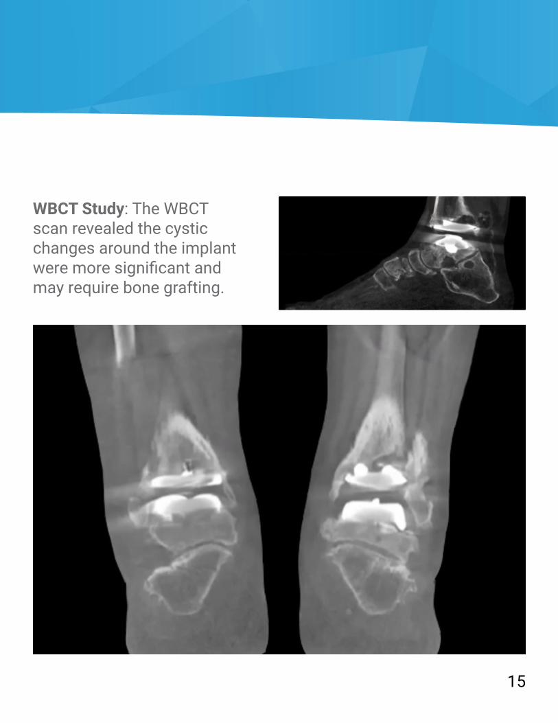
WBCT Study: The WBCT scan revealed the cystic changes around the implant were more significant and may require bone grafting.
15

Bone TumorX-Ray Study: This 18-year-old patient complained of ankle pain that had gotten progressively worse over the past two years. An X-Ray exam was ordered, but the results were inconclusive.
16
WBCT Study: The WBCT exam showed a tumor was present in the subtalar joint. The radiologist was able to estimate the approximate size of the tumor for the treating surgeon using the measurement tools in CubeVue, CurveBeam’s custom visualization software. The tumor was resected and was found to be an atypical tarsal coalition.

WBCT Study: Based on weight bearing CT, surgical plan was revised to a Lapidus bunionectomy and a 2nd and 3rd tarsometatarsal joint arthrodesis.
2
A sagittal MPR slice revealed 1st tarsometatarsal plantar gapping.
A sagittal MPR slice revealed 2nd tarsometatarsal degeneration.
Joint degeneration is much more apparent on the 3D renderings, as well as instability of the 1st, 2nd and 3rd tarsometatarsal joints.
17
Notes:____________________________________________________________________________________________________________________________________________________________________________________________________________________________________________________________________________________ __________________________________________________________________________________________________________________________________________ __________________________________________________________________________________________________________________________________________ __________________________________________________________________________________________________________________________________________ __________________________________________________________________________________________________________________________________________ __________________________________________________________________________________________________________________________________________ __________________________________________________________________________________________________________________________________________ __________________________________________________________________________________________________________________________________________ __________________________________________________________________________________________________________________________________________ __________________________________________________________________________________________________________________________________________ _____________________________________________________________________

mCurveBeam14 Rev A
About CurveBeamCurveBeam researches, designs and manufactures
cone beam CT imaging equipment for the orthopedic specialties. CurveBeam’s global headquarters are in Hatfield, Pennsylvania.
CurveBeam is privately owned and operated.
2800 Bronze Drive Suite 110, Hatfield, PA 19440267.483.8081 | [email protected] | www.curvebeam.com


