ABSTRACT. A 3MV multi-element accelerator mass spectrometer (AMS) has been installed in Xi’an, China, and prelimi-nary tests have been completed. The results of both background and precision tests for 4 nuclides are 3.1 × 10⁻¹⁶, 0.2% (14C);1.8 × 10⁻¹⁴, 1.4% (10Be); 2.3 × 10⁻¹⁵, 1.14% (26Al); and 2.0 × 10⁻¹⁴, 1.75% (129I). The unique features of this facility are thenewly developed ion source accepting solid and CO2 samples; the specially designed low-energy injector, including a “beamblanking unit” and “Q-snout”; the acceleration tube structure with the combined magnetic and electrostatic suppression; andthe function of the slit stabilization in the post-acceleration system. These features are discussed in terms of the end-user’spoint of view.
INTRODUCTION
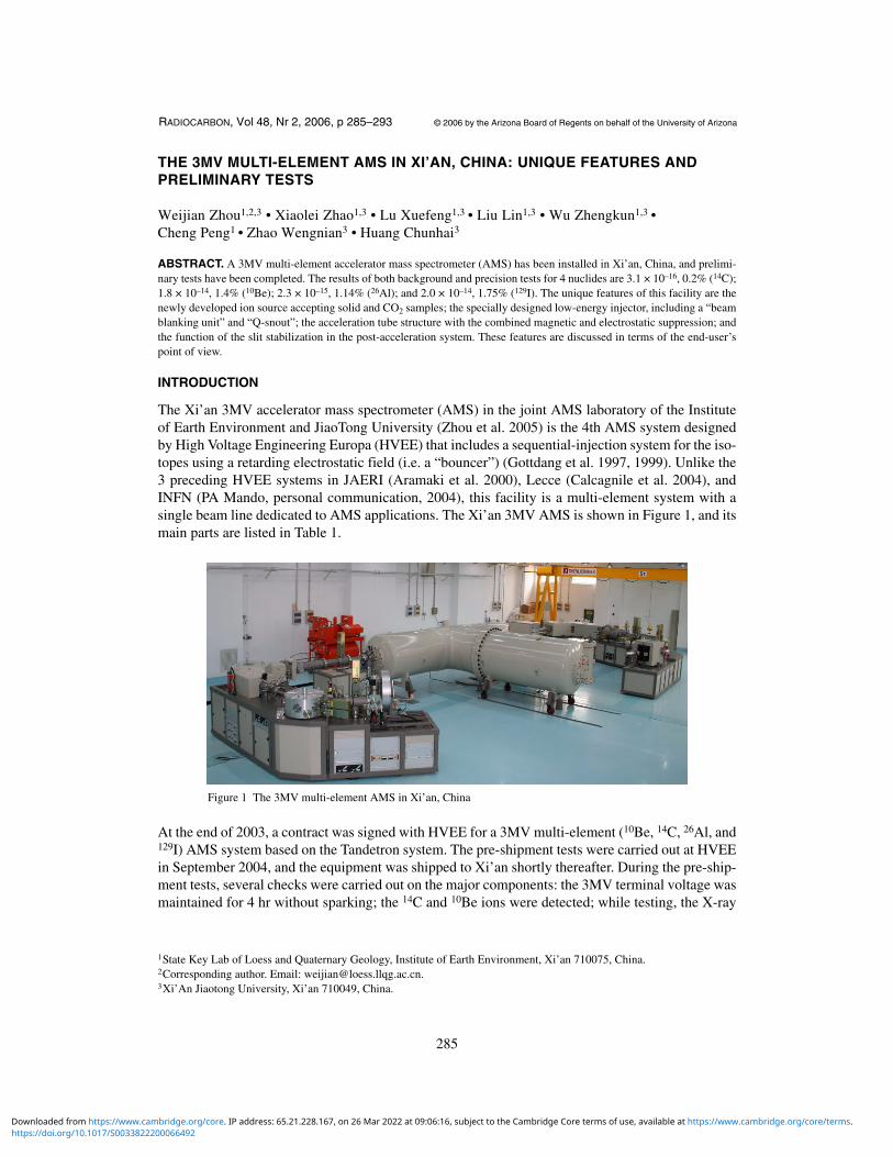
The Xi’an 3MV accelerator mass spectrometer (AMS) in the joint AMS laboratory of the Instituteof Earth Environment and JiaoTong University (Zhou et al. 2005) is the 4th AMS system designedby High Voltage Engineering Europa (HVEE) that includes a sequential-injection system for the iso-topes using a retarding electrostatic field (i.e. a “bouncer”) (Gottdang et al. 1997, 1999). Unlike the3 preceding HVEE systems in JAERI (Aramaki et al. 2000), Lecce (Calcagnile et al. 2004), andINFN (PA Mando, personal communication, 2004), this facility is a multi-element system with asingle beam line dedicated to AMS applications. The Xi’an 3MV AMS is shown in Figure 1, and itsmain parts are listed in Table 1.
At the end of 2003, a contract was signed with HVEE for a 3MV multi-element (10Be, 14C, 26Al, and129I) AMS system based on the Tandetron system. The pre-shipment tests were carried out at HVEEin September 2004, and the equipment was shipped to Xi’an shortly thereafter. During the pre-ship-ment tests, several checks were carried out on the major components: the 3MV terminal voltage wasmaintained for 4 hr without sparking; the 14C and 10Be ions were detected; while testing, the X-ray
1State Key Lab of Loess and Quaternary Geology, Institute of Earth Environment, Xi’an 710075, China.2Corresponding author. Email: [email protected]’An Jiaotong University, Xi’an 710049, China.
Figure 1 The 3MV multi-element AMS in Xi’an, China
https://doi.org/10.1017/S0033822200066492Downloaded from https://www.cambridge.org/core. IP address: 65.21.228.167, on 26 Mar 2022 at 09:06:16, subject to the Cambridge Core terms of use, available at https://www.cambridge.org/core/terms.
radiation was well below 2 µS/hr at 1 m from the tank wall; and finally, the tank was opened to ver-ify the condition of the tandem accelerator.
This Xi’an 3MV AMS facility began installation in early June 2005, and the preliminary acceptancetests have been recently carried out. This paper will describe the test results and features of the facil-ity in terms of the end-user’s points of view.
RESULTS OF THE PRELIMINARY TESTS
In addition to the retest of the 3MV terminal voltage stability for 4 hr (3.3 MV during conditioning),acceptance tests mainly focused on tests of the background for isotope ratio and precision at themodern isotope ratio for 4 radionuclides (10Be, 14C, 26Al, and 129I) operating at a terminal voltage of2.5–2.6 MV. When the precision tests were performed, the beam currents for the above 4 isotopes(analyzed currents before injection into the tandem) were 1.7 µA (Be–), 38 µA (C–), 0.25 µA (Al–),and 2.5 µA (I–), respectively. The precision measurements were demonstrated by measuring 12holders (6 for each day) provided by HVEE for modern carbon and 4 holders each for the other 3isotopes. The test procedures for the determination of both the background and precision were asfollows:
1. The AMS machine was operating for at least several hr before data was recorded;2. After pumping the AMS system down, each sample was sputter-cleaned by exposure to the
cesium beam for a period of ~5 min;3. Data acquisition began in a series of cycling measuring sequence, and each of the datum points
represents an accumulation of data taken in individual 30-s collection blocks.
The preliminary results are shown in Table 2.
The background and precision levels achieved for all 4 nuclides, except the background for beryl-lium, were better than the stated expectations of HVEE at a terminal voltage of 2.5–2.6 MV. It canbe seen from 14C precision measurements that the measured precision of 14C/12C ratios are close tothe statistical error, indicating that the AMS system was operating according to specifications. How-ever, this was not the case for the other 3 isotopes, especially the statistical error (1.56%) in the 26Alprecision measurement, which was much bigger than the precision (1.14%) of the ratio 26Al/27Al
Table 1 Major components of the HVEE 3MV multi-element AMS in Xi’an.
Ion source Cs sputter negative ion source SO-110 accepting gaseous or 50 solid targets
Detector Gas ionization chamberControl system High-level and low-level control with all signals transferred by fiber-optic lines
https://doi.org/10.1017/S0033822200066492Downloaded from https://www.cambridge.org/core. IP address: 65.21.228.167, on 26 Mar 2022 at 09:06:16, subject to the Cambridge Core terms of use, available at https://www.cambridge.org/core/terms.
due to the low aluminum current (0.25 µA), indicating other sources of error besides pure Poissonstatistics. Also, the high 14C precision obtained proves that the bouncer-based sequential injectionsystem is comparable to the recombinator-based simultaneous injection system for 14C measure-ment. Repeatability of the 14C/12C ratio during 2 consecutive days was 0.45%, indicating that theremay be other sources of error. In addition, because of the reassembling of the equipment on-site, thesystem function tests were carried out one by one according to the contract.
END-USER’S POINT OF VIEW ON FEATURES OF THE XI’AN 3MV AMS
Ion Source Accepting CO2 and Solid Samples
The Xi’an AMS adopted a HVEE/Oxford-developed sputter negative ion source (Mous et al. 1998)that directly accepts both CO2 samples and solid samples with 50 samples on the carousel. Atpresent, only the solid samples are used.
The main advantage (Mous et al. 1998) of the HVEE source (Model SO-110) is that the stainlesssteel source embodiment, including the carousel, is at ground potential during operation, avoidingthe need for a large isolation cage. All high-voltage connections to the source, including the high-voltage cable, the Cs reservoir, the CO2 feed tube, and the cooling lines, are brought together on thesource-head insulation flange, keeping to a minimum the space needed for external high-voltage iso-lation. The source-head can be pulled sideways from the source embodiment, making maintenanceeasy, and no realignment is needed after a cleaning procedure (Mous et al. 1998).
Compared with the earlier HVEE-made 846B source, an improvement of the source is the smallerholder size. An important change in the source is the removal of the computer-controlled samplemovement in the orthogonal direction on the vertical plane, which might affect the crater on thesample surface and introduce fractionation. This concern was increased by the observation that theratio of 13C/12C was changing on a long-term basis during the 14C background tests. In order to fur-ther explore the crater effect, we measured 2 modern carbon samples (an Oxalic-II acid standard[NOX] and a previously measured Chinese sugar carbon) on 2 different days to examine the changeof the isotope ratio of 13C/12C. These results are shown in both Table 3 and Figure 2. The NOX sam-
Table 2 Results of the preliminary tests of the Xi’an AMS.
Nuclides MaterialsIsotoperatio Background
Precision(statistical errors)
Graphite(1st day)
alfa graphite(provided by Leibniz-Laborfür Altersbestimmung und Isotopenforschung,Christian-Albrechts Universität of Kiel)
14C/12C13C/12C
3.1 × 10⁻¹⁶
(~65 kyr)0.2% (0.208%) at ~10–12;0.073% at ~10–12
Graphite(2nd day)
14C/12C13C/12C
0.179% (0.207%) at ~10–12;0.069% at ~10–12
Beryllium BeO(provided by High Voltage Engineering Europa B.V.)
10Be/9Be 1.8 × 10⁻¹⁴ 1.4% (0.98%) at ~10–12
Aluminum commercial powder(provided by High Voltage Engineering Europa B.V.)
26Al/27Al 2.3 × 10⁻¹⁵ 1.14% (1.56%) at ~10–11
Iodine NaI(provided by IsoTrace Lab,University of Toronto)
129I/127I 2 × 10–14 1.75% (0.57%) at ~10–10
https://doi.org/10.1017/S0033822200066492Downloaded from https://www.cambridge.org/core. IP address: 65.21.228.167, on 26 Mar 2022 at 09:06:16, subject to the Cambridge Core terms of use, available at https://www.cambridge.org/core/terms.
ple was measured from the time after it was exposed to cesium for 5 min, and the Chinese sugar car-bon sample was measured for more than 1 hr. The different curve shapes of the above 2 samplesdemonstrate the irregularity of the crater effect. The results show that the relative standard deviation(RSD) of the 13C/12C isotope ratio deteriorates during a total 14C count from 210,000 counts towards450,000 counts; the average ratio of 13C/12C changed by 0.02%.
Figure 2 The ratio 13C/12C of both the NOX sample and Chinese sugar carbon changes with timein order to explore the crater effect of the ion source. Each block represents data taken in indi-vidual collection blocks with a well-defined duration of 30 s.
Table 3 Results of the apparent crater effect tests using 2 modern samples.
New Oxalic acida
aNew Oxalic acid was measured from the time after 5 min of exposure to cesium.
225,000 counts 450,000 counts Change (%)b
bChange of the data during 450,000 14C counts relative to during about 210,000 14C counts.
13C/12C RSDc
cRelative standard deviation.
2.38 × 10⁻⁴ 2.98 × 10⁻⁴ 25.213C/12C average 1.04790% 1.04814% 0.023RSD of average 3.47 × 10⁻⁵ 3.01 × 10⁻⁵ –13.3
14C/12C RSD 1.4 × 10⁻² 1.35 × 10⁻² 0.00d
dThe statistical errors for different 14C total counts have been deducted.
14C/12C average 1.15525 × 10⁻¹² 1.15690 × 10⁻¹² 0.143RSD of average 2.04 × 10⁻³ 1.36 × 10⁻³
Blocke
eTime at which data was taken, having a well-defined duration of 30 s.
50 block 99 block
Chinese sugar Cf
fChinese sugar carbon was measured from the time after the sample was used another test of more than 1 hr.
13C/12C average 1.07294% 1.07275% 0.018RSD of average 1.76 × 10⁻⁵ 2.17 × 10⁻⁵ 23.3
14C/12C RSD 1.68 × 10⁻² 1.66 × 10⁻² 2.03d
14C/12C average 1.15866 × 10⁻¹² 1.15879 × 10⁻¹² 0.011
https://doi.org/10.1017/S0033822200066492Downloaded from https://www.cambridge.org/core. IP address: 65.21.228.167, on 26 Mar 2022 at 09:06:16, subject to the Cambridge Core terms of use, available at https://www.cambridge.org/core/terms.
Another problem of the source structure that was found is a leak that occurs while pushing eachholder in as shown in Figure 3. Though this does not affect machine operation, this design will beimproved in future.
Injector with Fast Cycling, Beam Blanking Unit, and the Q-Snout
The bouncer-based injector in the Xi’an AMS system consists of a 54° electrostatic analyzer and a90° bouncer magnet, as well as the HVEE-patented “beam blanking unit” and “Q-snout.” This is aspecial injection system developed to eliminate the shortcomings that exist in conventional bounc-ing systems, such as a reduction of accuracy. Like all modern AMS machines, the Xi’an AMS injec-tor has been optimized in its bouncing setup and electronics to enable isotope ratio measurementswith high precision (Klein et al. 2004).
Other than the simultaneous injection, the bouncer injection has put higher restrictions on the oper-ation of the ion source and the whole system. Changes in the system status, like ion source instabil-ities or other errors, may affect the measurement of the various isotopes differently when they occurfaster than the injection cycling frequency. For an accurate ratio measurement, fast cycling isrequired. A 100-Hz fast cycling frequency will be routinely used in Xi’an, which is regarded as suf-ficiently high to cope with fast source output variations (Klein et al. 2004).
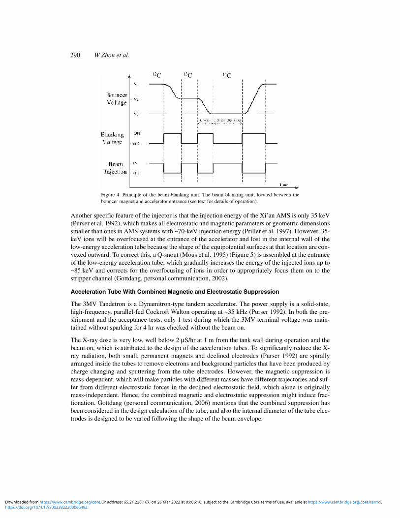
A unique feature of the HVEE injector is the beam blanking unit (Klein et al. 2004), which definesthe injection period for the different isotopes. During sequential switching between isotopes, themagnet chamber voltage requires some time to settle because the pulsing bouncer voltage is as highas 2–3 kV with a long rising time of 50–100 µs. The voltage variation during the settling time willinfluence the final precision. Such a negative effect of the settling process is eliminated by using thebeam blanking unit located between the bouncer magnet and accelerator entrance. This unit is asteerer acting as a fast switch with only a 50-ns rising time of the pulsing voltage, owing to the factthat the pulsing voltage on the unit is as low as 300 V. (Figure 4). During the bouncer voltage settlingtime, the 300-V unit voltage is on to deflect the beam out of the beam patch, and during the bouncer,voltage is stable and the unit voltage is off to let the beam pass into the accelerator.
Figure 3 Changes in source vacuum while pushing in the holder. VH1 are the vacuum gauges beneath theion source body, and VH2 are the vacuum gauges far from the source body.
https://doi.org/10.1017/S0033822200066492Downloaded from https://www.cambridge.org/core. IP address: 65.21.228.167, on 26 Mar 2022 at 09:06:16, subject to the Cambridge Core terms of use, available at https://www.cambridge.org/core/terms.
Another specific feature of the injector is that the injection energy of the Xi’an AMS is only 35 keV(Purser et al. 1992), which makes all electrostatic and magnetic parameters or geometric dimensionssmaller than ones in AMS systems with ~70-keV injection energy (Priller et al. 1997). However, 35-keV ions will be overfocused at the entrance of the accelerator and lost in the internal wall of thelow-energy acceleration tube because the shape of the equipotential surfaces at that location are con-vexed outward. To correct this, a Q-snout (Mous et al. 1995) (Figure 5) is assembled at the entranceof the low-energy acceleration tube, which gradually increases the energy of the injected ions up to~85 keV and corrects for the overfocusing of ions in order to appropriately focus them on to thestripper channel (Gottdang, personal communication, 2002).
Acceleration Tube With Combined Magnetic and Electrostatic Suppression
The 3MV Tandetron is a Dynamitron-type tandem accelerator. The power supply is a solid-state,high-frequency, parallel-fed Cockroft Walton operating at ~35 kHz (Purser 1992). In both the pre-shipment and the acceptance tests, only 1 test during which the 3MV terminal voltage was main-tained without sparking for 4 hr was checked without the beam on.
The X-ray dose is very low, well below 2 µS/hr at 1 m from the tank wall during operation and thebeam on, which is attributed to the design of the acceleration tubes. To significantly reduce the X-ray radiation, both small, permanent magnets and declined electrodes (Purser 1992) are spirallyarranged inside the tubes to remove electrons and background particles that have been produced bycharge changing and sputtering from the tube electrodes. However, the magnetic suppression ismass-dependent, which will make particles with different masses have different trajectories and suf-fer from different electrostatic forces in the declined electrostatic field, which alone is originallymass-independent. Hence, the combined magnetic and electrostatic suppression might induce frac-tionation. Gottdang (personal communication, 2006) mentions that the combined suppression hasbeen considered in the design calculation of the tube, and also the internal diameter of the tube elec-trodes is designed to be varied following the shape of the beam envelope.
Figure 4 Principle of the beam blanking unit. The beam blanking unit, located between thebouncer magnet and accelerator entrance (see text for details of operation).
14C13C12C
https://doi.org/10.1017/S0033822200066492Downloaded from https://www.cambridge.org/core. IP address: 65.21.228.167, on 26 Mar 2022 at 09:06:16, subject to the Cambridge Core terms of use, available at https://www.cambridge.org/core/terms.
The post-acceleration system is a magnetic-electrostatic-magnetic high-resolution mass spectrome-ter. The main component is the 115° magnet, and its maximum magnetic field is 1.144 T. However,the estimated magnetic field required for 3MV 129I+5 acceleration is about 1.14 T, so these studieswill be performed at 2.5 MV.
The 65° electrostatic analyzer has a very large curvature radius (1700 mm), so it is highly energydispersive and causes the separation between 10Be+3 and 10B+3 ions to be 3.6 cm in front of the detec-tor (Mous, personal communication, 2002) after passing through a 500-nm Si3N4 foil located infront of the 65° electrostatic analyzer. This plays an effective role in reducing the level of scattered10B+3 during counting.
The original motivation for “slit stabilization” after the high-energy analyzing (115°) magnet is toincrease the stability of the beam energy by stabilizing the terminal voltage, which is controlled bythe feedback of the slit error signals induced by the beam of the stable isotopes. Such a stabilizingfunction can only be successful when the slit error signals are induced due to a change of the termi-nal voltage. If the slit error signals are induced due to a change of some parameter, the terminal volt-age would be adjusted to compensate this parameter change and to fix the position of the stable iso-tope beam inside the slit system. This phenomenon was discovered in the course of performing allthe precision tests when the maximum fluctuations of the terminal voltage were ~4–6 kV, rangingwithin 2498~2503 kV (14C), 2499~2503 kV (10Be), 2599~2605 kV(26Al), and 2499~2503 kV (129I),though the required precisions were all obtained. Therefore, the real function of the slit stabilizationis to precisely measure the beam currents of the stable isotope and to improve the measurement ofthe isotope ratio rather than only to stabilize the terminal voltage. If the terminal voltage changes,the slit stabilization will be more effective functioning in the simultaneous injection mode than inthe sequential injection mode. The reason is that the slit error signal induced by the stable isotope
Figure 5 Principle of the Q-snout. Ions with 35 keV will be overfocused at the entrance of the accelerator and lost inthe internal wall of the low-energy acceleration tube because the shape of the equipotential surfaces at that locationare convexed outward.
https://doi.org/10.1017/S0033822200066492Downloaded from https://www.cambridge.org/core. IP address: 65.21.228.167, on 26 Mar 2022 at 09:06:16, subject to the Cambridge Core terms of use, available at https://www.cambridge.org/core/terms.
beam is picked up at 100% of the time in the simultaneous injection mode, whereas at only 1% ofthe time of each cycling in the sequential injection mode. Nevertheless, the slit stabilization is stillfunctioning in our AMS system, owing to the fact that our injection system is working with a fastcycling of 100 kHz.
“Flat top” transmission is carried out in the HVEE-designed Xi’an 3MV AMS by enlarging thediameter of the acceleration tube, thus making the diameter of the stripper channel twice the size ofthe beam spot (Purser 1988), opening the adjustable slits as wide as possible so as not to interceptthe ions, and modeling all of the electric and magnetic parameters using the “Trace” program. As aresult, the fractionation has been minimized in the HVEE design when a minor fluctuation of theelectric or magnetic parameter occurs. This design even allows for the electrostatic settings toremain the same when analyzing negative molecular ions, such as BeO–, where the energy differ-ence between the 10Be+3 and 9Be+3 ions is as high as 0.73%.
CONCLUSION
Preliminary tests have convinced us that the Xi’an 3MV AMS can already serve our purposes at aterminal voltage of 2.5–2.6 MV. We hope to improve the background of beryllium, which dependson some factors, including sample preparation. The tests show that a bouncer-based AMS can reachthe same high 14C precision as a recombinator-based AMS, and the precision of 10Be, 26Al, and 129Ialso have reached levels better than we expected. Further tests will explore the maximum potentialof the facility for 129I+5 measurements and will measure the 3 nuclides 10Be, 26Al, and 129I byincreasing the terminal voltage towards 3 MV. Finally, there are some improvements needed, suchas the last slit in front of the detector, which will be changed into an adjustable slit to better enablemulti-element analyses.
ACKNOWLEDGMENTS
The authors are deeply indebted to Prof Yongxiang Lu, Prof Yiyu Chen, Prof Jiayang Li, Prof Zhish-eng An, Prof Nanning Zheng, Dr Xu Ping, and Dr Tian Dongsheng for their strong support andsupervision over all aspects of this project. We are also grateful to Profs Maobai Chen, Liping Yang,Dr Xiaolei Zhao, and Prof Zhenhao Liu for their concrete technical support and advice. Many well-known AMS experts have provided us with valuable suggestions and technical information in ourplanning stage; we would like to express our sincere acknowledgement to Profs and Drs ZY Guo,KX Liu, CD Shen, SS Jiang, W Kutschera, A Priller, D Donahue, AJT Jull, G Burr, W Beck, MNadeau, G Raisbeck, T Kitamura, and E Cottereau. Finally, we would like to thank the physicists atHVEE; D Mous, A Gottdang, and K Klein for their excellent design; and J Bergen, SA Miedema,and MC Sorby for their careful and skilled work on installation and testing. This project is supportedby funding from the Chinese Academy of Sciences, Ministry of Education, Ministry of Science andTechnology, and NSFC40531003, 40523002 & 40121303, and NBRPC2004CB720200 grants.
REFERENCES
Aramaki T, Mizushima T, Mizutani Y, Yamamoto T, To-gawa O, Kabuto S, Kuji T, Gottdang A, Klein M,Mous DJW. 2000. The AMS facility at the JapanAtomic Energy Research Institute. Nuclear Instru-ments and Methods in Physics Research. B 172:18–23.
Calcagnile L, Quarta G, D’Elia M, Gottdang A, Klein M,Mous D W. 2004. Radiocarbon precision tests at the
Lecce AMS facility using a sequential injection sys-tem. Nuclear Instruments and Methods in Physics Re-search B 215:561–4.
Gottdang A, Mous DW. 1997. The novel HVEE multi-el-ement AMS system. Nuclear Instruments and Meth-ods in Physics Research B 123:163–6.
Gottdang A, Mous DW. 1999. Characteristics of theHVEE 3MV multi-element AMS system. In: Duggan
https://doi.org/10.1017/S0033822200066492Downloaded from https://www.cambridge.org/core. IP address: 65.21.228.167, on 26 Mar 2022 at 09:06:16, subject to the Cambridge Core terms of use, available at https://www.cambridge.org/core/terms.
JL, Morgan IL, editors. Proceedings of Application ofAccelerators in Research and Industry. CP475.Melville, USA: American Institute of Physics. p 652–6.
Klein M, Mous DJW, Gottdang A. 2004. Fast and accu-rate sequential injection AMS with gated Faraday cupcurrent measurement. Radiocarbon 46(1):77–82.
Mous DJW, Gottdang A, Van den Brock R, Haitsma RG.1995. Recent developments at HVEE. Nuclear Instru-ments and Methods in Physics Research B 99:697–700.
Mous DJW, Fokker W, van den Broek R, Koopmans R,Bronk Ramsey C, Hedges REM. 1998. An ion sourcefor the HVEE 14C isotope ratio mass spectrometer forbiomedical applications. Radiocarbon 40(1):283–8.
Nadeau M-J, Schleicher M, Grootes PM, Erlenkeuser H,Gottdang A, Mous DJW, Sarnthein JM, Willkomm H.1997. The Leibniz-Labor AMS facility at the Chris-tian-Albrechts University, Kiel, Germany. Nuclear In-struments and Methods in Physics Research B 123:22–30.
Nakamura T, Niu E, Oda H, Ikeda A, Minami M, Taka-hashi H, Adachi M, Pals L, Gottdang A, Suya N. 2000.The HVEE Tandetron AMS system at Nagoya Univer-
sity. Nuclear Instruments and Methods in Physics Re-search B 172:52–7.
Priller A, Golser R, Hille P, Kutschera W, Rom W, SteierP, Wallner A, Wild E. 1997. First performance tests ofVERA. Nuclear Instruments and Methods in PhysicsResearch B 123:193–8.
Purser KH. 1992. A high throughput 14C acceleratormass spectrometer. Radiocarbon 34(3):458–67.
Purser KH, Smick T. 1988. A third generation 14C accel-erator mass spectrometer. Nuclear Instruments andMethods in Physics Research B 35:284–91.
Purser KH, Smick TH, Purser RK. 1990. A precision 14Caccelerator mass spectrometer. Nuclear Instrumentsand Methods in Physics Research B 52:263–8.
van der Plicht J, Aerts A, Wijma S, Zondervan A. 1995.First results from the Groningen AMS facility. Radio-carbon 37(2):657–61.
Zhou WJ, Liu L, Zhao XL, Lu XF, Wu ZK, Xi G, YangLP, Chen MB. Forthcoming. Xi’an-AMS: a multi-ele-ment system at the Xi’an AMS Center. Proceedings ofthe 10th International Conference on AcceleratorMass Spectrometry. Nuclear Instruments and Meth-ods in Physics Research B.
https://doi.org/10.1017/S0033822200066492Downloaded from https://www.cambridge.org/core. IP address: 65.21.228.167, on 26 Mar 2022 at 09:06:16, subject to the Cambridge Core terms of use, available at https://www.cambridge.org/core/terms.