41
The Application of Causal Analysis Techniques for Computer-Related Mishaps Chris Johnson University of Glasgow, Scotland. http://www.dcs.gla.ac.uk/~johnson SAFECOMP: 26 th September 2003
| Date post: | 16-Dec-2015 |
| Category: |
Documents |
| Upload: | theodora-glenn |
| View: | 223 times |
| Download: | 2 times |

The Application of Causal Analysis Techniques for Computer-Related Mishaps
Chris Johnson
University of Glasgow, Scotland.http://www.dcs.gla.ac.uk/~johnson
SAFECOMP: 26th September 2003

Acknowledgements
HSE: Mark Bowell, Ray Ward.
Adelard: George Clelland, Peter Bishop, Luke Emmett, Sofia Guerra, Robin Bloomfield.
Blacksafe Consulting: Bill Black.
Glasgow University: Chris Johnson.
Look, I’m not blaming you, I’m just suing you…

A: Detection and Notifi cation
B: Data gathering
C: Reconstruction
D: Analysis
E: Recommendations and Monitoring
F: Reporting and Exchange

• Author bias: – individuals reluctant to accept findings
they did not produce.
• Confidence bias: – people trust those with most
confidence in their techniques.
• Hindesight bias: – investigators use information
unavailable to people in incident.
• Judgement bias: – investigators reach decision within a
constrained time period.
• Political bias: – high status member has influence by
status not judgement itself…
“At this point in the meeting, I’d like to shift the blame from me onto
someone else…”
Bias

0
1
2
3
4
5
6
7
8
9
10
Could the
incident have
been anticipated
by risk
managers?
Could the
incident have
been anticipated
by participants?
How severe was
the incident?
How much is
such an incident
f eared by staff ?
How confi dent
are you in
avoiding such
incidents?
How risky was
the incident?
How easy is it to
control the
outcome of such
incidents?
How visible was
the incident?
How much eff ort
is necessary to
avoid f uture
incidents?
bad
good


The Sunday Telegraph, September 7th, 2003, page 33.
Does this really look like me?
Fish accidents?
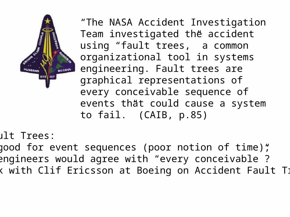
“The NASA Accident Investigation Team investigated the accident using “fault trees,” a common organizational tool in systems engineering. Fault trees are graphical representations of every conceivable sequence of events that could cause a system to fail.” (CAIB, p.85)
“The NASA Accident Investigation Team investigated the accident using “fault trees,” a common organizational tool in systems engineering. Fault trees are graphical representations of every conceivable sequence of events that could cause a system to fail.” (CAIB, p.85)
But…Fault Trees:- not good for event sequences (poor notion of time);- few engineers would agree with “every conceivable”? * work with Clif Ericsson at Boeing on Accident Fault Trees *

Control system closes valve A, starves debutanizer.
Also closes valve B, heating raises debutanizer pressure.
Opens valve A, debutanizer flow restored.
Valve B should open to splitter.
Operators see misleading signals, valve B shown open.
Debutanizer fills while naptha splitter empties.
Debutanizer
Naptha Splitter
Deethaniser Debutanizer
overhead accumulator
Valve A
Valve B
Valve C Flare lines
Wet gas compressor
Flare knockout
drum
Flare

Motivation: Milford Haven
Separate displays.
Didnt check status of valve B, operators open valve C.
Debutanizer vents to flare, wet gas compressor restarts.
Should increase flow but increases debutanizer pressure.
Material vents to flare drum, corroded discharge breaks.
20 tonnes of hydrocarbon ignites, damage > £50 million.

Motivation: Milford Haven• Human ‘Error’ and Plant Design/Operation
“Operators were not provided with information systems configured to help them identify the root cause of such problems. Secondly, the preparation of shift operators and supervisors for dealing with a sustained upset and therefore stressful situation was inadequate.
• Safety Management Systems“… the company’s crucial safety management systems were not adequately performing their
function. Examples are the systems for modification and inspection. Company was unaware of defects in safety management systems because its monitoring of their performance did not effective highlight problems.”
• Risk Assessment
“…3 years before a modification was carried out so automated high-capacity discharge pumps no longer automatically started to move excess to slops from flare discharge tank. Instead, low capacity pumps recycle material back to production process. Valves had to be operated manually if high-capacity pumping to slops needed but this was seldom (never?) practiced”.

Elicitation and Reconstruction

08.30: Electrical storm causes power disruptions
08.30: Visible & audible alarms as vacuum gas oil flow into FCCU falls below acceptable limit.
08.33: Operators respond by manually reducing flow to deethaniser using computer panel in control room.
08.39: Deethanizer rapidly empties so E/ E/ PES responds by closing output to deethaniser.
08.34: ‘Temperamental’ deethanizer valve closes completely
Alarm system
Deethanizer
Operators
Environment
08.39: Debutanizer cascades alarm and closes its output valve as level f alls in debutanizer.
Debutanizer 08.46: Debutanizer pressure rises rapidly as it now contains vaporized materials that had been received f rom deethaniser
Flare system 08.47 Materials vent to fl are system, some returned to process via recovery system.
09.12: Debutanizer outlet valve (B) erroneously shown to have been opened by the E/ E/ PES as liquid levels are reestablished.
09.13+: Liquids accumulate in deethaniser and downstream to debutaniser as valve B f ails shut
09.12: E/ E/ PES shows that debutanizer outlet valve (B) opened by flow indication and debutanizer level below maximum due to f ailed sensor .
08.39: Debutanizer cascades alarm and closes output valve as level f alls in debutanizer.
08.40+: Naptha splitter cascades alarm as level f alls in supply f rom debutanizer.

20 tonnes discharged
Hydrocarcbon explodes.
I nitial overhead accumulator material sent to flare.
Compressor restarts pressure increase in debutanizer
Users open valve C (2nd time).
Compressor trips (second time).
Further overhead accumulator material sent to flare.
Liquid f orced f rom full flare drum to corroded discharge pipe.
Alarm for flare drum is activated.
Control system (?) opens valve A
Debutan receives further flow.
Command to open valve B fails.
Operators receive wrong signal valve B open
Debutaniser fi lls with
liquid
Users open valve C (fi rst time)
Liquid in overhead accumul. flows into recovery section.
Debutanizer logged
Debutanizer vents to flare
Compressortrips (fi rst time).
Fire hoses used to drain dry stage material
to flare.
Outcome Event
Mishap Event
Direct f actor
I ndirect f actor
Key
Modifi cation to flare drum pump prevents excess being pumped
to storage tanks.
Automated system that would pump excess to ‘slops’ now requires manual intervention
Operator f ails to check status of valve
B.
Operators preoccupied by controlling heat transfer process
between components.
Operators f ail to attend to high-level
alarm f rom flare drum for 25 minutes prior to
explosion.
Maintenance failure leaves senor-
indicating flow and level in debutanizer was believed to give erroneous indication
below maximum. Pump slowly discharges
automatically f rom flare drum back into secondary
overhead accumulation.
Desire to reduce load on recycling plant
during normal operations, pumps operate to slops at f ull capacity only if manual
valve is opened
Manual operation of Valve to pump at high
capacity f rom flare drum to slops not practiced.
Operators f ail to realize potential
danger f rom flare overflow
Design assumption in automated control system logic that if
discharge rate increased then it
would outstrip increases in input so no control over input in single control loop.
No second, back-up feedback control loop to ensure input flow reduced or shut off
when material
accumulates.
Poor maintenance procedures (apparent in f ailed sensors and other components).
Alarms cascade with low prioritization and require explicit acknowledgement by operators.
Fractional distillation uses 1 main input to produce 5 product streams. I nformation on accumulated outputs of each stream distributed across
several control display units.
Poor display design: no single display provides overview of
FCCU process; lack of colour to indicate status and reliance on
presentation of discrete values.
E/ E/ PES Mishap Event

20 tonnes discharged
Hydrocarcbon explodes.
Users open valve C (2nd time).
Compressor trips (second time).
Further overhead accumulator material sent to flare.
Liquid forced f rom full flare drum to corroded discharge pipe.
Modifi cation to flare drum pump prevents excess being pumped
to storage tanks.
Automated system that would pump excess to ‘slops’ now requires manual intervention
Operators preoccupied by controlling heat transfer process
between components.
Operators fail to attend to high-level
alarm f rom flare drum for 25 minutes prior to
explosion.
Pump slowly discharges
automatically f rom flare drum back into secondary
overhead accumulation.
Desire to reduce load on recycling plant
during normal operations, pumps operate to slops at full capacity only if manual
valve is opened
Manual operation of Valve to pump at high
capacity f rom flare drum to slops not practiced.
Alarms cascade with low prioritization and require explicit acknowledgement by operators.
Fractional distillation uses 1 main input to produce 5 product streams. I nformation on accumulated outputs of each stream distributed across
several control display units.
Poor display design: no single display provides overview of
FCCU process; lack of colour to indicate status and reliance on presentation of discrete values.
Outcome Event
Mishap Event
Direct f actor
I ndirect f actor
Key
E/ E/ PES Mishap Event

Tier Causal Factors Cause
5: SeniorManagement(J PL LaboratoryDirector and MarsProgram Offi ceDirector)
Minimal number of developmentstaff transition to operations.
Decision not to perf orm an a prioranalysis of what could go wrong onthe MCO.
Limited independent testing of theground-based SM_Forces routine.
Feeling that orbiting Mars isroutine.
I nsular relationship with LMAprevented adequate riskassessment and mitigatedagainst independent reviews.
4: MiddleManagement(Climate OrbiterProject Manager)
TCM-5 is discussed but notexecuted.
3: LowerManagement(Flight OperationsManager/FlightDevelopmentManager)
SM_Forces routines are writtenusing I mperial and not metric unitsf or thruster perf ormance.
Decision to reject barbecue mode.
Decision to use asymmetrical solararray.
Tier Analysis: JPL

Flow Charts

Event
Oversights/ Omissions Assumed Risks
What? Specifics LTA Why? Management LTA
Policy LTA I mplementation LTA Risk assessment LTAAccident Corrective Action LTA
Hazard Barrier/ ControlLTA
Target RecoveryLTA
Did notprevent 2nd
accident
Emergencyactions LTA
RelationsLTA
Goals LTA Tech. I nf o.Systems LTA
Hazard analysisLTA
Safety ProgramReview LTA
Controls LTA Barriers LTA Design and development plan LTA Concepts and requirements LTA
Tech. I nf o.LTA
OperabilityLTA
MaintenanceLTA
I nspectionLTA
Higher supervisionLTA
Design basisLTA
HumanFactors LTA
MaintenancePlan LTA
I nspectionPlan LTA
General DesignProcess LTA
Other SupportSystems LTA
OperationalSpecification LTA
MotivationLTA
ProceduresLTA
QualificationsLTA
SupervisionLTA
TrainingLTA
MonitoringPoints LTA
Monitor LTA TrendingLTA
AnalysisLTA
Corrective ActionTrigger LTA
CommunicationLTA
Knowledge LTA
1st LineSupervision LTA
SupervisorsTraining LTA
Time LTA PerformanceError
Did notcorrect
Did notdetect
EmergencyTask Non-task
AssignmentLTA
BriefingLTA
ProcedureLTA
WorkerProblem
None LTASafetyAnalysis
Did not use Aberrantbehaviour
SelectionLTA
Training LTA MotivationLTA
Key
AND gate
OR gate
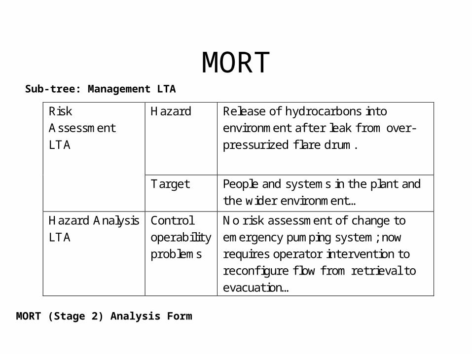
MORTSub-tree: Management LTA
MORT (Stage 2) Analysis Form
Hazard Release of hydrocarbons into environment af ter leak f rom over-pressurized flare drum.
Risk Assessment LTA
Target People and systems in the plant and the wider environment…
Hazard Analysis LTA
Control operability problems
No risk assessment of change to emergency pumping system; now requires operator intervention to reconfi gure flow f rom retrieval to evacuation…

PRISMA
• Anaesthesia study:– 15 incidents:– 78 root causes (5.2 ave);– 27% organisational
causes;– 40% (direct) human
causes;– 26% technical causes.
• A&E study:– 19 incidents:– 93 root causes (4.9 ave);– 45% organisational causes;– 41% (direct) human causes.

Hydrocarbons released f rom flare drum.
Build up of excess material in the flare
lines and drum
Automatic high-capacity discharge pumps fail to
clear flare drum to slops.
Hydrocarbons continue to be pumped into debutaniser even
though valve B is closed
Operators open valve C releasingmaterial into wet gas compressor
causing trips and venting to flare..
System shows valve B is open
though it remains closed.
Operators f orget to reconfigure pumps f rom recovery function that
f eedsback excess material into production line.
Automated system to start high-
capacity pumps is disabled.
I nadequate training of correct response to
emergency conditions including pump
reconfiguration.
Operators have to recognise and
acknowledge 275 alarms in the last 11 minutes before the explosion.
Corrosion in discharge pipe f rom
the flare drum.
Display design makes it diffi cult to diagnose cause
of problem.
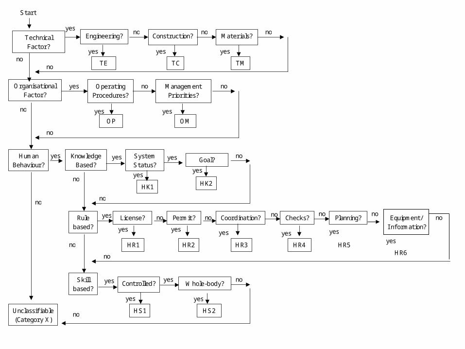
TechnicalFactor?
Engineering? Construction? Materials?yes
yes yes
no no
TCTE
Start
OrganisationalFactor?
no
OperatingProcedures?
ManagementPriorities?
yes yes
yes no
OMOP
no
HumanBehaviour?
SystemStatus?
no
Rulebased?
no
Skillbased?
Unclassifiable(Category X)
no
Goal?
yes
yes
HK2
no
License?
yes
yes no
HR1
Permit?
yes
HR2
Coordination?
yes
no
HR3
Checks?
yes
no
HR4
no
no
Planning?
yes
no
HR5
noKnowledgeBased?
yes
yes
TM
no
no
yes
yes
HK1
no
Controlled? Whole-body?
yes
yes
HS2
noyes
yes
HS1no
noEquipment/I nformation?
yes
no
HR6

Example PRISMA Classification/Action MatrixExternal Factors(O-EX)
KnowledgeTransf er (OK)
Operatingprocedures (OP) &
Manag. priorities(OM)
Culture (OC)
I nter-departmentalcommunication
X
Training andcoaching
X
Procedures andprotocols
X
Bottom-upcommunication
X
Maximisereflexivity
X
Accident Models
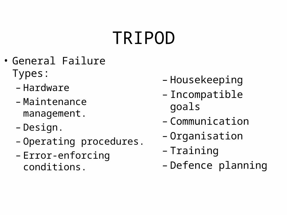
TRIPOD• General Failure Types:
– Hardware– Maintenance
management. – Design. – Operating procedures.– Error-enforcing
conditions.
– Housekeeping– Incompatible goals– Communication– Organisation– Training– Defence planning
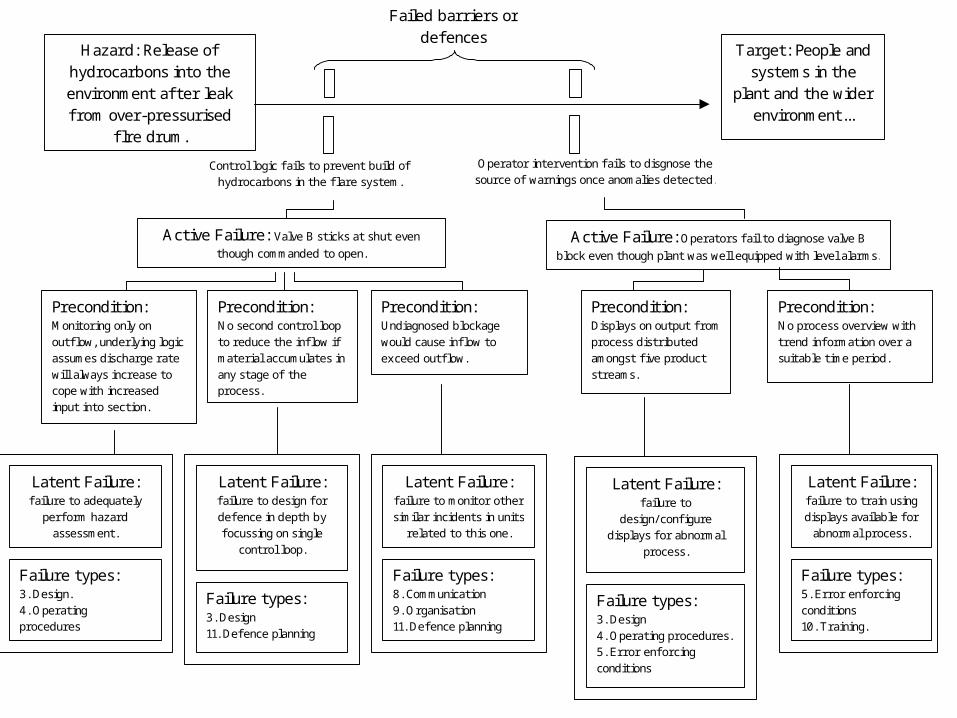
Active Failure: Valve B sticks at shut even
though commanded to open.
Hazard: Release of hydrocarbons into the environment af ter leak f rom over-pressurised
fl re drum.
Target: People and systems in the
plant and the wider environment...
Failed barriers or defences
Active Failure: Operators f ail to diagnose valve B
block even though plant was well equipped with level alarms.
Control logic f ails to prevent build of hydrocarbons in the flare system.
Operator intervention f ails to disgnose the source of warnings once anomalies detected.
Precondition: Undiagnosed blockage would cause inflow to exceed outflow.
Precondition: Monitoring only on outf low, underlying logic assumes discharge rate will always increase to cope with increased input into section.
Precondition: No second control loop to reduce the inflow if material accumulates in any stage of the process.
Precondition: Displays on output f rom process distributed amongst five product streams.
Precondition: No process overview with trend information over a suitable time period.
Latent Failure: f ailure to design f or defence in depth by focussing on single
control loop.
Failure types: 3. Design 11. Defence planning
Latent Failure: f ailure to adequately
perform hazard assessment.
Failure types: 3. Design. 4. Operating procedures
Latent Failure: f ailure to monitor other similar incidents in units
related to this one.
Failure types: 8. Communication 9. Organisation 11. Defence planning
Latent Failure: f ailure to
design/ configure displays f or abnormal
process.
Failure types: 3. Design 4. Operating procedures. 5. Error enf orcing conditions
Latent Failure: f ailure to train using displays available f or
abnormal process.
Failure types: 5. Error enf orcing conditions 10. Training.

Regulators
Debutanizer Deethanizer
Operator
Control system
Flare stack
Reclamation pumps
High capacity discharge
pumps
‘Slops’ storage tanks
Flare drum
Flare drum alarm
Valve B
Valve C
Valve A Naptha splitter
Debutanizer overhead
accumulator
Maintenance personnel*
Compressor
Discharge pipe
Training simulator
Line supervisors
Site Managers
Fire Service
Off -site Managers
Operating Company
Engineering project manager
Technical experts
External product auditors
E/ E/ PES Supplier/ Design team
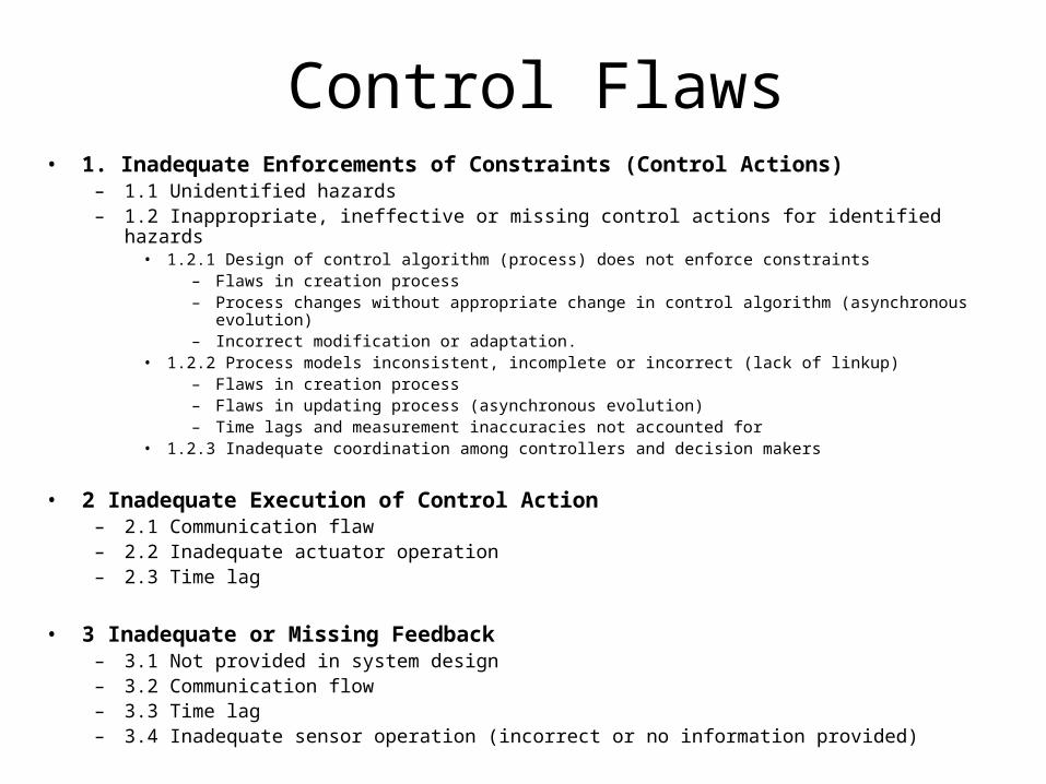
Control Flaws• 1. Inadequate Enforcements of Constraints (Control Actions)
– 1.1 Unidentified hazards– 1.2 Inappropriate, ineffective or missing control actions for identified hazards
• 1.2.1 Design of control algorithm (process) does not enforce constraints– Flaws in creation process– Process changes without appropriate change in control algorithm (asynchronous
evolution)– Incorrect modification or adaptation.
• 1.2.2 Process models inconsistent, incomplete or incorrect (lack of linkup)– Flaws in creation process– Flaws in updating process (asynchronous evolution)– Time lags and measurement inaccuracies not accounted for
• 1.2.3 Inadequate coordination among controllers and decision makers
• 2 Inadequate Execution of Control Action– 2.1 Communication flaw– 2.2 Inadequate actuator operation– 2.3 Time lag
• 3 Inadequate or Missing Feedback– 3.1 Not provided in system design– 3.2 Communication flow– 3.3 Time lag– 3.4 Inadequate sensor operation (incorrect or no information provided)

Control Relationship Constraint violation J ustifi cation
[Operator-> Control System]
1.2 I nappropriate, ineff ective or missing control action f or identified hazard
Operator f ailed to check valve B and instead opened valve C – repeatedly f orcing hydrocarbons into the flare system.
3.4 I nadequate sensor operation
System failed to show correct state of valve B. [Control System -> Operator]
3.2 Communication fl ow System failed to provide necessary process overview.
Operator
Control system
Maintenance personnel*
Training simulator
Line supervisors
Site Managers
Fire Service
Off -site Managers
Operating Company

Argumentation Techniques
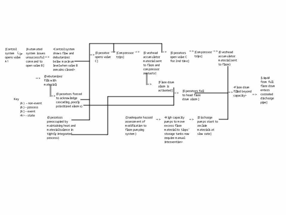
[Control
system opens valve A]
[Automated system issues unsuccessful command to open valve B]
[Liquid f rom full flare drum enters corroded discharge pipe]
Key (A) – non-event {A} – process [A] – event <A> - state
<Flare drum fi lled beyond capacity>
[Operators f ail to head flare drum alarm]
{Operators preoccupied by maintaining heat and material balance in tightly integrated process}
{Operators f orced to acknowledge cascading, poorly prioritized alarms}
[Operators open valve C for 2nd time]
[Compressor trips]
<Control system shows flow and debutanizer below maximum level when valve B remains closed>
[Discharge pumps start to reclaim materials at slow rate]
<High capacity pumps to move excess flare material to ‘slops’ storage tanks now require manual intervention>
{I nadequate hazard assessment of modification to flare pumping system}
{Debutanizer fi lls with material}
[Operator opens valve C]
[Overhead accumulator material sent to flare and compressor restarts]
[Compressor trips]
{Overhead accumulator material sent to flare}
[Flare drum alarm is activated]

Conclusions
• Several classes of causal analysis techniques for E/E/PES:– Elicitation Techniques (e.g., Barrier Analysis); – Event-based techniques (e.g., Accident fault trees); – Flow Charts (e.g., PRISMA); – Accident Models (e.g., control theory models in STAMP); – Argumentation Techniques (e.g., counterfactual WBA).
• How do we assess them?– investment, (i.e., training and time required to apply them); – consistency of individuals applying approach to same
incident. – degree of support for recommendations/redesign?

Conclusions
• Can technique analyze failures at every stage of E/E/PES development? – Need to identify all candidate stages of development….– Assess techniques against IEC 61508 development model. – Other standards/models might have been used.
• Begin with subjective assessments + peer review (NTSB and NASA).
• Currently validating against industrial experience.
• Methodological problems (who has used more than 2 techniques?).

Elicitation and Analysis techniques
Event Based Techniques
Flowcharts and taxonomies
Accident Models Argumentation Techniques
Barrier Anal.
Change Anal.
Timelines Accident Fault Trees
MORT PRISMA TRIPOD STAMP WBA CAE
IEC 61508 Lifecycle phase Concept F F U U F P F P U F
Scope F F U U F P F P U F Risk Assessment P P P P F P P F U F
Safety Requirement
F F U U P P F F U F
Allocation F P P U P P F P U U Planning of Validation,
Operation & maintenance
U P P P F F U P P U
Realisation U F F P U P U F F U Installation / Commission
U P F P P P P P F P
Validation P P F P P P P U F P Operation & Maintenance
P F F P P P F F F P
Modification U F F P P P U F F P IEC 61508 Common Requirements
Competency P P P P P P F P P P Lifecycle U P P P P P P P P P
Verification P P P P P F P P P P Safety
management P P P P P P P P P P
Document. P P P P P P P P P P Functional safety
assessment P P P P P P P P P P
Key: (U)nsupported, (P)artially supported, (F)ully supported
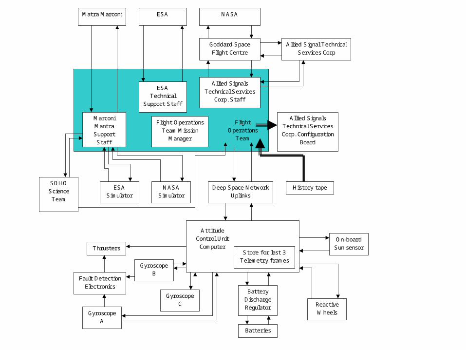
NASA
Flight Operations
Team
Goddard Space Flight Centre
SOHO Science Team
ESA Simulator
Allied Signal Technical Services Corp
Marconi Mantra Support Staff
ESA Technical
Support Staff
Allied Signals Technical Services Corp. Confi guration
Board
ESA Matra Marconi
Allied Signals Technical Services
Corp. Staff
NASA Simulator
Flight Operations Team Mission
Manager
Store for last 3 Telemetry f rames
Attitude Control Unit Computer
Deep Space Network Uplinks
History tape
Gyroscope A
Gyroscope B
Gyroscope C
Fault Detection Electronics
Thrusters
Battery Discharge Regulator
Batteries
On-board Sun sensor
Reactive Wheels
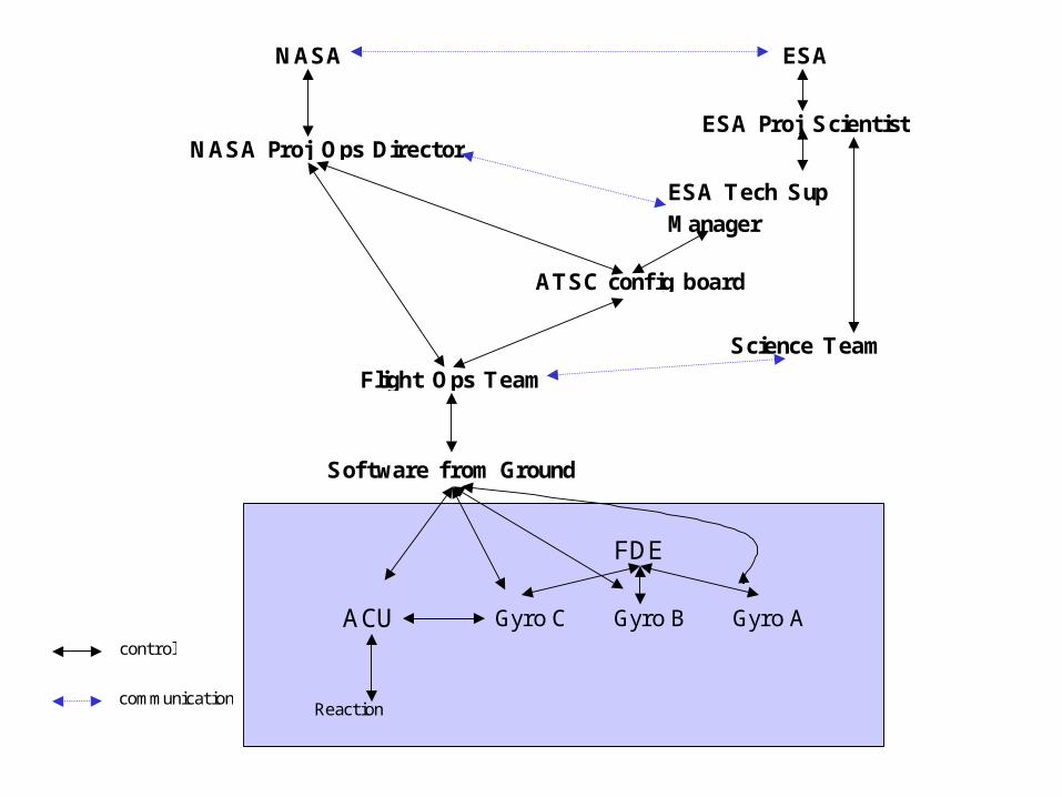
ACU
Reaction wheels
FDE
Gyro C Gyro B Gyro A
Software from Ground
Flight Ops Team
ESA Tech Sup Manager
ATSC config board
ESA Proj Scientist
Science Team
NASA Proj Ops Director
NASA ESA
control
communication
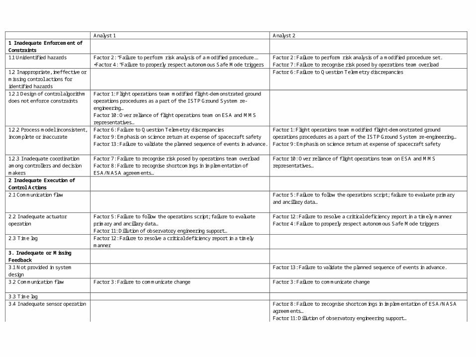
Analyst 1 Analyst 2
1 I nadequate Enforcement of Constraints
1.1 Unidentifi ed hazards Factor 2: “Failure to perf orm risk analysis of a modifi ed procedure... •Factor 4: “Failure to properly respect autonomous Safe Mode triggers
Factor 2: Failure to perf orm risk analysis of a modifi ed procedure set. Factor 7: Failure to recognise risk posed by operations team overload
1.2 I nappropriate, ineff ective or missing control actions f or identifi ed hazards
Factor 6: Failure to Question Telemetry discrepancies
1.2.1 Design of control algorithm does not enf orce constraints
Factor 1: Flight operations team modifi ed fl ight-demonstrated ground operations procedures as a part of the I STP Ground System re-engineering… Factor 10: Over reliance of fl ight operations team on ESA and MMS representatives…
1.2.2 Process model inconsistent, incomplete or inaccurate
Factor 6: Failure to Question Telemetry discrepancies Factor 9: Emphasis on science return at expense of spacecraf t safety Factor 13: Failure to validate the planned sequence of events in advance.
Factor 1: Flight operations team modifi ed fl ight-demonstrated ground operations procedures as a part of the I STP Ground System re-engineering… Factor 9: Emphasis on science return at expense of spacecraf t safety
1.2.3 I nadequate coordination among controllers and decision makers
Factor 7: Failure to recognise risk posed by operations team overload Factor 8: Failure to recognise shortcomings in implementation of ESA/ NASA agreements…
Factor 10: Over reliance of fl ight operations team on ESA and MMS representatives…
2 I nadequate Execution of Control Actions
2.1 Communication fl aw Factor 5: Failure to f ollow the operations script; f ailure to evaluate primary and ancillary data…
2.2 I nadequate actuator operation
Factor 5: Failure to f ollow the operations script; f ailure to evaluate primary and ancillary data… Factor 11: Dillution of observatory engineering support…
Factor 12: Failure to resolve a critical defi ciency report in a timely manner Factor 4: Failure to properly respect autonomous Safe Mode triggers
2.3 Time lag Factor 12: Failure to resolve a critical defi ciency report in a timely manner
3. I nadequate or Missing Feedback
3.1 Not provided in system design
Factor 13: Failure to validate the planned sequence of events in advance.
3.2 Communication fl aw Factor 3: Failure to communicate change
Factor 3: Failure to communicate change
3.3 Time lag 3.4 I nadequate sensor operation Factor 8: Failure to recognise shortcomings in implementation of ESA/ NASA
agreements… Factor 11: Dillution of observatory engineering support…
Questions


