384 The application of phase-contrast microscopy to mineralogy and petrology. (With Plates XXII-XXIV.) By FRANK SMITHSON, D.Sc., F.G.S., F.R.M.S. [Read June 24, 1948.] Introduction p HASE-CONTRAST methods in microscopy appear to have been developed mainly with the intention of applying them to biological subjects, and their application to the examination of mineral substances has received only slight attention. 1"* Thin sections of rocks viewed under a phase-contrast microscope have a fascinatingly strange appearance and it does not take long to realize that some features are shown up more clearly and others less clearly than when viewed under an ordinary or a polarizing microscope. A considerable amount of work may be neces- sary before it is possible to assess the value of the new instrument for petrological purposes or to interpret all the phenomena observed by its aid. Nevertheless, it seems fitting to set out the following short account as a contribution towards this knowledge. It is not proposed to discuss here the theory or detailed construction of the phase-contrast microscope, the literature on which is already extensive.1, s.4. 5 The present work has been carried out with phase- contrast equipment made by Messrs. Cooke, Troughton & Simma. l~or each of the four objectives ( • 10, • 20, • 40, • 95) there is provided an annular diaphragm which can be brought into position beneath the condenser, and a phase-retarding plate (fixed in the back focal plane of the objective) with an annular depression producing a phase difference 1 A. H. Bennett, H. Jupnik, H. Osterberg, and O. W. Richards, Phase micro- scopy. Trans. Amer. Micro. Soc., 1946, vol. 55, pp. 99-131. 2 F. Smithson, Phase-contrast microscopy for mineralogy. Nature, London, 1946, vol. 158, p. 621. a F. Zernikc, Phase contrast, a new method for the microscopic observation of transparent objects. Physica, Eindhoven, 1942, vol. 9, pp. 686-698, 974-986. C. R. Butch and J. P. P. Stock, Phase-contrast microscopy. Journ. Sci. Instru- ments, 1942, vol. 19, pp. 71-75. 5 B. O. Payne, Image formation in phase-contrast microscopy. Journ. Sci. Instruments, 1947, vol. 24, pp. 163-165.
Transcript
384
The application of phase-contrast microscopy to mineralogy and petrology.
(With Plates XXII-XXIV.)
By FRANK SMITHSON, D.Sc., F.G.S., F.R.M.S.
[Read June 24, 1948.]
Introduction
p HASE-CONTRAST methods in microscopy appear to have been developed mainly with the intention of applying them to biological
subjects, and their application to the examination of mineral substances has received only slight at tention. 1" * Thin sections of rocks viewed under a phase-contrast microscope have a fascinatingly strange appearance and i t does not take long to realize tha t some features are shown up more clearly and others less clearly than when viewed under an ordinary or a polarizing microscope. A considerable amount of work may be neces- sary before i t is possible to assess the value of the new instrument for petrological purposes or to interpret all the phenomena observed by its aid. Nevertheless, i t seems fitting to set out the following short account as a contribution towards this knowledge.
I t is not proposed to discuss here the theory or detai led construction of the phase-contrast microscope, the l i terature on which is a l ready extensive.1, s.4. 5 The present work has been carried out with phase- contrast equipment made by Messrs. Cooke, Troughton & Simma. l~or each of the four objectives ( • 10, • 20, • 40, • 95) there is provided an annular diaphragm which can be brought into position beneath the condenser, and a phase-retarding plate (fixed in the back focal plane of the objective) with an annular depression producing a phase difference
1 A. H. Bennett, H. Jupnik, H. Osterberg, and O. W. Richards, Phase micro- scopy. Trans. Amer. Micro. Soc., 1946, vol. 55, pp. 99-131.
2 F. Smithson, Phase-contrast microscopy for mineralogy. Nature, London, 1946, vol. 158, p. 621.
a F. Zernikc, Phase contrast, a new method for the microscopic observation of transparent objects. Physica, Eindhoven, 1942, vol. 9, pp. 686-698, 974-986.
�9 C. R. Butch and J. P. P. Stock, Phase-contrast microscopy. Journ. Sci. Instru- ments, 1942, vol. 19, pp. 71-75.
5 B. O. Payne, Image formation in phase-contrast microscopy. Journ. Sci. Instruments, 1947, vol. 24, pp. 163-165.
PHASE-CONTRAST MICROSCOPY 385
of one-quarter wave-length of green light. The resulting field appears grey and the appearance of uncoloured transparent objects is that of a picture in chalk and charcoal on a grey ground.
The phase-contrast equipment was fitted to a biological microscope by the same makers and polarization effects were observed by introduc- ing a polaroid sheet into the illuminating beam and using, when neces- sary, a n eyepiece fitted with polaroid. The photomicrography was carried out by bringing a camera focused on infinity up to the eyepiece of the microscope, the latter having been previously focused on the slide.
For routine examination of slides it was found possible to transfer the low-power phase-contrast objective to a polarizing microscope with rotating stage and to prepare an annular diaphragm to clip on to the under surface of the lower nicol. This allowed rapid change-over to be made from any one to any other of the following conditions:
(a) single nicol, (b) crossed nicols, (c) single nicol plus phase-contrast, (d) crossed nicols plus phase-contrast.
A green filter (Ilford tricolour green) which improves the contrast was used for all the photomicrographs taken without polarized light. For visual work the green filter is unpleasant to use except for brief tests ; a pale blue filter produces less improvement in the contrast, but is more restful to the eyes.
Phase-contrast effects. Refractive index differences.--The effect obtained when observing
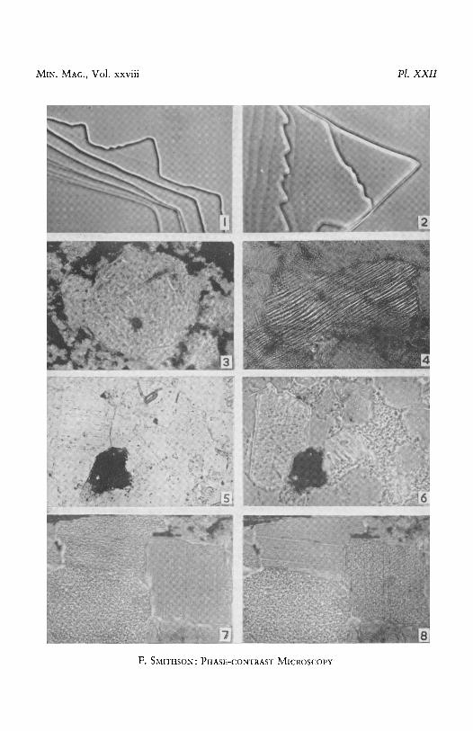
two contiguous materials of different refractive indices is well seen by examining the torn edges of very thin flakes of muscovite immersed in two media, one of lower and one of higher refractive index than that of the mineral (a 1"58, fl 1.59). In cedarwood oil (n 1-52) a small fringe of the field near the flake is brighter than the general field grey (pl. XXII , fig. 1). The edge of the flake is dark, and the dark belt fades gradually into grey. At each step from one cleavage surface to another there is also a bright belt at the foot and a dark band on the upper step. In a-bromonaphthalene (n 1"66) the effect is the reverse of the above. The belt surrounding the flake and at the foot of each step is clark; the edge of the flake and the edge of each step is bright (fig. 2).
Relief.--It is well known that the boldness of outline and apparent roughness of surface of a mineral mounted in Canada balsam give some
Bb
386 F. SMITHSON ON
indication of its refractive index. According to descriptions in students ' text-books, if the mean refractive index differs by less than about 0.1 from tha t of balsam the relief can generally be described as ' moderate ', while a difference of 0.2 gives 'high' or ' ve ry high' relief. With phase- contrast these appearances occur with very much lower refractive index differences. For example, sanidine and microcline with a difference from balsam of about 0.02 and leucite (fig. 3) with a difference of about 0-03, all show speckling which should probably be at tr ibuted to surface roughness; apati te (difference about 0.10) shows very pronounced speckling.
Evidence of the results of stress,--Evidence tha t a grain of quartz has been subjected, a t some t ime during its history, to great stresses is often given by strain shadows, seen when the section is rotated between crossed nicols. This type of deformation is not revealed by phase- contrast, but sections which show these strain shadows sometimes show a kind of banding which can be detected with ordinary illumination, as a series of rather feeble parallel Becke lines lying within the grain and moving as the microscope is racl~ed up and down. A section of such a grain viewed with phase-contrast and correctly focused shows a series of light and dark parallel lenticular bands (fig. 4).
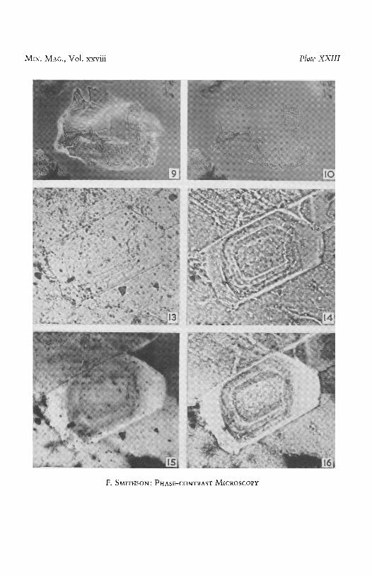
Heterogeneity.--Where there is heterogeneity of composition within a mineral resulting in slight differences of refractive index in adjacent parts, the phase-contrast microscope should reveal this feature in light and shade. Zoning of felspars, for example, may show itself as an alter- nation of light and dark bands (pl. X X I I I , figs. 13 and 14) ; and struc- tures in serpentine may be shown up with enhanced clearness. When the composition is homogeneous, but consists of minute particles of a mineral (e.g. in the kaolin in figs. 5 and 6), a speckled appearance may result, somewhat resembling tha t due to roughness of surface.
Phase-contrast plus single polarizer.
In the work to be described, polaroids or nicols were used on the instrument with a view to making it a combined polarizing and phase- contrast microscope. Such an instrument is not to be confused with phase-contrast microscopes in which polaroid is used in the construction of the equipment which produces and controls the phase difference. 1'2"a
1 Zeiss Catalogues. 2 E. W. Taylor, The control of amplitude in phase-contrast microscopy. Proc.
Roy. Soc. London, Set. A, 1947, vol. 190, pp. 422-426. a It. Osterberg, The polanret microscope. Journ. Opt. Soc. Amer., 1947, vol. 37,
pp. 726-730.
PtIASE-COI~TRAST MICROSCOPY 387
The writer (loc. cir., 1946) has pointed out that, in the examination of thin sections of rocks under the phase-contrast microscope, an im- provement of the image may result from polarizing the beam. I t is easy to see how this is possible. I f a birefringent mineral (1.55 and 1.53, mean 1.54) is in Canada balsam (n 1.54) no clear outline will be seen. With a polarizer suitably orientated, a refractive index difference as great as 0.01 may be produced and may be detected by means of phase-contrast. I f the refractive indices of the mineral are, say 1.59 and 1.53 (mean 1.56) the insertion of a polarizer may reduce the refractive index difference from 0.02 to 0-01 or increase it to 0.05. Hence, orientation of the polarizer is of importance, and in a rock section it is usually impos- sible to improve all parts of the field at the same time. Nevertheless, the changes which occur as the polarizer or the stage is rotated provide information about the optical properties of the minerals present.
'Twinkling'.--The ' twinkling' shown by many of the carbonate minerals mounted in Canada balsam when rotated 'relative to the vibration plane of polarized light is well known. In mounts of mineral grains it shows itself chiefly as a change in the boldness of outline; in sections the change of apparent roughness of surface is a conspicuous feature. The condition necessary for a mineral to show this phenomenon clearly with an ordinary polarizing microscope is that the mineral should possess one refractive index near to that of Canada balsam and another differing by at least 0.10. Using a single polarizer on the phase: contrast microscope the phenomenon is distinctly seen in minerals with much lower birefringence. For example, transverse sections of muscovite (refractive index for light vibrating normal to cleavage 1.55 ; parallel to cleavage 1.58 to 1-59) shows change of apparent roughness very con- spicuously (pl. XXII , figs. 7 and 8). Changes in boldness of outline have been observed with grains of scapolite (pl. XXI I I , figs. 9 and 10), cancrinite, oligoclase, and quartz. Grains of chalcedony (crushed carnelian) showed clear textural detail in one position, but lack of it after a rotation of 90 ~ ; grains of flint showed no such change. This difference of behaviour between the two minerals is to be attributed to a more or less parallel orientation of particles in the former case and a random orientation in the latter.
Inclusions and intergrowths.--The change in clearness of boundaries which results when a single polarizer is introduced is most noticeable with associations of birefr~ngent minerals whose mean refractive indices are almost identical. Thus, inclusions of one felspar in another may sometimes be made clearer by ,an appropriately oriented polarizer.
3 8 8 F. SMITHSON ON
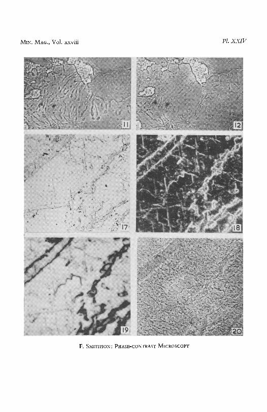
Examples of myrme]dte (intergrowth of quartz and plagioclase felspars) have been observed in which contrast between the two minerals can be varied by changing the orientation of the polarizer (pl. XXIV, figs. 11 and 12).
Phase-contrast plus polarizer and analyser. Perhaps the chief advantage of working with the combined polarizing
and phase-contrast microscope is the opportunity it affords of changing over from the phase-contrast to the crossed-nicol effect in order to carry out the established tests for the identification of minerals, and so to correlate the new information with the old. I t is, however, sometimes advantageous to observe the effect of phase-contrast plus crossed nicols or of phase-contrast plus parallel nicols, or of either of these combinations with the further addition of a gypsum or a mica plate. The uses of these methods have not been fully explored, but it has been noticed that they sometimes give clearer and sometimes less clear images than those obtained with crossed nicols alone.
Ph XXIII , figs. 15 and 16 show a case in which the zoning of a plagio- clase felspar was rendered much more distinct by using phase-contrast plus crossed nicols than with crossed uieols alone. The image obtained by using phase-contrast without crossed nicols (fig. 14) is perhaps the clearest of all, but the addition of crossed nicols enables the relationship of the zoned felspar to the surrounding grains to be more clearly seen.
Conclusion. I t should perhaps be emphasized that, in phase-contrast microscopy,
when two adjacent parts of the field containing the image of a perfectly transparent object differ in intensity, all that can be concluded from this fact is that there must be a small difference in optical path through the corresponding parts of the object. This difference in path may be due to :
(a) differences in thickness (e.g. roughness of surface of section), (b) difference in composition (e.g. two different minerals or varieties,
giving difference in refractive index), (c) difference in optical orientation (giving difference in refractive
index). This applies only when polarized light is used.
I t is not always easy to identify the actual causes. Contrast due to roughness of surface is enhanced by focusing on the surfaces of the section rather than on the detail lying between them, and such contrast can be made to disappear by immersion in a liquid of appropriate refractive index. Contrast due to roughness of surface may conceal other detail and such immersion may clarify detail due to other causes.
PHASE-CONTRAST MICROSCOPY 389
Opaque particles are less clearly seen by using phase-contrast than by using the ordinary methods of microscopy, as can be seen by comparing the following photomicrographs: fig. 5 with fig. 6; fig. 13 with fig. 14; fig. 15 with fig. 16.
Contrast methods not involving phase difference.
Most phase plates are treated with some opacifying substance in- tended to alter the ratio of intensities of the deviated and undeviated
:•..RIMARY IMAGE, ~-PRIMARY IMAGE, A~PRIMARY IMAGE, FORMED BY //I~ FORMED BY / \ FORMED BY INTERFERENCE OF I I D. DEVIATED RAYS / ~ UNDEVIATED
" "- UNDEVIATED RAYS / I l
�9 "
t / \ ~ PHASE / . ~ O B J E C T WE ~ l e e B ~ O ~ _ . E C T I V I E PLATE STOP
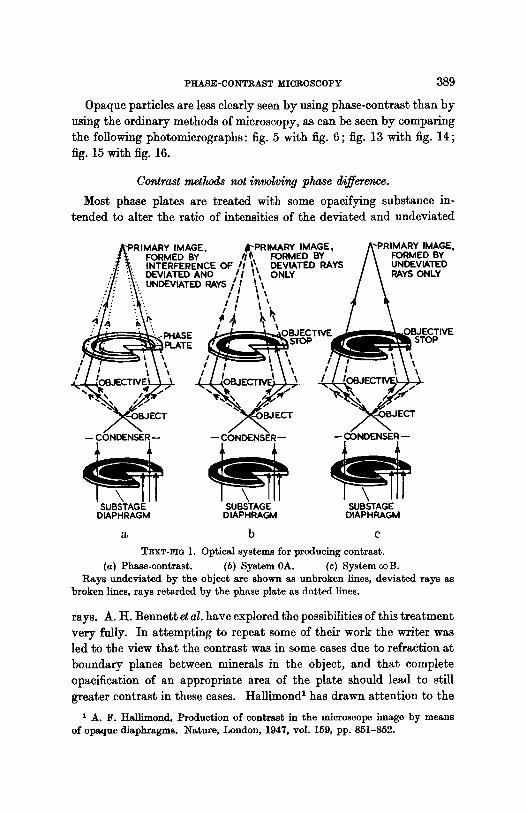
TEXT-FIe 1. Optical systems for producing contrast. (a) Phase-contrast. (b) System 0A. (c) System ooB.
Rays undeviated by the object are shown as unbroken lines, deviated rays as broken lines, rays retarded by the phase plate as dotted lines.
rays. A. H. Bennett et al. have explored the possibilities of this treatment very fully. In attempting to repeat some of their work the writer was led to the view that the contrast was in some cases clue to refraction at boundary planes between minerals in the object, and that complete opacification of an appropriate area of the plate should lead to still greater contrast in these cases. Halllmond 1 has drawn attention to the
t A. F. Hallimond, Production of contrast in the microscope image by means of opaque diaphragms. Nature, London, 1947, vol. 159, pp. 851-852.
390 F. SMITHSON O1~
fact tha t refraction phenomena have been neglected in phase-contrast theory and tha t contrast can be developed by means of stops alone. The objective annuli used by the writer appear to differ from those used by Hall imond in tha t they correspond exact ly in apparent form (as viewed, in position, through the auxil iary microscope) with the sub- stage diaphragm and are of two types as shown in text-fig. 1:1
0A Blackened annulus corresponding to the t ransparent annulus of the substage diaphragm.
~ B Transparent annulus corresponding to the t ransparent annulus of the substage diaphragm.
Images obtained with these methods and with positive phase contrast are shown in pl. XXIV, figs. 17-20. The conclusion to be drawn from them is not tha t one method is bet ter than another, but t ha t each emphasizes different features, as follows:
Ordinary i l lumination: Small opaques.
Type 0A: Microcline-plagioclase boundaries, cleavage, dust particles.
Type ooB: Microline-plagioclase boundaries.
Positive phase-contrast : Detail within the felspar areas (roughness of surface of section ?).
EXrLAI~ATm~ OF PLATES XXII-XXIV.
Phase-contrast photomicrographs. PLATE XXII. FIG. I. Muscovite flake in medium of lower refractive index. Phase-contrast.
• 150. Fro. 2. Muscovite flake in medium of higher refractive index. Phase-contrast.
• FIO. 3. Leucite, in leucitophyre, Naples. Focused on surface of section. Phase-
contrast. • 100. FIo. 4. Quartz in Ordovician grit, Co. Dublin, showing effects of pressure. Phase-
• 100. FIG. 6. Same field, showing intersticial kaolin. Phase-contrast. • 100. FIG. 7. Muscovite in Leinster granite. Phase.contrast. Single nicol, vibration
direction E.-W. • 50. Fro. 8. Same field. Vibration direction N.-S. • 50.
1 The symbols used are based on those used by A. H. Bennett e~ a/. (1946, loc. cit.). They use the letter A when the deviated light is partially suppressed and B when the nndeviated light is partially suppressed. Numbers preceding A and B represent the ratio intensity of deviated light/intensity of undeviated light.
PHASE-CONTRAST MICROSCOPY 391
I'LATE XXIII.
FIG. 9. Seapolite, Canada. Phase-contrast. Single nicol, vibration direction E.-W. • 60.
FIG. 10. Same field. Vibration direction N.-S. • 60.
PLaT~. XXIV.
Fro. 11. Myrmekite in Leinster granite. Phase-contrast. Single nicol, vibration direction E.-W. • 75.
Fxo. 12. Same field. Vibration direction N.-S. • 75.