1 THE APPLICATION OF RCC IN SOUTH AFRICA Johann Geringer INTRODUCTION The initial application of roller compacted concrete (RCC) in the USA (Willow Creek Dam, 1975) and Pakistan (Tarbela Dam repairs, 1974-1986), spurred engineers of the South African Department of Water Affairs and Forestry (DWAF) on to investigate the potential application of RCC for dams in South Africa. After some initial trials with RCC the first 3 RCC dams were constructed almost simultaneously. The Zaaihoek Dam and De Mistkraal Weir were designed and constructed by DWAF while the Arabie Dam, now called Flag Boshielo Dam, was designed by a consultant and constructed by a contractor for the then Leboa Homeland Government. The latter, a composite dam with a concrete spillway and an embankment left flank, was mainly designed in accordance with USA practices of the time. The design of the two DWAF dams was, however, based on DWAF research and design ideas. There were also other differences. The Zaaihoek and De Mistkraal dams were provided with stepped spillways while the Flag Boshielo Dam had a smooth spillway. The success achieved with the Zaaihoek and De Mistkraal dams paved the way for further RCC dams. These two dams were soon followed by the Wriggleswade and Glen Melville RCC gravity dams and the Knellpoort and Wolwedans RCC arch-gravity dams. Thereafter followed a number of other dams and today there are 27 dams in South Africa where RCC has been used in one way or another. Looking back it is perhaps proper to acknowledge that the Zaaihoek and Wolwedans are the two dams that contributed most to the development of the RCC technology in South Africa. It is, however, also true that each RCC dam built to date made a contribution in one way or another. It is the purpose of this paper to show how RCC design and construction techniques were developed with time and how RCC is today applied in a general way at South African dams. HISTORICAL DEVELOPMENT OF DWAF DESIGN STANDARDS FOR RCC DAMS The first trials with RCC occurred in 1978 at Kwena Dam (formerly known as Braam Raubenheimer Dam), near Lydenburg in the Limpopo Province. Initial testing was focused on establishing a workable RCC mix design and on selecting suitable plant for placing and compaction. Once confidence was gained with both the material and plant, RCC was placed in the right bank tongue wall of the composite dam comprising a central concrete spillway with embankment flanks. Hexagonal precast concrete panels were used to form the faces of this wall. It was, however, found that these panels created problems with RCC placing and that alternative and more efficient ways had to be found to form faces. The good results obtained at Kwena Dam provided the confidence to design and construct “all RCC” dams. RCC and bedding layer mix specifications The first two dams designed by DWAF as “all RCC” dams were the 47 m high Zaaihoek Dam and the 30 m high De Mistkraal Weir, both gravity dams. Both dams were considered experimental in
Transcript
1
THE APPLICATION OF RCC IN SOUTH AFRICA
Johann Geringer INTRODUCTION The initial application of roller compacted concrete (RCC) in the USA (Willow Creek Dam, 1975) and Pakistan (Tarbela Dam repairs, 1974-1986), spurred engineers of the South African Department of Water Affairs and Forestry (DWAF) on to investigate the potential application of RCC for dams in South Africa. After some initial trials with RCC the first 3 RCC dams were constructed almost simultaneously. The Zaaihoek Dam and De Mistkraal Weir were designed and constructed by DWAF while the Arabie Dam, now called Flag Boshielo Dam, was designed by a consultant and constructed by a contractor for the then Leboa Homeland Government. The latter, a composite dam with a concrete spillway and an embankment left flank, was mainly designed in accordance with USA practices of the time. The design of the two DWAF dams was, however, based on DWAF research and design ideas. There were also other differences. The Zaaihoek and De Mistkraal dams were provided with stepped spillways while the Flag Boshielo Dam had a smooth spillway. The success achieved with the Zaaihoek and De Mistkraal dams paved the way for further RCC dams. These two dams were soon followed by the Wriggleswade and Glen Melville RCC gravity dams and the Knellpoort and Wolwedans RCC arch-gravity dams. Thereafter followed a number of other dams and today there are 27 dams in South Africa where RCC has been used in one way or another. Looking back it is perhaps proper to acknowledge that the Zaaihoek and Wolwedans are the two dams that contributed most to the development of the RCC technology in South Africa. It is, however, also true that each RCC dam built to date made a contribution in one way or another. It is the purpose of this paper to show how RCC design and construction techniques were developed with time and how RCC is today applied in a general way at South African dams. HISTORICAL DEVELOPMENT OF DWAF DESIGN STANDARDS FOR RCC DAMS The first trials with RCC occurred in 1978 at Kwena Dam (formerly known as Braam Raubenheimer Dam), near Lydenburg in the Limpopo Province. Initial testing was focused on establishing a workable RCC mix design and on selecting suitable plant for placing and compaction. Once confidence was gained with both the material and plant, RCC was placed in the right bank tongue wall of the composite dam comprising a central concrete spillway with embankment flanks. Hexagonal precast concrete panels were used to form the faces of this wall. It was, however, found that these panels created problems with RCC placing and that alternative and more efficient ways had to be found to form faces. The good results obtained at Kwena Dam provided the confidence to design and construct “all RCC” dams. RCC and bedding layer mix specifications The first two dams designed by DWAF as “all RCC” dams were the 47 m high Zaaihoek Dam and the 30 m high De Mistkraal Weir, both gravity dams. Both dams were considered experimental in
2
the sense that it provided opportunities for further research into RCC in order to improve numerous technical aspects related to mix design and construction methods. The RCC mix designs of these two dams were partially based on USA practices but also incorporated new South African ideas. The RCC mixes contained 3 stone sizes, viz 9.5 -19 mm, 19 – 38 mm and 38 – 76 mm while the cementitious contents were limited to 116 kg/m3 (70% PFA: 30% OPC) at De Mistkraal and 120 kg/m3 (70% MGBS and 30% OPC) at Zaaihoek. Sands used in the mixes were blends of pit and crusher sands. The faces of these dams were formed with facing concrete placed against specially designed steel shutter that could easily be lifted and which did not interfere with either RCC placing or compaction. A 75 mm thick bedding layer was placed on cold joints to ensure good bonding whenever new RCC was placed on older RCC surfaces. The bedding layer comprised facing concrete with the 38 – 76 mm stone fraction removed. Though generally good results were obtained at these two dams, difficulties were sometimes experienced with the segregation of the RCC due to the large stone sizes present in the RCC mixes. This consequently led to abandonment of the practice to use stone sizes larger than 50 mm. Smaller maximum stone sizes are generally only used either for small structures or pavements while for large dams 50mm is used. Further lessons were learned at Zaaihoek Dam which greatly influenced the future design of South African RCC dams designed by DWAF. Crack control At Zaaihoek Dam the spillway section was constructed first and thereafter the non-overspill sections on either side of the spillway. In order to provide a good starting surface for the placing of RCC in the spillway section, mass concrete blocks, complete with formed transverse contraction joints at 15m intervals, were placed on the solid dolerite rock foundation. These blocks varied in thickness from about 1.5 to 2.5m in places and were also placed in a stepped manner on the slope towards the left bank. Once these foundation blocks attained sufficient strength, RCC was placed thereon. No crack inducers or water stops were provided at the upstream face of the RCC as it was believed, by many RCC experts in the world at the time, that because of its low cementitious content, RCC dams would not crack. However, before the dam was completed, cracks developed from the foundation upwards to the crest of the spillway. The origin of these cracks corresponded to the formed contraction joints of the mass concrete blocks below. It was very apparent to the designers that RCC can crack and that the use of jointed mass concrete blocks on the foundation can induce cracks in the RCC above. As a consequence of this experience the design philosophy of RCC dams was changed. Firstly, the use of mass concrete on the foundation was limited to dental treatment only and RCC was as far as possible placed directly on the foundation rock. Secondly, vertical crack inducers, complete with water stops, were provided at 10 m intervals in the upstream faces of the non-overspill sections of the dam. The results obtained from this design change proved highly satisfactory and became a design standard for subsequent dams. The spillway crest of Zaaihoek Dam was provided with a non-reinforced ogee shaped concrete cap placed on top of the RCC. The height of the cap was limited to 1.5 m in an effort to minimize the use of conventional concrete in the dam. The spillway cap was cast in 10 m long sections. Shortly after being cast, transverse cracks appeared at roughly third points of each of these blocks. It was thought that these cracks developed as a result of the rapid cooling of the crest caused by pressure and temperature drops as winds accelerated over the crest. Although these cracks were relatively small (1 to 2 mm wide) and of no structural consequence, there was the concern that they may become seating points for cracks developing downwards into the RCC. A decision was therefore made that in future spillway caps should be reinforced to limit intermediate cracking. This appears to have been a wise decision at the time as at subsequent dams it prevented intermediate cracks from developing downwards into the RCC below.
3
The potential of cracks developing downwards from the crest of a dam as a result of wind blowing over the crest is real and should always be kept in mind by the designer. It is therefore recommended that the designer is aware of the kind of weather conditions that can be encountered at a specific site. An example of a dam site where extreme changes in weather conditions have occurred during a single day is Wriggleswade Dam, near Stutterheim in the Eastern Province of South Africa. At the time when the RCC was already placed close to the crest of the spillway, a sudden drop in ambient temperature occurred. During the course of the morning, as in the days before, the ambient temperatures were relatively high reaching levels of about 30 to 320C by about noon. Within hours the situation changed as a cold front, accompanied by a strong wind, swept over the area. By about 14h00 the ambient temperature had dropped to about 15oC and was decreasing further as time went on. The wind blew exceptionally strong over the crest of the dam. The cold spell lasted for about two to three days whereafter the weather again became pleasant as before. Before the cold spell occurred, very few cracks could be detected at induced crack joints in the wall and where present the were limited to the bottom part of the wall. No cracks were visible near the crest of the wall. However, shortly after the cold spell, cracks were observed on all induced crack joints in the higher part of the dam. The widest cracks occurred at the crest and decreased in size further down the wall. The cracks at the crest of the dam were 2 to 3 times as wide as those observed at the bottom of the wall a few days before. Luckily, all the cracks that resulted from the temperature shock formed on induced joints and no intermediate cracks were observed. This is most likely due to the fact that no intermediate cracks were seated at the time. Galleries A second lesson learned at Zaaihoek Dam concerned the way in which drainage galleries are to be constructed. Influenced at the time by ideas and reports of overseas experts on simple ways to construct galleries in RCC dams, the gallery within the spillway section of Zaaihoek Dam was constructed with crushed stone. The stone was placed between timber planks, 2.5m apart along the gallery line, to a depth of 250mm which corresponded to the thickness of a compacted RCC layer. RCC was then placed on either side of the planks to a thickness of 300mm. The planks were then removed and the RCC compacted. Although the method offered the initial advantage of speeding up the gallery construction, it resulted in a very difficult, slow and expensive process of removing (mining out) the crushed stone at a later stage. Furthermore, it resulted in a very unsatisfactory surface finish of both the gallery roof and walls. Similar unsatisfactory results were obtained at Flag Boshielo Dam (formerly named Arabie Dam) where sand bags were used to form the gallery. The result of this experience prompted the designers to construct the remainder of the dam’s galleries in the non-overspill sections with proper formwork against which facing concrete was placed. The results obtained with properly formed galleries were very satisfactory and set the standard for the construction of future galleries where the walls were formed with formwork and the roof section with precast concrete arches. Using precast arches for forming the roof had two advantages. Firstly, it reduced the area of formwork required to form the vertical walls of the gallery. Secondly, the 150mm thick arches required less concrete per lineal metre of gallery than simply supported concrete planks placed across the gallery. The reason being that arches are structurally more efficient than simply supported beams. See Figure 1.
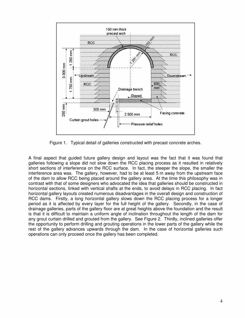
4
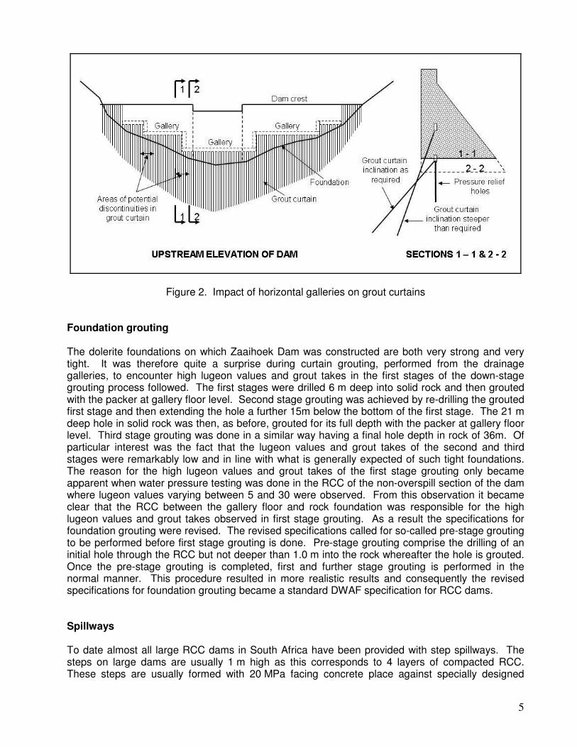
Figure 1. Typical detail of galleries constructed with precast concrete arches. A final aspect that guided future gallery design and layout was the fact that it was found that galleries following a slope did not slow down the RCC placing process as it resulted in relatively short sections of interference on the RCC surface. In fact, the steeper the slope, the smaller the interference area was. The gallery, however, had to be at least 5 m away from the upstream face of the dam to allow RCC being placed around the gallery area. At the time this philosophy was in contrast with that of some designers who advocated the idea that galleries should be constructed in horizontal sections, linked with vertical shafts at the ends, to avoid delays in RCC placing. In fact horizontal gallery layouts created numerous disadvantages in the overall design and construction of RCC dams. Firstly, a long horizontal gallery slows down the RCC placing process for a longer period as it is affected by every layer for the full height of the gallery. Secondly, in the case of drainage galleries, parts of the gallery floor are at great heights above the foundation and the result is that it is difficult to maintain a uniform angle of inclination throughout the length of the dam for any grout curtain drilled and grouted from the gallery. See Figure 2. Thirdly, inclined galleries offer the opportunity to perform drilling and grouting operations in the lower parts of the gallery while the rest of the gallery advances upwards through the dam. In the case of horizontal galleries such operations can only proceed once the gallery has been completed.
5
Figure 2. Impact of horizontal galleries on grout curtains Foundation grouting The dolerite foundations on which Zaaihoek Dam was constructed are both very strong and very tight. It was therefore quite a surprise during curtain grouting, performed from the drainage galleries, to encounter high lugeon values and grout takes in the first stages of the down-stage grouting process followed. The first stages were drilled 6 m deep into solid rock and then grouted with the packer at gallery floor level. Second stage grouting was achieved by re-drilling the grouted first stage and then extending the hole a further 15m below the bottom of the first stage. The 21 m deep hole in solid rock was then, as before, grouted for its full depth with the packer at gallery floor level. Third stage grouting was done in a similar way having a final hole depth in rock of 36m. Of particular interest was the fact that the lugeon values and grout takes of the second and third stages were remarkably low and in line with what is generally expected of such tight foundations. The reason for the high lugeon values and grout takes of the first stage grouting only became apparent when water pressure testing was done in the RCC of the non-overspill section of the dam where lugeon values varying between 5 and 30 were observed. From this observation it became clear that the RCC between the gallery floor and rock foundation was responsible for the high lugeon values and grout takes observed in first stage grouting. As a result the specifications for foundation grouting were revised. The revised specifications called for so-called pre-stage grouting to be performed before first stage grouting is done. Pre-stage grouting comprise the drilling of an initial hole through the RCC but not deeper than 1.0 m into the rock whereafter the hole is grouted. Once the pre-stage grouting is completed, first and further stage grouting is performed in the normal manner. This procedure resulted in more realistic results and consequently the revised specifications for foundation grouting became a standard DWAF specification for RCC dams. Spillways To date almost all large RCC dams in South Africa have been provided with step spillways. The steps on large dams are usually 1 m high as this corresponds to 4 layers of compacted RCC. These steps are usually formed with 20 MPa facing concrete place against specially designed
6
formwork. So far the step spillways have been performing exceptionally well. It is now proposed to construct future steps with grout enriched RCC. A number of model studies have been done on the stepped spillways of various dams in South Africa but the most useful work was that originally done for the De Mistkraal Weir. The model study for De Mistkraal did not only establish the energy dissipation that can be achieved with stepped spillways but also provided guidance for the economic design of spillway aprons. The study was also successful in recommending a new ogee profile for the spillway cap on the crest that was especially suitable for RCC construction as it minimized the height of the cap. The latter is normally constructed with conventional mass concrete and if the height can be limited construction can be expedited because smaller concrete volumes are involved. The ogee profile of De Mistkraal Weir became a design standard that has been used for many of South Africa’s RCC gravity dams like Wriggleswade, etc. Smaller steps have only found application on small weir structures and the heights of the steps usually correspond to the thicknesses of the RCC layers. These steps are usually constructed with RCC only. Smooth spillways have to date only found application at three RCC dams, viz Flag Boshielo Dam, Neusberg Weir and Inyaka Dam. As has been mentioned before, Flag Boshielo Dam was not designed by DWAF and the smooth spillway of the dam was purely a designers choice. The on average 5 m high Neusberg Weir is situated on the Orange River near Kakamas in the Northwest Province of South Africa. The weir has a downstream slope of 1:1 (H:V) and it was therefore decided to construct the weir with a smooth spillway. An additional objective was also to get experience with smooth surface construction for sloped faces in order to use RCC as cut-off walls where the embankment sections of composite dams join up with RCC spillway sections. The experience gained at Neusberg Weir was of great benefit for the construction of the Qedusizi Dam. River diversion River flow in South Africa is generally very seasonal with high flows occurring in the wet season and low flows during the dry season. Most of the country falls in the summer rainfall region and it is only the southwestern coastal strip that falls within the winter rainfall region. Advantage is usually taken of the low flow season to establish river diversion for the construction of RCC dams. Preparation for river diversion usually commences at the end of the wet season in order to start with construction activities at the beginning of the dry season. Considerable effort is made during this period to place as much concrete as possible in the river section of the dam with the aim of getting the wall at least above the top of the river diversion culvert. Once the wall has risen to this height, RCC can be placed uninterruptedly across the river at a rising rate of about a 1 m per day. On large and fair size rivers, river diversion is established through the provision of a culvert structure in the lowest part of the river. The culvert is constructed with mass concrete of which the width corresponds to the spacing of the dam’s transverse contraction/crack joints. See Figure 3. If the river flows are relatively high, more than one culvert may be necessary. Usually a very low earth embankment coffer dam, barely the height of the culvert structure, is constructed around the works to isolate it from the river. Once the diversion culvert is completed, equally low upstream and downstream coffer dams are built on either side of the culvert to isolate these areas for foundation excavation and concrete placing. During this phase the river is diverted through the culvert.
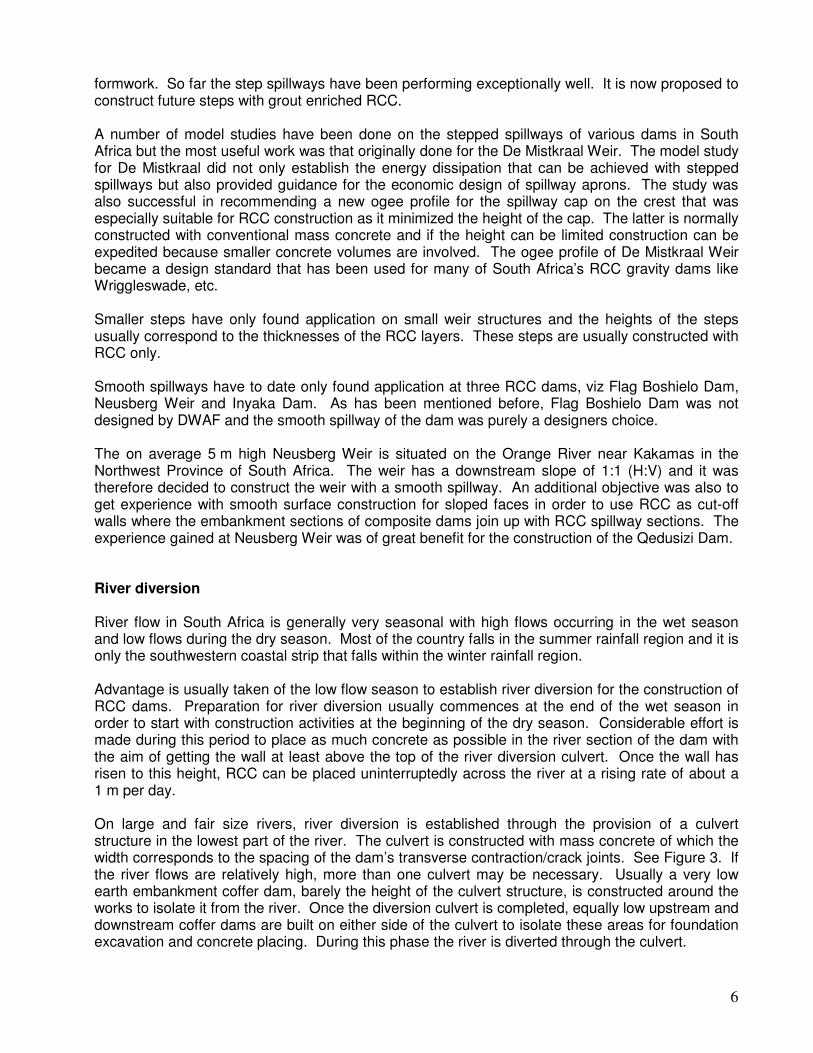
7
In the case of smaller streams and dams a less elaborate culvert can be provided by simply providing a pipe culvert, encased with facing concrete, within the RCC. There are various ways that this can be achieved but the aim is always to minimize the use of conventional concrete and to maximize the use of RCC.
Figure 3. Typical detail of river diversion culverts in dam walls. The philosophy adopted with river diversion is that the greatest risk occurs at the time when the dam foundations are exposed. Cleaning of flooded foundation excavations can cause considerable delays that may have serious financial and program consequences for the project. However, once the foundations are covered with concrete, the risk of flood damage decreases as there is usually very little damage when a RCC dam is overtopped by a flood. The greatest damages that can be incurred are usually associated with plant and other equipment washed off the wall. However, if a good flood warning system is in place, such plant can timeously be removed from the wall. In sizing the culvert, consideration is given to more than one flow condition. The first criteria is that the culvert must have the capability to discharge the river flows of the dry season. The second criteria is the discharge capacity that the culvert should have when the dam has achieved certain critical heights. The latter usually depends on other critical activities occurring at certain heights. As the discharge capacity of the culvert increases with increasing head, i.e. pool depth, both of these criteria can usually be met with the same culvert size. River diversion closure is nowadays achieved by pumping self-compacting flow-concrete into the culvert from the downstream side. This was first done at Wolwedans Dam. If the culvert is provided with an upward sloping roof in the downstream direction good contact is obtained between the culvert roof and flow-concrete. Although facilities for cavity grouting is usually provided along the walls and roof of the culvert, experience with post construction grouting has indicated that very tight contacts have been achieved as negligible grout takes have been observed.
8
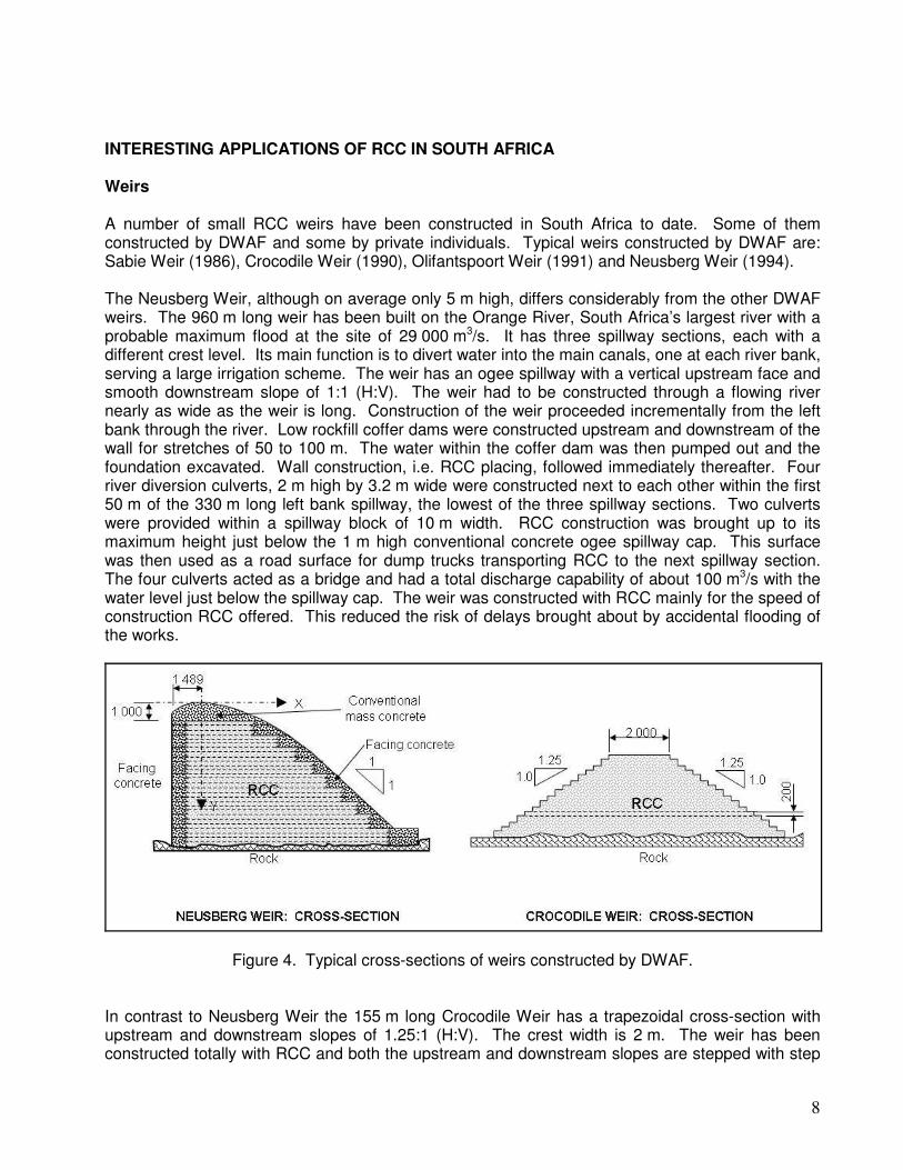
INTERESTING APPLICATIONS OF RCC IN SOUTH AFRICA Weirs A number of small RCC weirs have been constructed in South Africa to date. Some of them constructed by DWAF and some by private individuals. Typical weirs constructed by DWAF are: Sabie Weir (1986), Crocodile Weir (1990), Olifantspoort Weir (1991) and Neusberg Weir (1994). The Neusberg Weir, although on average only 5 m high, differs considerably from the other DWAF weirs. The 960 m long weir has been built on the Orange River, South Africa’s largest river with a probable maximum flood at the site of 29 000 m3/s. It has three spillway sections, each with a different crest level. Its main function is to divert water into the main canals, one at each river bank, serving a large irrigation scheme. The weir has an ogee spillway with a vertical upstream face and smooth downstream slope of 1:1 (H:V). The weir had to be constructed through a flowing river nearly as wide as the weir is long. Construction of the weir proceeded incrementally from the left bank through the river. Low rockfill coffer dams were constructed upstream and downstream of the wall for stretches of 50 to 100 m. The water within the coffer dam was then pumped out and the foundation excavated. Wall construction, i.e. RCC placing, followed immediately thereafter. Four river diversion culverts, 2 m high by 3.2 m wide were constructed next to each other within the first 50 m of the 330 m long left bank spillway, the lowest of the three spillway sections. Two culverts were provided within a spillway block of 10 m width. RCC construction was brought up to its maximum height just below the 1 m high conventional concrete ogee spillway cap. This surface was then used as a road surface for dump trucks transporting RCC to the next spillway section. The four culverts acted as a bridge and had a total discharge capability of about 100 m3/s with the water level just below the spillway cap. The weir was constructed with RCC mainly for the speed of construction RCC offered. This reduced the risk of delays brought about by accidental flooding of the works.
Figure 4. Typical cross-sections of weirs constructed by DWAF. In contrast to Neusberg Weir the 155 m long Crocodile Weir has a trapezoidal cross-section with upstream and downstream slopes of 1.25:1 (H:V). The crest width is 2 m. The weir has been constructed totally with RCC and both the upstream and downstream slopes are stepped with step
9
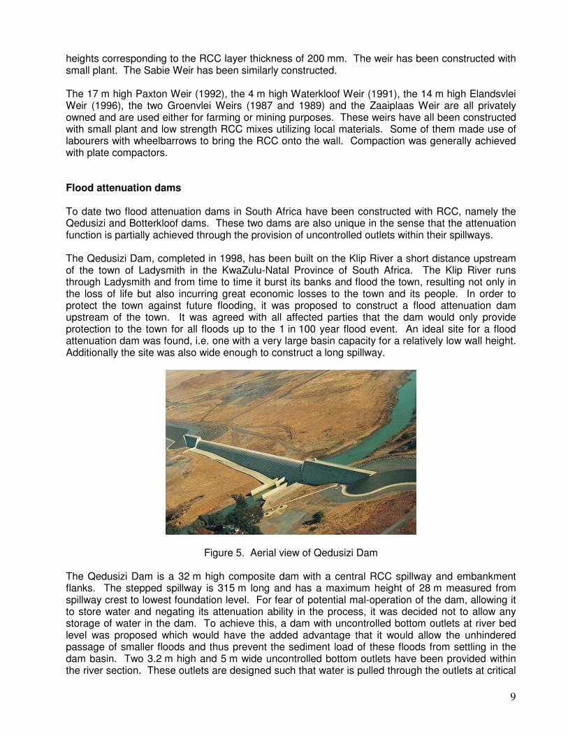
heights corresponding to the RCC layer thickness of 200 mm. The weir has been constructed with small plant. The Sabie Weir has been similarly constructed. The 17 m high Paxton Weir (1992), the 4 m high Waterkloof Weir (1991), the 14 m high Elandsvlei Weir (1996), the two Groenvlei Weirs (1987 and 1989) and the Zaaiplaas Weir are all privately owned and are used either for farming or mining purposes. These weirs have all been constructed with small plant and low strength RCC mixes utilizing local materials. Some of them made use of labourers with wheelbarrows to bring the RCC onto the wall. Compaction was generally achieved with plate compactors. Flood attenuation dams To date two flood attenuation dams in South Africa have been constructed with RCC, namely the Qedusizi and Botterkloof dams. These two dams are also unique in the sense that the attenuation function is partially achieved through the provision of uncontrolled outlets within their spillways. The Qedusizi Dam, completed in 1998, has been built on the Klip River a short distance upstream of the town of Ladysmith in the KwaZulu-Natal Province of South Africa. The Klip River runs through Ladysmith and from time to time it burst its banks and flood the town, resulting not only in the loss of life but also incurring great economic losses to the town and its people. In order to protect the town against future flooding, it was proposed to construct a flood attenuation dam upstream of the town. It was agreed with all affected parties that the dam would only provide protection to the town for all floods up to the 1 in 100 year flood event. An ideal site for a flood attenuation dam was found, i.e. one with a very large basin capacity for a relatively low wall height. Additionally the site was also wide enough to construct a long spillway.
Figure 5. Aerial view of Qedusizi Dam The Qedusizi Dam is a 32 m high composite dam with a central RCC spillway and embankment flanks. The stepped spillway is 315 m long and has a maximum height of 28 m measured from spillway crest to lowest foundation level. For fear of potential mal-operation of the dam, allowing it to store water and negating its attenuation ability in the process, it was decided not to allow any storage of water in the dam. To achieve this, a dam with uncontrolled bottom outlets at river bed level was proposed which would have the added advantage that it would allow the unhindered passage of smaller floods and thus prevent the sediment load of these floods from settling in the dam basin. Two 3.2 m high and 5 m wide uncontrolled bottom outlets have been provided within the river section. These outlets are designed such that water is pulled through the outlets at critical
10
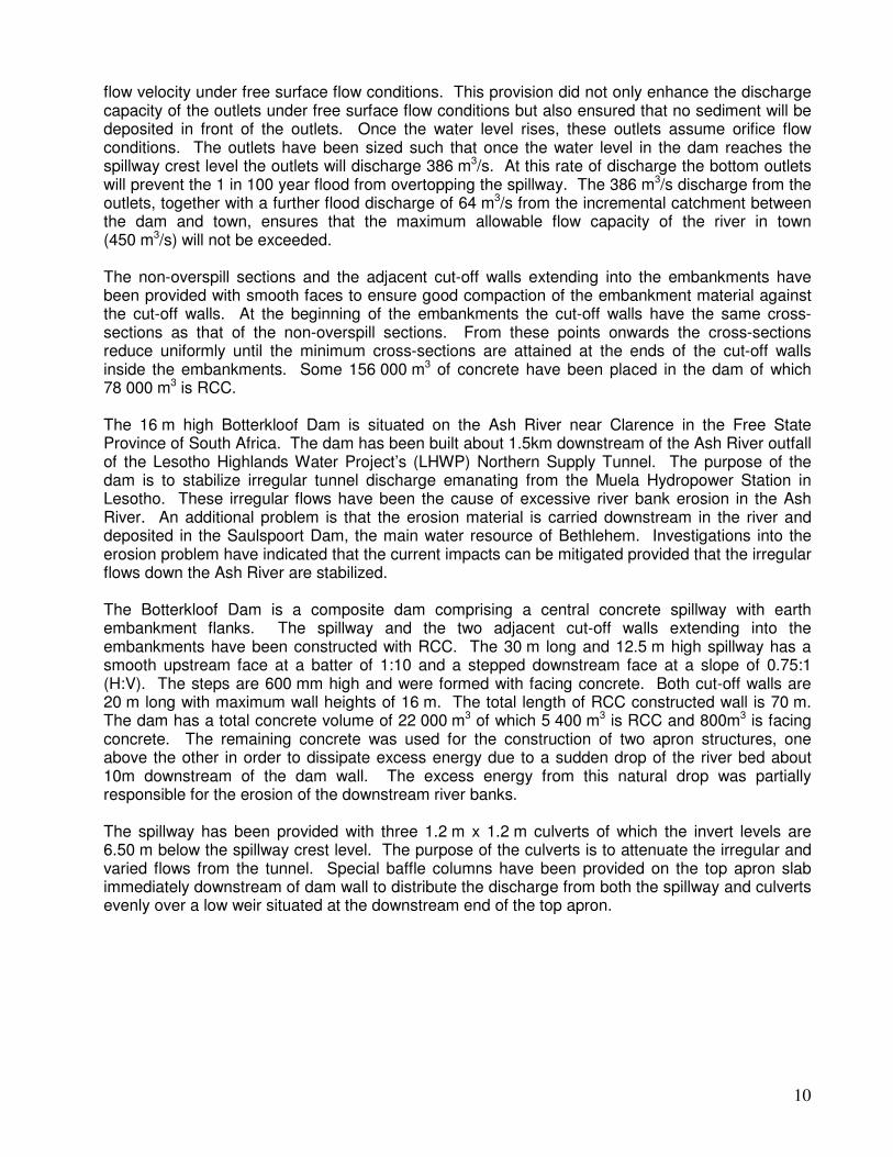
flow velocity under free surface flow conditions. This provision did not only enhance the discharge capacity of the outlets under free surface flow conditions but also ensured that no sediment will be deposited in front of the outlets. Once the water level rises, these outlets assume orifice flow conditions. The outlets have been sized such that once the water level in the dam reaches the spillway crest level the outlets will discharge 386 m3/s. At this rate of discharge the bottom outlets will prevent the 1 in 100 year flood from overtopping the spillway. The 386 m3/s discharge from the outlets, together with a further flood discharge of 64 m3/s from the incremental catchment between the dam and town, ensures that the maximum allowable flow capacity of the river in town (450 m3/s) will not be exceeded. The non-overspill sections and the adjacent cut-off walls extending into the embankments have been provided with smooth faces to ensure good compaction of the embankment material against the cut-off walls. At the beginning of the embankments the cut-off walls have the same cross-sections as that of the non-overspill sections. From these points onwards the cross-sections reduce uniformly until the minimum cross-sections are attained at the ends of the cut-off walls inside the embankments. Some 156 000 m3 of concrete have been placed in the dam of which 78 000 m3 is RCC. The 16 m high Botterkloof Dam is situated on the Ash River near Clarence in the Free State Province of South Africa. The dam has been built about 1.5km downstream of the Ash River outfall of the Lesotho Highlands Water Project’s (LHWP) Northern Supply Tunnel. The purpose of the dam is to stabilize irregular tunnel discharge emanating from the Muela Hydropower Station in Lesotho. These irregular flows have been the cause of excessive river bank erosion in the Ash River. An additional problem is that the erosion material is carried downstream in the river and deposited in the Saulspoort Dam, the main water resource of Bethlehem. Investigations into the erosion problem have indicated that the current impacts can be mitigated provided that the irregular flows down the Ash River are stabilized. The Botterkloof Dam is a composite dam comprising a central concrete spillway with earth embankment flanks. The spillway and the two adjacent cut-off walls extending into the embankments have been constructed with RCC. The 30 m long and 12.5 m high spillway has a smooth upstream face at a batter of 1:10 and a stepped downstream face at a slope of 0.75:1 (H:V). The steps are 600 mm high and were formed with facing concrete. Both cut-off walls are 20 m long with maximum wall heights of 16 m. The total length of RCC constructed wall is 70 m. The dam has a total concrete volume of 22 000 m3 of which 5 400 m3 is RCC and 800m3 is facing concrete. The remaining concrete was used for the construction of two apron structures, one above the other in order to dissipate excess energy due to a sudden drop of the river bed about 10m downstream of the dam wall. The excess energy from this natural drop was partially responsible for the erosion of the downstream river banks. The spillway has been provided with three 1.2 m x 1.2 m culverts of which the invert levels are 6.50 m below the spillway crest level. The purpose of the culverts is to attenuate the irregular and varied flows from the tunnel. Special baffle columns have been provided on the top apron slab immediately downstream of dam wall to distribute the discharge from both the spillway and culverts evenly over a low weir situated at the downstream end of the top apron.
11
Figure 6. View of the Botterkloof Dam Trough spillways for embankment dams The Inyaka Dam is the first composite dam in South Africa that has been provided with a massive central trough spillway of which a great part is constructed with RCC. The dam has been built on the Marite River, a tributary of the Sabie River, near Bushbuck Ridge in the Mpumalanga Province of South Africa. Its purpose is to provide domestic water to a rural and semi-rural population of about 650 000 people, irrigation water to a small area and to improve the environmental flows of the Sabie River. Inyaka Dam has a maximum height of 53 m and an overall length of 600 m of which 48.5 m is the width of the trough spillway at full supply level. The dam has been constructed in a very varying geology comprising granite gneiss with four diabase dykes crossing the site. The valley flanks consist mainly of residual granite soil, interspersed by completely weather diabase dykes. The position of the spillway was dictated by the fact that rock for the overspill structure was only available at a shallow depth in the river section. The trough spillway comprises a 58 m long horseshoe shaped overspill section at the upstream end followed by a 141.1 m long sloping spillway chute that ends in a 64 m long stilling basin at the downstream end. The total length of the trough spillway is 263.1 m. The height of the structure at the upstream end is about 58 m and the maximum height at the crest of the adjacent embankments is about 63 m. The smooth exterior faces of the chute have batters varying between 1:9 and 1:12. The crests of the chute walls slope in the downstream direction at 2.5:1 (H:V) until it joins the horizontal crests of the stilling basin side walls. The overall length of the horseshoe shaped overspill section is 138 m and the upstream semi-circular section has an extrados of 23.265 m. The overspill section has a freeboard of 4.6 m which is associated with a spillway discharge of 2 850 m3/s. A 1.0 m high parapet wall placed on the crests of both the chute and the embankment flanks increases the discharge capacity of the spillway to 3 500 m3/s which is only 300 m3/s less than the probable maximum flood of 3 800 m3/s. The ogee shaped overspill section has been provided with splitters of which the top surface is 4.4 m below the crest of the spillway. The ogee profile ends on a continuous 3 m wide horizontal ledge that has been provided 6 m below the ogee crest. The splitters and ledge together forms a
12
mechanism to dissipate some of the kinetic energy of water flowing over the spillway. Firstly it causes an enormous amount of aeration as water is deflected away from the spillway and secondly the aeration reduces the force of impact on the chute floor below. The huge amount of aeration also protects the chute floor against cavitation damage associated with high flow velocities.
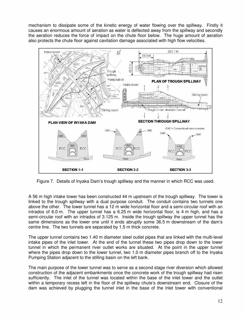
Figure 7. Details of Inyaka Dam’s trough spillway and the manner in which RCC was used. A 56 m high intake tower has been constructed 44 m upstream of the trough spillway. The tower is linked to the trough spillway with a dual purpose conduit. The conduit contains two tunnels one above the other. The lower tunnel has a 12 m wide horizontal floor and a semi-circular roof with an intrados of 6.0 m. The upper tunnel has a 6.25 m wide horizontal floor, is 4 m high, and has a semi-circular roof with an intrados of 3.125 m. Inside the trough spillway the upper tunnel has the same dimensions as the lower one until it ends abruptly some 36.5 m downstream of the dam’s centre line. The two tunnels are separated by 1.5 m thick concrete. The upper tunnel contains two 1.40 m diameter steel outlet pipes that are linked with the multi-level intake pipes of the inlet tower. At the end of the tunnel these two pipes drop down to the lower tunnel in which the permanent river outlet works are situated. At the point in the upper tunnel where the pipes drop down to the lower tunnel, two 1.0 m diameter pipes branch off to the Inyaka Pumping Station adjacent to the stilling basin on the left bank. The main purpose of the lower tunnel was to serve as a second stage river diversion which allowed construction of the adjacent embankments once the concrete work of the trough spillway had risen sufficiently. The inlet of the tunnel was located within the base of the inlet tower and the outlet within a temporary recess left in the floor of the spillway chute’s downstream end. Closure of the dam was achieved by plugging the tunnel inlet in the base of the inlet tower with conventional
13
concrete. After closure of the dam the recess left at the downstream end of chute spillway was backfilled with mass concrete and the permanent river outlet works formed therein. The tunnel was left open between these two points. The lower tunnel was designed for a maximum discharge of 650 m3/s and became functional in October 1998. In February 2000 a flood of 500 m3/s was safely diverted through it. The trough spillway was constructed as far as possible with RCC and the use of conventional mass concrete was limited to those areas where the placing of RCC was restricted either by limited space or specific construction details. Typical areas constructed with conventional mass concrete were for instance the areas immediately adjacent and above the conduits, a portion of the curved overspill section at the upstream end of the trough spillway, the ogee spillway sections containing the splitters and the upper parts (crests) of the side walls. Figure 7 illustrates in some way how RCC and conventional mass concrete were used in the trough spillway. In contrast to most other dam projects, the benefit of using RCC at Inyaka Dam did not lie in rapid construction and the savings it offered. In fact the placing rate at Inyaka Dam was very slow, varying from 60 m3/hr in open areas to only 20 m3/hr in congested areas. The main advantage, however, lay in the fact that the use of RCC eliminated the need to construct a considerable number of major transverse joints that would have required very expensive formwork. Compared with formed joints, crack joints induced in RCC are much more economical and therefore offered considerable savings. The RCC used at Inyaka Dam comprised the following mix proportions: 90 kg/m3 of water (W/C-ratio 0.50), 60 kg/m3 OPC, 120 kg/m3 PFA, 774 kg/m3 of sand, 385 kg/m3 of 4.75 – 19 mm stone, 569 kg/m3 of 19 – 38 mm stone and 480 kg/m3 of 38 – 53 mm stone Although the mix was required to attain a compressive strength of 15 MPa at 28-days, actual strengths obtained from 90-day cores were in the order of 35 MPa. One-year core strengths were on average about 40 MPa. Densities typically varied between 2 401 and 2 408 kg/m3. The bedding material specified for the RCC was a mortar which had to be applied in a thickness of 20 mm. The thickness was subsequently reduced to 10 mm when it was found that the 20 mm thick layer of mortar, when still wet, gave rise to pumping and rolling of the RCC layer above when any load was imposed on the RCC layer. In many cases the wheels of trucks made deep ruts into the RCC surface. Cores drilled of the RCC with 10 mm bedding layers indicated both good bonding of the layers and the absence of any hoeneycombing. The total volume of concrete used at Inyaka Dam amounted to 408 300 m3 of which 183 600 m3 was RCC. The total volume of material that went into the construction of the embankments is 1 173 000 m3. Arch gravity dams The idea of utilizing RCC for the construction of arch dams was already conceived by engineers of DWAF in 1986 during the construction of the De Mistkraal Weir and the Zaaihoek Dam. The opportunity soon arose in 1987 when dams were proposed in the gorges of the Rietspruit and the Great Brak River. Both sites lend themselves to the construction of arch/gravity dams and under the inspired leadership of the late Frank Hollingworth the design of the first RCC arch/gravity dams got started.
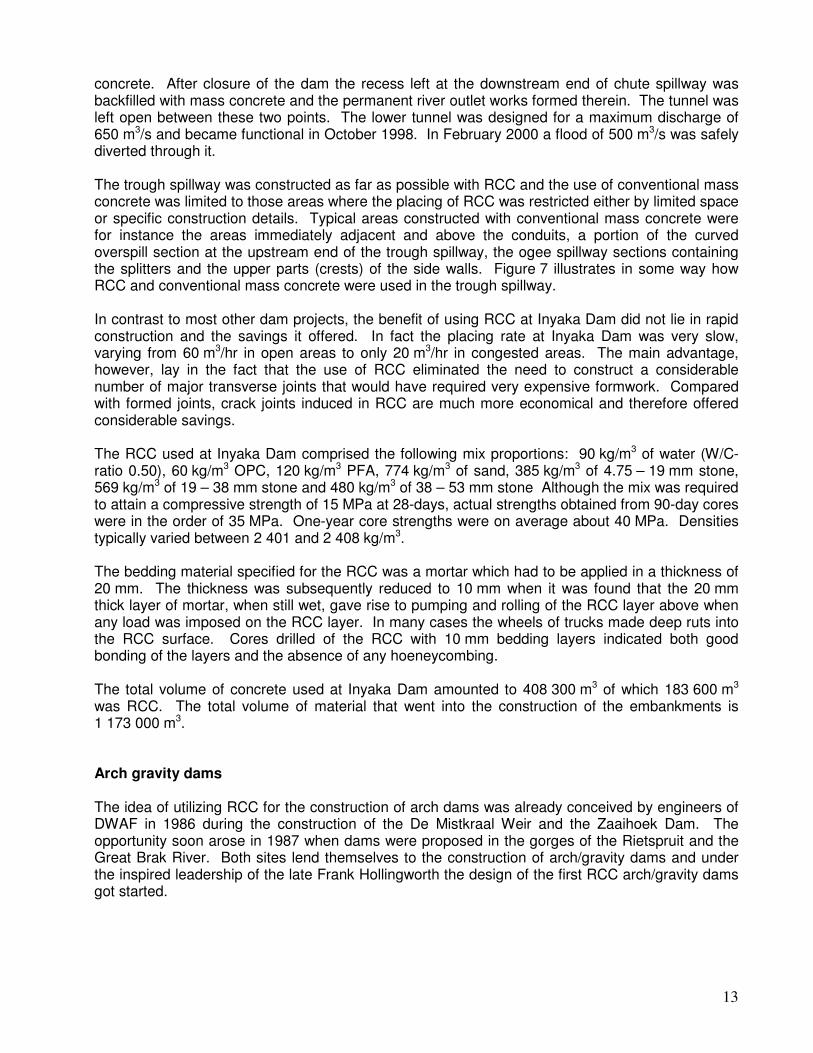
14
Figure 8. Knellpoort Dam (left) and Wolwedans Dam (right). The Knellpoort Dam is situated on the Rietspruit, a tributary of the Caledon River, near the town of Wepener in the Eastern Free State, close to the Lesotho border. This is traditionally an area that experiences very cold winters when temperatures can sometimes go as low as –5 to –10 oC. The dam serves as an off-channel storage dam for water pumped from the Caledon River. The storage is used to supply the city of Bloemfontein, the provincial capital, with urban and industrial water. The 50 m high dam is an asymmetric arch with an extrados of 80 m. The dam has a vertical upstream face and a stepped downstream face with a slope of 0.60:1 (H:V). The right flank of the arch abuts into a cliff on the right bank of the gorge while the left flank abuts into a straight gravity wall on the left flank. The dam has a crest length of 200m and contains a total volume of concrete of 59 000 m3 of which 45 000 m3 is RCC. The crest of the non-overspill section is 5 m wide to accommodate RCC placing. The outlet works comprise a free standing dry well inlet tower constructed against the upstream face of the wall. The RCC mix used for the dam comprised 102 kg/m3 of water, 61 kg/m3 of OPC, 142 kg/m3 of PFA, 697 kg/m3 of sand, 453 kg/m3 of 4.75- 19 mm stone and 1 310 kg/m3 of 19 – 50 mm stone. The coarse aggregate was crushed dolerite. An average 28-day cube strength of 17.2 MPa has been obtained with this mix. The Wolwedans Dam is situated on the Great Brak River near George in the Southern Cape Province. The dam is about 5 km from the coast. The climate of the area is generally very mild but can from time to time experience exceptionally hot days during summer when ambient temperatures can soar up to 38oC. These hot spells are caused by berg wind conditions that can last as long as 3 to 4 days. The purpose of the dam is to supply industrial water to the Mossgas gas-fuel plant as well as urban domestic water to the town of Mossel Bay. The 70 m high near symmetrical constant cross-section arch has an extrados of 135 m. Like Knellpoort Dam, it has a vertical upstream face and a stepped downstream face at a slope of 0.50:1 (H:V). The non-overspill sections have a crest width of 5 m. The total crest length of the dam is 270 m. The outlet works comprise a dry well intake tower on the upstream side that is structurally integrated with the dam wall. The dam has a total concrete volume of 203 000 m3 of which 127 000 m3 is RCC. The RCC mix used for the dam comprised 83 kg/m3 of water, 58 kg/m3 of OPC, 136 kg/m3 of PFA, 679 kg/m3 of sand, 430 kg/m3 of 4.75 – 19 mm stone, 625 kg/m3 of 19 – 38 mm stone and 469 kg/m3 of 38 – 53 mm stone. The coarse aggregate comprised quartzite cobbles sourced from Enon conglomerates. Although the average 28-day cube strengths of the RCC was only 16.1 MPa, 1 to 2 year core strengths varied between 19.1 to 53.8 MPa with an average of 32.7 MPa. Both dams were structurally analyzed with in-house developed finite element programs. The analyses indicated that relatively low stresses developed under the designs loads imposed on the
15
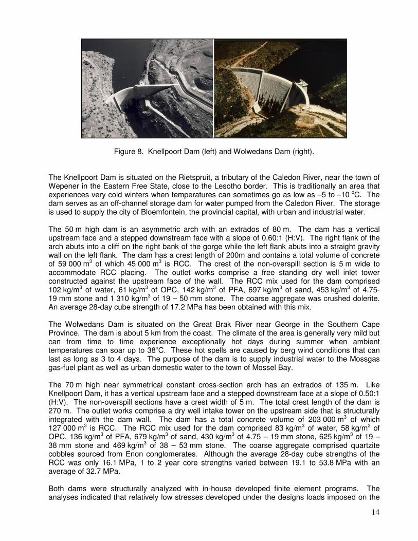
dams. The only concern was how the integrity of the arches would be maintained if cracks would develop as a result of the development of tensile stresses associated with temperature drops. The latter was of specific concern as it could easily happen that the construction could continue during hot spells. A practical solution was found to deal with this potential problem. Transverse crack joints would be induced at 10 m intervals along the length of the dam which at a later stage could be grouted. Various joint details were investigated on RCC test sections to select the best system. All that remained once the joint details were established was to find a way to determine when crack joint grouting would be necessary. This was resolved by providing crack meters at various positions and levels in the dam over crack joints. Figure 9 indicates how crack joint meters were provided at Wolwedans Dam.
Figure 9. Location of crack joint meters in Wolwedans Dam. RCC placing at Knellpoort Dam took place in 1988 during one of the coldest winters of the time and consequently the cracks that developed at the dam were never wide enough to warrant grouting of the joints. As a result none of the dam’s joints have ever been grouted. At Wolwedans delays were experienced during the winter months and RCC placing pressed on into the warmer months until it became so hot that instructions were given that all RCC placing had to stop. Furthermore, the liquid nitrogen used to cool down the RCC at the mixing plant had very little effect due to the small water requirement of the RCC mix. As a consequence fair size cracks developed on crack joints later on and it became necessary to grout the dam’s joints. Both dams are still behaving very well and to date there has not been any concern about the structural safety of the dams.
16
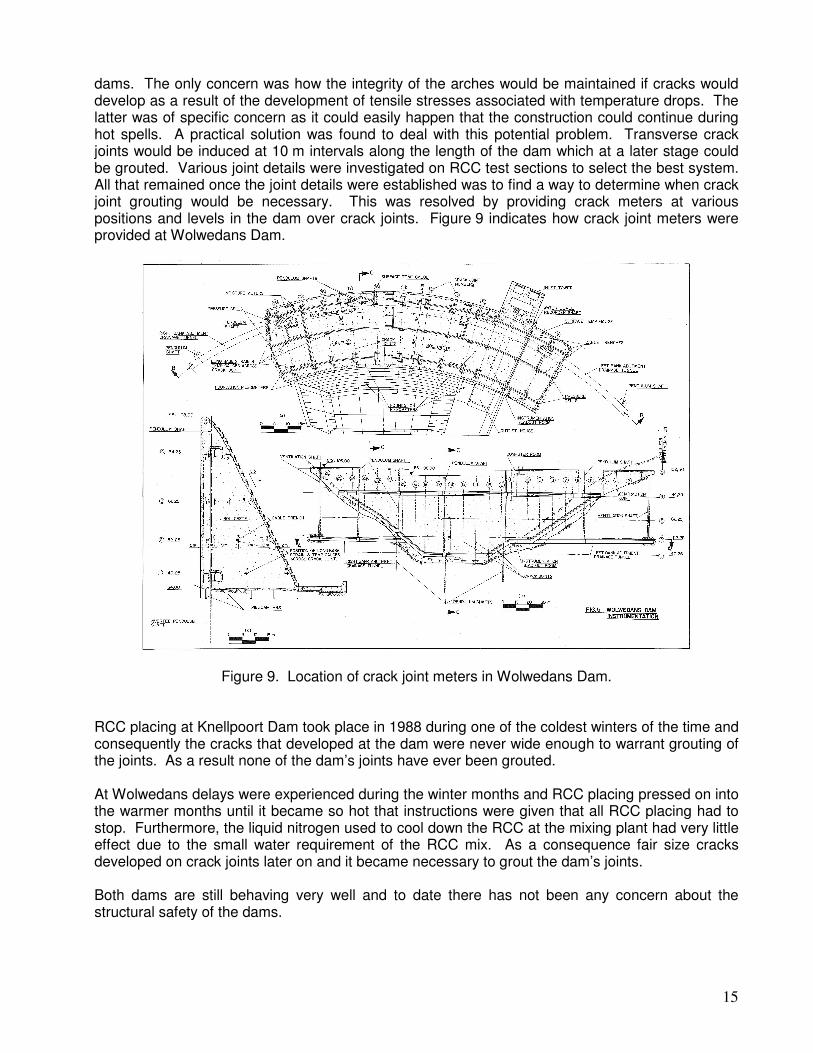
Placing RCC along slopes Construction on the 34 m high Wriggleswade Dam started in 1987. The dam is a straight “all-RCC” gravity dam with a total crest length of 757 m. The dam has been founded on siltstone. The siltstone has a high tendency to flake when exposed to the atmosphere. As a result specifications called for the quick covering of the siltstone surface after excavation. The easiest and quickest way to cover the freshly excavated foundation was to place RCC thereon. Not to loose time, the RCC was not placed horizontally but on slope. In this manner a RCC layer of a few metres thick could quickly be placed on the foundation and bring the concrete of the dam wall to a level above natural ground level. As the compaction attained for the RCC was within specifications, the contractor was allowed to complete the rest of the wall in this manner. This resulted in the rest of the wall being constructed in a series of humps of which the slopes were sometimes as steep as 5:1 (H:V). Figure 10 is an actual record of RCC placing in a third of the dam wall.
Figure 10. Part of the record of how RCC was placed in sloped fashion at Wriggleswade Dam.
The main benefits derived from using this method of RCC placing are:
• It allowed optimum utilisation of available plant capacity and man power;
• It reduced the area of a freshly placed RCC layer and therefore minimized the exposure time before being covered by the next layer - i.e. the risk of the RCC surface drying out is minimized;
• Access to other parts on the wall is very easy;
• It eliminated the need to construct expensive conventional transverse contraction joints that would be needed at the ends of placement sections that would be required to suite horizontal construction, and
• An overall financial benefit from all the savings accrued. Despite the unconventional way in which the RCC of Wriggleswade Dam has been placed, the dam is still behaving very well.
17
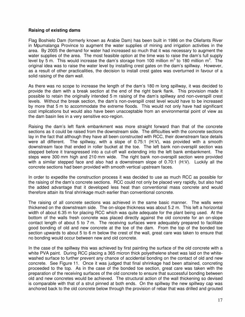
Raising of existing dams Flag Boshielo Dam (formerly known as Arabie Dam) has been built in 1986 on the Oliefants River in Mpumalanga Province to augment the water supplies of mining and irrigation activities in the area. By 2005 the demand for water had increased so much that it was necessary to augment the water supplies of the area. The most feasible option at the time was to raise the dam’s full supply level by 5 m. This would increase the dam’s storage from 100 million m3 to 180 million m3. The original idea was to raise the water level by installing crest gates on the dam’s spillway. However, as a result of other practicalities, the decision to install crest gates was overturned in favour of a solid raising of the dam wall. As there was no scope to increase the length of the dam’s 180 m long spillway, it was decided to provide the dam with a break section at the end of the right bank flank. This provision made it possible to retain the originally intended 5 m raising of the dam’s spillway and non-overspill crest levels. Without the break section, the dam’s non-overspill crest level would have to be increased by more that 5 m to accommodate the extreme floods. This would not only have had significant cost implications but would also have been unacceptable from an environmental point of view as the dam basin lies in a very sensitive eco-region. Raising the dam’s left flank embankment was more straight forward than that of the concrete sections as it could be raised from the downstream side. The difficulties with the concrete sections lay in the fact that although they have all been constructed with RCC, their downstream face details were all different. The spillway, with a slope of 0.75:1 (H:V), was provided with a smooth downstream face that ended in roller bucket at the toe. The left bank non-oversplil section was stepped before it transgressed into a cut-off wall extending into the left bank embankment. The steps were 300 mm high and 210 mm wide. The right bank non-overspill section were provided with a similar stepped face and also had a downstream slope of 0.70:1 (H:V). Luckily all the concrete sections had been provided with smooth vertical upstream faces. In order to expedite the construction process it was decided to use as much RCC as possible for the raising of the dam’s concrete sections. RCC could not only be placed very rapidly, but also had the added advantage that it developed less heat than conventional mass concrete and would therefore attain its final shrinkage much earlier than conventional concrete. The raising of all concrete sections was achieved in the same basic manner. The walls were thickened on the downstream side. The on-slope thickness was about 5.2 m. This left a horizontal width of about 6.35 m for placing RCC which was quite adequate for the plant being used. At the bottom of the walls fresh concrete was placed directly against the old concrete for an on-slope contact length of about 5 to 7 m. The receiving surfaces were adequately prepared to facilitate good bonding of old and new concrete at the toe of the dam. From the top of the bonded toe section upwards to about 5 to 6 m below the crest of the wall, great care was taken to ensure that no bonding would occur between new and old concrete. In the case of the spillway this was achieved by first painting the surface of the old concrete with a white PVA paint. During RCC placing a 365 micron thick polyethelene sheet was laid on the white-washed surface to further prevent any chance of accidental bonding on the contact of old and new concrete. See Figure 11. Once it was judged that final shrinkage had been attained, concreting proceeded to the top. As in the case of the bonded toe section, great care was taken with the preparation of the receiving surfaces of the old concrete to ensure that successful bonding between old and new concretes would be achieved. The structural action of the wall thickening so devised is comparable with that of a strut pinned at both ends. On the spillway the new spillway cap was anchored back to the old concrete below through the provision of rebar that was drilled and grouted
18
into the old concrete for depths of as much as 4.5 m. This precaution is assumed to be sufficient to prevent detachment of the top concrete from the older concrete under extreme load consitions. A more elaborate procedure had to be followed with the stepped faces of the non-overspill sections as the steps in itself provide restraint against shrinkage settlement of the wall thickening. The procedure followed was to first paint the steps with a white PVA paint and thereafter to backfill all the steps with a very weak concrete (4 MPa at 28 days) in order to create a smooth slope. There is no need for this backfill concrete to be strong as its only function is to fill avoid. The weaker the material, the less resistance it will provide to any settling movement caused by the overlying wall thickening concrete. Once a smooth slope was obtained the remaining process was exactly that used on the spillway. The RCC used for raising the dam comprised the following mix proportions: 120 kg/m3 of water (W/C-ratio 0.60), 86 kg/m3 of a commercial blended OPC containing 30% PFA, 114 kg/m3 PFA supplied by Ash Resources from the Matla Power Station, 847kg/m3 of pit sand, 485 kg/m3 of 4.75 – 19 mm stone and 764 kg/m3 of 19 – 38 mm stone. The mix had a 10 second Modified VeeBee. Although the mix was required to attain a compressive strength of 15 MPa at 90-days, the actual strengths obtained in the laboratory were 8.0 MPa at 7-days, 11.5 MPa at 28-days and 25.9MPa at 90-days. Densities typically varied between 2 401 and 2 408 kg/m3.
Figure 11. Cross-sections of Flag Boshielo Dam show details of how the dam was raised. Wherever possible, RCC was trucked onto the wall by means of temporary access ramps. Although this practice worked well for the non-overspill sections and the lower parts of the spillway, it was not an economic solution for the higher parts of the spillway. When construction of the spillway got higher, the transport of RCC to the wall was accomplished by a conveyor system running over the full length of the spillway. On the spillway itself, the conveyor was suspended from a number of cables lying on the spillway face and anchored back on the upstream side of the spillway crest. This conveyor remained a few metres above the working area and was regularly lifted by means of a teraforce. This construction method was not only innovative and cheap, but also very successful.
19
The total volume of concrete required for raising Flag Boshielo Dam amounted to 86 720 m3 of which 62 320 m3 was RCC. Construction started in July 2004 and finished in April 2006. The dam is still behaving very well. TOTAL NUMBER OF DAMS BUILT TO DATE
Table 1 List of existing RCC dams in South Africa
Dam River Nearest town Owner Dam type
Comple-tion date
Height Tot conc. volume
- - - - - Year m 103m
3
Dams higher than 15 m:
Wolwedans Great Brak Great Brak River DWAF VA 1989 70 203
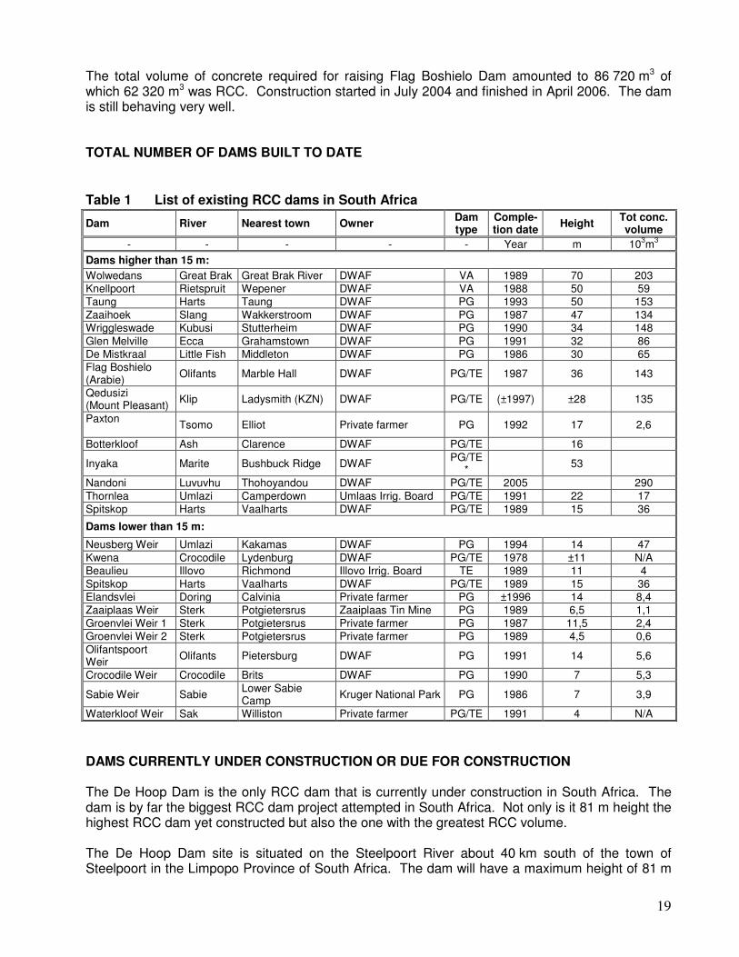
DAMS CURRENTLY UNDER CONSTRUCTION OR DUE FOR CONSTRUCTION The De Hoop Dam is the only RCC dam that is currently under construction in South Africa. The dam is by far the biggest RCC dam project attempted in South Africa. Not only is it 81 m height the highest RCC dam yet constructed but also the one with the greatest RCC volume. The De Hoop Dam site is situated on the Steelpoort River about 40 km south of the town of Steelpoort in the Limpopo Province of South Africa. The dam will have a maximum height of 81 m
20
and an overall length of 1.015 km. It will be an ”all-RCC” gravity dam with a vertical upstream face. The stepped downstream face will have a slope of 0.80:1 (H:V). The 110 m long spillway will have a 6 m freeboard. Current indications are that the dam will be completed by 2012.
Figure 12. Layout plan of the De Hoop Dam. Construction of the proposed Spring Grove Dam is to start towards the end of 2009. This is a very urgent project to augment the water supplies of the Durban-Pietermaritzburg region in the KwaZulu-Natal Province. The Spring Grove Dam will be the main water resource for the Mooi-Mgeni Transfer Scheme Phase 2. The 40 m high composite dam will have a central spillway constructed from RCC and an embankment right flank. The downstream face of the spillway will be stepped. Completion is scheduled for 2011. FUTURE DAMS CONSIDERED South Africa is a water scarce country with an average annual rainfall of less than 500 mm. This is about 300 mm less than the world average of about 800 mm. To complicate things further the greatest economic activities of the country take place in areas that are water scarce in terms of the pressures put on the resources. It is therefore normal practice that water from water rich areas are transferred through inter-basin transfers to areas of intense economic development.
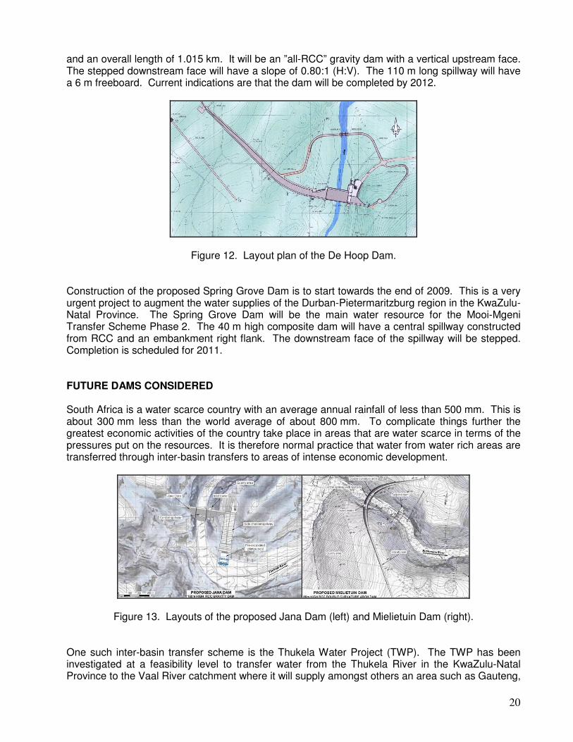
Figure 13. Layouts of the proposed Jana Dam (left) and Mielietuin Dam (right). One such inter-basin transfer scheme is the Thukela Water Project (TWP). The TWP has been investigated at a feasibility level to transfer water from the Thukela River in the KwaZulu-Natal Province to the Vaal River catchment where it will supply amongst others an area such as Gauteng,
21
the economic hub of South Africa. The TWP comprises two major dams from where water will be pumped along a 3.0 m diameter pipeline over the Drakensberg into the Vaal catchment. The proposed Jana Dam, a 160 m high RCC gravity dam on the Thukela River, will be situated near the town of Colenso. The second dam, the proposed Mielietuin Dam, will be situated on the Bushmans River near Weenen. The Bushmans River is a tributary of the Thukela River, South Africa’s second largest river from a water resource point of view. An 85 m high double curvature RCC arch dam has been proposed for the Mielietuin Dam site. On the right bank side the arch will be extended by a straight gravity section. The TWP is competing with Phase 2 of the Lesotho Highlands Water Project (LHWP-2) as the next augmentation scheme for the Vaal supply area. The LHWP-2 is currently being investigated to the same level of detail as that of the TWP and it is expected that a decision will soon be made on which project to implement first. CONCLUSION RCC dams in South Africa has good track records and this gave designers the confidence to keep on exploiting the technique to construct dams. As has been demonstrated RCC has been applied in various ways and it is likely that more and more new uses will come forth in the near future. REFERENCES 1. Hollingworth, F., Hooper, D.J., and Geringer, J.J., "Roller Compacted Concrete Arched Dams,"
International Water Power and Dam Construction, Vol 41, No 11, November 1989. 2. Hollingworth, F., and Geringer, J.J., "Roller Compacted Concrete Arch/Gravity Dams - South
African Experience," Proceedings, ASCE Speciality Conference On Roller Compacted Concrete - Rocky III, San Diego, California, USA, 2-5 February 1992. Paper presented by underlined author.
3. Hollingworth, F., and Geringer, J.J., "Cracking and Leakage In RCC Dams," International Water
Power and Dam Construction, Vol 44, No 2, February 1992. 4. "Rollcrete techniques unique to SA make Wriggleswade Dam a winner", The Civil Engineer in
South Africa, Vol 34, No 1, published as originally written by J.J. Geringer, January 1992. 5. Geringer, J.J., "Wriggleswade - A RCC Dam Designed For Future Raising", Transactions, ICOLD
18, Q70, R46, Durban, November 1994, Vol 3, p725 – 735. 6. Geringer, J.J., "Raising Dams With The Alternative RCC Placing Technique Used At
Wriggleswade Dam", Transactions, ICOLD 18, Prepared contribution on Q70, R46, Durban, November 1994, Vol 5, p460 - 462.
7. Geringer, J.J., "The evolution and development of RCC dams in South Africa", The International
Journal on Hydropower and Dams, October 1994. 8. Geringer, J.J., and du Buisson, N.J., "Neusberg: An RCC Weir Across South Africa's Largest
River", International Journal on Hydropower and Dams, September 1995, p53-60.
22
9. Geringer, J.J., "The Design and Construction of the Groutable Crack Joints of Wolwedans Dam", Proceedings, International Symposium on Roller Compacted Concrete Dams, Santander, Spain, 2-4 October 1995, Volume 2, p1015-1036.
10. Geringer, J.J., "The Design and Construction of RCC Dams in Southern Africa", Post-symposium
proceedings, International Symposium on Roller Compacted Concrete Dams, Santander, Spain, 2-4 October 1995, Volume 3, p1459-1495.
11. Lesotho Highlands Water Project: Contract No. HDTC-13: Upgrading of Ash River Stage 2 and 2A Structures: Construction Report, Highlands Delivery Tunnel Consultants, March 2002.
12. Nitzsche, W.M.m Druyts, F.H.W.M., Hume, P.K., Elges, H.F.W.K., “Sabie River Government Water
Scheme (Phase 1), Inyaka Dam and Appurtenant Works, Construction Completion Report”, Department of Water Affairs and Forestry, Report No. X301/75/ED 03, August 2003.