TEM SPECIMEN PREPARATION The art of specimen preparation; TEM an introduction: NanoLab Twente Specimen preparation is an essential part of Transmission Electron Microscopy ( ). Without a good specimen, no . specimens must be electron TEM TEM TEM transparent and representative of the material one wants to study. In most cases it is desirable to have specimens which are uniformly thin, stable under the electron beam, conducting and nonmagnetic. Clear exceptions are of course magnetic materials for which magnetic properties have to be investigated, e.g., with Lorentz Microscopy, and metals or alloys in which crystal defects (dislocations) have to be studied; they should not be made too thin. There are many ways to prepare specimens for . The chosen method will depend on both the type of material TEM and the information one needs to obtain. Most important aspect to bear in mind is that the preparation technique must never affect what one observes or measures. Specimen preparation is an extremely broad subject. Upon surveying the literature, numerous books have been devoted to this topic alone. For an extensive overview of specimen preparation techniques, including TEM corresponding literature references, may we refer to an excellent source of information on the web, created by Jeanne Ayache and coworkers (Ref. [1]). MESA TEM SEM + NanoLab has a well equipped set of facilities for inorganic / sample preparation, including the following techniques: Cutting, grinding, lapping, polishing D TEM imple grinding ( only) M TEM GATAN PIPS SEM PECS aterial removal by Argon ion sputtering ( : , : ) Standard metal carbon/metal coating H GATAN PECS igh resolution carbon/metal coating ( ) W TRIPOD TEM edge or polishing ( only) F FIB ocused Ion Beam ( ) For the observation of samples in cross-section, + NanoLab is specialised in MESA the technique Dimple Grinding/Polishing and Argon ion sputtering, as depicted on the following pages 2 - 4. This is in particular applicable for „blanket“ films on a substrate. With precise control during the final stages of the thinning process, large, uniformly thin, electron transparent areas can be achieved, - with a minimum amount of damage - (see, e.g., Ref. [2]). Especially when care is taken that the Argon ion thinning stage is terminated just before an etch hole is created (see left XTEM image on page 2). In this case it is essential that the operator keeps his/her eye continuously on the ion thinning process. In Ref. [3] we have been able to show electron transparency beyond 6 micron. For cross-sectional observation of more complex samples, such as „device-like“ systems, specimen preparation by is often the only viable alternative, and TEM FIB nowadays the preferred method. Applicable to a large variety of materials (virtually all than can be ion milled). REFERENCES [1] web site „Transmission Electron Microscopy ( ): sample preparation guide“, TEM by Jeanne Ayache and coworkers, http://temsamprep.in2p3.fr/ [2] E.G. Keim, M.D. Bijker, J.C. Lodder, J. Vac. Sci. Technol.A19(4), Jul/Aug 2001. [3] E.G. Keim, L.T. Nguyen, J.C. Lodder, Proceedings Microscopy & Microanalysis 2002 Meeting, Quebec City, Quebec ( ), August 4-8, 2002, pages 1346 - CA CD 1347 . 0-521-82405-2. CD ISBN [4] Illustrations used on page 4, from/inspired by: M. Kawasaki, T. Yoshioka, M. Shiojiri, J. Electron Microscopy 48(2) (1999) 131-137. Associated text is however, adapted to our modified recipe of Dimple Grinding and Argon ion etching.
Transcript
TE
M S
PE
CIM
EN
PR
EP
AR
AT
ION
The art of specimen preparation;TEMan introduction:
NanoLab Twente
Specimen preparation is an essential part of Transmission Electron Microscopy( ). Without a good specimen, no . specimens must be electronTEM TEM TEMtransparent and representative of the material one wants to study. In most cases itis desirable to have specimens which are uniformly thin, stable under the electronbeam, conducting and nonmagnetic. Clear exceptions are of course magneticmaterials for which magnetic properties have to be investigated, e.g., with LorentzMicroscopy, and metals or alloys in which crystal defects (dislocations) have to bestudied; they should not be made too thin. There are many ways to preparespecimens for . The chosen method will depend on both the type of materialTEMand the information one needs to obtain. Most important aspect to bear in mind isthat the preparation technique must never affect what one observes or measures.
Specimen preparation is an extremely broad subject. Upon surveying the literature,numerous books have been devoted to this topic alone.
For an extensive overview of specimen preparation techniques, includingTEMcorresponding literature references, may we refer to an excellent source ofinformation on the web, created by Jeanne Ayache and coworkers (Ref. [1]).
MESA TEM SEM+ NanoLab has a well equipped set of facilities for inorganic /sample preparation, including the following techniques:� Cutting, grinding, lapping, polishing� D TEMimple grinding ( only)� M TEM GATAN PIPS SEM PECSaterial removal by Argon ion sputtering ( : , : )� Standard metal carbon/metal coating� H GATAN PECSigh resolution carbon/metal coating ( )� W TRIPOD TEMedge or polishing ( only)� F FIBocused Ion Beam ( )
For the observation of samples in cross-section, + NanoLab is specialised inMESAthe technique Dimple Grinding/Polishing and Argon ion sputtering, as depicted onthe following pages 2 - 4. This is in particular applicable for „blanket“ films on asubstrate. With precise control during the final stages of the thinning process,large, uniformly thin, electron transparent areas can be achieved, - with a minimumamount of damage - (see, e.g., Ref. [2]). Especially when care is taken that theArgon ion thinning stage is terminated just before an etch hole is created (see leftXTEM image on page 2). In this case it is essential that the operator keeps his/hereye continuously on the ion thinning process. In Ref. [3] we have been able toshow electron transparency beyond 6 micron.
For cross-sectional observation of more complex samples, such as „device-like“systems, specimen preparation by is often the only viable alternative, andTEM FIBnowadays the preferred method. Applicable to a large variety of materials (virtuallyall than can be ion milled).
REFERENCES[1] web site „Transmission Electron Microscopy ( ): sample preparation guide“,TEMby Jeanne Ayache and coworkers, http://temsamprep.in2p3.fr/
[2] E.G. Keim, M.D. Bijker, J.C. Lodder, J. Vac. Sci. Technol. A19(4), Jul/Aug 2001.
[3] E.G. Keim, L.T. Nguyen, J.C. Lodder, Proceedings Microscopy & Microanalysis2002 Meeting, Quebec City, Quebec ( ), August 4-8, 2002, pages 1346 -CA CD1347 . 0-521-82405-2.CD ISBN
[4] Illustrations used on page 4, from/inspired by: M. Kawasaki, T. Yoshioka, M.Shiojiri, J. Electron Microscopy 48(2) (1999) 131-137. Associated text is however,adapted to our modified recipe of Dimple Grinding and Argon ion etching.
TE
M S
PE
CIM
EN
PR
EP
AR
AT
ION
The technique of Dimple Grinding/Polishing andArgon ion etching to prepare cross-sectionalTEMspecimens; a basic outline:
Step 1
Step 2
Step 3
Step 4
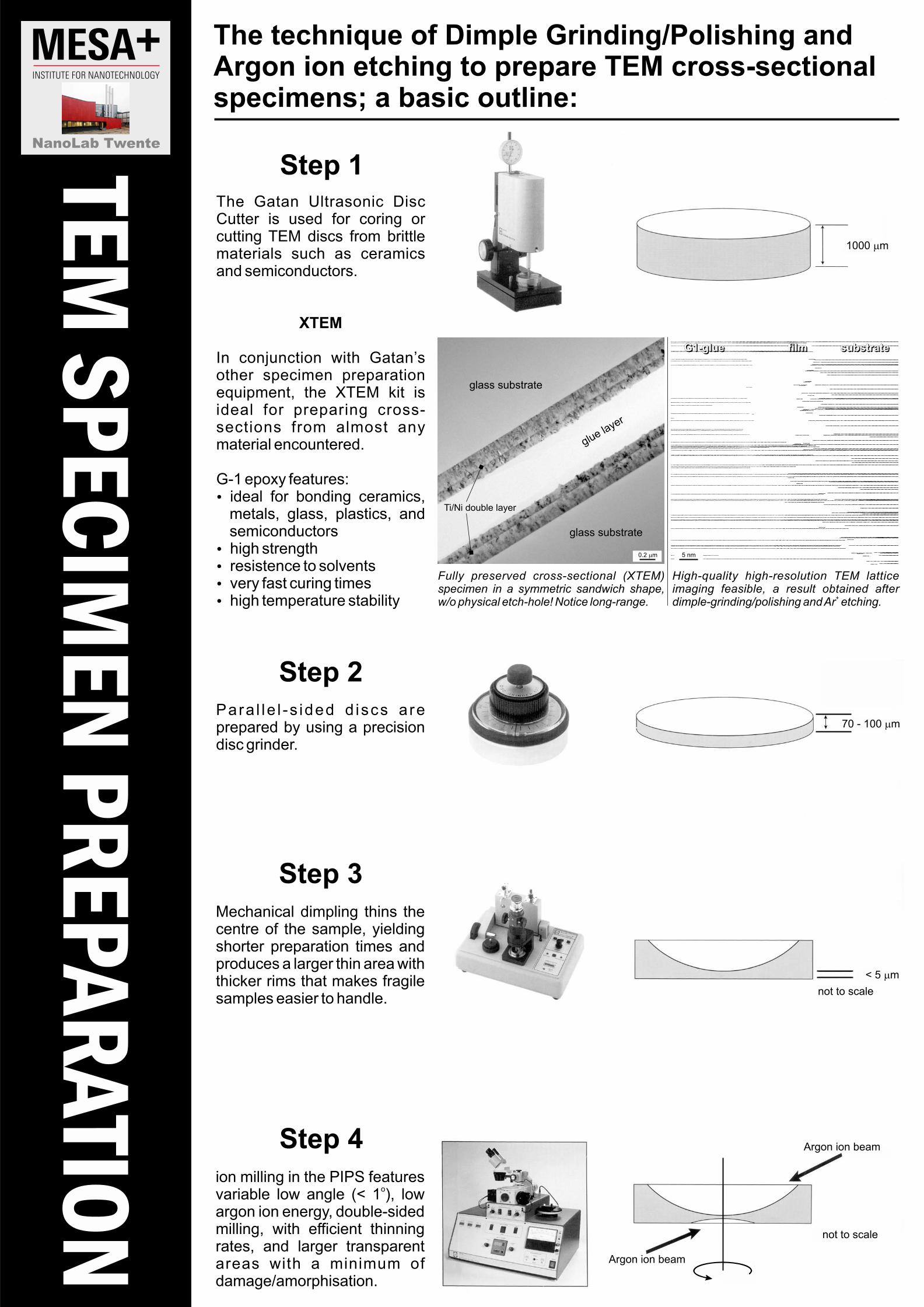
The Gatan Ultrasonic DiscCutter is used for coring orcutting discs from brittleTEMmaterials such as ceramicsand semiconductors.
XTEM
In conjunction with Gatan’sother specimen preparationequipment, the kit isXTEMideal for preparing cross-sections from almost anymaterial encountered.
G-1 epoxy features:� ideal for bonding ceramics,
metals, glass, plastics, andsemiconductors
� high strength� resistence to solvents� very fast curing times� high temperature stability
Para l le l -s ided d iscs areprepared by using a precisiondisc grinder.
Mechanical dimpling thins thecentre of the sample, yieldingshorter preparation times andproduces a larger thin area withthicker rims that makes fragilesamples easier to handle.
ion milling in the featuresPIPSvariable low angle (< 1 ), low
o
argon ion energy, double-sidedmilling, with efficient thinningrates, and larger transparentareas with a minimum ofdamage/amorphisation.
G1-glue film substrateG1-glue film substrateG1-glue film substrate
NanoLab Twente
70 - 100 m�
< 5 m�
not to scale
not to scale
Argon ion beam
Argon ion beam
1000 m�
5 nm
glue layer
glass substrate
glass substrate
Ti/Ni double layer
0.2 m�
Fully preserved cross-sectional ( )XTEMspecimen in a symmetric sandwich shape,w/o physical etch-hole! Notice long-range.
High-quality high-resolution latticeTEMimaging feasible, a result obtained afterdimple-grinding/polishing andAr etching.
+
Ar+
Ar+
TE
M S
PE
CIM
EN
PR
EP
AR
AT
ION
The technique of Dimple Grinding/Polishing andArgon ion etching to prepare cross-sectional TEMspecimens; shown in 4 easy Steps:
Step 4
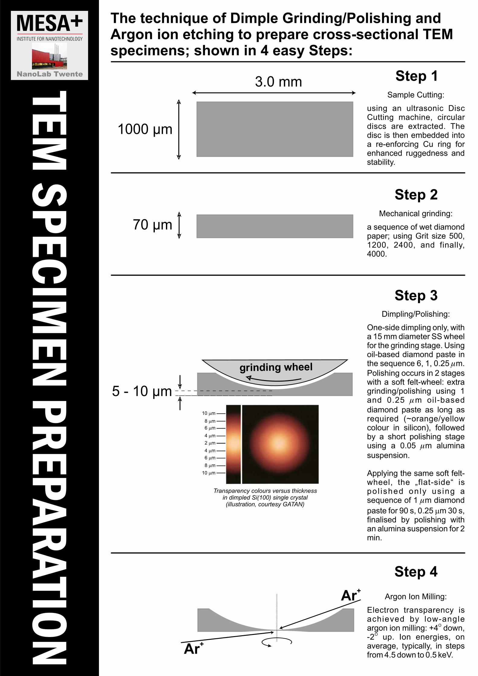
Argon Ion Milling:
Electron transparency isachieved by low-angleargon ion milling: +4 down,
O
-2 up. Ion energies, onO
average, typically, in stepsfrom 4.5 down to 0.5 keV.
5 - 10 µm
grinding wheel
3.0 mm
1000 µm
70 µm
Step 1
Step 2
Sample Cutting:
using an ultrasonic DiscCutting machine, circulardiscs are extracted. Thedisc is then embedded intoa re-enforcing Cu ring forenhanced ruggedness andstability.
Mechanical grinding:
a sequence of wet diamondpaper; using Grit size 500,1200, 2400, and finally,4000.
Step 3Dimpling/Polishing:
One-side dimpling only, witha 15 mm diameter wheelSSfor the grinding stage. Usingoil-based diamond paste inthe sequence 6, 1, 0.25 m.�
Polishing occurs in 2 stageswith a soft felt-wheel: extragrinding/polishing using 1and 0.25 m oil-based�
diamond paste as long asrequired (~orange/yellowcolour in silicon), followedby a short polishing stageusing a 0.05 m alumina�
suspension.
Applying the same soft felt-wheel, the „flat-side“ ispo l ished only us ing asequence of 1 m diamond�
paste for 90 s, 0.25 m 30 s,�
finalised by polishing withan alumina suspension for 2min.
Transparency colours versus thicknessin dimpled Si(100) single crystal(illustration, courtesy )GATAN
NanoLab Twente
10 m�
8 m�
6 m�
4 m�
2 m�
4 m�
6 m�
8 m�
10 m�
TE
M S
PE
CIM
EN
PR
EP
AR
AT
ION
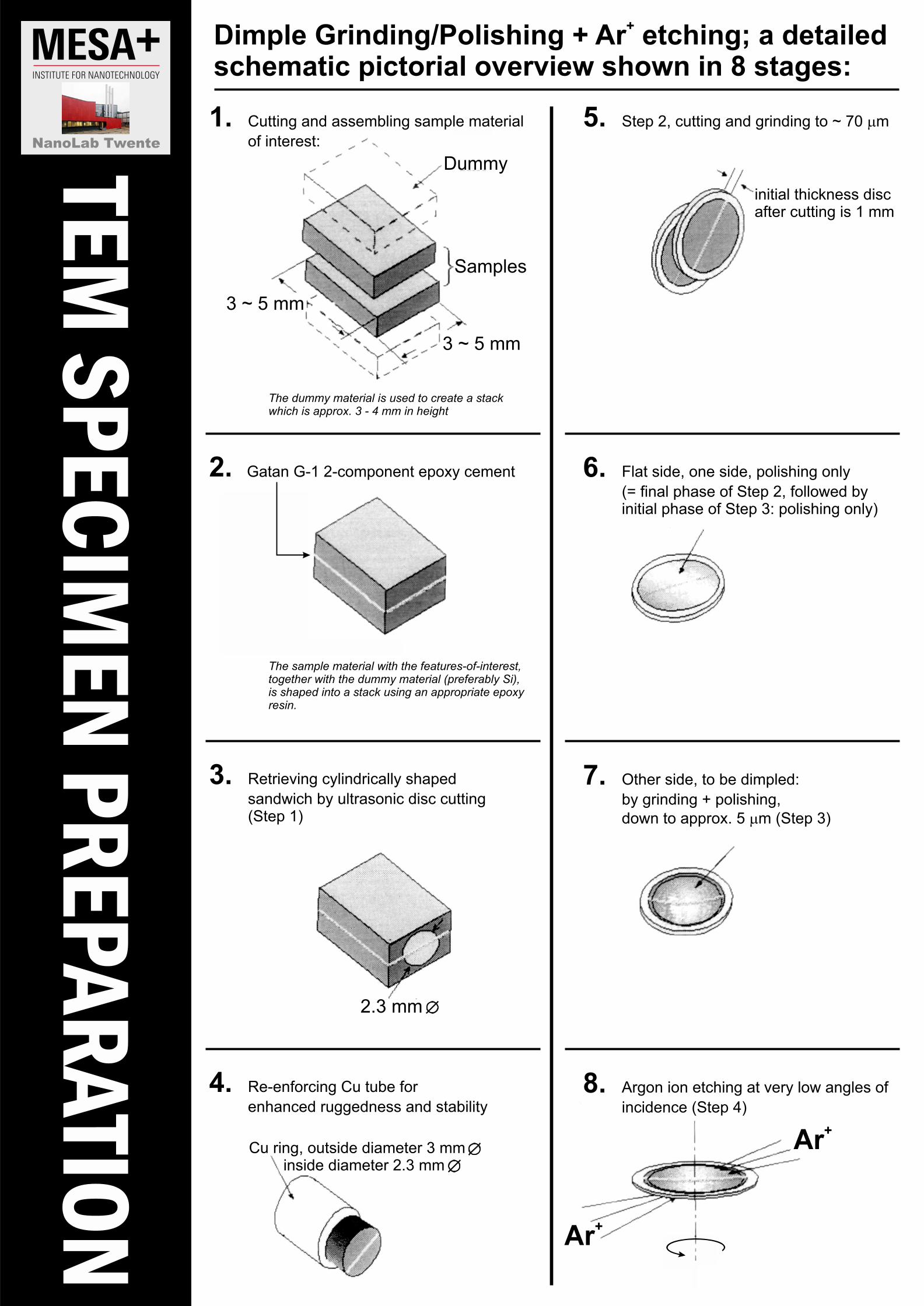
Dimple Grinding/Polishing + Ar etching; a detailed+
schematic pictorial overview shown in 8 stages:
6. Flat side, one side, polishing only
(= final phase of Step 2, followed byinitial phase of Step 3: polishing only)
7. Other side, to be dimpled:
by grinding + polishing,
down to approx. 5 m (Step 3)�
8. Argon ion etching at very low angles of
incidence (Step 4)
2.
3. Retrieving cylindrically shaped
sandwich by ultrasonic disc cutting(Step 1)
4. Re-enforcing Cu tube for
enhanced ruggedness and stability
Dummy
Samples
3 ~ 5 mm
3 ~ 5 mm
2.3 mm
initial thickness discafter cutting is 1 mm
Cu ring, outside diameter 3 mminside diameter 2.3 mm
Ar+
Ar+
The dummy material is used to create a stackwhich is approx. 3 - 4 mm in height
The sample material with the features-of-interest,together with the dummy material (preferably Si),is shaped into a stack using an appropriate epoxyresin.