This document and trademark(s) contained herein are protected by law as indicated in a notice appearing later in this work. This electronic representation of RAND intellectual property is provided for non-commercial use only. Unauthorized posting of RAND PDFs to a non-RAND Web site is prohibited. RAND PDFs are protected under copyright law. Permission is required from RAND to reproduce, or reuse in another form, any of our research documents for commercial use. For information on reprint and linking permissions, please see RAND Permissions. Limited Electronic Distribution Rights This PDF document was made available from www.rand.org as a public service of the RAND Corporation. 6 Jump down to document THE ARTS CHILD POLICY CIVIL JUSTICE EDUCATION ENERGY AND ENVIRONMENT HEALTH AND HEALTH CARE INTERNATIONAL AFFAIRS NATIONAL SECURITY POPULATION AND AGING PUBLIC SAFETY SCIENCE AND TECHNOLOGY SUBSTANCE ABUSE TERRORISM AND HOMELAND SECURITY TRANSPORTATION AND INFRASTRUCTURE WORKFORCE AND WORKPLACE The RAND Corporation is a nonprofit research organization providing objective analysis and effective solutions that address the challenges facing the public and private sectors around the world. Visit RAND at www.rand.org Explore RAND National Defense Research Institute View document details For More Information Purchase this document Browse Books & Publications Make a charitable contribution Support RAND
Transcript
This document and trademark(s) contained herein are protected by law as indicated in a notice appearing later in this work. This electronic representation of RAND intellectual property is provided for non-commercial use only. Unauthorized posting of RAND PDFs to a non-RAND Web site is prohibited. RAND PDFs are protected under copyright law. Permission is required from RAND to reproduce, or reuse in another form, any of our research documents for commercial use. For information on reprint and linking permissions, please see RAND Permissions.
Limited Electronic Distribution Rights
This PDF document was made available from www.rand.org as a public
service of the RAND Corporation.
6Jump down to document
THE ARTS
CHILD POLICY
CIVIL JUSTICE
EDUCATION
ENERGY AND ENVIRONMENT
HEALTH AND HEALTH CARE
INTERNATIONAL AFFAIRS
NATIONAL SECURITY
POPULATION AND AGING
PUBLIC SAFETY
SCIENCE AND TECHNOLOGY
SUBSTANCE ABUSE
TERRORISM AND HOMELAND SECURITY
TRANSPORTATION ANDINFRASTRUCTURE
WORKFORCE AND WORKPLACE
The RAND Corporation is a nonprofit research organization providing objective analysis and effective solutions that address the challenges facing the public and private sectors around the world.
This product is part of the RAND Corporation technical report series. Reports may
include research findings on a specific topic that is limited in scope; present discus-
sions of the methodology employed in research; provide literature reviews, survey
instruments, modeling exercises, guidelines for practitioners and research profes-
sionals, and supporting documentation; or deliver preliminary findings. All RAND
reports undergo rigorous peer review to ensure that they meet high standards for re-
search quality and objectivity.
NATIONAL DEFENSE RESEARCH INSTITUTE
TECHNICAL REPORT
A Methodology for Estimating the Effect of Aircraft Carrier Operational Cycles on the Maintenance Industrial Base
Roland J. Yardley • John F. Schank • James G. Kallimani
Raj Raman • Clifford A. Grammich
Prepared for the United States Navy
Approved for public release; distribution unlimited
The RAND Corporation is a nonprofit research organization providing objective analysis and effective solutions that address the challenges facing the public and private sectors around the world. RAND’s publications do not necessarily reflect the opinions of its research clients and sponsors.
All rights reserved. No part of this book may be reproduced in any form by any electronic or mechanical means (including photocopying, recording, or information storage and retrieval) without permission in writing from RAND.
Published 2007 by the RAND Corporation1776 Main Street, P.O. Box 2138, Santa Monica, CA 90407-2138
1200 South Hayes Street, Arlington, VA 22202-50504570 Fifth Avenue, Suite 600, Pittsburgh, PA 15213-2665
RAND URL: http://www.rand.org/To order RAND documents or to obtain additional information, contact
The research described in this report was prepared for the United States Navy. The research was conducted in the RAND National Defense Research Institute, a federally funded research and development center sponsored by the Office of the Secretary of Defense, the Joint Staff, the Unified Combatant Commands, the Department of the Navy, the Marine Corps, the defense agencies, and the defense Intelligence Community under Contract W74V8H-06-C-0002.
Library of Congress Cataloging-in-Publication Data
A methodology for estimating the impact of aircraft carrier operational cycles on the maintenance industrial base /Roland J. Yardley ... [et al.].
p. cm. Includes bibliographical references. ISBN 978-0-8330-4182-1 (pbk. : alk. paper) 1. Aircraft carriers—United States—Maintenance and repair. 2. United States. Navy Operational readiness. 3. Queuing theory. I. Yardley, Roland J.
V874.3.M48 2007355.2'6—dc22
2007024857
Left cover image: The Nimitz-class aircraft carrier USS Ronald Reagan,U.S. Navy photo by Photographer’s Mate 1st Class James Thierry
Right cover image: The Nimitz-class aircraft carrier USS George Washington,U.S. Navy photo by Mass Communication Specialist 2nd Class Peter D. Blair
The U.S. Navy has implemented the Fleet Response Plan (FRP) to allow more variability in the aircraft carrier fleet’s operational, training, and maintenance schedules. By increasing the operational availability of aircraft carriers, the FRP permits an enhanced surge capability for carrier strike groups to meet defense requirements. Although regularly scheduled six-month deployments still occur, aircraft carriers may also be called upon to deploy at other times during their maintenance and training cycles.
As the changes associated with the FRP were unfolding, the Program Executive Office (PEO) for Aircraft Carriers tasked the RAND Corporation to examine the effect of mainte-nance demands under different operational cycles on the industrial base for aircraft carrier maintenance. We vary the cycle length and maintenance demands, and examine the effects to determine whether workload demand exceeds the supply of workers or whether the supply of workers exceeds the demand for work. We also examine the effect of different cycle lengths on operational availability of the aircraft carrier fleet. RAND researchers were asked to examine the effect on the maintenance industrial base of the extension of time between depot main-tenance availabilities, the increased use of continuous maintenance (CM) periods, and the potential reductions in the size of the aircraft carrier fleet. For the examination, we developed a model based on inputs from the Naval Sea Systems Command (NAVSEA); the Carrier Plan-ning Activity (CPA), who oversee the planning of aircraft carrier depot work packages and execution of life-cycle maintenance and modernization; and Naval Shipyard officials.
This report should be of interest to persons concerned with the maintenance, opera-tional availability, and readiness of Navy aircraft carriers under the FRP, including those in NAVSEA, the Fleet Forces Command, and Type Commanders.
The research was sponsored by the PEO Aircraft Carriers and conducted within the Acquisition and Technology Policy Center of the RAND National Defense Research Institute, a federally funded research and development center sponsored by the Office of the Secretary of Defense, the Joint Staff, the Unified Combatant Commands, the Department of the Navy, the Marine Corps, the defense agencies, and the defense Intelligence Community.
For more information on RAND’s Acquisition and Technology Policy Center, con-tact the Director, Philip Antón. He can be reached by email at [email protected]; by phone at 310-393-0411, extension 7798; or by mail at the RAND Corporation, 1776 Main Street, Santa Monica, California 90407-2138. More information about RAND is available at www.rand.org.
Over the next two decades, the United States Navy will, at any one time, have a fleet of ten to 12 aircraft carriers. Of these, two or three will be continuously deployed and on-station at any one time in its major overseas operational areas of the Mediterranean, the Indian Ocean and Persian Gulf region, and the Western Pacific, in support of combatant commanders. In addition, the Navy intends to surge carriers (including those already deployed) so that a total of six carriers can be provided to combatant commanders within 30 days and another carrier within 90 days.
The ability of the Navy to meet all these requirements is constrained both by the six-month limit on deployment length and by the intensive training and maintenance demands of aircraft carriers. The Navy has considered the six-month limit on deployments and the predict-ability of Carrier Strike Groups (CSGs) rotation key to maintaining forward presence while meeting personnel recruiting and retention goals. In addition, maintenance is constantly being performed on aircraft carriers, with nearly a third of a carrier’s lifetime being spent either pre-paring for or actually in depot-level repair availabilities, in which it is not deployable.
Aircraft carriers are maintenance-intensive, and maintenance is constantly being per-formed on them. The most effective strategy for executing maintenance on aircraft carriers is through continuous maintenance and prevention of deferred work that would require long, out-of-service maintenance periods. Aircraft carriers must be maintained at a level of material readiness to support fleet operational requirements.
Carrier repair and maintenance requirements are distributed according to the Incremen-tal Maintenance Plan (IMP). The IMP is a continuous-maintenance strategy, whereby main-tenance and modernization depot availabilities are performed each cycle,1 to ensure the mate-rial condition of the Nimitz class throughout its service life. The IMP cycle was 24 months in duration. Over time, the 24-month basis for IMP has been lengthened in practice to 27 months. The 27-month cycle was, in turn, formalized in a Fleet Response Plan. A distinguish-ing feature of the FRP was the integration of some training during maintenance to enable a ship to achieve a higher state of readiness sooner after maintenance is completed and to sustain that readiness longer, which increases the carrier’s operational availability.
1 A cycle is the length of time that a carrier takes as it progresses through maintenance, training, deployment, and the sustainment of readiness both before and after deployment. The cycle length is measured from the end of one maintenance depot availability to the end of the next.
This increase in operational availability or surge readiness comes at a cost. With the con-straint of conducting one deployment per maintenance cycle, the proportion of time that a carrier is actually deployed decreases as the cycle length is increased.
If the duration of a maintenance cycle is varied, there will be a trade-off between the proportion of a carrier’s lifetime that is spent on deployment, the number of depot-level main-tenance periods a carrier undergoes, and the proportion of time a carrier and its crew are surge-ready. As the cycle duration is increased, the proportion of lifetime spent on deployment and the number of depot-level maintenance periods decrease, whereas the proportion of time the carrier and its crew are surge-ready will increase. RAND researchers characterized these trade-offs and evaluated the impact they would have on the maintenance industrial base.
Our analysis focused on those demands that the ten Nimitz-class carriers that will be in operation over the next two decades (including the nine currently operating) will place on the maintenance industrial base. In particular, we focused on the effects that varying maintenance cycles for carriers would have on the workers at Norfolk Naval Shipyard (NNSY) and Puget Sound Naval Shipyard and Intermediate Maintenance Facility (PSNS & IMF) who support carrier maintenance.
To measure the effects of these changes on the maintenance industrial base, we use a model to estimate the magnitude and timing of work (demand) on all ships in the yards making up the maintenance industrial base. To understand the workforce implications of different maintenance cycles at the shipyards, we modified a RAND model that was initially used to analyze changes in ship-acquisition programs.2 The model first estimates the workload demand at the trade-skill level (welders, electricians, etc.) over time at each of the shipyards. It includes workload demands resulting from maintenance, modernization, decommission-ing, and other projects for the various ship classes supported by a shipyard. The model uses shipyard-provided current and future workforce supply at the shipyards and compares supply of workers to the workload demands for the options we examined, to illustrate how the work-force must be adjusted to accomplish the desired workload.
We use the model to compare the projected supply of skilled workers to the demand to understand the challenges in managing the workforce under different maintenance policies. We estimate the effects of a 27-, 32-, and 36-month maintenance/training cycle on managing the demands on the maintenance industrial base.
We drew from NAVSEA’s Carrier Planning Activity’s3 analysis that estimates that, by extending the maintenance cycle to 32 months and eliminating some Planned Incremental Availabilities (PIAs) and Docking Planned Incremental Availabilities (DPIAs), the longer maintenance cycles can reduce the number of maintenance man-days a carrier will need over its lifetime by about 500,000. Increasing the cycle duration will also decrease the total number of depot availabilities. The remaining depot availabilities (PIAs/DPIAs) may require more maintenance days, causing demand on the shipyards to spike. The introduction of
2 Mark V. Arena, John F. Schank, and Megan Abbott, The Shipbuilding and Force Structure Analysis Tool: A User’s Guide,Santa Monica, Calif.: RAND Corporation, MR-1743-NAVY, 2004.3 The CPA develops the maintenance and modernization work packages for aircraft carrier depot availabilities.
xii A Methodology for Estimating the Effect of Aircraft Carrier Operational Cycles
continuous-maintenance periods can help offset the depot maintenance packages, keeping them from becoming too large for the shipyards to handle.
We also consider an option in which the total maintenance workload over the life of an aircraft carrier was fixed and independent of the length of the cycle. We added the total main-tenance and repair man-days for the PIAs and DPIAs under the 27-month schedule, and we distributed this higher total of man-days across the PIAs and DPIAs in both the 32- and 36-month schedules for a Fixed Lifetime Maintenance (FLM) case.
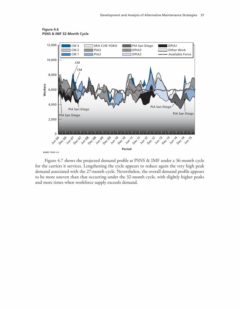
Through the analysis of CPA-estimated maintenance demands and the FLM option, RAND researchers identified some carrier maintenance scenarios under which projected work-load could meet or exceed the number of available workers at both NNSY and PSNS & IMF. Under some carrier maintenance scenarios, the projected workload at NNSY could exceed more than 9,000 workers at some point in the next decade, or twice the number of available workers in the yard, and that at PSNS & IMF could exceed 10,000 workers, or about two-thirds more than the number of available workers in the yard. Surplus demand would be still higher should the longer maintenance cycle fail to reduce the total number of maintenance man-days a carrier requires in its lifetime.
As an example, Figure S.1 represents the PSNSY & IMF 32-month cycle using the CPA-estimated maintenance demands. The black-and-white curve at approximately the
Figure S.1PSNS & IMF 32-Month Cycle
0
2,000
4,000
6,000
8,000
10,000
12,000
Wo
rker
s
Period
Jun 12
Dec 11
Jun 11
Dec 10
Jun 10
Dec 0
9
Jun 0
9
Dec 0
8
Jun 0
8
Dec 07
Jun 07
Dec 0
6
Jun 0
6
Dec 12
Jun 13
Jun 14
Dec 13
Dec 14
Jun 15
RAND TR480-S.1
DPIA2DPIA3PIA San Diego
PIA2PIA3SRA CVN YOKO
CM 1CM 2CM 3
Other WorkDPIA1
Available Force
CM
CM
PIA San Diego
PIA San DiegoPIA San Diego
PIA San Diego
Summary xiii
6,000-workers level represents the available workforce. While the workload demand exceeds the available force, the excess demand could be met through scheduling overtime and/or outsourcing the work.
Figure S.2 illustrates how the FLM option affects demand at NNSY under a 36-month cycle. Under this scenario, peak demand exceeds 8,000 workers several times throughout the next decade, including most of 2014 and 2015. While NNSY can manage excess demands through overtime, hiring of temporary workers, and subcontracting, high and sustained peaks (overdemand) stress the shipyard’s ability to meet maintenance demands.
Changing the maintenance cycle by increasing the time between depot availabilities also affects the amount of time in which a shipyard has an oversupply of workers. Oversupply would exist at some point over the next decade at both shipyards and be more pronounced at PSNS & IMF under a 36-month cycle with unchanged man-day requirements.
Overall, we found that a 32-month cycle, should it be able to reduce total maintenance demands across the life of a carrier as projected, could do more to shift monthly distribution of workload throughout the next decade to a range in which neither supply of or demand for maintenance exceeds the other by more than 10 percent. The surplus of supply or demand could be reduced by shifting work among shipyards or sharing workers through the One Shipyard concept.
Figure S.2NNSY 36-Month Cycle: FLM Case
DPIA1DPIA2PIA San Diego
PIA1PIA2PIA3
CM 1CM 2CM 3 Other Work
Avail Force
0
2,000
4,000
6,000
8,000
10,000
12,000
Wo
rker
s
Period
Jun 12
Dec 11
Jun 11
Dec 10
Jun 10
Dec 0
9
Jun 0
9
Dec 0
8
Jun 0
8
Dec 07
Jun 07
Dec 0
6
Jun 0
6
Dec 12
Jun 13
Jun 14
Dec 13
Dec 14
Jun 15
RAND TR480-S.2
PIA3 PIA2
PIA2
PIADPIA2
DPIA2
PIA2
PIA3
xiv A Methodology for Estimating the Effect of Aircraft Carrier Operational Cycles
Our assessment also examined the effects that different maintenance cycles would have on the number of aircraft carriers that are deployed or deployable in coming decades. Figure S.3 indicates that the number of surge-ready carriers increases as cycle length increases. Our modeling indicates that as the cycle length increases, with the limitation of a single six-month deployment per cycle, the number of deployed carriers decreases. Longer cycle times make car-riers deployable for greater lengths of time, but we constrained our modeling to enable only a single six-month limit4 on deployments for the one planned deployment between depot-level availabilities. In practice, we realize that aircraft carriers could and most likely would be deployed to a greater extent.5 The increased number of average surge-ready carriers with increased cycle length enables more Nuclear Aircraft Carriers (CVNs) to be surged.
In sum, each cycle has its own features, the appeal of which may depend on operational and industrial goals. The 27-month cycle would provide a higher average number of carri-ers deployed at any one time, but there would be fewer additional deployable carriers. The 32-month cycle would minimize periods of strain on the maintenance industrial base. The 36-month cycle would have the highest number of deployable carriers but, assuming a six-month limit on deployments in a maintenance cycle, the lowest average number of carriers on deployment at any one time. The trade-off between deployed and deployable carriers could be
Figure S.3Summary of Operational States of U.S. Aircraft Carriers for 27-Month, 32-Month, and 36-Month Cycles
RAND TR480-S.3
27-month 32-month 36-month
Cycle duration
0
2
4
6
8
10
12
Ave
rag
e n
um
ber
of
carr
iers
,b
y re
adin
ess
stat
e
3.63
1.48
3.52
2.37
3.25
1.41
4.21
2.13
3.16
1.17
4.72
1.95
MaintenanceTraining
E-surge/surgeDeployed
4 At the start of our study, personnel-tempo policy limited the length of deployments to six months, with a minimum of 12 months’ time between deployments. A recent policy decision allows for an increased deployment length and reduced time between deployments. 5 The impact of an increased number of deployments (and underway time) per cycle would increase maintenance demands. Analysis of the impact of increased deployments on aircraft carrier maintenance demands will be evaluated in follow-on work.
Summary xv
modified by changing deployment lengths, whereas changing deployment cycles can also strain or relieve the maintenance industrial base.
xvi A Methodology for Estimating the Effect of Aircraft Carrier Operational Cycles
Acknowledgments
We gratefully acknowledge the assistance of the staff of the Carrier Planning Activity, Chesa-peake, Virginia. CAPT Michael Gomori, Nick D’Amato, Valerie Howe, Brad Toncray, Lew Rankin, Gregg Baumeier, and Bob Bolden assisted us in addressing the planning needed to meet myriad aircraft carrier maintenance demands. The Naval Shipyard planners provided the research team with data on workforce management and work accomplishment, as well as insights on the data’s meaning and limitations. We are particularly grateful to CAPT Neil Stubits, Jim Shoemaker, LCDR Jerry Legere, Bill Kockler, Mark Peters, and Ken Finley of Norfolk Naval Shipyard. We appreciate the support of Chris Hughes, Jeff Cochran, and Marie Almerol of Puget Sound Naval Shipyard for their comments, support, and data. We thank the staff of Northrop Grumman Newport News, including Bernie Clark, Danny Hurley, Ben Robison, and Bill Docalovich, who met with us and provided insights into the supply and demand issues affecting their workforce. Kelly Powers, NAVSEA 08 (Nuclear Propulsion), provided us with a better understanding of current approaches to meeting nuclear engineering maintenance demands. We also appreciate the advice provided by Steve Perkins of NAVSEA 04 (Logistics, Maintenance, and Industrial Operations). We gratefully acknowledge the sup-port, guidance, and direction provided by Brian Persons and CAPT Thomas Moore from our sponsoring office.
At RAND, this project benefited from the thoughts and suggestions of RAND colleagues Tal Manvel and John Birkler. We appreciate the extensive and thoughtful technical review of our earlier draft of the report by Robert Murphy and Brien Alkire. Their insightful comments helped strengthen the overall report. We appreciate the thoughtful advice and suggestions of our editor, Marian Branch. We also acknowledge and appreciate the administrative support provided by Vicki Wunderle.
PSNS & IMF Puget Sound Naval Shipyard and Intermediate Maintenance Facility
RCOH refueling complex overhaul
SRA Selected Restricted Availability
SSBN ballistic-missile submarine, nuclear-powered
SSGN Guided Missile Submarine
SSN Attack Submarine
TSTA tailored ship training availability
xx A Methodology for Estimating the Effect of Aircraft Carrier Operational Cycles
USS United States Ship
WARR Workload Allocation and Resource Report
Abbreviations xxi
1
CHAPTER ONE
Introduction
Background
Aircraft carriers are maintenance-intensive, and maintenance is constantly being performed on carriers (as well as on other ships of the fleet). An aircraft carrier’s crew routinely performs pre-ventive and corrective maintenance. In addition, while a ship is at home port (and even while a carrier is under way), shipyards as well as other technical authorities routinely have personnel on the aircraft carrier to troubleshoot, repair, and/or replace equipment.
The most effective strategy for executing maintenance on aircraft carriers is through a continuous-maintenance (CM) process that prevents maintenance backlogs requiring long, out-of-service maintenance periods. As operational demands increase, the need to continuously accomplish maintenance and prevent backlogs is more important than ever.1 Aircraft carriers must be maintained at a level of material readiness to support fleet operational requirements.
In recent decades, the U.S. Navy has maintained a continuous or near-continuous forward-deployed presence in three major overseas operational areas: the Mediterranean, the Indian Ocean and Persian Gulf region, and the Western Pacific. It has done so through six-month deployments of Carrier Strike Groups (CSGs).2 A CSG transits to an operating area, operates on-station in that area until relieved by another CSG, and then returns to home port. Normally, two or three CSGs are deployed and on-station at any one time. CSGs that are not deployed are in different stages of preparing for their next deployment: in maintenance, in training, and in sustainment periods.
The Navy has considered the six-month limit on deployments and the predictability of its CSG rotation key to maintaining forward presence while meeting personnel recruiting and retention goals. In 2003, Navy officials concluded that a more dynamic approach was neces-sary to surge large numbers of forces or to otherwise respond flexibly and quickly to emerging operational requirements.
As a result, the Navy implemented the Fleet Response Plan (FRP) to allow more vari-ability in carrier-deployment schedules. The current goal of the FRP is to permit the Navy to rapidly deploy up to six CSGs within 30 days and an additional one within 90 days (the
1 Naval Sea Systems Command, Aircraft Carrier Class Maintenance Plan, Washington, D.C., December 19, 2005.2 A typical Carrier Strike Group is composed of an aircraft carrier and embarked air wing, a guided missile cruiser, two guided missile destroyers, an attack submarine, and a combined ammunition, oiler, and supply ship.
“6 + 1 construct”).3 Although six-month deployments will remain the norm, some CSGs may be deployed for longer or shorter periods to meet operational needs. CSGs returning from deployment will sustain the high readiness levels and remain ready to deploy again for some time. Those CSGs that are training for a scheduled deployment will achieve their readiness ear-lier and sustain the readiness before the scheduled deployment so that they too can be deployed on short notice.
This shift in readiness levels, as well as in timing, tempo, and duration of deployments, places new demands on the carrier maintenance industrial base. In particular, increasing oper-ational availability places new demands on the timing and methods of maintenance, which still must be performed within existing fiscal constraints. Given these new demands, the Pro-gram Executive Office (PEO) Aircraft Carriers asked RAND to evaluate the effect of the FRP on the aircraft carrier maintenance industrial base.
During the course of our research, other changes were being considered or implemented that affected both the maintenance industrial base and the composition and distribution of the aircraft carrier fleet, including
an extension of time between depot-level availabilities (i.e., scheduled maintenance per-formed at shipyards and major alterations) from 27 months to 32 months an increase in the time between dockings from six years to eight years4
more emphasis on CM availabilities, which are depot-level maintenance periods done outside of scheduled Chief of Naval Operations (CNO) availabilities (Planned Incremen-tal Availabilities [PIAs]/Docking Planned Maintenance Availabilities [DPIAs])a reduction in the aircraft carrier force structure from 12 carriers to 11.5
Analytic Approach
The study involved several meetings, which included structured, semi-structured, and infor-mal discussions with Naval Sea Systems Command (NAVSEA) Carrier Planning Activity (CPA) representatives. We also met with Norfolk Naval Shipyard (NNSY) and Puget Sound Naval Shipyard and Intermediate Maintenance Facility (PSNS & IMF) authorities, Northrop Grumman Newport News (NGNN) planners, and NAVSEA 08 (Nuclear Propulsion Direc-torate) officials. CPA representatives assisted us in addressing the planning needed to meet myriad aircraft carrier maintenance demands, and they provided us with aircraft carrier depot-maintenance data. The Naval Shipyard planners provided the research team with data on their respective workforces, as well as on workload demand, workforce management, and work accomplishment, and with insights on the data’s meaning and limitations. We also met with
3 At the initial stage of our research, the Navy guidance for the FRP espoused a 6 + 2 construct. Recent CNO congres-sional testimony (House Armed Services Committee, 2007) indicates that the Navy now prepares for a 6 + 1 readiness availability—i.e., six CSGs responding within 30 days and an additional one responding within 90 days. 4 The docking for USS Nimitz has been extended to 12 years.5 Our analysis assumes USS John F. Kennedy is decommissioned.
•
••
•
2 A Methodology for Estimating the Effect of Aircraft Carrier Operational Cycles
NGNN representatives, who informed us about the supply-and-demand issues affecting their workforce. We met with NAVSEA 08 officials, who provided us with a better understanding of current approaches to meeting nuclear engineering maintenance demands.
To understand the workforce implications of different maintenance cycles and work-load demand at the shipyards that make up the maintenance industrial base, we modified a RAND model that was initially used to analyze changes in ship-acquisition programs. The model first estimates the workload demand at the trade-skill level (welders, electricians, etc.) over time at each of the shipyards. It includes workload demands resulting from maintenance, modernization, decommissioning, and other projects for the various ship classes supported by a shipyard.
The model uses shipyard-provided current and future workforce supply at the shipyards and compares supply of workers to the workload demands for the options we examined, to illustrate how the workforce must be adjusted to accomplish the desired workload. We exam-ine these effects to determine whether workload demand exceeds the supply of workers or whether the supply of workers exceeds the demand for work. Such work includes mainte-nance, modernization, repair, and decommissioning projects for tasks in nine different skill groupings. Specifically, we wanted to compare the projected supply of skilled workers to the demand so that we could understand the challenges in managing the workforce under differ-ent maintenance policies. The workforce-supply data estimates include both the permanent and temporary and/or subcontract workforce. Starting with a baseline of a 27-month main-tenance/training cycle, or interval, we estimated the effects of other maintenance intervals on managing the demands on the maintenance industrial base. In addition, we vary the size of the work packages to be performed at the depot by holding the aggregate man-days constant and varying the length of the cycles.
The size of Nuclear Aircraft Carrier (CVN) depot-level work packages was recently changed when the cycle length was increased from 27 to 32 months. The CPA determined that a reduced number of depot availabilities will occur as a result of the increased length of the cycle, and depot-level man-day savings will be achieved from the extension of the time to 32 months. We evaluate the impact of the 32-month level of effort on the maintenance indus-trial base; in addition, we evaluate a fixed lifetime maintenance (FLM) man-day option. The FLM option holds the 27-month depot man-days constant and spreads those man-days over the reduced number of depot availabilities in the 32- and 36-month cycles. We do this to pro-vide an alternative potential range of maintenance demands that may be encountered due to increased time between depot availabilities, high operational tempo, and/or underestimated maintenance demands.
The model allows us to measure the effect of varying demands on the shipyards that ser-vice aircraft carriers, to determine whether workload demand exceeds the supply of workers or whether the supply of workers exceeds the demand for work. Additionally, we examine the effect that these varying demands have on the number of operationally available carriers and the availability of dry docks. We present the modeling results on the number of operationally available carriers for the 2006–2024 timeframe and project our workforce modeling for the 2006–2015 period.
Introduction 3
Organization of This Report
In Chapter One, this report describes the research objective, to evaluate the effect of the FRP on the maintenance industrial base, and the methodology used to meet the objective. It dis-cusses the philosophy behind the FRP, in Chapter Two. In Chapter Three, it describes the modeling approach used to measure the effect of different cycles on the labor force at the public shipyards that support carrier maintenance. In Chapter Four, it identifies the different main-tenance options and shows the analytic results comparing workload demand against supply in the shipyards under various strategies and assumptions. In Chapter Five, it discusses several measures used to compare the effectiveness of the different options. In Chapter Six, it describes how different maintenance cycles govern aircraft carrier operational availability. Finally, in Chapter Seven, it summarizes the research and presents concluding observations.
4 A Methodology for Estimating the Effect of Aircraft Carrier Operational Cycles
5
CHAPTER TWO
Overview of Aircraft Carrier Maintenance and FRP Cycles
This chapter provides a brief overview of the current aircraft carrier fleet and how that fleet will evolve over the next few decades with the introduction of the new CVN 78 class in approxi-mately 2015. It also reviews the maintenance, training, and operational-readiness cycle and how it has changed over the past few years with the introduction of the FRP. Finally, it dis-cusses the continuous-maintenance concept evolving from the FRP.
The U.S. Aircraft Carrier Fleet
The U.S. Navy aircraft carrier fleet is composed of USS Kitty Hawk, USS Enterprise, and nine Nimitz-class carriers (with a tenth Nimitz-class carrier under construction).1 In approximately 2015, the first of a new, nuclear-powered class of aircraft carriers, the CVN 78 class, will enter the fleet. Table 2.1 lists the number of current and planned aircraft carriers in the fleet.
Our focus is on the effect of changing maintenance schedules on the industrial base for carriers whose home port is in the United States. Of the current inventory, six carriers have their home port on the East Coast and four on the West Coast. Another carrier, USS Kitty Hawk, is forward-deployed to Japan, where it has shorter, more-frequent maintenance periods.2
In 2008, when Kitty Hawk is retired, USS George Washington will move from its home port of Norfolk to replace Kitty Hawk as the forward-deployed carrier. While on forward deployment, the George Washington will also have shorter, more-frequent maintenance periods.3 Because the maintenance needs for Kitty Hawk and, after 2008, for George Washington, will be fulfilled outside the United States, they are not considered in this analysis.
1 We assume that USS John F. Kennedy is decommissioned. 2 Department of the Navy, Chief of Naval Operations, “Representative Intervals, Durations, Maintenance Cycles, and Repair Man-days for Depot Level Maintenance Availabilities of U.S. Navy Ships,” OPNAV Notice 4700, June 13, 2005c. 3 Forward-deployed aircraft carriers are maintained on a different schedule from continental United States (CONUS)-based carriers. Forward-presence requirements dictate shorter, but more frequent, maintenance availabilities. USS George Washington maintenance periods will be similar to those for USS Kitty Hawk. The normal schedule is an annual four-month maintenance availability, from January to April.
Table 2.1Current and Planned Aircraft Carriers for the U.S. Navy
Aircraft CarrierHull
NumberYear
CommissionedExpected
Retirement Home Port
USS Kitty Hawk CV 63 1961 2008 Forward Deployed Naval Forces in Yokosuka, Japan
USS Enterprise CVN 65 1961 2013 Norfolk, Va.
USS Nimitz CVN 68 1975 2027 San Diego, Calif.
USS Dwight D. Eisenhower CVN 69 1977 2029 Norfolk, Va.
USS Carl Vinson CVN 70 1982 2034 Norfolk, Va.a
USS Theodore Roosevelt CVN 71 1986 2038 Norfolk, Va.
USS Abraham Lincoln CVN 72 1989 2041 Everett, Wash.
USS George Washington CVN 73 1992 2044 Norfolk, Va.
USS John C. Stennis CVN 74 1995 2047 Bremerton, Wash.
USS Harry S. Truman CVN 75 1998 2050 Norfolk, Va.
USS Ronald Reagan CVN 76 2003 2055 San Diego, Calif.
USS George H. W. Bush CVN 77 2008 2060 East Coast
CVNX1 CVN 78 2015 2067 West Coast
CVNX2 CVN 79 2019 2071 East Coast
CVNX3 CVN 80 2025 2077 West Coasta USS Carl Vinson is currently undergoing its scheduled refueling complex overhaul (RCOH) at the Northrop Grumman Newport News shipyard.
This list of current and planned aircraft carriers indicates that the number of ships in inventory changes over time. Table 2.2 shows the planned number of aircraft carriers in inven-tory through fiscal year (FY)2036. Between FY2006 and FY2007, the number of aircraft car-riers will decrease from 12 to 11 with the retirement of USS John F. Kennedy. It will further decrease to ten in FY2013, when the USS Enterprise is retired, and it will remain at ten until the planned commissioning of CVN 78, the first of a new class of carriers, in FY2015.
The number of carriers available for a surge is affected by the fact that one Nimitz-class aircraft carrier will be in an RCOH continuously (and unable to surge) until 2030.4 With a
Table 2.2Inventory of Aircraft Carriers (FY2006–FY2036)
SOURCE: Department of the Navy, Report to Congress on Annual Long-Range Plan for the Construction of Naval Vessels for FY 2007, February 2006.
4 The current plan is that Nimitz-class ships will undergo midlife RCOHs: CVNs 68 and 69 have had RCOHs, and CVN 70 commenced RCOH on November 11, 2005. RCOHs are performed at Northrop Grumman Newport News and take three years. A CVN 68–class carrier will be in an RCOH almost continuously over the next 24 years.
6 A Methodology for Estimating the Effect of Aircraft Carrier Operational Cycles
reduced carrier force and one Nimitz-class carrier sequentially undergoing RCOH every three years, maintenance planning for the remaining carriers needs to be evaluated carefully, espe-cially to meet evolving maintenance needs.
Evolution of the Nimitz-Class Maintenance Cycle
CVN 68–class ships (i.e., the Nimitz and its successors) are now expected to operate for 52 years. Their propulsion and auxiliary machinery was originally designed for 30 years of ship life, which assumed 200,000 operating hours (approximately 23 years) for continuously oper-ating machinery. Refueling and extensive maintenance of propulsion and auxiliary machinery is provided during the midlife RCOH.
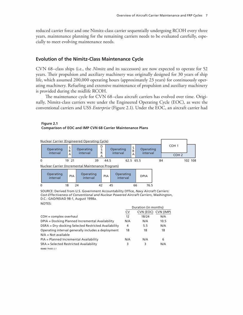
The maintenance cycle for CVN 68–class aircraft carriers has evolved over time. Origi-nally, Nimitz-class carriers were under the Engineered Operating Cycle (EOC), as were the conventional carriers and USS Enterprise (Figure 2.1). Under the EOC, an aircraft carrier had
Figure 2.1Comparison of EOC and IMP CVN 68 Carrier Maintenance Plans
SOURCE: Derived from U.S. Government Accountability Office, Navy Aircraft Carriers:Cost-Effectiveness of Conventional and Nuclear Powered Aircraft Carriers, Washington,D.C.: GAO/NSIAD 98-1, August 1998a.
Overview of Aircraft Carrier Maintenance and FRP Cycles 7
an 18-month operating interval, six months of which were on deployment (months 1 through 18)a three-month Selected Restricted Availability, or SRA (months 19 to 21)an operating interval (months 22 through 39)a 5.5-month docking SRA (months 40 through 44.5)an operating interval (months 44.5 through 62.5)a three-month SRA (months 62.5 through 65.5)an operating interval (months 65.5 through 83.5)a complex overhaul (months 83.5 through 101.5).
Following the first complex overhaul (COH 1), the above cycle would repeat, until the ship had a second, 28-month COH.
In essence, under the EOC, the aircraft carrier underwent a COH every seven to eight years. Meeting this schedule caused several problems. In particular, the concentration of work during the COHs caused large budget spikes. The EOC’s duration also led to challenges in workforce scheduling to handle both the COHs and other scheduled-maintenance availabili-ties, increasing the risk of late completion for the work.
To address these problems, in 1994 the Navy instituted the Incremental Maintenance Plan (IMP) for Nimitz-class carriers. Specifically, under the IMP, a carrier has
an 18-month operating interval (months 1 through 18)a six-month Planned Incremental Availabilities, or PIA (months 19 through 24)an 18-month operating interval (months 25 through 42)a six-month PIA (months 43 through 48)an 18-month operating interval (months 49 through 66)a 10.5-month Docking Planned Incremental Availability, or DPIA (months 67 through 76.5), for which the carrier is in the dry dock the first 7.5 months.5 The remaining time is spent at the depot facility.
At the end of the initial IMP cycles, CVN 68–class ships undergo a 36-month-long RCOH.6
Under both the EOC and the IMP, there are 12 operating intervals before and after the midlife RCOH.7 In contrast to the EOC, the IMP permits work to be funded and accomplished in more-even increments, thereby reducing the traditional COH budget spikes that occurred under the EOC, avoiding the increased amount of deferred maintenance that occurred just before the COHs, resulting in steadier and less-volatile shipyard workloads, and helping main-tain better overall ship conditions.
5 Since Kitty Hawk and Enterprise are of older classes, they remain under different maintenance cycles. Maintenance periods for the Kitty Hawk are shorter but more frequent than those for ships based in the United States. Enterprise remains under the EOC. The maintenance cycle for the new CVN 78 class has not yet been defined, but current analysis suggests a 48-month maintenance cycle between depot-level maintenance periods.6 Per Department of the Navy (2005c).7 Department of the Navy (2005c, p. 14).
1.
2.3.4.5.6.7.8.
1.2.3.4.5.6.
8 A Methodology for Estimating the Effect of Aircraft Carrier Operational Cycles
The Navy developed a CVN 68–Class Maintenance Plan, or IMP Sequencing Plan, to enhance and ensure the material readiness of the ships throughout their service life. The IMP Sequencing Plan identifies the equipment and systems to be tested, inspected, repaired, or otherwise serviced during each PIA or DPIA. The IMP Sequencing Plan is hull-specific, tracks maintenance requirements, and provides a basis for work plans and budgeting for availabilities.
Introduction of the Fleet Response Plan
In 2003, the Navy implemented the FRP to maximize its readiness and ability to respond to emergent crises. The FRP has meant formal changes for the way ships are to be trained and operationally available. Whereas the IMP featured 24-month cycles for operations, mainte-nance, and training, the FRP mandated a 27-month cycle. The notional8 aircraft carrier train-ing and readiness 27-month cycle, illustrated in Figure 2.2, includes phases for
maintenance/basic training (months 1 through 7) integrated training (months 8 through 12) sustainment (employability)/predeployment (months 13 through 18) deployment (months 19 through 24)sustainment /postdeployment (months 25 through 27).
We discuss each of these phases below. Note that, although the 27-month cycle as depicted in Figure 2.2 begins with a maintenance period rather than an operating interval, it is other-wise similar to the 24-month cycle of operating interval and PIA shown for the IMP in Figure 2.1. In fact, the FRP largely recognizes operating and maintenance cycles that had evolved in IMP practice. Both before and after implementation of the FRP, time between depot-maintenance availabilities was averaging 27 months.
Maintenance/Basic Training
The maintenance/basic training phase normally occurs after the postdeployment sustainment phase, when an aircraft carrier enters depot availability. In this phase, the aircraft carrier is unavailable for deployment.
Both during and following the depot availability, operational training is conducted for the ship’s crew both onboard and ashore at training commands. The goal of this training is to ensure that the crew is ready to support equipment testing and qualification for under-way watch stations. During the depot-level-maintenance period, the ship must balance the need and demand for maintenance to be performed by the ship’s force with schoolhouse and operational-training requirements.
8 The amount of time that an aircraft carrier is in a phase may vary, depending on the carrier.
•••••
Overview of Aircraft Carrier Maintenance and FRP Cycles 9
Figure 2.2Notional IMP 27-Month Cycle of Maintenance, Training, and Readiness
Advanced/Training Phase
Sustainment
Maintain C2 (JTFEX) Deploy13 14 15
Postdeployment25 26 27
16 17 18 19 20 21 22 23 24
Maintenance/Basic Training Phase Integrated Training Phase
Maintenance/Unit Level Training Gain C2 (includes C2X)1 2 3 4 5 6 7 8 9 10 11 12
Surge readyCan deploy in 15 days on avg. (30 max)
Routine deployable
Emergency surge readyCan deploy in 45 days on avg. (90 max)
RAND TR480-2.2
SOURCE: Derived from Department of the Navy, Aircraft Carrier Training and Readiness Manual,COMNAVAIRFORINST 3500.20A, March 10, 2005b.NOTE: At the initial stage of our research, the Navy used terms such as Emergency Surge, Surge Ready, and Routine Deployable to describe a CSG’s readiness to deploy. While we use these same terms in our discussion below, we also note new terms and definitions are now used to reflect changes in training and missions that can be undertaken. The term Global War on Terror (GWOT) Surge has replaced Emergency Surge, Major Combat Operations (MCO) Surge Ready replaces Surge Ready, and MCO Ready replaces Routine Deployable. These new terms and definitions standardize what CSG assets are expected to accomplish at each phase of readiness.
To allow the crew to meet training requirements, basic training consists of both in-port and underway training periods.9 The underway portion of the training is a 25-day period with the air wing embarked. Upon satisfactory completion of this training period, the ship is con-sidered available to deploy if necessary, in approximately 90 days.
After the basic training phase, the ship begins the integrated training phase. At that time, it becomes an operational asset that can be used by an operational commander, within limits and risks based on the extent of training achieved. The risks that could be encountered relate to missions assigned as opposed to the limits of the training received.
Integrated Training
The aircraft carrier begins integrated training after completion of basic training. The goal of the integrated phase is to bring together the individual units to allow strike group–level inte-
9 Tailored ship training availabilities (TSTAs) are constructed to focus on a ship’s training deficiencies, with the goal of training the crew to operating proficiency and increasing the crew’s training team’s ability to self-train.
10 A Methodology for Estimating the Effect of Aircraft Carrier Operational Cycles
grated training and operations in a challenging operational environment, as what is anticipated to be encountered during deployed operations. It provides an opportunity for units and staffs to complete CSG Commander Staff Planning and Warfare Commanders Courses, to conduct multi-unit in-port and at-sea training, and to build on individual skill proficiencies attained in earlier training.10 The carrier remains in the integrated training phase for approximately three months. During this time, the crew is undergoing training to perform the primary assigned naval wartime mission areas, achieving a C-2 or better overall status category, which indicates its readiness to perform the wartime mission for which it is organized.
The integrated phase includes a Combined Training Unit Exercise (COMPTUEX). The COMPTUEX is an 18-day exercise conducted by the Training Carrier Strike Group Com-mander. It focuses on developing the carrier and air wing into a cohesive unit and integrates other units into the CSG. The COMPTUEX culminates with a three-day final battle prob-lem designed to stress the CSG staff, carrier/air wing, and CSG units across all warfare areas. Throughout the integrated training phase, the aircraft carrier is expected to maintain a C-2 overall readiness status. The carrier achieves MCO Surge Ready status at the completion of the COMPTUEX, and it is ready for deployed operations.
Sustainment (Employability)/Predeployment
Sustainment training exercises units and staffs in multi-mission planning and execution, includ-ing the ability to interoperate effectively in a wartime environment. Once a unit or a CSG attains the required readiness levels for forward-deployed operations, key proficiencies required to carry out anticipated tasks must be maintained through tailored predeployment sustain-ment training approved by the numbered fleet commander (2nd or 3rd Fleet).11 Predeployment sustainment training is marked by the completion of a Joint Task Force Exercise (JTFEX). A JTFEX is nominally a 21-day underway period to exercise a CSG staff and units to integrate all assets to accomplish missions in a multithreat, multidimensional environment.12 The training events conducted during a JTFEX include mission-essential tasks that elements of the CSG are anticipated to perform during deployment. Under a notional schedule, once the CSG has completed a JTFEX, it is MCO-Ready (which is the goal for all deploying CSGs), sustains the MCO-Ready status and deploys for a six-month operating interval. Following this deploy-ment, it returns to its home port.
Under the FRP, upon return from deployment, an aircraft carrier not immedi-ately going into depot maintenance would be expected to sustain MCO-Ready status. Carriers returning from deployment are at their highest status of readiness and training. Post-deployment sustainment training may be necessary to maintain or sustain crew proficiency for
10 Department of the Navy (2005b, pp. 3–10).11 Department of the Navy (2005b, pp. 3–10).12 Fleet Training authorities indicate that a JTFEX has been done in port via a Fleet Synthetic Training (FST) Exercise. A FST Exercise utilizes shore-based command and control facilities to conduct warfare proficiency, operational, mission rehearsal, and joint interoperability training. It uses shore and ship-embedded simulation systems. Currently, only an East Coast ship has performed a JTFEX via FST in port.
Overview of Aircraft Carrier Maintenance and FRP Cycles 11
possible missions before the carrier enters maintenance. The training required would depend on crew turnover or length of time the ship is anticipated to remain Surge Ready.
Prioritizing Aircraft Carriers for Surge
The Fleet Response Plan calls for six aircraft carriers to be ready to deploy within 30 days, with an additional carrier ready for deployment within 90 days. Aircraft carriers that are not deployed are usually in different stages of readiness to deploy. In practice, if a 6 + 1 response were needed, the priority of the response would be provided by aircraft carriers that are
already deployedscheduled to deploy nextin the post-deployment sustainment phasein an Maritime Security Surge status.
The FRP Formalized Some Existing Practices
The FRP formalized a 27-month cycle of maintenance, training, and readiness that had already evolved in practice. Figure 2.3 represents the average elapsed time of Nimitz-class car-riers between the start of one depot availability and the start of the next (excluding lengthier RCOHs). For all eight carriers depicted, the average time between depot availabilities has
Figure 2.3Historical Average Number of Months Between Start of Nimitz-Class Depot Availabilities
0
5
10
15
20
25
30
35
Ave
rag
e n
um
ber
of
mo
nth
s b
etw
een
d
epo
t-le
vel a
vaila
bili
ties
CVN68
CVN69
CVN70
CVN71
CVN72
CVN73
CVN74
CVN75
NOTE: Because CVN 76 was commissioned in only July 2003, we exclude it from this figure.RAND TR480-2.3
••••
12 A Methodology for Estimating the Effect of Aircraft Carrier Operational Cycles
exceeded 24 months (indicated by the bottom dashed line on the figure). For three of the eight, the average time depicted has even exceeded 27 months (indicated by the top dashed line on the figure).
The FRP did not shorten the notional timeframes for performing aircraft carrier mainte-nance. PIAs remain six months long, and DPIAs remain 10.5 months long. The FRP also didnot alter the schedules for existing major repair and maintenance requirements; for upgrading weapons, communications, and engineering systems; or for nuclear refueling.13 That is, carrier maintenance and modernization continued as before the FRP was instituted.
What Is the Benefit of the FRP?
FRP increases availability and response by coordinating the maintenance and training readi-ness levels of all elements of the CSG. The FRP promotes readiness and response for individual aircraft carrier crews. The 6 + 1 CSGs that it provides are a formidable foe to any adversary. As the CNO states, the
FRP is mission-driven, capabilities-based, and provides the right readiness at the right time (within fiscal constraints). It enables responsive and dependable forward presence. With FRP we can deploy a more agile, flexible and scalable naval force capable of surging quickly to deal with unexpected threats, humanitarian disasters, and contingency operations.14
What Is New Under the FRP?
The FRP also instills a new mind-set of readiness that differs from traditional rotation pro-cesses by making a carrier available to surge within three to four months after its maintenance is completed.15 By contrast, the focus of traditional processes of maintenance, training, and staffing was on making the carrier ready for its next scheduled deployment in about one year after its maintenance period. By completing integrated training within six months after main-tenance availability, the ship achieves a higher state of readiness sooner and sustains it longer.
Next, we describe continuous-maintenance periods and how they may extend readiness both before and after deployment.
13 U.S. Government Accountability Office, Defense Logistics: GAO’s Observations on Maintenance Aspects of the Navy’s Fleet Response Plan, Washington, D.C., GAO-04-724R, June 18, 2004.14 U.S. Navy, Chief of Naval Operations, Statement of Admiral Michael G. Mullen, Chief of Naval Operations, Before the Senate Armed Services Committee, March 9, 2006.15 U.S. Government Accountability Office, technical corrections (GAO Code 350466) for Defense Logistics: GAO’s Obser-vations on Maintenance Aspects of the Navy’s Fleet Response Plan, GAO-04-724R, June 18, 2004.
Overview of Aircraft Carrier Maintenance and FRP Cycles 13
Continuous Maintenance
The formal implementation of continuous maintenance is a result of direction that NAVSEA gave in 2004 to its program office responsible for design, construction, and maintenance of aircraft carriers to evaluate a further extension of time between depot availabilities from 27 to 32 months. The evaluation concluded that there were no technical impediments to extending the time between depot availabilities to 32 months.16 In fact, the current depot maintenance schedule that NAVSEA provided to RAND researchers is for a 32-month schedule.17 (The 32-month cycle would eliminate four PIAs and two DPIAs over the life of the ship compared to the 24-month cycle, given that the time between depot maintenance can be extended.) As intervals between depot availabilities increase, work packages for the remaining PIAs and DPIAs will grow unless CM availabilities performed between the depot-level availabilities help alleviate PIA and DPIA workloads. Currently, the details of the content and duration of CM work packages are being evaluated and determined by fleet maintenance authorities.
Formally, the Joint Fleet Maintenance Manual18 defines CM as “a process that involves the near continuous flow of maintenance candidates to the most appropriate level and main-tenance activity for accomplishment.” Increasing the readiness of ships to surge as needed requires efficiently performing maintenance requirements and using all available windows of opportunity to fulfill those requirements. The Navy intends to provide needed depot main-tenance more frequently during scheduled, shorter-duration periods at a carrier’s home port, instead of deferring that maintenance until the normal six-month maintenance period arrives. Intensification of the CM process constitutes the essential core of the Fleet Response Plan’s maintenance component.19
Aircraft carriers are maintenance-intensive. Maintenance is constantly being performed on aircraft carriers (as well as other ships of the fleet). Hence, CM in itself is not a new concept. A ship’s force routinely performs preventive and corrective maintenance. In addition, while a ship is at home port (and even while a carrier is under way), shipyards routinely have personnel on the aircraft carrier performing maintenance.20 The formal implementation of CM is neces-sary to extend the operating and maintenance cycle from 27 to 32 months and to ensure that shipyard workload capacity is not exceeded during PIAs or DPIAs.
16 M. A. Gomori, “USS Nimitz (CVN 68) Class Aircraft Carrier 32-Month Maintenance Cycle Notional Analysis,” letter to Program Executive Officer, Aircraft Carriers, Newport News, Va., April 23, 2006.17 More precisely, this schedule defines a cycle in which the end of the next depot availability is 32 months from the end of the last such availability. Department of the Navy (2005c) similarly defines the cycle from the end of one depot availability to the end of the next. 18 Department of the Navy, Joint Fleet Maintenance Manual, Washington, D.C., Commander Fleet Forces Command Instruction 4790.3, Revision A, Change 6. 19 U.S. GAO (2004a).20 For example, Norfolk Naval Shipyard representatives indicated that they use about 100 workers per day at the Naval Station, performing routine upkeep work on an aircraft carrier.
14 A Methodology for Estimating the Effect of Aircraft Carrier Operational Cycles
Why CM Is Gaining in Importance
The FRP requires carriers that are not in basic training or maintenance periods to be able to get under way within 30 days of an order to deploy. Maintenance authorities have indicated that this readiness requirement conflicts with the need to perform needed maintenance.
One challenge posed by this requirement is that time is needed to test equipment after maintenance is complete. This testing period is fixed and, given time constraints, reduces the “wrench-turning” time for other repairs and adjustments.
Furthermore, maintenance must be integrated. Although some maintenance require-ments can be done in parallel, others cannot. Maintenance demands must be balanced with FRP surge readiness. An MCO Ready carrier is required to get under way within 30 days, for example, and cannot have maintenance performed that will take more than 30 days or less21 to complete (unless a waiver is obtained from operational authorities).
CM periods are not intended to affect surge readiness; instead, they enable more-traditional depot-level work to be performed while the aircraft carrier is located at the naval station rather than at its depot-level facility.22 For example, the Norfolk Naval Station is not a depot-level facility, but it is near the Norfolk Naval Shipyard (NNSY). Similarly, the Bremer-ton Naval Station is not a depot-level facility, but it is near the Puget Sound Naval Shipyard and Intermediate Maintenance Facility (PSNS & IMF). NNSY and PSNS & IMF workers can travel to the nearby naval stations to perform CM, although doing so causes some loss of productivity.
How Will CM Periods Be Conducted?
As operational cycles are extended, CMs will be used to meet life-cycle maintenance require-ments. Budgeting, scheduling, and execution planning for CM availabilities will usually occur up to one year in advance. The final work-execution planning will occur within two months of a scheduled CM period. Because CM packages will be large, advanced planning will be needed to address resource allocation for long-lead-time supply issues.
CM will be used to perform depot-level maintenance between the increased elapsed time between PIAs and DPIAs and will help carriers maintain their material condition and surge readiness. The ship’s Commanding Officer, Chief Engineer, and maintenance authorities will work with the shipyard maintenance authorities to determine the appropriate work packages to be completed, depending on the ship’s prioritized needs, time available, and operational avail-ability requirements.
What Can and Cannot Be Done During a CM Availability?
We met with NAVSEA authorities to discuss the limitations on what can be performed during a CM period. We specifically discussed the need for maintenance on the nuclear propulsion plant because it may be a major driver of maintenance demands, how it has been performed
21 Operational response and pre-(surge)deployment training demands may dictate that the timeline to get under way may be less than 30 days. 22 North Island Naval Station is a unique facility in that it is a depot-level facility and a home port for USS Ronald Reaganand USS Nimitz.
Overview of Aircraft Carrier Maintenance and FRP Cycles 15
in the past, and what may change in the future. Much of the work on the nuclear propulsion plant occurs at the shipyard. As depot maintenance intervals are extended, CM requires that some depot-level propulsion maintenance tasks be performed outside a depot.
Whereas the period between maintenance intervals may be extended, the number of notional man-days allotted to nuclear propulsion plant maintenance cannot change. There is some flexibility in performing nuclear maintenance requirements; and, as long as the mainte-nance man-days are not reduced, the timing of maintenance requirements may be adjusted. NNSY officials indicated that the maximum number of man-days that can be performed in a 30-day CM period is 24,000. PSNS & IMF authorities indicated that 10,000 to 15,000 man-days could be performed during a 30-day CM availability, and 30,000 to 35,000 in a 60-day availability. Maintenance authorities also told us that they supported a flexible approach that would allow nuclear maintenance work to be done in CMs when the shipyard has a supply of workers available.
In the past, nuclear maintenance was often performed at the expense of (or in place of) nonnuclear work also scheduled for depot availabilities. It occurred for a number of reasons, including the prioritization of work, availability of shipyard resources to perform the work, and limited funds for work packages. Shifting planned nuclear maintenance and modernization packages to CM periods can assist in reducing these conflicts. NAVSEA has evaluated nuclear maintenance requirements and identified what can be done during a CM availability. These work packages will not require setting specific nuclear plant conditions (i.e., they will focus on tasks that do not require plant shutdown or cooldown) or time-consuming integrated testing.
The changes we have discussed in this section have implications for the ability of the maintenance industrial base, the naval shipyards that service carriers, to perform the neces-sary maintenance requirements while meeting FRP (6 + 1) carrier surge-readiness demands. In particular, they affect both the average number of operationally available carriers and demands on the workforce at the shipyards that support carrier maintenance. Analytic tools and meth-odologies are needed to help in understanding these effects. We next turn to the development and use of such tools.
16 A Methodology for Estimating the Effect of Aircraft Carrier Operational Cycles
17
CHAPTER THREE
Modeling the Maintenance Industrial Base
In the preceding chapter, we described how the FRP formalized a maintenance cycle that was already in use and that had evolved over time. As a result, FRP itself had little or no effect on the industrial base. In fact, cycle lengths were increased from 24 to 27 months without sup-porting maintenance analysis being performed, because this change represented only what had evolved in practice.
Other changes, as noted, are being implemented or considered that would also affect the operational availability of aircraft carriers and would place new and different demands on the maintenance industrial base. In this chapter, we describe an approach for assessing the effect of these changes on the industrial base and the industrial base’s ability to meet these new demands.
The Aircraft Carrier Maintenance Industrial Base
The shipyards that make up the aircraft carrier maintenance industrial base include1
Norfolk Navy Shipyard (NNSY) Northrop Grumman Newport News (NGNN) Puget Sound Naval Shipyard and Intermediate Maintenance Facility (PSNS & IMF).
NNSY supports all Atlantic Fleet aircraft carriers, and it also provides depot-level support to submarines and large-deck amphibious ships. In addition to performing carrier availabilities at the shipyard, NNSY routinely sends maintenance personnel to Norfolk Naval Station to provide support for the carriers based there. As noted in the preceding chapter, sending ship-yard workers to the operating bases reduces their productivity because of the extra commuting and setup time required, as well as the occasional unavailability at the station of needed tools,
1 Pearl Harbor Naval Shipyard provides some limited depot-level support to carriers stopping there while deployed in the Pacific theater. It is not a home port to any carrier; hence, it is not considered to be part of the carrier maintenance industrial base. Maintenance is performed on San Diego–based carriers at Naval Air Station, the North Island depot maintenance facility that is managed by PSNS & IMF.
•••
parts, or test equipment. As a result, NNSY planners include a 25-percent inefficiency penalty2
when sending workers to the operating base. NGNN provides all depot-level support for USS Enterprise and conducts all RCOHs
for Nimitz-class carriers. PIAs and DPIAs are also assigned to NGNN when there are facility or workforce constraints at NNSY. NGNN is the only shipyard capable of building nuclear aircraft carriers. It typically has two carriers under construction at any one time. NGNN also performs post-shakedown3 availabilities (PSAs) for newly constructed carriers. In addition to its carrier work, NGNN, with General Dynamics Electric Boat, constructs Virginia-class submarines.
PSNS & IMF supports West Coast carriers based at Bremerton (USS John C. Stennis), Everett (USS Abraham Lincoln), and San Diego (USS Nimitz and USS Ronald Reagan). It sends workers to all three locations.
Because Bremerton is adjacent to the shipyard, there is little loss in productivity when PSNS workers support the carrier at the operating base. Everett is not collocated, and PSNS & IMF workers must commute to perform maintenance there. The resulting loss in productivity is similar to that incurred by NNSY when sending workers to the Norfolk Naval Station.
San Diego–based ships are supported by a depot maintenance facility on North Island Naval Air Station (NAS). This facility is managed by PSNS & IMF, and PSNS & IMF main-tainers conduct all nuclear-related maintenance on the San Diego–based carriers. PSNS & IMF workers fly to San Diego to perform maintenance, and PSNS & IMF has found this arrangement to be very efficient. The maintainers are provided travel and per diem and are focused on completing repairs and returning home. NGNN manages the non-nuclear-related work for carriers based there, subcontracting with several Master Ship Repair contractors to accomplish the work.
PSNS & IMF will also support USS George Washington when it shifts home port to Japan. PSNS & IMF will send workers for temporary duty to Japan to perform nuclear-related maintenance. Local shipyards in Yokosuka, Japan, will perform nonnuclear maintenance as they currently do on USS Kitty Hawk. As PSNS & IMF workers travel to Yokosuka, NNSY will begin to send maintainers to San Diego to mitigate the increased load on PSNS & IMF from USS George Washington.
2 The challenges of performing work at the naval station (instead of at the shipyard) and the resulting inefficiency penalty were described by NNSY workload planners to the research team during meetings at the Carrier Planning Activity, a divi-sion of NAVSEA responsible for the aircraft carrier maintenance plan. 3 Shakedown refers to the performance of sea trials to evaluate the performance of ship systems at sea. A PSA provides a dedicated opportunity to correct deficiencies and/or emergent repairs from the sea trial and shakedown period.
18 A Methodology for Estimating the Effect of Aircraft Carrier Operational Cycles
Modeling Workload Demand and Workforce Supply
To understand the workforce implications of different maintenance cycles at the shipyards that make up the maintenance industrial base, we modified a RAND model that was initially used to analyze changes in ship-acquisition programs.4
The model first estimates the workload demand at the trade-skill level (welders, electri-cians, etc.) over time at each of the shipyards. (We list the trade skills in the public shipyards in Table 3.1 later in this chapter.) It includes workload demands resulting from maintenance, modernization, decommissioning, and other projects for the various ship classes supported by a shipyard. The model uses shipyard-provided future workforce supply at the shipyards and compares supply to demands to understand how the workforce must be adjusted to accomplish the desired workload.
Private-sector corporations that build naval ships have more flexibility than do public-sector shipyards to adjust their workforce to demand. The private shipyards can terminate workers, at a cost, when supply exceeds demand, and they can hire new workers, again at a cost in dollars and proficiency levels, when demands rise.
As noted, the public shipyards cannot adjust their permanent workforce as rapidly as can the private sector. These yards have permanent workers whose employment cannot be terminated with ease when the workload demand drops in a given period. Accordingly, they are reluctant to hire permanent workers to meet a sudden temporary surge in demand. As a result, the public shipyards typically maintain a core workforce of permanent workers and tap as necessary into the pool of local temporary workers or subcontractors, who can be hired and terminated according to the different terms of agreements in their contracts.
The public shipyards also use overtime to help meet workload demands. NNSY and PSNS & IMF can operate efficiently with up to 20-percent overtime, but inefficiencies result when overtime exceeds this level. Overtime can be performed through six-day workweeks or in two shifts, with a small contingent of workers performing nonnoise operations during a third shift.5
The four public shipyards (NNSY, PSNS & IMF, Portsmouth Naval Shipyard, and Pearl Harbor Naval Shipyard) and the two private shipyards (NGNN and General Dynamics Elec-tric Boat) that perform nuclear-related work also share workers under a plan called One Ship-yard.6 One Shipyard treats workers as if they were in one (virtual) shipyard, sending excess workers at one shipyard to augment the workforce at another shipyard when needed. PSNS & IMF authorities told us that they plan to send workers to NNSY to support availabili-ties for CVN 71 and CVN 73. Likewise, NNSY will send workers to San Diego for a PIA scheduled for CVN 76 in 2010, when PSNS & IMF workers will be in Japan for CVN 73 maintenance.
4 Mark V. Arena, John F. Schank, and Megan Abbott, The Shipbuilding and Force Structure Analysis Tool: A User’s Guide,Santa Monica, Calif.: RAND Corporation, MR-1743-NAVY, 2004.5 Work is not normally performed on aircraft carriers from 10 p.m. to 6 a.m. because the crew is living onboard.6 Appendix A provides more information on the One Shipyard concept.
Modeling the Maintenance Industrial Base 19
Trade Skills at the Public Shipyards
Examining the aggregate effects of maintenance on the shipyard workforce may mask more-significant effects for specific trade skills. Our model therefore considers supply and demand for different trade-skill groupings. The shipyards have more than 100 categories and subcat-egories of trade skills. For the purposes of modeling, we consolidated these groupings into nine major categories. Table 3.1 lists these broad categories and some examples of individual skill categories in each. Appendix B lists individual categories and subcategories of skills and the broad category in which we classify them.
Supply at the Public Shipyards
We obtained the supply data on the public-shipyard workforce from NNSY and PSNS & IMF. These Workload Allocation and Resource Report (WARR) data files show the monthly supply of workers available to perform maintenance, as well as supply-and-demand data projected for the next ten years.
The total workforce for PSNS & IMF is approximately 10,000 workers, 8,500 of whom are in Bremerton and 1,500 of whom are at the Intermediate Maintenance Facility in Bangor, Washington. NNSY has approximately 7,800 workers. At any given time, however, only about three-fifths of these workers will be on site at the shipyard. Workers may be absent because of leave, training, or other reasons. Some of these absences are cyclical; many workers, for exam-ple, take two-week vacations around Christmas and New Year’s. Figure 3.1 presents data on the anticipated actual number of available workers in each shipyard by month through 2015. Nearby subcontractors and temporary workers are also hired at both shipyards as needed.7
Table 3.1Trade-Skill Groupings Included in the Analysis
Trade-Skill Category Includes Trade Skills
Construction support Tool shop, boiler shop, insulators, transportation
Electrical Electronics
Engineering Nuclear and radiation skills, test engineer, planning/project engineer
NOTE: Although making up few individual categories, welders, pipe fitters, electrical, and structures workers are given their own category grouping because they deal with only a few different shops.
7 NNSY managers make their own decisions on hiring additional temporary help; however, at PSNS & IMF, the Type Commander decides what work private companies will perform. Such work is already scheduled for the private yards when the ship arrives for maintenance.
20 A Methodology for Estimating the Effect of Aircraft Carrier Operational Cycles
Figure 3.1Projected Available Workforce at NNSY and PSNS & IMF, 2006–2015
0
1,000
2,000
3,000
4,000
5,000
6,000
7,000W
ork
ers
Jun 06 Jun 07 Jun 08 Jun 09 Jun 10 Jun 11 Jun 12 Jun 13 Jun 14 Jun 15
Fiscal year
NNSY Available Force
PSNSY Available Force
RAND TR480-3.1
Available workers can be classified as two types: production labor and support labor. Pro-duction labor is labor that completes maintenance demands. Support labor is indirect labor and includes engineers, inspectors, and project managers. In Table 3.1, we further break down pro-duction labor into nine categories. We next develop a method to forecast workload demands.
Modeling Workload Demands at the Public Shipyards
Each shipyard in the analysis supports multiple classes of ships, including large-deck amphibi-ous ships, surface combatants, and submarines. Each shipyard also performs various depot maintenance–related tasks. For our model, we varied the cycle time and content of aircraft carrier depot work to be performed while keeping other work constant. That is, for modeling purposes, we used the current projected schedules for work on other classes of ships without allowing for those adjustments that shipyard managers might otherwise make to accommo-date possible changes in aircraft carrier maintenance schedules. This is, of course, an artificial constraint. In practice, workforce planners move and change workers to different ships (as well as reschedule ships to be maintained) to meet deadlines and balance workloads. Nevertheless, by holding other work constant, we were able to see how aircraft carrier work alone will affect the supply and demand of work at the shipyards.
Modeling the Maintenance Industrial Base 21
Below, we discuss the notional profile and work content by different trade skills for vari-ous repair availabilities. We also describe the noncarrier workloads we hold constant in our analysis. In the next chapter, we discuss carrier workload estimates under different mainte-nance cycles.
Phases of an Availability
Notionally, repair availabilities, such as PIAs, DPIAs, and CM periods, are only a matter of months and reflect when work is actually being done on a ship. From a shipyard point of view, the availability is much longer, encompassing the time from the start of planning to the end of testing and feedback for the availability. Budgeting and scheduling, advance planning, and execution planning phases, for example, are started at least 12 months before the beginning of the notional availability. At the other end, a feedback phase that is also part of shipyard work for the availability reports the actual completion of work so that the next cycle of work can be planned. Below, we discuss the full length of shipyard work—specifically, the demand for labor by skill, for PIAs, DPIAs, and CM periods for aircraft carriers, as well as for work on other vessels these shipyards support.
Planned Incremental Availability (PIA)
As previously noted, PIAs have a notional duration of six months, which represents the time that the ship is actually in the shipyard. Nevertheless, PIAs also include a prior planning and prefabrication time, as well as a subsequent testing, assessment, and inspection time at the end of a depot availability. The planning/prefabrication period can extend to 12 months, and the testing, assessment, and inspection can vary based on the equipment in which maintenance was performed. Thus, from a shipyard-workload-planning perspective, the total length of a PIA is between 17 and 20 months.
Figure 3.2 provides a sample workload profile for a notional six-month PIA in a 27-month maintenance cycle. The notional PIA—i.e., the period when the ship is actually in the shipyard—runs from December 2006 to June 2007. Note, however, that workdays are required from every group of skilled workers we classified, both before and after this time, and some construction support workers are required to begin working on this PIA in February 2006.
The PIA profiles differ for 27-, 32-, and 36-month cycles. In particular, as noted in the preceding chapter, the more the interval increases between depot availabilities, the more a depot work package will increase, and the greater the number of man-days that each depot availability requires will be. Within each cycle, our model shows that the profiles of workdays needed by skill area for PIAs and DPIAs have similar shapes throughout the time period when the carrier is in the yard. DPIA profiles are very different from the PIA profile.
Docking Planned Incremental Availability (DPIA)
DPIAs are notionally planned for 10.5 months; however, because the smallest time step in our model is one month, for our analysis we assume that DPIAs are 11 months. DPIAs require a
22 A Methodology for Estimating the Effect of Aircraft Carrier Operational Cycles
Figure 3.2Notional PIA Profile, by Trade Skill
Construction supportElectricalEngineeringMachinistsOther supportOutfittingPipe fittingStructuresWelding
0
200
400
600
800
1,000
1,200
1,400
1,600
1,800M
an-d
ays
Jun07
May07
Apr07
Mar07
Feb07
Jan07
Dec06
Nov06
Oct06
Sep06
Aug06
Jul06
Jun06
May06
Apr06
Mar06
Feb06
Jul07
Planning/workup Ship in yard
WorkdownRAND TR480-3.2
dry-docking of the aircraft carrier for approximately 7.5 months. After 7.5 months, the dry-dock work is completed and the ship is moved to a depot pier to complete repair, maintenance, mod-ernization, and testing. The DPIA permits maintenance personnel to perform underwater hull inspections and other maintenance evaluations that cannot be accomplished while the carrier is waterborne.8 More time is also available during DPIAs to perform needed modernization.
As with PIAs, DPIAs also require a planning/prefabrication period and a work-testing period. Figure 3.3 provides a sample profile of work, by trade skill, for a notional DPIA. In this DPIA, the ship is actually in the shipyard from January to November 2007. Nevertheless, as with the PIA, workdays are required from every group of skilled workers both before and after this time, from August 2006 through December 2007.
Continuous-Maintenance Availability (CMA)
As noted earlier, CM is an evolving concept. A CM availability is planned depot-level work that occurs outside of the depot at the ship’s home port. More specifically, CMs occur when
8 Naval Sea Systems Command (NAVSEA), Aircraft Carrier Class Maintenance Plan, Washington, D.C., December 2005.
Modeling the Maintenance Industrial Base 23
Figure 3.3Notional DPIA Profile, by Trade Skill, for a 32-Month Cycle
Construction supportElectricalEngineeringMachinistsOtherOutfittingPipe fittingStructuresWelding
0
200
400
600
800
1,000
1,200
1,400
1,600
1,800W
ork
ers
Month
Dec 07
Nov 07
Oct 07
Sep 07
Aug 07
Jul 0
7
Jun 07
May
07
Apr 07
Mar
07
Feb 07
Jan 07
Dec 0
6
Nov 06
Oct 0
6
Sep 0
6
Aug 06
Jul 0
6
Jun 0
6
May
06
Jan 0
8
RAND TR480-3.3
an aircraft carrier is in a MCO Surge/Ready state while at home port, after its training and before its deployment. After an initial PIA, CMs would occur in between depot availabilities for ships on longer (e.g., 32- or 36-month) maintenance cycles. As we discuss in the next chap-ter, the exact timing of CMs would depend on the maintenance cycle for a ship.
Deferred work from, and new work that has arisen since, a previous availability can be performed in CM. A CM period will most likely last for 30 to 45 days. The work package for a CM period for each carrier will be based on its prioritized maintenance requirements, the time available for completion, availability of supplies, and other similar variables. For the purposes of our modeling, we assume that a CM work package has the same mix and ratio of trade skills as that of a PIA. That is, we assume that the proportional distribution of workdays by skill in the six-month PIA matches that of the 30–45-day CM, although the actual number of work-days by skill will obviously differ.
Noncarrier Work
In addition to their work on carriers, both NNSY and PSNS & IMF work on other naval ships. In fact, this other work makes up about two-thirds of the total work done at the two shipyards. Table 3.2 lists the ship classes constituting this “other” work.
24 A Methodology for Estimating the Effect of Aircraft Carrier Operational Cycles
Table 3.2Ship Classes Contributing to Noncarrier Work
Ship Class Class Type Shipyard
SSN 688 Attack Submarine Norfolk, Puget
SSBN 726 Ballistic Missile Sub Norfolk, Puget
SSGN 726 Guided-Missile Sub Norfolk, Puget
LHA 1 Amphibious Assault Norfolk
LHD 1 Amphibious Assault Norfolk
LPD 4 Amphibious Norfolk
LPD 17 Amphibious Norfolk
LSD 41 Amphibious Norfolk
LSD 49 Amphibious Norfolk
AS 39 Submarine Tender Norfolk, Puget
Figure 3.4 shows a sample workload profile for some of this work. Specifically, it depicts the distribution of workdays by skill groups for an engineered refueling overhaul (ERO) on an SSBN 726–class vessel. The ERO requires the same broad set of trade skills as the carrier depot availabilities, but the number and duration of those skills over the maintenance period vary.
Figure 3.4Notional Workload Profile of an SSBN Engineered Refueling Overhaul (ERO)
For our model, we used the supply of available workers from data that the shipyards provided. We modeled demand for workers by using NAVSEA maintenance schedules and ship-work-load profiles by availability. Current schedules for aircraft carrier maintenance reflect a 32-month cycle—i.e., a 32-month duration from the end of one depot availability to the end of the next depot availability. From the current schedules and the supply and demand for workers, we evaluated where the supply of workers exceeds demand or demand exceeds supply.
For our modeling purposes, the workload for ships other than aircraft carriers is assumed to be fixed and independent of all the options considered for the carriers in the analysis. All the work done on noncarriers is shown in the gray areas of the workload plots in the next chapter. This “other work” is depicted in Appendix C.
Given a “constant” workload for other ships, we can examine the effects of varying the cycle lengths for carrier maintenance on overall shipyard workload. We turn to the effects of varying aircraft carrier maintenance schedules on the maintenance industrial base in the next chapter.
26 A Methodology for Estimating the Effect of Aircraft Carrier Operational Cycles
27
CHAPTER FOUR
Development and Analysis of Alternative Maintenance Strategies
In Chapters One and Two, we outlined the future maintenance demands of CONUS-based Nimitz-class aircraft carriers and a model for assessing the effects of these demands on the industrial base. In this chapter, we examine how three different notional maintenance cycles—the 27-month cycle of the FRP, the 32-month cycle toward which these ships have been evolv-ing, and a 36-month cycle—will affect workloads at the public shipyards that perform the vast majority of Nimitz-class maintenance.1
We describe how we applied the notional 27-, 32-, and 36-month cycles to the aircraft carrier fleet to develop unconstrained maintenance schedules. We next review the logic used to resolve facility-scheduling problems to produce our workload schedules for analysis. We then discuss the effect on various measures of operational availability of the different carrier maintenance schedules. Finally, we provide the workload demand and supply profiles under the various options and show the results of the analyses.
Developing Notional Maintenance Schedules
Developing projected maintenance schedules required collecting and evaluating a large amount of data. Initially, we used a Gantt chart from the Carrier Planning Activity of NAVSEA, which displayed the maintenance schedules for the carrier fleet through 2012. This chart was based on a 27-month depot maintenance cycle. We extended the patterns from this chart and devel-oped a 20-year maintenance schedule for the Nimitz-class carriers. Again, we assumed that other work would not vary in response to shifting carrier work schedules, which allowed us to examine the effect of the increased aircraft carrier intervals on the maintenance industrial base.
NNSY provided a maintenance schedule through 2015, which included all ships and reflected a 27-month cycle for the carriers. The actual schedule from NNSY closely matched the notional 27-month schedule that we developed using the CPA Gantt chart. NAVSEA 04, whose responsibility includes Logistics, Maintenance, and Industrial Operations, then pro-
1 RCOH work is excluded from this analysis, as are PIAs performed at NAS North Island for aircraft carriers based there. Although we do not directly include NGNN in the analysis, we do examine the potential for NGNN and NNSY to interact (or share workers) during periods when one or both shipyards have challenges of matching workforce supply with demand.
vided us with a maintenance schedule for all four shipyards, which included carriers on a 32-month cycle. We then used this 32-month cycle as our baseline and developed a 36-month- cycle schedule based on the NAVSEA-provided 32-month-cycle schedule.
NAVSEA 04 also supplied March 2006 maintenance schedules for the other ships that the public yards service. As noted, we assumed, for modeling simplicity, that these schedules would not change even if aircraft carrier maintenance cycles were to do so.
Aircraft Carrier Notional Cycles
Figure 4.1 shows the notional sequence of PIAs and DPIAs for 27-, 32-, and 36-month cycles for Nimitz-class carriers. Again, cycle length refers to the length of time from the end of one PIA to the end of the next PIA (excluding DPIAs). Note that, in contrast to earlier figures, this figure shows operating intervals (in light blue), PIAs, and DPIAs, and, for ships with a 32- or 36-month cycle, CM periods in years rather than months.
In addition to showing the timing of PIAs and DPIAs, the figure shows, for ships on a 32-month and 36-month cycle, notional placement of CM periods. It also shows, in subscripts, the type of PIA each ship will undergo. Although PIAs and DPIAs are, as noted earlier, largely similar within cycles, they are in fact not identical and do change slightly over time.
Figure 4.1Notional Cycles for Nimitz Class
Mo
nth
cyc
le
36
32
27 RCOH
RCOH
RCOH
24222018161412
Year
1086420 26
PIA2 PIA2PIA1 PIA1 PIA3
CM2 CM2 CM2CM1 CM1 CM1 CM3
CM2 CM2 CM2CM1 CM1 CM1 CM3 CM3
DPIA2 DPIA3
PIA2 PIA2PIA1 PIA1 PIA3PIA3DPIA2 DPIA3
PIA2 PIA2PIA1 PIA1 PIA3 PIA3PIA3DPIA1 DPIA2 DPIA3
RAND TR480-4.1
28 A Methodology for Estimating the Effect of Aircraft Carrier Operational Cycles
The figure shows that a carrier under the 32-month (PIA) cycle has an eight-year DPIA or dry-docking cycle, in contrast to the approximately six-year dry-docking cycle for ships under the 27-month maintenance cycle.
RCOHs are notionally planned to occur by the middle of the twenty-fifth year of a car-rier’s operation.2 These cycles assume the current operational tempo (OPTEMPO). RCOHs are condition-based (when the ship is out of energy), not time-based. To the extent that OPTEMPO changes within existing cycles or that different cycles generate additional opera-tional time utilized by the fleet, the cycles may have to be truncated to induct the ship into a RCOH sooner.
In view of the notional carrier schedules, a carrier on a 32-month cycle would be due for a DPIA at the end of its twenty-fourth year, at which time the carrier would enter RCOH rather than a DPIA, slightly truncating the RCOH cycle to a little less than 24 years. This truncation, coupled with the more significant extension of the PIA cycle, means a carrier on a 32-month cycle would have one less PIA and one less DPIA than a ship on the 27-month cycle. Similarly, the figure shows that a carrier under the 36-month (PIA) cycle has a nine-year dry-docking cycle and would enter RCOH rather than a third DPIA in its twenty-fourth year of operation. This results in two fewer PIAs and one less DPIA than a ship on a 27-month cycle.
We analyze the demands on shipyard workload for each of the PIA cycles—27-, 32-, and 36-month—depicted above. Because Nimitz-class ships were delivered at irregular intervals and because active ships are at different points in their operational and maintenance cycles, we made some assumptions in developing future workload schedules for 32- and 36-month cycles.
Specifically, we assumed that aircraft carriers that had completed a depot availability by the end of March 2006 would have its PIA cycle extended as necessary to the 32- or 36-month cycle scenarios we wished to consider. For other ships, we assumed that the next depot avail-ability would occur as then scheduled, after which its cycle would be extended as necessary to reflect the scenario under consideration. We also assumed that the USS Nimitz is on a 12-year docking cycle, with a 15-month DPIA beginning in FY2006.3
With one exception, we do not consider any facility constraints. The exception was iden-tifying and resolving competing demands for limited dry docks. We discuss below how we resolved these conflicts to develop realistic maintenance schedules for the 36-month-cycle scenario.
2 Nimitz-class aircraft carriers go through an RCOH near the midpoint of their approximate 50-year life cycle. During RCOHs, the carrier’s nuclear fuel is replenished and the ship’s services and infrastructure are upgraded to prepare for another 25 years or more of service. 3 The CNO has approved USS Nimitz for the 12-year docking. CPA has projected that the availability will be 15 months long. The reason for the change is an effort to further reduce maintenance costs and to determine whether the same approach can be adopted for the rest of the fleet.
Development and Analysis of Alternative Maintenance Strategies 29
Resolving Dry-Dock Conflicts
Only three active dry docks in the continental United States are capable of servicing a com-missioned, nuclear-powered carrier: one each at NNSY and NGNN on the East Coast and one on the West Coast at PSNS & IMF. Under the notional schedules we consider, there may be situations in which the East Coast and West Coast carriers have overlapping DPIAs and dry-dock needs.
We resolved these conflicts by shifting specific carrier availabilities up to three months from that suggested by the notional cycle in such guidelines as those set in OPNAV Notice 4700 for cycles of 36 months or less. Each conflict was also resolved in such a way that the maximum number of Maritime Security Surge and MCO Surge/Ready carriers was yielded for the notional 27-, 32-, and 36-month cycles.
An additional dry-docking issue worth noting, although not one causing any conflicts in our notional schedules, is the pending extension of the dry dock at NNSY. CVN 76 and successive carriers have bulbous bows, lengthening the ships and resulting in the need for an extended dry dock. The dry-dock extension at NNSY will begin following an amphibious ship dry-docking concluding in March 2009, and must be completed prior to a DPIA for the USS Harry S. Truman beginning in January 2014. These constraints give NNSY nearly five years to complete the project. There are no planned dry-dockings at NNSY during this time, but removing one of the country’s three dry docks from service means that emergency dry-dock-ings cannot be performed there.
Workload Requirements for Notional Cycles
NNSY provided workload profiles for all the depot availabilities performed in the shipyard. These same profiles are used by PSNS & IMF. For each availability, we had data broken down by month and by the shipyard shop performing the work, providing us with the amount of work expected in any given month of availability. We use the breakdown of the shops to cor-respond to trade skills, as discussed in Chapter Three. Each of the notional workload pro-files uses the workload from the OPNAV Notice 4700 (Department of the Navy, 2005c). Extending the maintenance-cycle length from 27 to 32 or 36 months results in different depot-availability workloads.
The CPA, which provides research and analytic support to NAVSEA and is responsible for the aircraft carrier maintenance plan, developed a set of workloads for this analysis based on its Incremental Maintenance Plan (IMP) for the CVN 68 class. CPA engineers used the original IMP as a basis for new availability packages, examining the IMP line by line to develop new PIAs and DPIAs for the carriers.
Table 4.1 shows the notional man-days allotted (per OPNAV Notice 4700) for each depot-level maintenance availability for the Nimitz-class carriers under the 27-month cycle.
30 A Methodology for Estimating the Effect of Aircraft Carrier Operational Cycles
Table 4.1Workload Requirements for Carriers (27-Month Cycle)
Additionally, CPA provided the estimates for modernization man-days (also called Program Alterations) that need to be included for each carrier.
The CPA determined that some efficiencies could be gained when the maintenance cycle was extended beyond 27 months. Across the lifetime of Nimitz carriers, around 500,000 man-days could be eliminated by moving from a 27-month to a 32-month cycle. Most of this reduc-tion resulted primarily from elimination of event-based maintenance (such as docking work) and maintenance support (project management, test support, work control, etc.) needed for the eliminated availabilities. The CPA analysis led to a reduction in the total number of man-days by determining whether each maintenance requirement in the IMP could be moved to the next availability or must be completed in an earlier one. The same analysis was assumed by CPA to be applicable for a 36-month cycle.4
As noted earlier, the 32- and 36-month cycles result in one fewer DPIA over each half of the carrier’s operational life. CPA assumed that the first docking after both carrier delivery and the midlife RCOH would require more man-days than would the first docking in a 27-month cycle. CPA uses the man-days allotted to a DPIA2 for the first docking and DPIA3 for the second docking in each half of the carrier’s life. The CPA evaluation of a 32-month cycle with an eight-year docking for the Nimitz class also includes CM periods.5
These changes result in the man-day requirements depicted in Table 4.2. The require-ments for the three PIA work packages are the same, but recall also that the 36-month cycle would require one fewer PIA before and after RCOH. This reduction leads to an increased requirement in maintenance days through performance of CM availabilities for carriers on
Table 4.2Availability Workloads (in thousands of man-days) Based on CPA Analysis (includes modernization)
4 We discussed the applicability of the 32-month depot cycle with CPA planners. They indicated that the 32-month depot workload could also be used for the 36-month workload. In practice, there is flexibility in scheduling depot maintenance periods ±3 months from the notional schedule.5 NAVSEA, Carrier Planning Activity, 32-Month Operational Cycle Analysis, draft report, February 28, 2006.
Development and Analysis of Alternative Maintenance Strategies 31
this schedule. Carriers on both the 32- and 36-month cycles6 would also not have a DPIA1package, although they would have slightly larger DPIA2 and DPIA3 packages, as well as CM that would not be performed on ships on the 27-month maintenance cycle.
Modeling NNSY
We next examine the workload demands and supply at each shipyard for different aircraft-carrier depot-level cycle lengths. We begin with the 27-, 32-, and 36-month profiles for NNSY, then show the same scenarios for PSNS & IMF.
Figure 4.2 shows the demand profile at NNSY under a 27-month cycle for the carriers it services. The supply of available workers, as reported in the WARR data, is indicated by the black-and-white curve. The short drop in supply each year at NNSY is associated, as noted ear-lier, with the reduced manning of the shipyard over the Christmas holidays. We note that some availabilities overlap, and we indicate the overlapping availabilities by labels. For example, con-secutive PIA3s occur during the period June 06 to February 08, and the two PIA3 labels denote
Figure 4.2NNSY 27-Month Cycle
Other Work
DPIA1
DPIA2
PIA San Diego
PIA1
PIA2
PIA3
Avail Force
0
2,000
4,000
6,000
8,000
10,000
12,000
Wo
rker
s
Period
Jun 14
Oct 13
Feb 13
Jun 12
Oct 11
Feb 11
Jun 10
Oct 0
9
Feb 0
9
Jun 0
8
Oct 07
Feb 07
Jun 0
6
Feb 15
Oct 15
RAND TR480-4.2
PIA3
PIA3
PIA3
PIA2PIA2
PIA2
DPIA2
DPIA2
PIA3
6 We assume the same total man-days for a 32-month cycle and a 36-month cycle.
32 A Methodology for Estimating the Effect of Aircraft Carrier Operational Cycles
that two availabilities occur during this period. We use this labeling construct consistently throughout this figure and the figures that follow.
In each figure, the shaded gray area indicates all other demand on the shipyard. Recall that, in order to identify the specific effect of demand for aircraft carrier maintenance on each shipyard, we assumed this other demand would remain constant across scenarios or not be adjusted to reflect different carrier maintenance cycles. Shadings above this gray area reflect the extra demand caused by differing maintenance depot-level availabilities for each carrier. For example, the far-left portion of the above figure indicates that, in late 2006 and early 2007, in addition to the demand placed on it by all other ships, NNSY must also handle demand placed on it by concluding work for a DPIA1 package for a CVN as well as for early work on a PIA3package for another CVN. NNSY manages excess demand by working shipyard personnel at 10 to 15 percent overtime (or more depending on demand),7 outsourcing work to private con-tractors, and utilizing temporary workers, as discussed further in Chapter Five.
Under the 27-month cycle, there would be no notional depot-level availabilities in which a carrier is actually in the yard in 2010, although some preliminary work on a PIA1 package for a CVN would occur. Carrier demands on the shipyard will also decrease under all cycles we consider with the transfer of the USS George Washington to Yokosuka, Japan, to replace the Kitty Hawk as the forward-deployed carrier in 2008. Other demands on the shipyard will also be low from 2008 through 2010 as the midlife refuelings of Los Angeles-class submarines conclude.
As a result, the supply of workers at this shipyard under the 27-month cycle will actually exceed demand for several months. Demands on the workforce would increase in later years as the USS George H. W. Bush (CVN 77) approaches its first depot-level availabilities, the Eisenhower (CVN 69) requires a DPIA2 package, and new attack submarines continue to be introduced.
Figure 4.3 shows the demand profile at NNSY under a 32-month depot-level mainte-nance cycle for carriers. Again, demands by other ships on the yard are assumed not to vary from current projections, and hence appear in the same gray shading as in Figure 4.2.
Here, also, no depot-level availabilities are scheduled in the yard in 2010. A CM period is scheduled for CVN 77 at this time. In addition, the PIA for CVN 76—which, as we noted earlier, NNSY workers would support in San Diego—would occur later, as would the PIA2package for CVN 69, reducing some of the excess of workforce supply over demand during this time. Later occurrence of all other carrier maintenance, including the DPIA2 package for CVN 75 and the PIA1 package for CVN 77, would also lead to a higher notional peak demand on the yard than is evident in the 27-month cycle.
7 NNSY can work shipyard personnel up to approximately 25-percent overtime for up to one month to meet peak demands. After one month’s time, personnel fatigue and other factors yield diminishing returns on productivity.
Development and Analysis of Alternative Maintenance Strategies 33
Figure 4.3NNSY 32-Month Cycle
DPIA1DPIA2PIA San Diego
PIA1PIA2PIA3
CM 1CM 2CM 3 Other Work
Avail Force
0
2,000
4,000
6,000
8,000
10,000
12,000W
ork
ers
Period
Jun 12
Dec 11
Jun 11
Dec 10
Jun 10
Dec 0
9
Jun 0
9
Dec 0
8
Jun 0
8
Dec 07
Jun 07
Dec 0
6
Jun 0
6
Dec 12
Jun 13
Jun 14
Dec 13
Dec 14
Jun 15
RAND TR480-4.3
PIA3
PIA2
PIA2
PIA2
DPIA2
DPIA2
PIA2
PIA3
Figure 4.4 shows the demand profile at NNSY under a 36-month depot-level-mainte-nance cycle for the carriers. Here, there are no notional depot-level availabilities or even work preparing for or concluding such availabilities, in 2009 and 2010. Also, no notional PIAs or DPIAs are occurring from the end of 2012 to the middle of 2014, although some CM peri-ods are scheduled. As a result, notional workload demand drops below supply briefly in 2013 before far outstripping supply later in 2014.
34 A Methodology for Estimating the Effect of Aircraft Carrier Operational Cycles
Figure 4.4NNSY 36-Month Cycle
DPIA1DPIA2PIA San Diego
PIA1PIA2PIA3
CM 1CM 2CM 3 Other Work
Avail Force
0
2,000
4,000
6,000
8,000
10,000
12,000W
ork
ers
Period
Jun 12
Dec 11
Jun 11
Dec 10
Jun 10
Dec 0
9
Jun 0
9
Dec 0
8
Jun 0
8
Dec 07
Jun 07
Dec 0
6
Jun 0
6
Dec 12
Jun 13
Jun 14
Dec 13
Dec 14
Jun 15
RAND TR480-4.4
PIA3PIA2
PIA2
PIA2
DPIA2
DPIA2
PIA2
PIA3
Modeling PSNS & IMF
PSNS & IMF will experience a decrease in workload from 2008 through 2010 as submarine-related work decreases. Beyond that, PSNS & IMF has several periods in which the projected supply of workers is expected to exceed demand.
Figure 4.5 shows the demand profile at PSNS & IMF under a 27-month cycle for the carriers it services. Under this cycle, the shipyard would have a particularly difficult period in 2011, when a DPIA, two PIAs, and support of an SRA for the Washington, CVN 73, are all scheduled to occur. Demand would fall below supply in late 2011 and much of 2012, as well as in 2014, but would reach its second-highest peak in 2015. Unlike in NNSY, only in one brief period in 2008 would demand caused by the other ships that PSNS & IMF services exceed the projected workforce availability.
Development and Analysis of Alternative Maintenance Strategies 35
Figure 4.5PSNS & IMF 27-Month Cycle
0
2,000
4,000
6,000
8,000
10,000
12,000W
ork
ers
Period
Jun 12
Dec 11
Jun 11
Dec 10
Jun 10
Dec 0
9
Jun 0
9
Dec 0
8
Jun 0
8
Dec 07
Jun 07
Dec 0
6
Jun 0
6
Dec 12
Jun 13
Jun 14
Dec 13
Dec 14
Jun 15
RAND TR480-4.5
PIA San DiegoDPIA 3DPIA2PIA2
PIA3SRA CVN YOKO DPIA1
Other WorkAvail Force
Figure 4.6 shows the demand profile at PSNS & IMF under a 32-month cycle for the carriers it services. This cycle appears to reduce the duration and magnitude of the oversup-ply periods. Whereas demand for workers at PSNS & IMF would peak above 10,000 under the 27-month cycle, peak demand remains below 9,000 under the 32-month cycle. The peak would occur in 2012, when a DPIA1 package for CVN 76, a PIA2 package for CVN 70, a CM3 package for CVN 72, and preliminary work for a DPIA2 package for CVN 74 would all be under way concurrently.
36 A Methodology for Estimating the Effect of Aircraft Carrier Operational Cycles
Figure 4.6PSNS & IMF 32-Month Cycle
0
2,000
4,000
6,000
8,000
10,000
12,000W
ork
ers
Period
Jun 12
Dec 11
Jun 11
Dec 10
Jun 10
Dec 0
9
Jun 0
9
Dec 0
8
Jun 0
8
Dec 07
Jun 07
Dec 0
6
Jun 0
6
Dec 12
Jun 13
Jun 14
Dec 13
Dec 14
Jun 15
RAND TR480-4.6
DPIA2DPIA3PIA San Diego
PIA2PIA3SRA CVN YOKO
CM 1CM 2CM 3
Other WorkDPIA1
Available Force
CM
CM
PIA San Diego
PIA San DiegoPIA San Diego
PIA San Diego
Figure 4.7 shows the projected demand profile at PSNS & IMF under a 36-month cycle for the carriers it services. Lengthening the cycle appears to reduce again the very high peak demand associated with the 27-month cycle. Nevertheless, the overall demand profile appears to be more uneven than that occurring under the 32-month cycle, with slightly higher peaks and more times when workforce supply exceeds demand.
Development and Analysis of Alternative Maintenance Strategies 37
Figure 4.7PSNS & IMF 36-Month Cycle
0
2,000
4,000
6,000
8,000
10,000
12,000W
ork
ers
Period
Jun 12
Dec 11
Jun 11
Dec 10
Jun 10
Dec 0
9
Jun 0
9
Dec 0
8
Jun 0
8
Dec 07
Jun 07
Dec 0
6
Jun 0
6
Dec 12
Jun 13
Jun 14
Dec 13
Dec 14
Jun 15
RAND TR480-4.7
CM3
CM3
PIA2PIA2
DPIA3PIA San DiegoPIA2PIA3
SRA CVN YOKOCM 1CM 2CM 3
Other WorkDPIA1DPIA2
Avail Force
Fixed Lifetime Maintenance Option
Given the uncertainty in the workload content of the PIAs and DPIAs under longer cycles, we also considered options in which the total maintenance workload over the life of an aircraft carrier was fixed and independent of the length of the cycle.8 That is, we summed the total maintenance and repair man-days for the PIAs and DPIAs under the 27-month schedule, and distributed this higher total of man-days across the PIAs and DPIAs in both the 32- and 36-month schedules for a FLM case.9 Table 4.3 shows the man-days that would constitute each PIA, DPIA, and CM package under the FLM case for the 32- and 36-month cycle scenarios, as well as under the baseline 27-month cycle.
8 This workload option approximates constant depot-level funding for carrier maintenance over the life of a carrier.9 The modernization man-days are assumed to be constant and independent of the increase in time between availabilities. This assumption may or may not be true.
38 A Methodology for Estimating the Effect of Aircraft Carrier Operational Cycles
Table 4.3Availability Workloads: FLM Case (thousands of man-days)
Figure 4.8 shows how the FLM case affects demand at NNSY under a 32-month cycle for the carriers it services. Under this scenario, notional demand peaks in 2014 at over 10,000 workers—compared with less than 5,000 available—and also exceeds 8,000 briefly in 2007 and 2008.
Figure 4.9 shows how the FLM case affects demand at NNSY under a 36-month cycle for the carriers it services. Under this scenario, peak demand exceeds 8,000 workers several times throughout the next decade, including most of 2014 and 2015.
Figure 4.8NNSY 32-Month Cycle: FLM Case
DPIA1DPIA2PIA San Diego
PIA1PIA2PIA3
CM 1CM 2CM 3 Other Work
Available Force
0
2,000
4,000
6,000
8,000
10,000
12,000
Wo
rker
s
Period
Jun 12
Dec 11
Jun 11
Dec 10
Jun 10
Dec 0
9
Jun 0
9
Dec 0
8
Jun 0
8
Dec 07
Jun 07
Dec 0
6
Jun 0
6
Dec 12
Jun 13
Jun 14
Dec 13
Dec 14
Jun 15
RAND TR480-4.8
PIA2 PIA2DPIA
DPIA
PIA2
PIA2
Development and Analysis of Alternative Maintenance Strategies 39
Figure 4.9NNSY 36-Month Cycle: FLM Case
DPIA1DPIA2PIA San Diego
PIA1PIA2PIA3
CM 1CM 2CM 3 Other Work
Avail Force
0
2,000
4,000
6,000
8,000
10,000
12,000W
ork
ers
Period
Jun 12
Dec 11
Jun 11
Dec 10
Jun 10
Dec 0
9
Jun 0
9
Dec 0
8
Jun 0
8
Dec 07
Jun 07
Dec 0
6
Jun 0
6
Dec 12
Jun 13
Jun 14
Dec 13
Dec 14
Jun 15
RAND TR480-4.9
PIA3 PIA2
PIA2
PIADPIA2
DPIA2
PIA2
PIA3
Figure 4.10 shows how the FLM case affects demand at PSNS & IMF under a 32-month cycle for the carriers it services. Under this scenario, peak demand exceeds 10,000 workers—compared to a projected available supply of about 6,000—in 2012 and is above 8,000 several other times as well.
40 A Methodology for Estimating the Effect of Aircraft Carrier Operational Cycles
Figure 4.10PSNS & IMF 32-Month Cycle: FLM Case
0
2,000
4,000
6,000
8,000
10,000
12,000W
ork
ers
Period
Jun 12
Dec 11
Jun 11
Dec 10
Jun 10
Dec 0
9
Jun 0
9
Dec 0
8
Jun 0
8
Dec 07
Jun 07
Dec 0
6
Jun 0
6
Dec 12
Jun 13
Jun 14
Dec 13
Dec 14
Jun 15
RAND TR480-4.10
DPIA2DPIA3PIA San Diego
PIA2PIA3SRA CVN YOKO
CM 1CM 2CM 3
Other WorkDPIA1
Available Force
CM3
CM3
PIA San Diego
PIA San Diego
CM3
CM3
Figure 4.11 shows how the FLM case affects demand at PSNS & IMF under a 36-month cycle for the carriers it services. Under this scenario, peak demand nearly reaches 10,000 work-ers in 2012 and exceeds 8,000 workers several other times. Yet demand also falls short of supply several times, including 2010 and much of 2012 and 2013.
Development and Analysis of Alternative Maintenance Strategies 41
Figure 4.11PSNS & IMF 36-Month Cycle: FLM Case
0
2,000
4,000
6,000
8,000
10,000
12,000W
ork
ers
Period
Jun 12
Dec 11
Jun 11
Dec 10
Jun 10
Dec 0
9
Jun 0
9
Dec 0
8
Jun 0
8
Dec 07
Jun 07
Dec 0
6
Jun 0
6
Dec 12
Jun 13
Jun 14
Dec 13
Dec 14
Jun 15
RAND TR480-4.11
DPIA2DPIA3PIA San Diego
PIA2PIA3SRA CVN YOKO
CM 1CM 2CM 3
Other WorkDPIA1
Available Force
CM3
CM3
PIA2
PIA2
Under all the FLM scenarios depicted above, the demand for shipyard workers exceeds supply by 50 percent or more several times over the next decade. The shipyards may not be able to manage such spikes in demand. The ability of the shipyards to meet these larger workload packages, especially when carrier availabilities overlap, is highly problematic.
Challenges with Workforce Management
During our interviews with shipyard maintenance authorities, they indicated that there are limitations in planning and scheduling their workforce to meet maintenance demands:
Because of space limitations onboard the carrier, having more than 1,500 workers on a carrier on any given day causes inefficiencies in accomplishing the work. The shipyards typically use overtime to meet increased demands, and overtime can aver-age 10 to 20 percent of the total hours expended during availability. Higher levels of overtime for a sustained period (greater than a month) can result in worker fatigue, inef-ficiencies, and mistakes.
•
•
42 A Methodology for Estimating the Effect of Aircraft Carrier Operational Cycles
As mentioned earlier in this chapter, shipyard planners note overall constraints on work-ers they could support. Specifically, they are not sure they can support more than 18,000 man-hours during a 30-day CM period.Continuous-maintenance availability (CMA) periods should not overlap depot carrier availabilities or other CMAs, except to balance the workload to the workforce available within the same shipyard.
In the next chapter, we review more generally how the demand of differing scenarios matches the projected supply of likely workers, including which scenarios might result in the most even distribution of demand.
•
•
Development and Analysis of Alternative Maintenance Strategies 43
45
CHAPTER FIVE
Effects on the Industrial Base
One can draw broad inferences from the plots of supply and demand in Chapter Four, but it is difficult to directly compare the effect of one cycle to that of another over an extended period. We develop several measures that compare supply and demand at the shipyards. We do this at both NNSY and PSNS & IMF for each of five scenarios we examined in the tables in Chapter Four, including the scenarios for 27-, 32-, and 36-month carrier maintenance cycles based on CPA data and the 32- and 36-month cycles based on the Fixed Lifetime Maintenance assumptions.
Norfolk Naval Shipyard
Table 5.1 illustrates various summary measures of supply versus demand for each cycle and case examined for NNSY. It shows the average number of workers per month when demand exceeds supply, as well as when supply exceeds demand, for the five cases analyzed. The columns are organized for times when demand is greater than supply and when supply is greater than demand. Total workload refers to the aggregate number of man-days for each case; number of months means how many months the event occurred; and the average per month is the total workload under each category divided by the number of months. For example, in the “Total Workload” column, we subtracted the supply from the demand (in workers) for each month
Table 5.1NNSY: Supply Versus Demand Measures for Different Cycles (totals and averages in thousands of workers)
Case
Demand Greater Than Supply Supply Greater Than Demand
Total Workload
Number of Months
Average per Month
Total Workload
Number of Months
Average per Month
27-month 194.3 104 1.9 2.7 8 .3
32 CPA 187.8 106 1.8 1.4 6 .2
36 CPA 181.9 96 1.9 7.9 16 .5
32 FLM 227.7 106 2.1 1.2 6 .2
36 FLM 242.9 97 2.5 7.2 15 .5
in which demand was greater than supply, and summed those values for each case listed. For example, for the 27-month option, there was a total of 194,300 man-days in 104 months, averaging 1,900 man-days per month when workload demand was greater than supply. There were 2,700 man-days in eight months, averaging 300 man-days per month when the supply of workers was greater than the demand.
In the aggregate, the demand for labor at NNSY is consistently greater than the supply of labor. There are some months when the available workforce supply exceeds demand, but by small margins. For example, the table shows that the highest average by which supply exceeds demand is about 500 workers, for 16 months under both the basic and FLM plans for main-taining carriers on a 36-month cycle. By contrast, when demand exceeds supply, we found that it would do so by an average of at least 1,800 workers. From this perspective, the FLM options under both the 32- and 36-month cycles appear to have the most severe situations in which demand exceeds supply. Under the FLM option for the 32-month cycle, there are 106 months in which demand exceeds supply and in which, on average, an additional 2,100 workers are needed to meet demand. Under the FLM option for the 36-month cycle, there are 97 months in which demand exceeds supply, in which, on average, an additional 2,500 workers—or more than half the workers that we earlier saw are likely to be available—are needed to meet demand.
Overall, shipyard planners prefer to have demand exceed supply, but by no more than an average of 10 percent. Within this limit, shipyard planners can both ensure that their work-ers are fully employed and allow for some overtime, and still retain some flexibility in moving them under the One Shipyard concept.
To assess the matching of supply and demand under the five options over time, we plot-ted, in Figure 5.1, a frequency distribution of the total number of months for each case in which supply exceeds demand (left side) or demand exceeds supply (right side). The horizontal axis shows a range in which supply exceeds demand or demand exceeds supply, while the verti-cal axis shows the number of months for each condition on the horizontal axis. At the far left, for example, the figure shows that there are no months, under any scenario we examine, in which the supply of workers exceeds the demand for them by more than 40 percent, whereas there are a few months, under the base and FLM 36-month scenarios, in which the supply exceeds demand by at least 20 percent.
Ideally, all the curves shown above would peak between the two vertical bars, showing where supply exceeds demand or demand exceeds supply by no more than 10 percent. This sit-uation would mean that workload over the next decade would be most concentrated in months in which shipyard resources are fully used and in which overtime, when it is necessary, would not reach unsustainable levels at which inefficiencies result from worker fatigue.
None of the curves of projected workload at NNSY, including that derived from the 27-month cycle baseline, peak in this ideal range; in fact, all peak to the right of it or in months in which more than 10 percent overtime may be required. Still, there are some differences worth noting. For example, the projected workload under the 32-month cycle scenario developed
46 A Methodology for Estimating the Effect of Aircraft Carrier Operational Cycles
Figure 5.1Distribution of Months by Scenario at NNSY in Matching Supply of and Demand for Workers
0
5
10
15
20
25
30
91–1
00%
81–9
0%
71–8
0%
61–7
0%
51–6
0%
41–5
0%
31–4
0%
21–3
0%
11–2
0%
0–10%
0–10%
11–2
0%
21–3
0%
31–4
0%
41–5
0%
51–6
0%
61–7
0%
71–8
0%
81–9
0%
91–1
00%
Nu
mb
er o
f m
on
ths
Supply > Demand Demand > Supply
27-month cycle baseline 32-month, CPA analysis with CM
36-month, CPA analysis with CM32-month, FLM analysis with CM 36-month, FLM analysis with CM
RAND TR480-5.1
Frequency when supply>demand by 11% or more
Frequency when demand>supply by 11% or more
with CPA data (and not the FLM option) appears to have more months concentrated more closely to the ideal range than the 27-month baseline scenario. (Conversely, under the 36-month FLM option, there would be more months in which workload demand is nearly double supply than any other type of month.)
We also evaluated supply and demand for representative trade skills at NNSY to deter-mine whether a critical shortage of trade skills occurs during the 36-month cycle. Our analysis of the electrical, pipe fitting, structures, and welding trade skills generally follows the pattern of the aggregate supply and demand for the cycle. The analysis shows that, overall, supply exceeds demand, but an oversupply occurs during the 2009–2010 period. The results of this analysis are in Appendix D.
Can NGNN Help NNSY?
We also considered whether Northrop Grumman Newport News could help alleviate some of the problems caused by uneven workload at the Norfolk Naval Shipyard—specifically, that of slack demand in 2010. Located close to each other, NNSY and NGNN share a special relation-ship. As noted earlier, NNSY workers perform all nuclear carrier work on the East Coast, and NGNN is the only nuclear-carrier builder in the United States. NGNN performs all CVN refueling and all depot-level availabilities performed on the USS Enterprise. As the need arises, NGNN and NNSY can share workers under the One Shipyard concept. NGNN has per-
Effects on the Industrial Base 47
formed availabilities that NNSY did not have the time or workforce to perform. NGNN also routinely supplies workers to NNSY when requested to do so.
Figure 5.2 shows notional projected workloads by type at NGNN through 2015, includ-ing those for decommissioning the Enterprise (CVN 65 Inactivation), its Extended Selected Restricted Availability (CVN 65 ESRA), and its Extended Dry-docking Selected Restricted Availability (CVN 6 EDSRA). (Because these data are proprietary, exact values are not given on the vertical axis.)
Puget Sound Naval Shipyard
Table 5.2 shows various summary measures of workforce supply versus demand for each cycle for PSNS & IMF. As for NNSY, the aggregate demand for labor is consistently greater than the supply of labor. Nevertheless, the excess of demand over supply is not as great at PSNS & IMF as at NNSY. For example, in the table, the highest average by which demand exceeds supply at PSNS & IMF is 1,600 workers, during the 79 months under the 36-month cycle for FLM. By contrast, the average excess demand by scenario for the NNSY as shown in Table 5.1 is 1,800 workers or higher.
Figure 5.2NGNN Workload with CVN 65 Availabilities
Jun 06 Jun 07 Jun 08 Jun 09 Jun 10 Jun 11 Jun 12 Jun 13 Jun 14 Jun 15
48 A Methodology for Estimating the Effect of Aircraft Carrier Operational Cycles
Table 5.2PSNS & IMF: Supply Versus Demand Measures for Different Cycles(totals and averages in thousands of workers)
Case
Demand Greater Than Supply Demand Less Than Supply
Total Workload Number of
MonthsAverage per
Month Total WorkloadNumber of
MonthsAverage per
Month
27-month 106 82 1.3 20 30 .7
32 CPA 89 82 1.1 17 30 .6
36 CPA 71 71 1.0 29 41 .7
32 FLM 130 87 1.5 14 25 .6
36 FLM 122 79 1.6 26 33 .8
At the other extreme, the months with an excess of supply over demand at PSNS & IMF appear to be somewhat more pronounced than those at NNSY. For each of the five scenarios we examine in Tables 5.1 and 5.2, there are more months at PSNS & IMF than at NNSY in which workforce supply exceeds demand. The average excess during these times is also higher at PSNS & IMF than at NNSY.
To assess options for PSNS & IMF over time, we plotted, in Figure 5.3, a frequency distribution of the total number of months for each case in which supply exceeds demand or demand exceeds supply. Again, ideally, the curves for each scenario would peak in the range, shown by the two vertical bars in the middle of the graph, in which neither supply nor demand exceeds the other by 10 percent.
Figure 5.3Distribution of Months, by Scenario, at PSNS & IMF in Matching Supply of and Demand for Workers
0
5
10
15
20
25
30
91–1
00%
81–9
0%
71–8
0%
61–7
0%
51–6
0%
41–5
0%
31–4
0%
21–3
0%
11–2
0%
0–10%
0–10%
11–2
0%
21–3
0%
31–4
0%
41–5
0%
51–6
0%
61–7
0%
71–8
0%
81–9
0%
91–1
00%
Nu
mb
er o
f m
on
ths
Supply > Demand Demand > Supply
27-month cycle baseline 32-month, CPA analysis with CM
36-month, CPA analysis with CM32-month, FLM analysis with CM 36-month, FLM analysis with CM
RAND TR480-5.3
Frequency when supply>demand by 11% or more
Frequency when demand>supply by 11% or more
Effects on the Industrial Base 49
Each scenario we examined for PSNS & IMF shows the distribution overlapping more of the ideal range than those for NNSY. But, again, none peaks within this ideal range. Never-theless, all the curves here are more concentrated toward the ideal range than are those for the NNSY scenarios. Overall, as at NNSY, the scenario for the 32-month cycle based on CPA data appears to offer the most months in which supply most closely matches demand, with relatively few months in which supply exceeds demand or demand far exceeds supply.
In sum, for both NNSY and PSNS & IMF, the 32-month CPA analysis with CM periods leads to lower fluctuations in the workload when matched against the manpower resources. This option has three further specific advantages worth noting:
First, it would eliminate the very large spike in work that would occur under the 27-month cycle in 2011 at PSNS & IMF, as shown in Figure 4.5, when more than 10,000 workers would be needed to service four different carriers then scheduled for maintenance. Second, it would smooth some of the “peaks” and “valleys” shown in Figures 4.10 and 4.11 for workload at PSNS & IMF. Third, by eliminating a DPIA for CVN 68, the 32-month cycle would avoid irresolvable dock conflicts.
Ultimately, of course, maintenance schedules must make carriers available to the Navy. In the next chapter, we examine the effects of the 27-, 32-, and 36-month options on operational availability measures for the aircraft carrier fleet.
•
•
•
50 A Methodology for Estimating the Effect of Aircraft Carrier Operational Cycles
51
CHAPTER SIX
Effects on Operational Availability
Operationally, a carrier may be in one of four states:
in maintenanceundergoing basic training phasein Maritime Security Surge (MSS), MCO Ready or MCO Surge statusdeployed.
Aircraft carriers that are in maintenance are not deployable; those in basic training phase are deployable within 90 days; and, upon completion of basic phase training, carriers can be deployed within 30 days.
Extending the carrier maintenance cycle from 24 to 27 months introduces a trade-off between having a ship be deployed for its own operations and having it deployable as needed to surge. Before the FRP, the 24-month IMP notional cycle included six months for PIA mainte-nance and 10.5 months for DPIA maintenance, followed by a training period, and then a six-month deployment. The readiness level of a carrier decreased during the maintenance period and then gradually increased during training to achieve deployable status just before going on deployment. The 27-month FRP cycle maintained the six-month deployment while achieving deployable status more quickly and sustaining that status for longer periods.
Two net results of extending the maintenance cycle are worth noting here. First, moving from a 24- to a 27-month cycle decreases the proportion of time that a carrier is deployed per cycle (assuming one six-month deployment per cycle), from 25 percent (6 months out of 24) to 22 percent (6 months out of 27). Second, increasing the cycle length increases the propor-tion of time that a carrier is available to deploy. Thus, extending the cycle increases operational availability and surge readiness; but, if the aircraft carrier performs only one deployment per cycle, the percentage of time deployed and in forward presence decreases.1
In this chapter, we examine how 27-, 32-, and 36-month maintenance cycles would affect the number of carriers in maintenance, deployable, or deployed in coming years.
1 This change was in line with the former CNO’s “presence with a purpose” policy, which stipulated that ships will be consistently maintained in a high state of readiness and deploy when there is a need to deploy (instead of in a routine deployment).
••••
Aircraft Carriers in Maintenance
Figure 6.1 shows our model results of the average number of carriers in maintenance (i.e., in a PIA, DPIA, or RCOH) from FY2006 through FY2024 for the 27-, 32-, and 36-month car-rier maintenance cycles. The 27-month baseline case is indicated in the solid shading; differing curves indicate the results for the 32- and 36-month cycles.
The average number of carriers in maintenance at any one time over this period decreases as cycle length increases, from 3.63 for the 27-month cycle to 3.16 for the 36-month cycle. There is little difference in the 32- and 36-month cycle averages, but moving from the 27-month cycle to the longer cycles results in a decrease of approximately 10 percent in the average number of carriers at the depots. For the 32- and 36-month cycles after 2010, the minimum average number of carriers in maintenance is slightly lower, and the maximum average number of carriers in maintenance is slightly higher, than those for the 27-month cycle.
The drop in the averages for all three cycles in 2010 results from the gap between the end of the operational life of the USS Enterprise and the operational availability of the first CVN 78–class carrier. The trend line for the 36-month cycle is erratic, especially between 2011 and 2017.
In sum, increasing carrier maintenance-cycle length can reduce the number of carriers in maintenance and make more carriers available to deploy or surge. However, implementing
Figure 6.1Number of Carriers in Maintenance for Various Cycles
27-month32-month36-month
RAND TR480-6.1
0
2005
2006
2007
2008
2009
2010
2011
2012
2013
2014
2015
2016
2017
2018
2019
2020
2021
2022
2023
2024
Fiscal year
1
2
3
4
5
6
Car
rier
s in
mai
nte
nan
ce
Average number Cycle of carriers over length 20 years 27-month 3.63 32-month 3.25 36-month 3.16
52 A Methodology for Estimating the Effect of Aircraft Carrier Operational Cycles
longer cycles must be timed carefully to prevent problems in managing the workforce of the maintenance industrial base.
Deployable Carriers
We next examine the number of aircraft carriers that can be deployed or surged under varying maintenance cycles for the FRP. Among factors that we assumed could limit the ability of a carrier to surge are
six-month PIAs, 10.5-month DPIAs, or 36-month RCOHs, in which a carrier is not available for deployment one-month weapons offloading before a PIA, DPIA, or RCOHbasic training length of three months following a PIA, five months following a DPIA, seven months following RCOH, and nine months following new construction.2
Figure 6.2 shows our model results of the number of deployable carriers—i.e., carriers that are Maritime Security Surge, MCO Surge/Ready, or deployed—for the various main-tenance cycles and with the above restrictions. The Forward Deployed Naval Force (FDNF) aircraft carrier is included in our analysis.3 Since longer maintenance cycles result in CVNs spending less time in maintenance availabilities, they have more time available to the fleet for operation. Therefore, the average number of deployable carriers increases as maintenance-cycle length increases.
The period between the retirement of the Enterprise in 2013 and the commissioning of CVN 78 in 2015 is a particularly challenging time. In 2013 and 2014, fewer than six deploy-able carriers are available under either the 27- or 32-month cycles. In 2015, none of the sce-narios we examine would provide an average of six deployable carriers throughout the year.
Table 6.1 presents a different perspective on the figure, showing the proportion of time in coming years that the Navy can deploy a given number of carriers, assuming one deployment per cycle. For example, the top-left cell shows that, under a 27-month cycle, the Navy could deploy at least eight carriers 13.8 percent of the time.
As expected, the probability of having a given number of carriers available to meet an operational demand increases as the cycle length increases. Nevertheless, (under our assump-tions) even with the 36-month cycle, the Navy can surge 6 + 1 carriers only 57 percent of the time; with a 27-month or 32-month cycle, it can meet this operational goal less than half the time. The continuous presence of at least one Nimitz-class carrier in an RCOH also makes it difficult to meet surge requirements throughout this period. Extending the cycle contributes to greater surge ability, but still other measures may have to be taken to achieve greater avail-ability of the carrier fleet.
2 Crew turnover during longer depot-level periods requires additional time for unit-level training.3 The Forward Deployed Naval Force carrier is not counted as deployed while in a maintenance period.
•
••
Effects on Operational Availability 53
Figure 6.2Number of Deployable Carriers for Various Cycles
27-month32-month36-month
RAND TR480-6.2
0
2005
2006
2007
2008
2009
2010
2011
2012
2013
2014
2015
2016
2017
2018
2019
2020
2021
2022
2023
2024
Fiscal year
1
3
5
7
9
2
4
6
8
10D
eplo
yab
le c
arri
ers
Average number Cycle of carriers over length 20 years 27-month 5.89 32-month 6.34 36-month 6.67
Table 6.1Deployable Carriers (percentage) as a Function of Cycle Length
Carriers 27-Month 32-Month 36-Month
≥8 13.8% 18.3% 28.8%
≥7 32.1% 40.8% 56.7%
≥6 60.0% 76.3% 79.6%
≥5 86.7% 92.5% 92.9%
Deployed Carriers
As noted earlier in this chapter, there is a trade-off between deployable and deployed carriers. Longer cycle times make carriers deployable for greater lengths of time, but the six-month limit on deployments and the limit of one planned deployment between depot-level availabilities also mean that they reduce the number of deployed carriers.4
4 These cycles generate more operating time for use by the fleet. The cycles assume the current operational tempo. To the extent that operational tempo changes within existing cycles or that different cycles generate additional operation time used by the fleet, the cycles may have to be truncated to induct the ship into an RCOH sooner.
54 A Methodology for Estimating the Effect of Aircraft Carrier Operational Cycles
Figure 6.3 presents the average number of deployed carriers by fiscal year for each carrier maintenance cycle we considered. Our model results in significant periods of time in which only one carrier would be deployed. (In fact, under the scenario for the 36-month cycle, the “average” number of deployed carriers for 2009 would be less than one.) The 27- and 32-month cycles would allow the Navy to maintain an average of at least two deployed carriers across the time we examine, whereas the scenario for the 36-month cycle would have an average of less than two deployed carriers.
We summarize Figures 6.1 through 6.3 in Figure 6.4 below. Assuming one deploy-ment per cycle, over the 20-year period from FY2005 through FY2024, the average number of aircraft carriers in maintenance and in training decreases as cycle length increases. The number of Surge Ready carriers increases as cycle length increases. Our modeling indicates that the number of deployed carriers decreases as cycle length increases. As noted at the beginning of this chapter, there is a trade-off between deployable and deployed carriers. Longer cycle times make carriers deployable for greater lengths of time, but we constrained our modeling to a six-month limit on deployments and to one planned deployment between depot-level availabili-ties. We realize that, in practice, aircraft carriers could, and most likely would, be deployed to a greater extent. The increased average number of Surge Ready carriers with increased cycle length enables an increase in CVNs that can be surged.
Figure 6.3Average Number of Carriers Deployed for Various Cycles
RAND TR480-6.3
0
2005
2006
2007
2008
2009
2010
2011
2012
2013
2014
2015
2016
2017
2018
2019
2020
2021
2022
2023
2024
Fiscal year
0.5
1
1.5
2
3
2.5
3.5
Car
rier
dep
loym
ents
Average number Cycle of carriers over length 20 years 27-month 2.37 32-month 2.13 36-month 1.95
27-month32-month36-month
Effects on Operational Availability 55
Figure 6.4Summary of Operational States of U.S. Aircraft Carriers for 27-Month, 32-Month, and 36-Month Cycles
RAND TR480-6.4
27-month 32-month 36-month
Cycle duration
0
2
4
6
8
10
12
Ave
rag
e n
um
ber
of
carr
iers
,b
y re
adin
ess
stat
e
3.63
1.48
3.52
2.37
3.25
1.41
4.21
2.13
3.16
1.17
4.72
1.95
MaintenanceTraining
Emergency surge/surgeDeployed
56 A Methodology for Estimating the Effect of Aircraft Carrier Operational Cycles
57
CHAPTER SEVEN
Summary and Concluding Observations
In this research effort, we develop a methodology to evaluate different cycle lengths and sizes of depot work packages, and estimate the effect on the maintenance industrial base as it relates to the supply of and demand for labor. We also estimate the effect of different cycle lengths on the operational availability of the aircraft carrier fleet and discuss trade-offs between work-package sizes, depot-maintenance duration, and operational availability.
We evaluate the 27-, 32-, and 36-month cycle length. We estimate the effect of the supply of and demand for labor against the aggregate depot man-days developed for the IMP (27-month cycle), CPA-developed work package for the 32-month cycle, and the fixed life main-tenance option that keeps the IMP 27-month man-days constant and distributes them over depot availabilities for the 32- and 36-month cycles. Our modeling capability uses four main inputs: the maintenance schedules of ships, the notional maintenance availability workload profiles for each ship class, the labor supply, and notional man-days per availability. The carrier maintenance schedules were used to determine the number of operationally available carriers to support the FRP 6 + 1 requirements—that is, providing six carriers in 30 days and an addi-tional carrier in 90 days.
Regarding the maintenance industrial base, we project an oversupply of labor in compari-son to demand under a 27-month cycle for carrier maintenance in 2010 for both NNSY and PSNS & IMF. This oversupply can be minimized under a 32-month cycle (with CM periods), should work profiles reflect those of the CPA analysis. This same option can also help minimize periods of excess demand and workload fluctuations in the next decade. Our modeling also indicates a period of decreased demand in the 2010 timeframe for the 36-month cycle. The 32-month cycle would also minimize inefficiencies resulting from loss of learning for subsequent availabilities, which are inherent in scenarios with still-longer cycles, such as the 36-month cycle.
For both NNSY and PSNS & IMF, the 32-month CPA analysis with CM periods leads to lower fluctuations in the workload when matched against the manpower resources.
Our results are sensitive to varying assumptions on workload. In part because longer maintenance cycles would mean fewer maintenance availabilities, we assumed that, when coupled with CM periods, they would result in a similar number of maintenance man-days depot-level maintenance. We assume an operational tempo of one deployment per cycle; if this assumption were to prove inaccurate, then depot-level work packages for longer cycles could reach unmanageable levels. For example, if the less-numerous PIAs and DPIAs of the longer
32- and 36-month cycles were to require the same total man-days as the more numerous PIAs and DPIAs of the 27-month cycle, then each PIA would obviously have higher amounts of work to accomplish within the six months set for it, as would each DPIA within the 10.5 months set for it. Resource limitations within the yard, particularly from inefficiencies gener-ated from extended periods of overtime and from having more than 1,500 workers physically present on a carrier in any given workday, may result in options becoming unexecutable within existing durations for maintenance.
If operational availability is the highest priority, then the Navy may be most interested in the 36-month cycle, which would yield the highest operational readiness. As the time between availabilities increases from a 27-month cycle to a 32-month cycle and a 36-month cycle, the operational readiness of the carrier fleet increases. Nevertheless, assuming that carriers were to remain deployed for only six months in a given maintenance cycle, we saw that the proportion of time a carrier would be deployed will decrease as cycle length, and the time between depot-level availabilities, increases. However, the increased number of average Surge Ready carriers with increased cycle length enables increased CVNs to be surged, if needed.
Increasing carrier maintenance-cycle length can reduce the number of carriers in mainte-nance and can make more carriers available to deploy or surge. However, implementing longer cycles must be timed carefully to prevent problems in managing the workforce of the mainte-nance industrial base.
The timing and scheduling of aircraft carrier depot maintenance affects the FRP 6 + 1 response, as well as deployed requirements. The need to meet depot-maintenance demands must be balanced with the need to have operationally available carriers (carriers that are deployed and ready to be deployed). If the maintenance becomes backlogged, deferred maintenance can increase maintenance demands (and maintenance duration) when the carrier does go into a depot availability. Long maintenance durations then curtail the operational availability of the carrier. The longer the maintenance time, the greater the time needed for training, which results in a reduced operational availability.
In sum, our analysis suggests a trade-off between deployment and deployability, or between deployment or surge readiness, when only one six-month deployment is to be com-pleted per cycle. As the cycle length is increased, more aircraft carrier operational availability is achieved, but fewer deployments result over the life of the ship, given only a single deploy-ment occurring per cycle. This trade-off could be modified by making deployments longer or by having more than one deployment per maintenance cycle. Changing deployment lengths and number of deployments per cycle also affects the trade-offs. While increased operational availability may be provided, increased maintenance demands may result and possibly place new and different demands on the maintenance industrial base.
58 A Methodology for Estimating the Effect of Aircraft Carrier Operational Cycles
59
APPENDIX A
The One Shipyard Concept
Historically, resource planning at public shipyards has been challenging, given the uncer-tainties in estimating the amount of work and the necessary skills required for the scheduled maintenance effort. Public shipyards are also constrained in their ability to quickly adjust their workforce to meet maintenance demands at the skill level. This limitation results in a shipyard being forced to make last-minute changes to maintenance work packages to fit the available labor resources.
The One Shipyard concept makes it easier for the shipyard to obtain needed skilled labor by drawing on skills available at other yards. It does so by creating one pool of skilled mainte-nance providers who can be moved from one location to another as needed to help level peak workloads that may occur under the Fleet Response Plan (FRP). As shown in Figure A.1, this concept has as its core the four public naval shipyards: Pearl Harbor, Puget Sound, Portsmouth (New Hampshire), and Norfolk.
This core is supplemented by a layer consisting of a partnership with General Dynam-ics Electric Boat (GDEB) and Northrop Grumman Newport News (NGNN) to perform the nuclear functions under the umbrella of a “One Nuclear Shipyard.” Finally, the overarching “One Naval Repair Shipyard” involves private shipyards that provide additional repair capabil-ities. Such a concept encourages teaming arrangements and brings more stability to the indus-try through long-term planning. This resource- and infrastructure-sharing across public and private shipyards could facilitate cost-effective ship construction, modernization, and mainte-nance while maintaining core capability at the four public shipyards.
Figure A.1Organization Chart for the One Shipyard Concept
“Serviceto thefleet
underfour flags”
“We keepthem fitto fight”
“Navalstrengththroughqualitywork”
“Sailsto
atoms”
Pearl Harbor Norfolk
Portsmouth Puget Sound
One naval repair shipyard
One nuclear shipyard
One naval shipyard
GDEB GDEB
SOURCE: Extracted from a NAVSEA briefing, “DOD Depot of the Future: Maintaining Yesterday’s and Tomorrow’s Navy, NAVSEA Vision,” October 2004.RAND TR480-A.1
60 A Methodology for Estimating the Effect of Aircraft Carrier Operational Cycles
61
APPENDIX B
Mapping of Trade Skills
We examined the shop titles in the public shipyards and narrowed them down to a manageable number. Here, we map the 80 shop titles to the trade-skill categories.
Table B.1Shop Titles Mapped to Trade Skills
Shop Title Trade-Skill Category
Tool Shop Construction Support
Shipfitters Structures
Training Other
Sheet Metal Workers Outfitters
Gas Manufacturing (Process) Construction Support
Welding Shop Welders
Inside Machine Shop Machinists
Chrome Plating (Process) Construction Support
Marine Machinist Machinists
Facilities and Maintenance Administration Other
Boiler and Forge Shop Construction Support
Chief Engineering Common Services Engineering
Electrical Shop Electrical
Calibration Labs Other
Pipe Fitters Pipe Fitters
Insulators Construction Support
Woodworking Shop Machinists
Repairable Construction Support
Electronics Electrical
Production Resources Construction Support
Paint Shop Outfitters
Rigger Shop Structures
Bilge Water Nuclear Process Shop Construction Support
Abrasive Blast Process Shop Outfitters
Foundry (Process) Construction Support
High Quality Water (Nuclear Process) Construction Support
62 A Methodology for Estimating the Effect of Aircraft Carrier Operational Cycles
Table B.1—Continued
Shop Title Trade-Skill Category
Comptroller Dept Other
Planning/Project Engineering Engineering
Planning Yard Engineering
Control Engineering Division Engineering
Refueling Engineer Engineering
Project Management Construction Support
Nuclear Engineering
Base Support Construction Support
Security, Police, Investigation Other
Engineering Engineering
Dosimetry Process Shop Construction Support
Fleet Radiological Support Division Engineering
Industrial Engineering Engineering
Test Engineer Engineering
Mapping of Trade Skills 63
65
APPENDIX C
Other Work Performed at Naval Shipyards
Figure C.1NNSY Other Work
Fiscal year
Los Angeles–Class DSRA2
Los Angeles–Class Imp DSRA2
Ohio-Class ERO
Tarawa-Class DPMA
Los Angeles–Class ERO
Los Angeles–Class Imp EOH
Ohio-Class ERP
Tarawa-Class PMA
MISC NNSY
Los Angeles–Class Imp DMP
Los Angeles–Class PIRA
Ohio–Class RAO
Wasp–Class CM DPMA
IA SSN Inactivation
Los Angeles–Class Imp DSRA1
Los Angeles–Class RAO
Sub Tender PMA
Wasp-Class CM PMA
0
1,000
2,000
3,000
4,000
5,000
6,000
7,000
8,000
Jun 06 Jun 07 Jun 08 Jun 09 Jun 10 Jun 11 Jun 12 Jun 13 Jun 14 Jun 15
Wo
rker
s
RAND TR480-C.1
Figure C.2PSNS & IMF Other Work
Fiscal year
Ohio-Class SSGN MMP
Los Angeles–Class Imp DSRA2
Ohio-Class ERO
Seawolf-Class EDSRA
SSN23 DPMA
Los Angeles–Class Imp EOH
Ohio-Class ERP
RCD CGN Inactivation
MISC PSNS
Los Angeles–Class Imp DMP
SSN23 DSRA
Ohio-Class RAO
RCD SSN Inactivation
IA SSN Inactivation
Los Angeles–Class Imp DSRA1
Seawolf-Class DSRA
Sub Tender PMA
IB CV Deactivation
0
1,000
2,000
3,000
4,000
5,000
6,000
7,000
Jun 06 Jun 07 Jun 08 Jun 09 Jun 10 Jun 11 Jun 12 Jun 13 Jun 14 Jun 15
Wo
rker
s
RAND TR480-C.2
66 A Methodology for Estimating the Effect of Aircraft Carrier Operational Cycles
67
APPENDIX D
Evaluation of Supply and Demand for Representative Trade Skills
We were able to compare demand and supply for four different trade skills at NNSY. We evalu-ated electrical, pipe fitting, structures, and welding trade skills. The supply line for each of the different trade skills followed very closely that for the overall supply of workers at NNSY. How-ever, the demand has some peaks and valleys that differ from those of the supply. Figures D.1 through D.4 represent the demand and supply for the four trade skills we evaluated at NNSY under the 36-month carrier maintenance cycle.
Figure D.1Supply and Demand for Electrical Trade Skill, NNSY 36-Month Cycle
0
100
200
300
400
500
700
600
800
Elec
tric
al w
ork
ers
Jun 06 Jun 07 Jun 08 Jun 09 Jun 10 Jun 11 Jun 12 Jun 13 Jun 14 Jun 15
Fiscal yearRAND TR480-D.1
Electrical supply
Electrical demand
Figure D.2Supply and Demand for Pipe Fitting Trade Skill, NNSY 36-Month Cycle
0
100
200
300
400
500
700
600
800Pi
pe
fitt
ing
wo
rker
s
Jun 06 Jun 07 Jun 08 Jun 09 Jun 10 Jun 11 Jun 12 Jun 13 Jun 14 Jun 15
Fiscal yearRAND TR480-D.2
Pipe fitting supply
Pipe fitting demand
Projected increases in hiring of workers in electrical and structure trades in 2014 stem from increased workload demands following the introduction of the USS George H. W. Bush as well as from the continuing introduction of new attack submarines. Modeling results also indicate that the demand for welders will remain relatively flat over the next decade. Although there are peaks above the supply of available workers for all trade skills at various times, electri-cal and structures trade skills experience sustained demand.
Similar trends by skill are evident for the 36-month cycle, but there are some subtle dif-ferences. Because all the different trades are not required at the same time within the avail-ability, we see peaks at different points. Of note is the time at which supply exceeds demand. NNSY will have excess supply for electrical, pipe fitting, structures, and welding trade skills for approximately a year between 2009 and 2010. It may be possible for NNSY to loan these excess workers to another yard needing these skills during that period. Further analysis would be needed to determine which other yards, if any, would need these skills at that time.
68 A Methodology for Estimating the Effect of Aircraft Carrier Operational Cycles
Figure D.3Supply and Demand for Structures Trade Skill, NNSY 36-Month Cycle
0
100
200
300
400
500
700
600
800St
ruct
ure
s w
ork
ers
Jun 06 Jun 07 Jun 08 Jun 09 Jun 10 Jun 11 Jun 12 Jun 13 Jun 14 Jun 15
Fiscal yearRAND TR480-D.3
Structures supply
Structures demand
Evaluation of Supply and Demand for Representative Trade Skills 69
Figure D.4Supply and Demand for Welding Trade Skill, NNSY 36-Month Cycle
0
100
200
300
500
400
600W
eld
ing
wo
rker
s
Jun 06 Jun 07 Jun 08 Jun 09 Jun 10 Jun 11 Jun 12 Jun 13 Jun 14 Jun 15
Fiscal yearRAND TR480-D.4
Welding supply
Welding demand
70 A Methodology for Estimating the Effect of Aircraft Carrier Operational Cycles
71
Bibliography
Arena, Mark V., John F. Schank, and Megan Abbott, The Shipbuilding and Force Structure Analysis Tool: A User’s Guide, Santa Monica, Calif.: RAND Corporation, MR-1743, 2004. As of May 14, 2007:http://www.rand.org/pubs/monograph_reports/MR1743/
Birkler, John, Michael Mattock, John Schank, Giles Smith, Fred Timson, James Chiesa, Bruce Woodyard, Malcolm MacKinnon, and Denis Rushworth, The U.S. Aircraft Carrier Industrial Base: Force Structure, Cost, Schedule, and Technology Issues for CVN 77, Santa Monica, Calif.: RAND Corporation, MR-948-NAVY/OSD, 1998. As of May 17, 2007:http://www.rand.org/pubs/monograph_reports/MR948/
Boisseau, Mike, “Building Industrial Surge Capability,” Naval Sea Systems Command Navy NewsStand,November 2004.
Brown, David, “Fleet Response Plan Will Require Radical Shift in Navy’s Mindset,” Force Projection 2003,September 22, 2003. As of September 16, 2004: http://www.defensenews.com/promos/conferences/0903frc/frc_2233552.html
Department of the Navy, Aircraft Carrier Training and Readiness Manual, San Diego, Calif.: COMNAVAIRFORINST 3500.20A, Code N7, January 2005a.
———, Commander Naval Air Force Instruction 3500.2A, Naval Air Station North Island, Calif., March 10, 2005b.
———, Chief of Naval Operations, “Representative Intervals, Durations, Maintenance Cycles, and Repairs Man-days for Depot Level Maintenance Availabilities of U.S. Navy Ships,” OPNAV Notice 4700, June 13, 2005c.
———, Joint Fleet Maintenance Manual, Commander Fleet Forces Command Instruction 4790.3, Revision A, Change 6. As of May 15, 2007:http://www.submepp.navy.mil/jfmm/index.htm
Department of the Navy, Report to Congress on Annual Long-Range Plan for Construction of Naval Vessels for FY 2007, February 2006.
Gomori, M. A., “USS Nimitz (CVN 68) Class Aircraft Carrier 32-Month Maintenance Cycle Notional Analysis,” letter to Program Executive Officer, Aircraft Carriers, Newport News, Virginia, April 23, 2006.
Gomori, Michael, and Nick D’Amato, “Technical Proceedings,” Fleet Maintenance Symposium 2005—Maintenance Strategies in the Face of Reduced Manning, San Diego, California, August 30–September 1, 2005.
Hall, Matthew H., The Impact of Long-Term Aircraft Carrier Maintenance Scheduling on the Fleet Readiness Plan, thesis, Naval Postgraduate School, Monterey, Calif., September 2004.
House Armed Services Committee, “Statement of Admiral Michael G. Mullen, Chief of Naval Operations, CNO’s Posture Hearing, FY 2008 Budget,” March 1, 2007.
Lambeth, Benjamin S., American Carrier Air Power: At the Dawn of a New Century, Santa Monica, Calif.: RAND Corporation, MG-404-NAVY, 2005. As of May 17, 2007:http://www.rand.org/pubs/monographs/MG404/
Nagle, David, “NAVSEA Awards Multi-Ship Multi-Option Contracts for Atlantic Fleet Ships,” Naval Sea Systems Command Navy NewsStand, October 2, 2002. As of May 17, 2007: http://www.news.navy.mil/search/display.asp?story_id=3820
Naval Sea Systems Command (NAVSEA), Aircraft Carrier Class Maintenance Plan, Washington, D.C., December 2005.
NAVSEA, “DOD Depots of the Future: Maintaining Yesterday’s and Tomorrow’s Navy, NAVSEA Vision,” briefing, October 2004.
Oesterreich, Mark, “One Team for Fleet Readiness,” Naval Sea Systems Command Navy NewsStand, November 2004. As of November 15, 2004:http://psns.navy.mil/PNWRMC.htm
Perkins, Steve, “One Shipyard Resource Maintenance,” presentation at NAVSEA, September 2003.
Schmidt, Lara, “Aircraft Carrier Maintenance Costs: Exploring Relationships with Age,” unpublished RAND Corporation research, November 2004.
Senate Armed Services Committee, “Statement of ADM Michael G. Mullen, Chief of Naval Operations, on the Fleet Response Plan,” Washington, D.C., March 9, 2006.
Solis, William M., United States General Accounting Office, Washington, D.C., “Defense Logistics: GAO’s Observations on Maintenance Aspects of the Navy’s Fleet Response Plan,” letter to The Honorable Jerry Lewis, Chairman, Subcommittee on Defense Committee on Appropriations, House of Representatives, June 18, 2004.
Sullivan, P.E., Rear Admiral, U.S. Navy, Department of the Navy, Washington Navy Yard, D.C., “Aircraft Carrier Drydocking Interval,” letter to Program Executive Office, Aircraft Carriers, March 3, 2005.
U.S. Government Accountability Office (GAO), Defense Logistics: GAO’s Observations on Maintenance Aspects of the Navy’s Fleet Response Plan, Washington, D.C., GAO-04-724R, June 18, 2004a.
———, technical corrections (GAO Code 350466) for Defense Logistics: GAO’s Observations on Maintenance Aspects of the Navy’s Fleet Response Plan, Washington, D.C.: GAO-04-724R, June 18, 2004b.
———, Navy Aircraft Carriers: Cost-Effectiveness of Conventional and Nuclear-Powered Aircraft Carriers,Washington, D.C., GAO/NSIAD 98-1, August 1998a. As of May 14, 2007:http://www.fas.org/man/gao/nsiad98001/c3.htm
———, Navy Ship Maintenance: Temporary Duty Assignments of Temporarily Excess Shipyard Personnel Are Reasonable, Washington, D.C., GAO/NSIAD-98-93, U.S. Government Printing Office, April 1998b.
U.S. Navy, Chief of Naval Operations, Statement of Admiral Michael G. Mullen, Chief of Naval Operations,Before the Senate Armed Services Committee, March 9, 2006.
72 A Methodology for Estimating the Effect of Aircraft Carrier Operational Cycles