The Assessment of Road Bridges and Structures for the Effects of Abnormal and Exceptional Abnormal Load Vehicles using SV and SOV Load Models AM-STR-06048 April 2015 Asset Management & Maintenance Standards AM
Transcript
The Assessment of Road Bridges and Structures for the Effects of Abnormal and Exceptional Abnormal Load Vehicles using SV and SOV Load Models
AM-STR-06048
April 2015
Asset Management &
Maintenance
Standards
AM
TRANSPORT INFRASTRUCTURE IRELAND (TII) PUBLICATIONS
About TII Transport Infrastructure Ireland (TII) is responsible for managing and improving the country’s national road and light rail networks. About TII Publications TII maintains an online suite of technical publications, which is managed through the TII Publications website. The contents of TII Publications is clearly split into ‘Standards’ and ‘Technical’ documentation. All documentation for implementation on TII schemes is collectively referred to as TII Publications (Standards), and all other documentation within the system is collectively referred to as TII Publications (Technical). This system replaces the NRA Design Manual for Roads and Bridges (NRA DMRB) and the NRA Manual of Contract Documents for Road Works (NRA MCDRW). Document Attributes Each document within TII Publications has a range of attributes associated with it, which allows for efficient access and retrieval of the document from the website. These attributes are also contained on the inside cover of each current document, for reference. For migration of documents from the NRA and RPA to the new system, each current document was assigned with new outer front and rear covers. Apart from the covers, and inside cover pages, the documents contain the same information as previously within the NRA or RPA systems, including historical references such as those contained within NRA DMRB and NRA MCDRW. Document Attributes
TII Publication Title The Assessment of Road Bridges and Structures for the Effects of Abnormal and Exceptional Abnormal Load Vehicles using SV and SOV Load Models
TII Publication Number
AM-STR-06048
Activity Asset Management &
Maintenance (AM)
Document Set
Standards
Stream Structures (STR) Publication Date April 2015
Document Number
06048 Historical Reference
NRA BD 86
NRA DMRB and MCDRW References For all documents that existed within the NRA DMRB or the NRA MCDRW prior to the launch of TII Publications, the NRA document reference used previously is listed above under ‘historical reference’. The TII Publication Number also shown above now supersedes this historical reference. All historical references within this document are deemed to be replaced by the TII Publication Number. For the equivalent TII Publication Number for all other historical references contained within this document, please refer to the TII Publications website.
Volume 3 Section 4 Part 15
NRA BD 86/15
The Assessment of Road Bridges and Structures for the Effects of Abnormal and Exceptional Abnormal Load Vehicles using SV and SOV Load Models
The Assessment of Road Bridges and Structures for the Effects of Abnormal and Exceptional Abnormal Load Vehicles Using SV and SOV Load Models
Summary:
This Standard gives criteria for the assessment of road bridges and structures for the effects of Abnormal and Exceptional Abnormal Load Vehicles using SV and SOV Load Models.
Published by National Roads Authority, Dublin 2015
DESIGN MANUAL FOR ROADS AND BRIDGES
April 2015
VOLUME 3 ROAD STRUCTURES: INSPECTION AND MAINTENANCE
SECTION 4 ASSESSMENT
PART 15 NRA BD 86/15 THE ASSESSMENT OF ROAD BRIDGES AND STRUCTURES FOR THE EFFECTS OF ABNORMAL AND EXCEPTIONAL ABNORMAL LOAD VEHICLES USING SV AND SOV LOAD MODELS
Contents
Chapter
1. Introduction
2. Objectives and Procedures
3. Loading
4. References
5. Enquiries
Annex A - Abnormal Vehicle Categories
Annex B - Basis of SV and SOV Load Models for Assessment
Annex C - Management of Abnormal Vehicle Movements
National Roads Authority Volume 3 Section 4 Design Manual for Roads and Bridges Part 15 BD 86/15
April 2015 1
1. INTRODUCTION General
1.1. This Standard allows the assessment of load effects from realistic abnormal load vehicles using SV and SOV load models, which produce more accurate results than the Type HB load model in NRA BD 37. In general this should offer the following benefits:
(i) Attainment of higher load capacity ratings, particularly for structures with loaded lengths of less than 10m.
(ii) Flexibility to modify the Overload Factor, Dynamic Amplification Factor and associated Type HA loading.
(iii) Consistent levels of safety for road bridges and structures of different spans and for different abnormal vehicle movements.
1.2. The need for assessment and the application of this standard should be determined in accordance with NRA BD 101, and in consultation with the National Roads Authority.
1.3. This Standard gives requirements and guidance for the determination of Vehicle Ratings (3.47) and Reserve Factors (3.46) for road bridges and structures. The Vehicle Ratings and Reserve Factors indicate the load carrying capacity of structures to support realistic abnormal load vehicles.
1.4. Annex C may be used as a basis for checking the load carrying capacity of structures to support particular notified abnormal vehicles which may need to cross the structure from time to time.
1.5. Road vehicles in Ireland are categorised for regulatory purposes into two broad groups as given below:
(i) Vehicles complying with The Road Traffic (Construction & Use of Vehicles) Regulations 2003, as amended, and are referred to as the C&U Regulations for the remainder of this standard. This group includes cars, light goods vehicles, buses and rigid and articulated heavy goods vehicles up to a gross weight of 46 tonnes and maximum 6-axles. These vehicles are covered by the C&U Regulations (see reference 4) and are not subject to permit and notification requirements. For convenience, the term C&U referred to hereinafter will be taken to refer to the vehicles given in the C&U Regulations. The effects of these C&U vehicles are assessed in accordance with NRA BD 21 when assessing road bridges and structures.
(ii) Vehicles not complying with the Road Traffic (Construction & Use of Vehicles) Regulations 2003, as amended. This group includes vehicles such as those used for carrying or drawing abnormal indivisible loads (see Annex A). Any operator who wants to transport a vehicle or load that falls outside the limits of the C&U Regulations must obtain a permit for its movement. An Garda Síochána operate a scheme for the movement of vehicles that do not exceed 27.4m in length, 4.3m in width, 4.65m in height and with a weight not exceeding that stated in the C&U Regulations. Each Local Authority operates a permit system for all roads, vehicles and loads not covered under the Garda permit scheme.
1.6. For the purpose of this standard, unless real vehicles are specified, the effects of abnormal vehicles will be determined using the load models given in Chapter 3.
National Roads Authority Volume 3 Section 4 Design Manual for Roads and Bridges Part 15 BD 86/15
April 2015 2
Scope
1.7. This Standard is intended for use, when carrying out assessment of road bridges and structures, to assess the effects of abnormal vehicles in combination with the effects of C&U vehicles and permanent loads.
1.8. The loads given in this Standard can be used for the assessment of bridges constructed of steel, concrete, wrought iron and cast iron, as well as the assessment of brick and stone masonry arches. It may be used for timber structures or stone slab bridge decks. It may also be used for the assessment of spandrel walls and buried structures. However, the Standard should not be used for the assessment of retaining walls, abutments and wing walls.
1.9. The load models given in this Standard shall not be applied to structures with loaded lengths of greater than 50m.
1.10. The design of strengthening schemes for structures is not covered by this Standard and shall be based on current design loading standards as required by the National Roads Authority.
Implementation
1.11. This Standard shall be used, where specified by the National Roads Authority, for the assessment of road bridges and structures for the effects of realistic abnormal vehicles. The specific structures and structural elements chosen for assessment shall be agreed with the National Roads Authority.
Definitions
1.12. For the purpose of this Standard the following definitions apply:
(i) Abnormal Indivisible Load. A load which cannot, without undue expense or risk of damage, be divided into two or more loads for the purpose of carriage on roads.
(ii) Assessment. Inspection of a structure and determination of its load carrying capacity in terms of the appropriate vehicle or load model.
(iii) Assessment Loads. Loads determined for the assessment of the structure by applying the partial factors for load, γfL, to the nominal loads.
(iv) Assessment Resistance. The resistance determined by the application of a Condition Factor to the calculated resistance.
(v) Construction and Use (C&U) Vehicles. Normal vehicles conforming to the Road Traffic (Construction & Use of Vehicles) Regulations 2003, as amended.
(vi) Basic Axle Loads. Notified or specified axle loads excluding the effects of Overload Factor (OF) and Dynamic Amplification Factor (DAF).
(vii) Calculated Resistance. The capacity of the structure or element determined from its material strengths and section properties by applications of the partial factors for material strength, γm.
(viii) Centrifugal Effects. Radial forces and changes to vertical live loading due to vehicles travelling in a horizontally curved path.
(ix) Condition Factor. A factor which accounts for deficiency in the integrity of the structure as defined in NRA BD 21.
National Roads Authority Volume 3 Section 4 Design Manual for Roads and Bridges Part 15 BD 86/15
April 2015 3
(x) Dead Load. Loading due to the weight of the materials forming the structure or structural elements but excluding superimposed dead load materials.
(xi) Dynamic Amplification Factor. A factor to model the dynamic effects induced by the vehicles moving over a highway bridge or a structure (see 3.18).
(xii) Loaded Length. As defined in NRA BD 21. The base length of that area under the live load influence line which produces the most adverse effect at the section being considered.
(xiii) Notional Lane. A notional part of the carriageway assumed solely for the purpose of applying specified live loads.
(xiv) Overload Factor. A factor to model the increase in axle loads above the nominal axle load arising from the overloading of vehicles and the uneven distribution of a vehicle's total weight to its individual axles.
(xv) Reserve Factor. The ratio of the capacity of a structure available to support loading from a SV or a SOV load model to the load effect from a SV or SOV load model.
(xvi) Abnormal Load Vehicle. A real vehicle not conforming to the C&U Regulations and having a maximum gross weight less than 196 tonnes.
(xvii) Exceptional Abnormal Load Vehicles. A real vehicle not conforming to the C&U Regulations and heavier than 196 tonnes. The standard configuration has a trailer with two bogies and two tractors; one pulling and one pushing.
(xviii) SV Load Models. Load models intended to represent a range of real abnormal load vehicles as defined in 3.10.
(xix) SOV Load Models. Load models intended to represent a range of real exceptional abnormal load vehicles within the specified limits as defined in Table 3.1.
(xx) Superimposed Dead Load. The weight of all materials imposing loads on the structure but which are not structural elements, such as surfacing, parapets, spandrel walls, service mains, ducts, miscellaneous street furniture.
(xxi) Type HA Loading. A load model representing loading from C&U vehicles as defined in NRA BD 21.
(xxii) Type HB Loading. A load model to represent loading from abnormal vehicles as defined in NRA BD 37.
(xxiii) Ultimate Limit State (ULS). Loss of equilibrium or collapse.
(xxiv) Vehicle Rating. The most onerous SV load model that can safely pass over the structure (i.e. the model which produces the smallest Reserve Factor greater than 1.0).
National Roads Authority Volume 3 Section 4 Design Manual for Roads and Bridges Part 15 BD 86/15
April 2015 4
Symbols
1.13. The following symbols and abbreviations are used in this Standard.
bL Notional lane width
DAF Dynamic Amplification Factor
DAFABNORMAL Dynamic Amplification Factor for a real abnormal vehicle (see Annex C)
DAFSV Dynamic Amplification Factor for SV load model (see Annex C)
MABNORMAL Mid-span bending moment due to real abnormal vehicles (see Annex C)
MSV Mid-span bending moment due to SV load model (see Annex C)
OF Overload Factor applied to each axle of a SV or SOV load model, abnormal or exceptional abnormal vehicle
OFABNORMAL Overload Factor applied to each axle of a real abnormal vehicle (see Annex C)
OFSV Overload Factor applied to each axle of a SV load model (see Annex C)
QA* Assessment loads
qka Basic axle load of a SV or SOV load model, abnormal or exceptional abnormal vehicle (kN)
RA* Assessment resistance
S* Load effect due to a SV or SOV, abnormal or exceptional abnormal vehicle.
SA* Assessment load effect
SD* Assessment load effects due to dead and superimposed dead loads
SHA* Assessment load effect due to the associated Type HA (representing typical C&U vehicle loading)
SHA(SV) Unfactored load effect due to Type HA loading (representing typical C&U vehicle loading) associated with the SV load model (see Annex C)
SHA(ABNORMAL) Unfactored load effect due to Type HA loading (representing typical C&U vehicle loading) associated with the abnormal vehicle (see Annex C)
SABNORMAL Unfactored load effect due to a real abnormal vehicle (see Annex C)
SSV Unfactored load effect due to a SV load model (see Annex C)
WSV Gross weight of a SV load model (see Annex C)
ΨSV Reserve Factor against a SV load model with the associated Type HA loading (or C&U vehicle loading)
Ψ*SV Reserve Factor against a SV load model without the associated Type HA loading (or C&U vehicle loading)
National Roads Authority Volume 3 Section 4 Design Manual for Roads and Bridges Part 15 BD 86/15
April 2015 5
ΨSOV Reserve Factor against a SOV load model with the associated Type HA loading (or C&U vehicle loading)
Ψ* SOV Reserve Factor against a SOV model without the associated Type HA loading (or C&U vehicle loading)
γfL Partial factor for load
γf3 Partial factor for load effect
National Roads Authority Volume 3 Section 4 Design Manual for Roads and Bridges Part 15 BD 86/15
April 2015 6
2. OBJECTIVES AND PROCEDURES General
2.1. The objective of assessment is to determine the vehicle loading that a given structure can carry such that, with a reasonable probability, it will not suffer serious damage endangering any persons or property on or near the structure.
2.2. The procedures for the assessment of road bridges and structures shall follow the provisions of NRA BD 21 with additional requirements given or as specified otherwise in this Standard.
Limit States
2.3. This Standard generally adopts the limit state format as described in NRA BD 21. The limit state to be adopted for this Standard is the Ultimate Limit State (ULS), using appropriate partial factors. However, for masonry arch bridges and cast iron bridges alternative assessment methods shall be adopted in accordance with NRA BD 21.
2.4. In composite and steel bridges there are a number of cases where ULS checks are not required because ULS and Serviceability Limit State (SLS) criteria are closely related and it is known that SLS will govern. In these cases the checking for ULS only would be unsafe and SLS criteria shall be checked.
2.5. Reference should therefore be made to:
(i) NRA BD 56 - for stiffened flanges subject to local bending when local bending stresses are neglected at ULS.
(ii) NRA BD 61 - for assessment of shear connection and longitudinal shear in cased and filler beams.
(iii) NRA BA 16 - where cased and filler beams are assessed using BA 16 and the 'yield moment' is used as the ultimate moment, the interface shear should be assessed at SLS.
Assessment Loads
2.6. The assessment loads, QA*, shall be as defined in NRA BD 21. The γfL values for SV load models, abnormal vehicles, SOV load models and exceptional abnormal vehicles and associated Type HA loading (or C&U vehicle loading) must be taken from Table 2.1, except for arch bridges (see 3.36).
National Roads Authority Volume 3 Section 4 Design Manual for Roads and Bridges Part 15 BD 86/15
April 2015 7
Loading γfL
Cast Iron Bridges
Other Structures
Live SV load model 1.0 1.1
Abnormal vehicle 1.0 1.1
SOV load model 1.0 1.1
Exceptional Abnormal vehicle 1.0 1.1
Associated Type HA loading when combined with SV load model, abnormal vehicle, SOV load model or exceptional abnormal vehicle
1.0 1.3
Table 2.1: Values of γfL - Partial Factor for Live Loads at ULS
2.7. γfL at SLS shall be taken as 1.0 for all live loads in Table 2.1
Load Combinations
2.8. Dead and superimposed dead loads shall be combined with live loads using the factors given in 2.6.
2.9. When other loads not specified in this document are considered necessary for assessment purposes, reference shall be made to NRA BD 37 for the details of these loads, the appropriate load combinations and their respective γfL values (except for cast iron bridges, where the values of γfL shall be taken as 1.0). However, for load combinations 2 and 3, γfL for SV, abnormal, SOV or exceptional abnormal loads shall be taken as 1.0.
Assessment Load Effects
2.10. The assessment load effects, SA*, shall be as defined in NRA BD 21.
Verification of Structural Adequacy
2.11. Structures shall be subject to verification of structural adequacy in accordance with the requirements and guidance given in NRA BD 21.
National Roads Authority Volume 3 Section 4 Design Manual for Roads and Bridges Part 15 BD 86/15
April 2015 8
3. LOADING General
3.1. The Vehicle Ratings and Reserve Factors of road bridges and structures shall be determined by the loading requirements given in this Chapter. Assessment loading will generally be limited to the application of dead and superimposed dead loads, a SV load model, abnormal vehicle, SOV load model or exceptional abnormal vehicle and associated Type HA loading (representing C&U vehicle loading). All loads specified in this Chapter are nominal loads unless otherwise stated and shall be multiplied by the appropriate partial factors given in 2.6.
3.2. When the carriageway on the bridge is horizontally curved, the structure shall be assessed for the live loading requirements given in this chapter and, in addition, a separate assessment for centrifugal effects is required in accordance with 3.34.
Notional Lane Width (bL)
3.3. The carriageway shall be divided into notional lanes in accordance with NRA BD 21.
Nominal Dead Load and Nominal Superimposed Dead Load
3.4. The nominal dead load and nominal superimposed dead load shall be taken as defined in NRA BD 21. Where available, these loads shall be calculated based on the measured dimensions and densities of materials.
Nominal Assessment Abnormal and Exceptional Abnormal Loading
General
3.5. Assessments shall be carried out for the effects of the SV load models (see 3.10).
3.6. Where required by the National Roads Authority, assessment may also be carried out for the effects of:
(i) specific abnormal vehicles outside the scope of the SV Load Models (see 3.11);
(ii) SOV load models (see 3.12);
(iii) specific exceptional abnormal vehicles outside the scope of the SOV Load Models (see 3.14);
(iv) type HB loading.
The limitations of SV and SOV load models are given in Annex B9.
3.7. For loaded lengths of up to 50m the following loads shall be applied, as appropriate to the load model:
(i) Nominal axle loads: Basic axle loads for SV load models (3.10) or for SOV load models (3.12) multiplied by the appropriate Overload Factor (3.17) and Dynamic Amplification Factor (3.18).
(ii) Associated Type HA loading (3.19 to 3.31).
3.8. For loaded lengths in excess of 50m, advice shall be sought from the National Roads Authority.
National Roads Authority Volume 3 Section 4 Design Manual for Roads and Bridges Part 15 BD 86/15
April 2015 9
3.9. Accidental wheel/vehicle loading and footway loading are not required when assessing for SV load models or SOV load models.
3.10. Assessment for Abnormal Vehicles Using SV Load Models
3.10.1 The three load models given in the following sections simulate the vertical effects of different types of abnormal vehicles with basic axle weights not exceeding 16.5 tonnes. They do not describe actual vehicles, but have been chosen so that their effects, including dynamic amplification, represent the extreme effects that could be induced by the actual abnormal vehicles. The Type HA loading covers the effects of HGVs with a maximum gross vehicle weight of 46 tonnes.
In Ireland, three load models are assumed to simulate the vertical effects of different types of abnormal vehicles. These are SV 80, SV 100 and SV196.
Note: These three load models were developed in the UK and represent vehicles carrying or drawing abnormal, indivisible loads. The load models are the maximum gross and axle weights allowable under Schedule 1 of the UK Special Types (General Order) Regulations (STGO). Further information on the development of these load models is given in Annex A.
3.10.2 SV 80. The SV80 load model is intended to model the effects of typical abnormal vehicles with a maximum gross vehicle weight of 80 tonnes and a maximum basic axle load of 12.5 tonnes. Figure 3.1 shows the basic axle loads, plan and axle configuration. The spacing of 5.0m and 9.0m between the two bogies need be checked only for load effects with two or more peaks in the influence line/surface for loaded lengths of greater than 12m.
Figure 3.1: SV 80 Load Model
National Roads Authority Volume 3 Section 4 Design Manual for Roads and Bridges Part 15 BD 86/15
April 2015 10
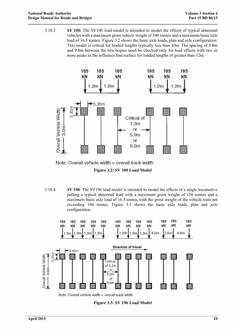
3.10.3 SV 100. The SV100 load model is intended to model the effects of typical abnormal vehicles with a maximum gross vehicle weight of 100 tonnes and a maximum basic axle load of 16.5 tonnes. Figure 3.2 shows the basic axle loads, plan and axle configuration. This model is critical for loaded lengths typically less than 10m. The spacing of 5.0m and 9.0m between the two bogies need be checked only for load effects with two or more peaks in the influence line/surface for loaded lengths of greater than 12m.
Figure 3.2: SV 100 Load Model
3.10.4 SV 196. The SV196 load model is intended to model the effects of a single locomotive pulling a typical abnormal load with a maximum gross weight of 150 tonnes and a maximum basic axle load of 16.5 tonnes with the gross weight of the vehicle train not exceeding 196 tonnes. Figure 3.3 shows the basic axle loads, plan and axle configuration.
Figure 3.3: SV 196 Load Model
National Roads Authority Volume 3 Section 4 Design Manual for Roads and Bridges Part 15 BD 86/15
April 2015 11
3.11. Abnormal Vehicles Outside the Scope of the SV Load Models
3.11.1 For a specific abnormal vehicle that is outside the scope of the SV load models defined in 3.10, the vehicle shall be assessed initially by comparing its load effect against the load effect from a SV load model with the associated Reserve Factor using one or more influence lines considered most appropriate for the structure.
3.11.2 In 3.11.1, if the load effect from the vehicle exceeds the load effect from the SV load model, then the structure shall be assessed directly using this vehicle, with the values of DAF, OF, γfL and γf3 applied in the same way as they are for SV load models.
3.11.3 For loaded lengths of up to 50m, associated Type HA loading (representing C&U vehicle loading) (3.19 - 3.31) shall be applied. For loaded lengths in excess of 50m, advice shall be sought from the National Roads Authority.
3.12. Assessment for Exceptional Abnormal Load Vehicles Using SOV Load Models
3.12.1 The following four SOV load models simulate vertical effects of Exceptional Abnormal Load vehicles with trailer weights limited to:
(i) SOV-250 - Maximum total weight of trailer units up to 250 tonnes;
(ii) SOV-350 - Maximum total weight of trailer units up to 350 tonnes;
(iii) SOV-450 - Maximum total weight of trailer units up to 450 tonnes;
(iv) SOV-600 - Maximum total weight of trailer units up to 600 tonnes.
3.12.2 The load models do not describe actual vehicles but have been chosen so that their effects, combined with Dynamic Amplification Factor, represent the extreme effects that could be induced by real exceptional abnormal load vehicles.
3.12.3 The choice of the particular SOV load model for the assessment of structures on motorways, national roads and other minor roads shall be agreed with the National Roads Authority. It should be noted that no structure will have been designed for such a loading regime.
3.12.4 The SOV load models are applicable to exceptional abnormal load vehicles within the axle load and configuration limits defined in Table 3.1.
National Roads Authority Volume 3 Section 4 Design Manual for Roads and Bridges Part 15 BD 86/15
April 2015 12
Configuration parameter Limiting Value
Tractor
Maximum weight of the front axle in a 4-axle tractor 10 tonnes
Maximum weight of any of the rear three axles in a 4-axle tractor or any axle in a 3-axle tractor
16.5 tonnes
Minimum spacing between the 1st and 2nd axle 1.85m
Minimum spacing between the 2nd and 3rd axle (only for a 4-axle tractor) 1.35m
Minimum spacing between the two rear axles 1.35m
Trailer
Maximum axle weight 22.5 tonnes
Minimum spacing between trailer axles 1.5m
Minimum spacing between rear axle of the tractor and the front axle of the trailer (or rear axle of trailer and front axle of tractor)
5.0m
Maximum spacing between the two trailer units 40.0m
Minimum outside track of trailer axles 2.75m
Table 3.1: Limits on Exceptional Abnormal Load Vehicle Configuration Parameters Applicable for
SOV Load Models
3.13. Basic Axle Load and Configuration of SOV Load Models
3.13.1 The longitudinal configuration of the four load models are shown in Figure 3.6. The standard configuration has a trailer with two bogies and two tractors; one pulling and one pushing. However, on structures located on a stretch of road with a gradient steeper than 1 in 25, six tractor units, in any combination of pulling and pushing that produces the worst effect, shall be considered for assessment.
National Roads Authority Volume 3 Section 4 Design Manual for Roads and Bridges Part 15 BD 86/15
April 2015 13
(a) SOV-250 Load Model
(b) SOV-350 Load Model
(c) SOV-450 Load Model
(d) SOV-600 Load Model
Note to figures (a) to (d): For simplicity, not all the axles on the trailers are shown. The actual number of axles of trailer bogie should be that stated above the figure.
Figure 3.6: Basic Longitudinal Configuration of SOV Load Models
National Roads Authority Volume 3 Section 4 Design Manual for Roads and Bridges Part 15 BD 86/15
April 2015 14
3.13.2 The lateral wheel arrangement for the trailer axles of all the SOV load models shall be
in accordance with Figure 3.7. All the wheels are of equal weight. The tractor axles of the load models have two wheels, each of equal weight, with outside track and overall width of 3.0m.
Figure 3.7: Lateral Wheel Arrangement for Trailer Axles of all SOV Load Models
3.14. Exceptional Abnormal Load Vehicles Outside the Scope of the SOV Load Models
3.14.1 For a specific exceptional abnormal load vehicle that is outside the scope of the SOV load models defined in 3.12, the vehicle shall be assessed initially by comparing its load effect against the load effect from a SOV load model with the associated Reserve Factor using one or more influence lines considered most appropriate for the structure. The procedures given in C.3 to C.6 shall be used for this purpose, substituting 'SOV' for 'SV' and 'Exceptional Abnormal' for 'Abnormal' as appropriate.
3.14.2 In 3.14.1, if the load effect from the vehicle exceeds the load effect from the SOV load model, then the structure shall be assessed directly using this vehicle, with the values of DAF, OF, γfL and γf3 applied in the same way as they are for SOV load models.
3.14.3 For loaded lengths of up to 50m, associated Type HA loading (representing C&U vehicle loading) (3.19 - 3.31) shall be applied. For loaded lengths in excess of 50m, advice shall be sought from the National Road Authority.
Wheel Contact Areas
3.15. The wheel loads for SV load models shall be uniformly distributed over a square or rectangular contact area as shown in Figures 3.1 to 3.5. The wheel loads for SOV load models shall be uniformly distributed over a square contact area of 0.35m x 0.35m as shown in Figure 3.7. For specific abnormal or exceptional abnormal load vehicles the contact areas shall be as given in the notifications by the hauliers. In the absence of such information, the load from each wheel of the vehicle shall be taken as uniformly distributed over a square contact area of 0.35m x 0.35m.
Dispersal of Wheel Loads
3.16. The dispersal of wheel loads through surfacing, filling material and structural concrete slabs shall follow the procedures given in NRA BD 21. This also applies to trough decks and masonry arches.
National Roads Authority Volume 3 Section 4 Design Manual for Roads and Bridges Part 15 BD 86/15
April 2015 15
Overload Factor
3.17. The Overload Factor models the overloading of SV or SOV load models in excess of the gross weight and axle weights notified by the hauliers to road authorities. The Overload Factor (OF) shall be taken as 1.2 for the worst critical axle and 1.1 for all other axles of SV or SOV load models.
Dynamic Amplification Factor
3.18. The Dynamic Amplification Factor (DAF) for each axle of SV or SOV load model shall be calculated as given below:
1.7x.
1.05 (3.1)
where qka is the basic axle load in kN. Note that the DAF values could be different for the different axles depending on their loads. The variation of DAF with basic axle load is illustrated in Figure 3.8.
Figure 3.8: Dynamic Amplification Factor as a Function of Basic Axle Load qka
Associated Type HA Loading (representing C&U Vehicle Loading)
3.19. The effects of normal vehicles (those that conform to the C&U Regulations) associated with SV or SOV load models, and specific abnormal or exceptional abnormal vehicles shall be represented by the associated Type HA loading in accordance with NRA BD 21.
3.20. Separate assessments are not required for single wheel loads or single axle loads from C&U vehicle loading associated with an SV or SOV load model.
National Roads Authority Volume 3 Section 4 Design Manual for Roads and Bridges Part 15 BD 86/15
April 2015 16
Application of SV or SOV Load Models and Associated Type HA Loading (representing C&U Vehicle Loading)
3.21. SV or SOV load models and associated Type HA loading (representing C&U vehicle loading) shall be combined and applied as follows:
(i) Associated Type HA loading shall be applied to the notional lanes of the carriageway as 2.5m wide strips in accordance with NRA BD 21.
(ii) Only one SV or SOV load model shall be considered on any one superstructure.
3.22. The SV or SOV load model can be placed at any transverse position on the carriageway, either wholly within one notional lane or straddling between two adjacent lanes, with its side parallel to the kerb. The SV or SOV load model shall be placed at the most unfavourable position transversely and longitudinally over the loaded length, in order to produce the most severe load effect at the section being considered.
3.23. The design load effects shall be determined from the maximum of the two cases:
(i) SV or SOV load model moving at 'normal' speed; and
(ii) SV or SOV load model moving at 'low' speed (< 10 mph).
3.24. Where the SV or SOV load model lies fully within a notional lane and is moving at 'normal' speed the associated Type HA loading shall not be applied within 25 metres from the centre of outer axles (front and rear) of the SV or SOV load model in that lane. This is illustrated in Figure 3.9(a). The Dynamic Amplification Factor shall be taken as given in 3.18.
3.25. Where the SV or SOV load model lies fully within a notional lane and is moving at 'low' speed the associated Type HA loading shall not be applied within 5 metres from the centre of outer axles (front and rear) of the SV or SOV load model in that lane. This is illustrated in Figure 3.9(b). The Dynamic Amplification Factor shall be taken as 1.0.
3.26. The remainder of the adverse areas within the loaded length in the lane occupied by the SV or SOV load model shall be loaded with associated Type HA UDL (uniformly distributed load) only; Type HA KEL (knife edge load) shall be omitted. The intensity of the Type HA UDL shall be based on the total loaded length of the adverse areas within the length and not the reduced length over which the Type HA UDL is applied. This is illustrated in Figures 3.9 (a) and (b).
National Roads Authority Volume 3 Section 4 Design Manual for Roads and Bridges Part 15 BD 86/15
April 2015 17
Figure 3.9: Typical Application of Type SV or Type SOV and Associated Loading when the SV or SOV Load Model Lies Fully Within a Notional Lane
Figure 3.10: Typical Application of Type SV or Type SOV and Associated Type HA Loading when the SV or SOV Load Model Straddles Two Adjacent Notional Lanes
National Roads Authority Volume 3 Section 4 Design Manual for Roads and Bridges Part 15 BD 86/15
April 2015 18
3.27. Where the SV or SOV load model lies partially within a notional lane and the remaining width of the lane, measured from the side of the SV or SOV load model to the far edge of the notional lane, is less than 2.5m (Figure 3.10(a)), the associated Type HA UDL shall not be applied to that lane within 25m of the centre of the outer axles (front and rear) of the SV or SOV load model, for the 'normal' speed case. For the 'low' speed case, the Type HA UDL shall not be applied within 5m of the centre of the outer axles (front and rear) of the SV or SOV load model.
3.28. Where the SV or the SOV load model lies partially within a notional lane and the remaining width of the lane, measured from the side of the SV or SOV load model to the far edge of the notional lane, is greater or equal to 2.5m, the Type HA UDL loading in that lane shall remain (Figure 3.10 (b)) but the Type HA KEL shall be omitted.
3.29. On the remaining lanes not occupied by the SV or SOV load model, the associated Type HA loading (UDL and KEL) with appropriate Lane Factors shall be applied in accordance with NRA BD 21. This is illustrated in Figures 3.9(a) and (b) and 3.10(a) and (b) for typical configurations of Type HA loading in combination with Type SV or Type SOV loading.
3.30. All of the notional lanes and their corresponding Lane Factors are interchangeable for producing the most severe load effect.
3.31. Figures 3.9 and 3.10 shall also be applied to assessments based on specific abnormal and exceptional abnormal vehicles.
Transverse Members
3.32. As an exception to 3.21 to 3.31, for transverse cantilever slabs, slabs supported on all four sides, cross-girders and slabs spanning transversely (including skew slabs with significant transverse action), the associated Type HA loading shall be replaced with the C&U vehicle loading and applied as a single vehicle or convoy of vehicles in accordance with Annex D of NRA BD 21. The travelling speed of SV or SOV load models may be different from that of the associated C&U vehicles. However, if a convoy of vehicles is assumed for the associated C&U vehicles, SV or SOV load models should only be considered at the 'low' speed case.
3.33. Transverse trough decks shall be assessed for SV or SOV load models considering loading from all the axles, including OF and DAF. The associated Type HA loads shall be assessed on the basis of a single axle and/or single wheel load of C&U vehicles per lane with trough enhancement factors as given in NRA BD 21.
Centrifugal Effects
3.34. The vertical effects arising from centrifugal forces on horizontally curved carriageways shall be determined for SV loading using the method given in NRA BD 21assuming speeds practicable for real abnormal vehicles in the range between 30 and 50mph. The centrifugal effects of SOV loading may be ignored.
Longitudinal Loading
3.35. The longitudinal loading (see reference 5) shall be taken as the most severe of the braking or traction force determined as follows:
For SV or SOV Load Models
3.35.1 Braking force of 50% of the basic axle loads for the SV80 load model; 40% for SV100; 25% for SV196 and 20% for all SOV load models, applied to each corresponding axle of the SV or SOV Load Model.
National Roads Authority Volume 3 Section 4 Design Manual for Roads and Bridges Part 15 BD 86/15
April 2015 19
3.35.2 Acceleration force of 10% of the gross weight for all SV and SOV load models distributed between the axles in the same proportion as the vertical loads.
For a Specific Abnormal Vehicle
3.35.3 The longitudinal load shall be taken from whichever of the following produces the most severe effect:
(i) a braking force of 50% of the gross weight for an 80 tonne abnormal load; 40% for a 100 tonne abnormal load vehicle and 25% for an abnormal load vehicle over 100 tonnes gross weight, distributed proportionally to the loads carried by the individual braking axles;
(ii) a traction force of 10% of the gross weight of the abnormal load vehicle distributed proportionally to the loads carried by the individual driving axles.
For a Specific Exceptional Abnormal Load Vehicle
3.35.4 The braking load shall not be considered for assessment if the vehicle is controlled (i.e. the vehicle is escorted). Where the exceptional abnormal load vehicle is not escorted, the longitudinal load shall be taken from whichever of the following produces the most severe effect:
(i) a braking force of 20% of the gross weight of the exceptional abnormal load vehicle distributed proportionally to the loads carried by the individual braking axles;
(ii) a traction force of 10% of the gross weight of the exceptional abnormal load vehicle distributed proportionally to the loads carried by the individual driving axles.
Masonry Arches
3.36. As an exception to 3.21 to 3.31, when alternative methods to MEXE (see NRA BD 21and NRA BA 16) are used for the assessment of masonry arches, the associated Type HA loading shall be replaced with the loading from single, double and triple axles of C&U vehicles given in NRA BD 21 with the corresponding conversion factors to account for axle lift-off. For arch spans greater than 20m, a separate assessment shall also be made with the Type HA UDL and KEL loading.
3.37. Where conditions on an arch bridge are likely to cause lift-off (see NRA BA 16), a triple-axle bogie must be assumed within the SV or SOV load model comprising the worst effective axle and the following two axles. For the case of a SV or SOV load model travelling at 'normal' speed, a lift-off factor of 1.2 shall be applied to the leading axle and a factor of 0.8 to the trailing axle of this bogie. No lift-off shall be applied to the remaining axles. The lift-off requirement shall not apply to SV or SOV load models for the 'low' speed case.
3.38. Alternative analysis to the MEXE method shall be used where the geometry of the arch is such that three or more axles of the SV or SOV load model can be applied in half of the span whilst the remaining half is not loaded.
3.39. The factors of safety γfL for the assessment of masonry arches when using alternative methods to MEXE shall be 2.0 for SV or SOV loading and associated Type HA loading or C&U vehicle loading. In addition, the effects of OF and DAF shall be included.
National Roads Authority Volume 3 Section 4 Design Manual for Roads and Bridges Part 15 BD 86/15
April 2015 20
Buried Structures
3.40. For buried concrete box type structures (cover greater than 0.6m), the associated Type HA loading shall be replaced with C&U vehicle loading in accordance with NRA BA 55. The wheel loads shall be dispersed from the carriageway to the top of the buried structure in accordance with NRA BA 55. Dynamic effects for abnormal, exceptional abnormal and C&U vehicles or their respective load models may be reduced for buried structures in accordance with NRA BA 55.
Choice of SV and SOV Load Models for Assessment
3.41. The Assessment shall be carried out for all SV load models and for selected (as agreed with the National Roads Authority) SOV load models. For all load models assessed, Reserve Factors shall be determined and recorded in the National Roads Authority’s Eirspan bridge management system.
3.42. Ascertain the governing SV load models for the loaded length and the load effect being considered, and assess the structure for this load model. The following is tentative guidance and should be verified by the Structural Assessment Engineer:
(i) For loaded lengths of between 5m and 10m, the SV 100 load model generally governs.
(ii) For loaded lengths of greater than 10m, the SV 196 load model generally governs.
(iii) If the Reserve Factor is greater than or equal to 1.0 for the above appropriate load case, other SV load models are likely to be less critical.
(iv) For loaded lengths of less than 5m, heavy axle loads generally govern.
3.43. For structures where the capacity is less than the load effects from the above load models, the structure can generally be assessed for SV load models in the following order:
(i) SV-100 model. When a structure can sustain the SV-100 model it can generally sustain the SV-80 load model.
(ii) SV-196 load model. When a structure can sustain the SV-196 load model, it can generally sustain the SV-100 (for spans greater than 10m) and SV-80 models.
3.44. The assessments should initially be carried out with the associated Type HA loading. If the Reserve Factor is greater than or equal to 1.0 for any SV load model, assessment without the associated Type HA loading is not necessary.
3.45. For short span structures (less than 20m), the normal speed case will generally govern, due to the application of the Dynamic Amplification Factor.
National Roads Authority Volume 3 Section 4 Design Manual for Roads and Bridges Part 15 BD 86/15
April 2015 21
Reserve Factors 3.46. For each SV or SOV load model considered, a Reserve Factor, ΨSV, or ΨSOV shall be established.
This is defined as the factor on the assessment SV or SOV load required to reach the first failure. For example, where elastic methods are used and there is no interaction between load effects, the Reserve Factor ΨSV or ΨSOV can be calculated as follows:
With Associated Type HA Loading
Ψ orΨ∗ ∗ ∗
∗ (3.2)
Without Associated Type HA Loading
Ψ∗ orΨ∗∗ ∗
∗ (3.3)
where:
RA* assessment resistance (flexure, shear, etc.)
SD* assessment load effect due to combined dead and superimposed dead loads
SHA* assessment load effect due to the associated Type HA loading (or C&U vehicle loading)
S* assessment load effect due to the SV or SOV load model
Vehicle Rating
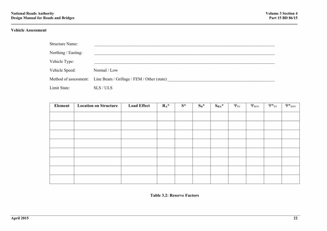
3.47. The Reserve Factors for each SV and SOV load model may be given in a tabular form similar to that shown in Table 3.2. Certain types of structures (cast iron, masonry arches, for example) may not yield a directly comparable Reserve Factor, and their ability to sustain vehicles needs to be considered separately for each load case.
3.48. The Vehicle Rating for a structure shall be taken as the most onerous SV and SOV load model that can safely pass over the structure (i.e. the load model with the smallest Reserve Factor ΨSV and ΨSOV
greater than or equal to 1.0).
National Roads Authority Volume 3 Section 4 Design Manual for Roads and Bridges Part 15 BD 86/15
Method of assessment: Line Beam / Grillage / FEM / Other (state) __________________________________________________
Limit State: SLS / ULS
Element Location on Structure Load Effect RA* S* SD* SHA* ΨSV ΨSOV Ψ*SV Ψ*SOV
Table 3.2: Reserve Factors
National Roads Authority Volume 3 Section 4 Design Manual for Roads and Bridges Part 15 BD 86/15
April 2015 23
4. REFERENCES 4.1. The following documents are referred to in the text of this Standard:
1. Cooper, D.I. (1997): Development of short span bridge-specific assessment live loading, In Safety of Bridges (Ed.) Parag C. Das, Thomas Telford.
2. Ricketts, N.J. (1997): Collection of statistical data, In Safety of Bridges (Ed.) Parag C. Das, Thomas Telford.
3. The following is a list of documents in the NRA Design Manual for Roads and Bridges to which reference is made in this Standard:
NRA BD 21 The Assessment of Road Bridges and Structures
NRA BA 16 The Assessment of Road Bridges and Structures
NRA BD 37 Loads for Road Bridges
NRA BA 55 The Assessment of Bridge Substructures and Foundations, Retaining Walls and Buried Structures
NRA BD 56 The Assessment of Steel Road Bridges and Structures
NRA BD 61 The Assessment of Composite Road Bridges
NRA BD 101 Structural Review and Assessment of Road Structures
4. The following is a list of Statutory Instruments to which reference is made in this Standard:
The Road Traffic (Construction & Use of Vehicles) Regulations 2003, as amended
5. McMahon, W. (2004): Measurements of braking forces from abnormal loads: implications for design and assessment standards. TRL Report 618, TRL Limited, Crowthorne.
6. McMahon, W. (2006): The characteristics of Special Order vehicles, TRL Published Report No. PPR101.
National Roads Authority Volume 3 Section 4 Design Manual for Roads and Bridges Part 15 BD 86/15
April 2015 24
5. ENQUIRIES 5.1. All technical enquiries or comments on this document or any of the documents listed as forming part
of the NRA DMRB should be sent by e-mail to [email protected], addressed to the following:
“Head of Network Management, Engineering Standards & Research National Roads Authority St Martin’s House Waterloo Road Dublin 4”
…………..………………………………… Pat Maher Head of Network Management, Engineering Standards & Research
National Roads Authority Volume 3 Section 4 Design Manual for Roads and Bridges Part 15 BD 86/15
April 2015 A/1
ANNEX A ABNORMAL VEHICLE CATEGORIES A1. Introduction
In Ireland, vehicles whose weights do not comply with the Road Traffic (C&U) Regulations 2003, as amended, are termed abnormal vehicles. Abnormal vehicle categories assumed by the NRA for assessment purposes are based on abnormal vehicle categories defined within UK regulations. Road vehicles in the United Kingdom are categorised for regulatory purposes into three broad groups as follows:
1. Vehicles complying with the Road Vehicles Construction and Use (C&U) Regulations and Authorised Weight Regulations (AW). This group includes cars, light goods vehicles, and rigid and articulated heavy goods vehicles up to a gross weight of 44 tonnes. These vehicles are not subject to permit and notification requirements.
2. Vehicles complying with the Road Vehicles (Authorisation of Special Types_ General Order (STGO
Regulations). This group includes vehicles that do not comply with the AW Regulations such as those used for carrying or drawing abnormal indivisible loads. This Annex A pertains to such UK STGO vehicles.
NOTE: In Ireland, there is no comparable legislation. Such vehicles are termed “Abnormal Vehicles” by the NRA and require a permit to travel on the road network as they do not meet the requirements of the Irish C&U Regulations 2003, as amended.
3. Special Order (SO) Vehicles. This group includes vehicles that do not comply with the UK AW or
STGO Regulations and are covered by Section 44 of the UK 1988 Road Traffic Act.
NOTE: Again, in Ireland there is no comparable legislation, such vehicles are termed “Exceptional Abnormal vehicles” by the NRA and require a permit to travel similar to “Abnormal Vehicles” as described in 2) above.
The maximum gross and axle weights allowable in the UK under Schedule 1 of the STGO Regulations are briefly described below.
A2 Abnormal Indivisible Load Vehicles
These may consist of either Abnormal Indivisible Load Vehicles (AILVs) or an AILV and Trailer (AILV- combination). They are used for carrying or for drawing abnormal indivisible loads (e.g. industrial plant) up to a maximum weight of 150 tonnes. These vehicles are grouped into the three weight Categories given below.
(a) Category 1 AILVs and AILV-combinations (up to 46 tonnes)
AILVs and AILV-combinations in this category will have a minimum of five axles and must comply with the AW or C&U Regulations with regard to maximum vehicle weight, axle weights and spacing. The total weight of a Category 1 AILV-combination carrying a load must not exceed 46 tonnes. However, vehicles with six or more axles that comply in all other respects with the AW Regulations that apply to a vehicle combination of 44 tonnes, the gross weight can be up to 50 tonnes. The Type HA loading covers the effects of these vehicles and hence these are not specifically included in the Type SV loading.
(b) Category 2 AILVs and AILV combinations (up to 80 tonnes)
Vehicles in this category must have a minimum of six axles and the spacing between any two adjacent axles must not be less than 1m. Total weight of AILV or AILV-combination carrying a load must not exceed 80 tonnes. The weight, in kilograms, of AILV or AILV-combination must be calculated as D x 7,500 and then round up to the nearest 10 kilograms, where D is taken as the distance, in metres, between the foremost axle
National Roads Authority Volume 3 Section 4 Design Manual for Roads and Bridges Part 15 BD 86/15
April 2015 A/2
and the rearmost axle of the AILV carrying the load or in the case of an articulated AILV-combination, the kingpin and the rearmost axle on the semi-trailer. Maximum permitted values of axle weight and minimum axle spacing are shown in Table A.1.
Where the axles are in two or more groups and adjacent axles of different groups are more than 2m apart, then the total weight from all axles in any one group must not exceed 50 tonnes.
Spacing between any two adjacent
axles (m)
Maximum Axle Weight (tonnes)
Maximum Wheel Weight
(tonnes)
< 1.35 12 6
≥ 1.35 12.5 6.25
Table A.1: Maximum Axle Weight and Minimum Spacing for Category 2 Vehicles
(c) Category 3 AILVs and AILV-combinations (up to 150 tonnes)
Vehicles in this category must have a minimum of six axles and the spacing between any two adjacent axles must not be less than 1m. Total weight of a Category 3 AILV or AILV-combination carrying a load must not exceed 150 tonnes. The weight, in kilograms, of AILV or AILV-combination must be calculated as D x 12,500 and then round up to the nearest 10 kilograms, where D is taken as the distance, in metres, between the foremost axle and the rearmost axle of the AILV carrying the load or in the case of an articulated AILV- combination, the kingpin and the rearmost axle on the semi-trailer. Maximum permitted values of axle weight and minimum axle spacing are shown in Table A.2.
Where the axles are in two or more groups and adjacent axles of different groups are more than 1.5m apart, then the total weight from all axles in any one group must not exceed 100 tonnes. This will be limited to 90 tonnes for a group if the spacing between adjacent axles for that group is less than 1.35m.
Spacing between any two adjacent
axles (m)
Maximum Axle Weight (tonnes)
Maximum Wheel Weight
(tonnes)
< 1.35 15 7
≥ 1.35 16.5 8.25
Table A.2: Maximum Axle Weight and Minimum Spacing for Category 3 Vehicles
Note that the above weight limits apply to vehicles or a combination of vehicles carrying the load. Vehicles drawing the abnormal indivisible load but not carrying any part of the load are assessed separately. Thus for example, the total weight of the vehicle train i.e. a locomotive pulling a trailer carrying the abnormal load, can exceed the maximum limits for the above respective vehicle categories.
National Roads Authority Volume 3 Section 4 Design Manual for Roads and Bridges Part 15 BD 86/15
April 2015 B/1
ANNEX B BASIS OF SV AND SOV LOAD MODELS FOR ASSESSMENT
B1 Background
For the purposes of this Annex the abnormal vehicles (STGO vehicles) are real vehicles conforming to the UK STGO Regulations. The STGO (Special Types General Order) Regulations govern vehicles that do not conform to the UK Authorised Weight (AW) Regulations for reasons of gross weight, height, length and/or axle weight and spacing configurations.
Exceptional abnormal vehicles (SO (Special Order) Vehicles) are real vehicles that do not conform to the UK AW Regulations or the UK STGO Regulations, but are covered by Section 44 of the 1988 Road Traffic Act in the UK.
Until the introduction of Eurocodes, bridges and other road structures designed using BS 5400 should have been designed for the Type HB loading given in NRA BD 37, which is intended to cover the effects of abnormal load vehicles.
The Type HB loading model has also been used in assessment to assess for the effects of abnormal load vehicles as there was no assessment standard available. Studies have shown that the Type HB loading model does not represent accurately the effects of real abnormal vehicles. In particular, because of the high axle weights, the Type HB model is excessively conservative for very short span structures. However, this conservatism reduces for spans of 15m to 30m, and in fact it is seen that real abnormal vehicles can produce more severe load effects than a Type HB model vehicle of the same gross weight. This is because the real abnormal vehicles have more axles which are more closely spaced than those of the Type HB model vehicle.
In the case of Exceptional Abnormal load vehicles, structures on the notified route should be checked for their adequacy to support each notified vehicle. The checking could involve a simple comparative assessment of the actual Exceptional Abnormal load vehicle against the Type HB capacity for the structures or in some cases a full structural assessment may be carried out using the notified vehicle. Structures which are deficient may require strengthening to carry the Exceptional Abnormal load vehicle if a suitable alternative route cannot be found. This approach could result in considerable delays and costs to the industry, as well as imposing an administrative burden on road authorities.
Standard SV and SOV load models given in this standard were developed to cater for the effects of the majority of abnormal load and exceptional abnormal load vehicles to expedite the process of clearing movement requests.
B2 Comparison of Type HB Loading against the Effects of Real Abnormal and Exceptional Abnormal Vehicles
In the early 1990’s, a number of studies were undertaken in the UK. One such study included a comparison of the effects of abnormal load vehicles (STGO) and exceptional abnormal load vehicles (SO) vehicles with the effects of the HB loading which was used in the design of bridges at the time.
Figures B.1 and B.2 compare the load effects produced by STGO Category 3 and Category 2 vehicles, respectively, against various units of Type HB loading. The effects from STGO vehicles are based on an extensive database of STGO vehicle notifications and the data from a weigh-in-motion station on the M40 motorway in the UK, and represent the maximum values obtained at each span. Effects from hypothetical vehicles that conform to the extreme allowable limits of the existing STGO regulations are also included for comparison.
National Roads Authority Volume 3 Section 4 Design Manual for Roads and Bridges Part 15 BD 86/15
April 2015 B/2
In the above comparison, overloading and dynamic amplification factors are not included in calculating STGO load effects and no partial factors are applied to the effects from Type HB vehicles. The influence line for the mid-span moment of a simply supported beam is used, and it is assumed that there will be only one abnormal vehicle on the bridge at any one time. Associated Type HA loading or AW vehicle loading has not been applied.
From these figures it can be seen that the 45 units of Type HB loading (used for the design of structures carrying motorway and national roads), although encompassing the effects of all STGO vehicles, can be excessively conservative for structures less than about 10m span.
37.5 units of Type HB loading (with a gross weight of 150 tonnes), on the other hand, although it is conservative for spans of less than 10m, on longer spans it does not cater for the effects produced by STGO Category 3 vehicles with gross weights of up to 150 tonnes. Similarly, 25 units and 20 units of Type HB loading do not cater for the effects of Category 3 vehicles of up to 100 tonnes and Category 2 vehicles of up to 80 tonnes gross weight respectively.
National Roads Authority Volume 3 Section 4 Design Manual for Roads and Bridges Part 15 BD 86/15
April 2015 B/3
Figure B.1: Comparison of STGO Category 3 Vehicle Effects Against Type HB Loading
Figure B.2: Comparison of STGO Category 2 Vehicle Effects Against Type HB Loading
National Roads Authority Volume 3 Section 4 Design Manual for Roads and Bridges Part 15 BD 86/15
April 2015 B/4
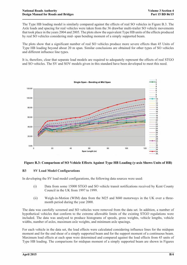
The Type HB loading model is similarly compared against the effects of real SO vehicles in Figure B.3. The Axle loads and spacing for real vehicles were taken from the 36 drawbar multi-trailer SO vehicle movements that took place in the years 2004 and 2005. The plots show the equivalent Type HB units of the effects produced by real SO vehicles considering mid- span bending moment of a simply supported beam.
The plots show that a significant number of real SO vehicles produce more severe effects than 45 Units of Type HB loading beyond about 20 m span. Similar conclusions are obtained for other types of SO vehicles and different influence line types.
It is, therefore, clear that separate load models are required to adequately represent the effects of real STGO and SO vehicles. The SV and SOV models given in this standard have been developed to meet this need.
Figure B.3: Comparison of SO Vehicle Effects Against Type HB Loading (y-axis Shows Units of HB) B3 SV Load Model Configurations
In developing the SV load model configurations, the following data sources were used:
(i) Data from some 15000 STGO and SO vehicle transit notifications received by Kent County Council in the UK from 1997 to 1999.
(ii) Weigh-in-Motion (WIM) data from the M25 and M40 motorways in the UK over a three-month period during the year 2000.
The data was carefully screened and SO vehicles were removed from the data set. In addition, a number of hypothetical vehicles that conform to the extreme allowable limits of the existing STGO regulations were included. The data was analysed to produce histograms of speeds, gross weights, vehicle lengths, vehicle widths, number of axles, maximum axle weights, and minimum axle spacings.
For each vehicle in the data set, the load effects were calculated considering influence lines for the midspan moment and for the end shear of a simply supported beam and for the support moment of a continuous beam. Maximum load effects at each span were determined and compared against the load effects from 45 units of Type HB loading. The comparisons for midspan moment of a simply supported beam are shown in Figures
National Roads Authority Volume 3 Section 4 Design Manual for Roads and Bridges Part 15 BD 86/15
April 2015 B/5
B.1 and B.2. Partial Factors, Overload Factor, DAF and associated Type HA loading or AW vehicle loading are not included in these comparisons.
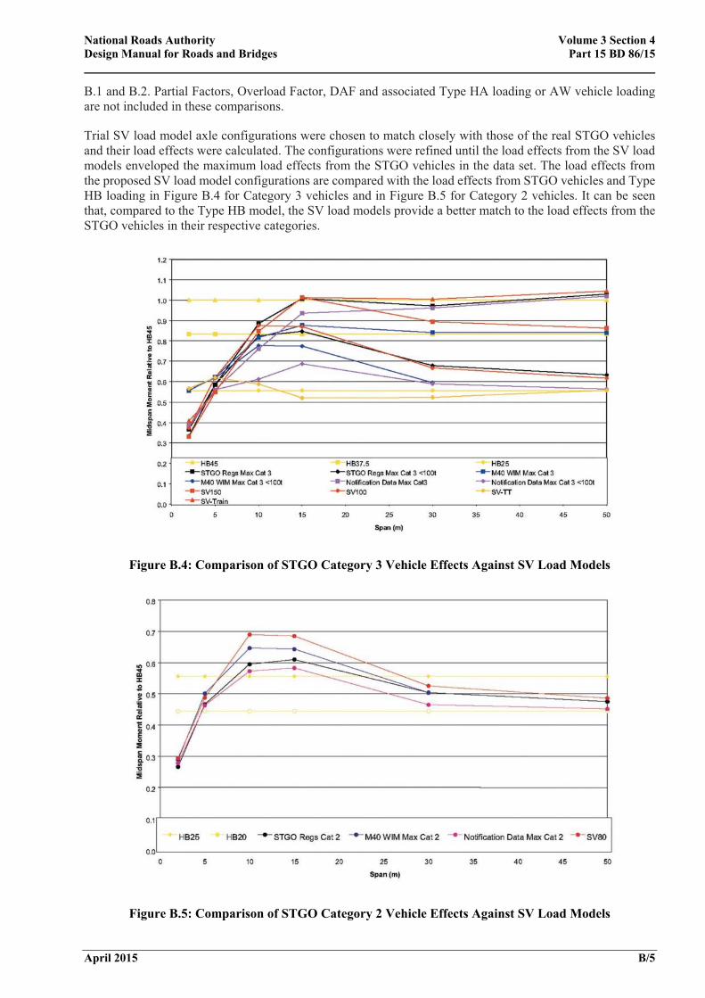
Trial SV load model axle configurations were chosen to match closely with those of the real STGO vehicles and their load effects were calculated. The configurations were refined until the load effects from the SV load models enveloped the maximum load effects from the STGO vehicles in the data set. The load effects from the proposed SV load model configurations are compared with the load effects from STGO vehicles and Type HB loading in Figure B.4 for Category 3 vehicles and in Figure B.5 for Category 2 vehicles. It can be seen that, compared to the Type HB model, the SV load models provide a better match to the load effects from the STGO vehicles in their respective categories.
Figure B.4: Comparison of STGO Category 3 Vehicle Effects Against SV Load Models
Figure B.5: Comparison of STGO Category 2 Vehicle Effects Against SV Load Models
National Roads Authority Volume 3 Section 4 Design Manual for Roads and Bridges Part 15 BD 86/15
April 2015 B/6
B4 Configuration of SOV Load Models
Unlike the STGO vehicles there are no regulations in the UK which control the configuration (i.e. axle load, spacing etc.) of SO vehicles. As a result it is not feasible to develop standard loading models to cater for the effects of virtually any configuration of SO vehicle. However, if certain limits on key vehicle configuration parameters can be agreed it is possible to develop standard models to cater for SO vehicles within these limits.
The data held by the Highways Agency in the UK on some 450 SO vehicles over 150 tonnes moved over the period 2000 to 2005 was examined. However, detailed data on vehicle characteristics were available only for some 130 vehicles which were moved during the years 2004 and 2005 (see reference 6). Analysis of this data showed that standard models can be developed to cater for over 95% of SO vehicles of the following types that are commonly used:
• articulated tractor and semi-trailer vehicles;
• drawbar trailer vehicles;
• girder frame trailer vehicles.
The self-propelled modular trailers (SPMT) are seen to move over very short distances typically within a factory or construction yard to carry very large and prefabricated structures. They have quite unique configurations and it would be difficult to standardise these. Hence SPMT vehicles were excluded from the development of standard models. Structures would need to be designed and assessed individually for these vehicles.
Load effects were calculated for all the SO vehicles over 150 tonnes recorded during 2004 and 2005. The vehicle effects were converted to equivalent Type HB Units and plotted as illustrated in Figure B.3. It can be seen that the effects of real vehicles range from some 20 to 140 equivalent Units of Type HB. Based on the results of load effects critical vehicles from each type were identified.
Four standard loading models were developed to cater for vehicles with maximum trailer weights as below:
SOV-250 - Maximum total weight of SO trailer units up to 250 tonnes
SOV-350 - Maximum total weight of SO trailer units up to 350 tonnes
SOV-450 - Maximum total weight of SO trailer units up to 450 tonnes
SOV-600 - Maximum total weight of SO trailer units up to 600 tonnes
This gives flexibility for road authorities to assess structures on a route to cater for SO vehicles most likely to use that route.
The configuration of the SOV models (i.e. axle and wheel load arrangements of tractors and trailers) were established considering the general characteristics of real SO vehicles and based on an examination of the critical vehicles producing the most severe load effects.
Figure B.6 shows normalised results (load effect of real vehicle divided by the load effect of the load model) for all critical vehicles with trailer weights of up to 350 tonnes considering a range of influence line types. For comparison, equivalent values for 45 Units of Type HB are also included. The maximum values (ignoring the diamonds representing the Type HB vehicle) are all less than 1.0 suggesting that the SOV-350 model safely envelopes the load effects from critical vehicles in the abnormal database.
Comparison of the entire SOV load models were made against the real vehicles recorded in the database using beam influence lines of varying spans for five different load effects and four real bridges of different structural forms. The results confirmed that the SOV models closely represent the effects of real SO vehicles and optimally cater for the most severe effects of real SO vehicles within the specified configuration limits. In
National Roads Authority Volume 3 Section 4 Design Manual for Roads and Bridges Part 15 BD 86/15
April 2015 B/7
comparison the Type HB model is seen to be very conservative for spans less than about 15 m but becomes increasingly less onerous than the effects of real vehicles even for trailer weights up to 250 tonnes.
Figure B.6: Comparison of Real SO Vehicle Effects Against SOV Load Models
B5 Overload Factor
STGO vehicles may be overloaded above the weights notified by the hauliers. The WIM data was compared with the data from notifications for the same route and the same period to get some indication of the overloading. Although it is not possible to identify individual vehicles from the WIM data, generally a greater number of heavier vehicles were observed in the WIM data compared to the notifications. In particular, there was a large number of vehicles with axle weights heavier than 16.5 tonnes (the upper limit for Category 3 STGOs) and further examination revealed that these were not SO vehicles. Significant overloading can occur on individual axles because of an uneven distribution of the total load to the different axles.
Based on the above observations, the Overload Factor was assumed to be 1.2 for the worst effective axle and 1.1 for all other axles of SV load models. As the number of axles present over the loaded length increases, the overall Overload Factor should reduce.
Since there is no data available on the levels of overloading of SO vehicles, this is assumed to be of similar order as the STGO vehicles and hence the same Overload Factors are used for both SV and SOV load models.
National Roads Authority Volume 3 Section 4 Design Manual for Roads and Bridges Part 15 BD 86/15
April 2015 B/8
B6 Dynamic Amplification Factor
Dynamic effects from vehicles arise principally from two sources: (i) whole-body bounce, and (ii) individual axle impact. A study carried out by Flint & Neill Partnership (see reference 1) based on measurements undertaken by TRL (see reference 2) established characteristic Dynamic Amplification Factors (DAF) for normal HGVs of 1.25 for 'good' road surfaces and 1.38 for 'poor' road surfaces. For structures close to 40m in span, where typical vehicle frequencies may match bridge frequencies, higher values than the above are possible. Although the dependency on speed was less significant at higher speeds, slow speed transits (at less than 10 mph) were seen to cause little dynamic response. Another important observation was that the dynamic component of the loading (not the factor) was relatively independent of the weight of the vehicle; so that the DAF actually decreases as the vehicle weight increases. This observation has been confirmed by a number of other studies carried out overseas.
There is no data available at present on the dynamic effects caused by abnormal vehicles. The STGO and SO vehicles could be expected to have lower DAF values than normal HGVs because of their heavier weights, lower speeds and generally better suspension systems.
It is also likely that axle impacts from different axles would be uncorrelated and hence the overall dynamic load should reduce as the number of axles on the loaded length increases, however, this effect could not be incorporated in the expression for DAF due to lack of data. Where the speed of the STGO or SO vehicle is restricted to less than 10 mph, the DAF factor is reduced to 1.0.
B7 Partial Load Factors for ULS
The partial load factor of 1.3 currently used on Type HB loading was assumed to cater for overloading and dynamic effects. Since these effects are explicitly considered in deriving the Type SV and Type SOV assessment live load, a lower partial load factor of 1.10 was adopted. The values of the partial factor, the Overload Factor and the Dynamic Amplification Factor were chosen together to ensure that the new SV model was no more onerous than the 45 units of Type HB loading which is the current design load level for motorway structures. The partial load factor on the Type HA loading associated with the Type SV or Type SOV loading is retained at 1.3 as at present.
B8 Lift-off Factors for Masonry Arches
Double and triple axle bogies do not compensate well over the crest of hump arch bridges. The current requirements in NRA BD 21 recognise that, with AW vehicles, the worst case in this respect occurs with steel suspension systems. For air or fluid suspension systems the lift-off factor is 1.0. This does not infer that there is no load transfer with air or fluid suspensions but that it is a significantly lower proportion. A large proportion of STGO and SO vehicles however have robust all-terrain fluid suspensions with high-unsprung axle weights. The inertia in these systems is likely to be significant and therefore a lift-off factor will need to be applied to the SV and SOV load models on structures where the lift- off condition is likely to occur.
B9 Limitations
The Type SV and Type SOV assessment loading models have the following limitations:
(i) The likelihood of two or more STGO and/or SO vehicles occurring simultaneously within a lane or in adjacent lanes over a bridge is not accounted for. This is not admissible in current regulations.
(ii) The models have been developed based on 'declared weights' from hauliers. The Overload Factor and the partial factor are intended to cater for minor unavoidable variations from declared weights that can occur in practice. The models do not cater for overloading due to negligence, deliberate under-declaration or lack of knowledge about axle loads of abnormal loads. This should be managed by stringent enforcement of the abnormal load movement system.
National Roads Authority Volume 3 Section 4 Design Manual for Roads and Bridges Part 15 BD 86/15
April 2015 B/9
(iii) The braking and acceleration forces specified are based on judgement and extrapolation of available test results; further research is needed to confirm these values.
(iv) The SV model does not cater for the possibility of locomotives heavier than that used for the SV-Train load model or for the possibility of more than one locomotive pushing or pulling the trailer.
National Roads Authority Volume 3 Section 4 Design Manual for Roads and Bridges Part 15 BD 86/15
April 2015 C/1
ANNEX C MANAGEMENT OF ABNORMAL VEHICLE MOVEMENTS
C1 General
When the Local Authority receives a notification from a haulier for the movement of an abnormal vehicle, the suitability of the vehicle to pass over a specific structure may be assessed using the procedures given in this Annex. A separate check should be made for adequate height and width clearances for the safe travel of the abnormal vehicle.
The assessment should be performed using the method given in C2.
Reductions to Dynamic Amplification Factor, the associated Type HA loading (representing C&U vehicle loading), and the Overload Factor may be made, e.g. where the transit is well regulated and there is a greater confidence in the weight of the abnormal vehicle as given in C3 to C5.
Local Authorities should be aware that checking for ULS only may result in serviceability problems and possible permanent damage. This is most likely where methods of analysis are used at ULS, which rely on large amounts of redistribution e.g. concrete structures.
Worked examples using the procedures in this Annex are given in C8 and C9.
C2 Detailed Assessment
The detailed assessment should be based on a comparison of the load effects caused by the abnormal vehicle with those of the SV load model using one or more influence lines considered most appropriate for the structure. Overload Factor (OF), Dynamic Amplification Factor (DAF) and partial factors γfL and γf3 should not be applied in calculating the load effects due to both the SV load model and abnormal vehicle as these factors would have already been incorporated in the calculation of the reserve factor for SV.
The calculation of load effects due to the abnormal vehicle and the SV load model should be refined in two steps as below:
(i) Calculate the unfactored load effects due to the abnormal vehicle, SABNORMAL, and the SV load model, SSV, ignoring the associated Type HA loading (representing C&U vehicle loading). The abnormal vehicle should be considered suitable to pass the structure if:
Ψ (C.1)
The above assumes that the load effects due to the associated Type HA loading (or C&U vehicle loading) is the same for both SV and abnormal vehicles. It is also an assumption that the structure being analysed has been designed to the particular SV Load Model being checked.
(ii) Where the inequality (C.2) is not satisfied, calculate the unfactored load effects due to both
abnormal and SV load models including the unfactored associated Type HA loading (or C&U vehicle loading) applied using 3.21 - 3.31 with the DAF set to 1.0. The abnormal vehicle should be considered suitable to pass the structure if the following condition is satisfied for both the 'normal speed' and 'low speed' cases:
Ψ (C.2)
National Roads Authority Volume 3 Section 4 Design Manual for Roads and Bridges Part 15 BD 86/15
April 2015 C/2
where SHA(ABNORMAL) is the unfactored load effect due to the Type HA loading (or C&U vehicle loading) associated with the abnormal vehicle, while SHA(SV) is the unfactored load effect due to the Type HA loading (or C&U vehicle loading) associated with the SV load model. This refinement is likely to be beneficial for loaded lengths greater than about 15m. In this case, since the real abnormal vehicles would in general be longer than the SV load models, SHA(ABNORMAL) would be lower than SHA(SV).
C3 Reduction in Dynamic Amplification Factor
For an abnormal vehicle that marginally exceeds the assessed capacity of a structure, it may be possible to permit its passage provided its speed over the structure can be restricted to less than 10 mph. The abnormal vehicle should be considered suitable to pass the structure if:
Ψ (C.3a)
where DAFABNORMAL=1.0 is the Dynamic Amplification Factor applied to the abnormal vehicle, while DAFSV is the Dynamic Amplification Factor applied to the SV load model taken as in 3.18.
Alternatively, when the effect due to the associated Type HA loading (or C&U vehicle loading) is taken into account the abnormal vehicle should be considered suitable to pass the structure if the following condition is satisfied for both the 'normal speed' and the 'low speed' case:
Ψ (C.3b)
In this case the Type HA loading should be applied using 3.21 - 3.31 assuming that the SV load model and abnormal vehicle lie fully within a notional lane (see Figure 3.9). The value of DAFSV should be taken as in 3.18 for the 'normal speed' case and as 1.0 for the 'low speed' case. For masonry arches the lift-off can be ignored for the 'low speed' case.
C4 Reduction in Associated Type HA Loading or AW Vehicle Loading
For an abnormal vehicle that marginally exceeds the assessed capacity of a structure, it may be possible to permit its passage provided the vehicle is escorted and the structure is kept clear of associated normal traffic. Two cases can be considered:
(i) When the associated traffic in the same lane as the abnormal vehicle is kept clear over the span, the abnormal vehicle should be considered suitable to pass the structure if the following condition is satisfied for both the 'normal speed' and the 'low speed' cases:
Ψ (C.4)
Where SHA(SV) is the load effect due to the Type HA loading (or C&U vehicle loading) in the same lane as the SV load model.
The load effects due to the SV load model and the associated Type HA loading (or C&U vehicle loading) should be calculated using 3.21 - 3.31 with the DAF set to 1.0. The reduction in the DAF can also be allowed for as in C3 if the speed of the abnormal vehicle over the structure is restricted.
(ii) When the associated traffic in all lanes of the carriageway is kept clear of the structure, the abnormal vehicle should be considered suitable to pass the structure if:
Ψ∗ (C.5)
where Ψ*SV is the Reserve Factor without the associated Type HA loading (or C&U vehicle loading) as determined in 3.46.
National Roads Authority Volume 3 Section 4 Design Manual for Roads and Bridges Part 15 BD 86/15
April 2015 C/3
The reduction in DAF can also be allowed for as in C3 if the speed of the abnormal vehicle over the structure is restricted.
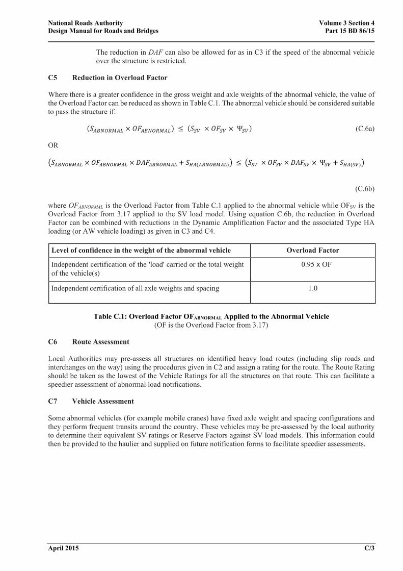
C5 Reduction in Overload Factor
Where there is a greater confidence in the gross weight and axle weights of the abnormal vehicle, the value of the Overload Factor can be reduced as shown in Table C.1. The abnormal vehicle should be considered suitable to pass the structure if:
Ψ (C.6a)
OR
Ψ
(C.6b)
where OFABNORMAL is the Overload Factor from Table C.1 applied to the abnormal vehicle while OFSV is the Overload Factor from 3.17 applied to the SV load model. Using equation C.6b, the reduction in Overload Factor can be combined with reductions in the Dynamic Amplification Factor and the associated Type HA loading (or AW vehicle loading) as given in C3 and C4.
Level of confidence in the weight of the abnormal vehicle Overload Factor
Independent certification of the 'load' carried or the total weight of the vehicle(s)
0.95 x OF
Independent certification of all axle weights and spacing 1.0
Table C.1: Overload Factor OFABNORMAL Applied to the Abnormal Vehicle (OF is the Overload Factor from 3.17)
C6 Route Assessment
Local Authorities may pre-assess all structures on identified heavy load routes (including slip roads and interchanges on the way) using the procedures given in C2 and assign a rating for the route. The Route Rating should be taken as the lowest of the Vehicle Ratings for all the structures on that route. This can facilitate a speedier assessment of abnormal load notifications.
C7 Vehicle Assessment
Some abnormal vehicles (for example mobile cranes) have fixed axle weight and spacing configurations and they perform frequent transits around the country. These vehicles may be pre-assessed by the local authority to determine their equivalent SV ratings or Reserve Factors against SV load models. This information could then be provided to the haulier and supplied on future notification forms to facilitate speedier assessments.
National Roads Authority Volume 3 Section 4 Design Manual for Roads and Bridges Part 15 BD 86/15
April 2015 C/4
C8 Example 1: Detailed Assessment
A notification for the movement of an abnormal indivisible load has been received from a haulier for moving a vehicle over a stretch of road comprising four bridges. The total weight of the vehicle is 146 tonnes and the axle weight and configuration are as shown in Figure C.1. The Reserve Factors for the four bridges is given in Table C.2.
Figure C.1: Notified Vehicle 1
Mid-span bending moments due to the abnormal vehicle and the various SV vehicles were calculated for the four bridges and multiplied by the corresponding Reserve Factors from Table C.2.
Table C.2: SV Reserve Factors for Bridges
The results are summarised in Table C.3. The partial factor, the Overload Factor and the Dynamic Amplification Factor were not included in calculating the load effects for abnormal and SV load models.
Bridge Ref.
Span (m) MABNORMAL MSV x ΨSV
SV80 SV100 SV196[AK2]
A 20 4391 5053 5196 5110
B 15 2847 3433 3417 3431
C 7.5 861 951 981 966
D 5.0 453 442 443 439
Table C.3: Mid-Span Bending Moments (kN-m) Due to abnormal and SV Load Models
From Table C.3, it can be seen that the mid-span moment due to the abnormal vehicle is less than the mid-span moment due to each of the SV load models multiplied by the corresponding Reserve Factors, i.e. equation (C.1) is satisfied for bridges A, B and C. However, this requirement is not satisfied for bridge D for which further assessment is required as considered in Example 2. The refinement given in Clause C2 (ii) was not applied as the loaded length for bridge D is less than 15m. A check was also made for the support shear and similar results were obtained.
Bridge Ref.
SV Reserve Factors, ΨSV, for Flexure
SV80 SV100 SV196[AK1]
A 1.58 1.28 1.00
B 1.54 1.21 1.04
C 1.25 1.02 1.12
D 1.28 1.01 1.13
National Roads Authority Volume 3 Section 4 Design Manual for Roads and Bridges Part 15 BD 86/15
April 2015 C/5
C9 Example 2: Regulated Movement of the abnormal load vehicle
The detailed results available from the assessment of bridge D for the SV100 load model are given in Table C.4. The load effects do not include partial factors, the Overload Factor and the Dynamic Amplification Factor.
Load Effect SHA(SV) SSV100 ΨSV100 Ψ*SV100
Moment (kN-m) 150 437 1.01 1.35
Shear (kN) 125 429 1.06 1.35
Table C.4: Detailed Assessment Results for Bridge D
The load effects due to the abnormal load vehicle and SV load models were calculated for the following three alternative measures for regulating the movement of the abnormal vehicle:
1. The abnormal vehicle passes over the bridge at a speed of less than 10mph (see C3). The comparable load effects (see equation C.3a) for the SV100 load model are given in column 3 of Table C.5.
2. The abnormal vehicle is escorted with the associated normal traffic kept clear of the bridge in all lanes (see C4). The comparable load effects (see equation C.5) for the SV100 load model are given in column 4 of Table C.5.
3. The haulier produces an independent certification of all axle loads and spacing of the abnormal vehicle. The comparable load effects (see equation C.6a) for the SV100 load model are given in column 5 of Table C.5.
Table C.5: Comparison of Abnormal Load Vehicles and SV Load Effects for Bridge D with
Alternative Management Measures
Based on the above results, it can be seen that the passage of the abnormal load vehicle over bridge D can be permitted with any one of the above three management measures.
Ionad Ghnó Gheata na
Páirce,
Stráid Gheata na Páirce, Baile Átha Cliath 8, Éire