LHC Project Document No. CERN LHC-CIB-ES-0001-00-10 CERN Div./Group or Supplier/Contractor Document No. AC/TCP EDMS Document No. 567256 Date: 17-02-2005 the Large Hadron Collider project CH-1211 Geneva 23 Switzerland Engineering Specification THE BEAM INTERLOCK SYSTEM FOR THE LHC Abstract The LHC Machine Interlock System includes Powering Interlocks and Beam Interlocks to protect the equipment of the LHC [1]. The Beam Interlock System permits beam operation. Firstly, it permits injection into the LHC when all systems are ready for beam. Secondly, with circulating beam, it transmits any beam dump request from connected systems to the beam dumping system. Prepared by: B. Puccio AB/CO R. Schmidt AB/CO B. Todd AB/CO J. Wenninger AB/OP A. Dinius AB/PO Checked by: O.Abele, R.Assmann, R.Bailey, J.C.Billy, I.Butterworth, E.Carlier, E.Ciapala, B.Dehning, R.Denz, B.Goddard, R.Losito, R.Lauckner, D.Macina, V.Montabonnet, J.Uythoven, To be approved by: S.Myers AB B.Frammery AB/CO Distribution list: TS: E. Tsesmelis, R.Saban, F.Rodriguez-Mateos, LHC: L. Evans, P.Proudlock, G.Roy, AT: K.H.Mess, AB: V.Kain, J.Lewis, K.Sigerud, R.Harrison, M.Zerlauth
CERN Div./Group or Supplier/Contractor Document No.
AC/TCP
EDMS Document No.
567256
Date: 17-02-2005
the Large Hadron Collider project
CH-1211 Geneva 23 Switzerland
Engineering Specification
THE BEAM INTERLOCK SYSTEM FOR THE LHC
Abstract The LHC Machine Interlock System includes Powering Interlocks and Beam Interlocks to protect the equipment of the LHC [1]. The Beam Interlock System permits beam operation. Firstly, it permits injection into the LHC when all systems are ready for beam. Secondly, with circulating beam, it transmits any beam dump request from connected systems to the beam dumping system.
Prepared by:
B. Puccio AB/CO R. Schmidt AB/CO
B. Todd AB/CO J. Wenninger AB/OP
A. Dinius AB/PO
Checked by:
O.Abele, R.Assmann,
R.Bailey, J.C.Billy, I.Butterworth,
E.Carlier, E.Ciapala, B.Dehning, R.Denz,
B.Goddard, R.Losito, R.Lauckner,
D.Macina, V.Montabonnet,
J.Uythoven,
To be approved by:
S.Myers AB
B.Frammery AB/CO
Distribution list: TS: E. Tsesmelis, R.Saban, F.Rodriguez-Mateos, LHC: L. Evans, P.Proudlock, G.Roy, AT: K.H.Mess, AB: V.Kain, J.Lewis, K.Sigerud, R.Harrison, M.Zerlauth
LHC Project Document No.
LHC-CIB-ES-0001-00-10
Page 2 of 26
History of Changes
Rev. No. Date Pages Description of Changes
0.1
0.2
0.3
0.4
0.5
0.6
0.7
0.8
0.9
0.10
1.0
10-05-2004
28-07-2004
10-08-2004
01-09-2005
16-09-2004
29-09-2004
01-10-2004
15-10-2004
15-11-2004
05-01-2005
17-02-2005
First draft
Second draft, user modules for each beam
With comments from B.Todd and M.Zerlauth
Modification of names
With comments from A.Dinius
With comments from R.Harrison
With comments from B.Goddard
With comments from MPWG
Injection Kickers provide user permit, height of user box
possibly 2 U, some other minor comments
New CIBU drawing 2 U. Interface to experiments changed
Starting approval in EMDS.
LHC Project Document No.
LHC-CIB-ES-0001-00-10
Page 3 of 26
Table of Contents
1. INTRODUCTION ........................................................................................5 2. PURPOSE OF THIS DOCUMENT..................................................................5 3. STRUCTURE OF THIS DOCUMENT ..............................................................5 4. MAIN OBJECTIVES OF THE BEAM INTERLOCK SYSTEM..............................5 5. DETAILED REQUIREMENTS .......................................................................6 5.1 PRODUCING BEAM_PERMIT STATUS ..........................................................7 5.2 COLLECTING INDIVIDUAL PERMIT SIGNALS FROM THE USER SYSTEMS ..........7 5.3 MASKING OF USER PERMIT SIGNALS AND SAFE BEAM FLAG .........................7
5.3.1 Masking of User Permit Signals ..................................................................................... 7 5.3.2 Safe Beam Flag ............................................................................................................... 8
5.4 PERMITTING INJECTION OF BEAM INTO THE LHC.........................................8 5.5 GENERATING BEAM DUMP REQUESTS ........................................................8
5.5.1 Required Functionality.................................................................................................... 8 5.5.2 Time between a beam dump request to a beam dump.................................................... 8
5.6 TRANSMISSION OF BEAM_PERMIT STATUS TO USER SYSTEMS......................9 5.7 MONITORING AND POST MORTEM .............................................................9 5.8 VALIDATION AND TESTS OF THE SYSTEM................................................. 10 6. ARCHITECTURE.......................................................................................10 6.1 BEAM INTERLOCK CONTROLLERS AND BEAM PERMIT LOOPS....................... 11 6.2 BEAM INTERLOCK CONTROLLER .............................................................. 12 6.3 INTERFACE TO USER SYSTEMS................................................................ 12
7. BEAM INTERLOCK CONTROLLER AND ITS INTERFACES...........................13 7.1 USERS FOR THE BEAM INTERLOCK SYSTEM .............................................. 13 7.2 INTERFACE WITH THE SPS EXTRACTION SYSTEM ...................................... 14 7.3 INTERFACE WITH THE BEAM DUMPING SYSTEM......................................... 14 7.4 INTERFACE WITH THE INJECTION KICKERS .............................................. 16 7.5 INTERFACE WITH THE SAFE BEAM FLAG ................................................... 16 7.6 INTERFACE WITH THE LHC TIMING SYSTEM ................................................. 16 8. OPERATION OF THE BEAM INTERLOCK SYSTEM......................................17 8.1 EXPLOITATION MODES OF THE BEAM INTERLOCK SYSTEM.......................... 17
8.1.1 BEAM PERMIT ........................................................................................................... 17 8.1.2 NO BEAM PERMIT..................................................................................................... 17 8.1.3 TEST MODE stand alonE ............................................................................................ 17 8.1.4 TEST MODE with the users ......................................................................................... 18
8.2 SUPERVISION FOR THE BEAM INTERLOCK SYSTEM .................................... 18 8.3 INJECTION PROCEDURES ....................................................................... 18 9. OTHER CONSTRAINTS.............................................................................19
LHC Project Document No.
LHC-CIB-ES-0001-00-10
Page 4 of 26 9.1 RELIABILITY AND AVAILABILITY .............................................................. 19 9.2 CONSTRAINTS FOR THE REALISATION ..................................................... 19 10. FUTURE SPECIFICATIONS....................................................................20 11. REFERENCES ........................................................................................20 12. APPENDIX A: LOCATION OF THE BEAM INTERLOCK CONTROLLERS .....21 13. APPENDIX B: USER SYSTEMS LIST.......................................................22 14. APPENDIX C: BEAM INTERLOCK CONTROLLER .....................................23 15. APPENDIX D: BEAM INTERLOCK USER INTERFACE...............................24 16. APPENDIX E: GLOSSARY ......................................................................25
LHC Project Document No.
LHC-CIB-ES-0001-00-10
Page 5 of 26
1. INTRODUCTION
The architecture of the LHC Machine Protection System was proposed in 2001 and documented in “Machine Protection for the LHC: Architecture of the Beam and Powering Interlock Systems” [1]. Two interlock systems were proposed:
• the Beam Interlock System, • the Powering Interlock System [2]
The requirements for the SPS extraction interlock system were defined in [3]. Since the requirements are similar as for the LHC, valuable experience was gained from using a prototype Beam Interlock Controller for the SPS extraction [4]. This specification for the LHC Beam Interlock System is based on the initial report [1], on the experience from SPS, and from the requirement that the Beam Interlock System must have a very high reliability.
2. PURPOSE OF THIS DOCUMENT
This document: • introduces the context of the LHC Beam Interlock System • gives an overview of the architecture • describes the principal functionality • specifies the performance requirements • defines the interfaces of the LHC Beam Interlock System with other systems • introduces the operational environment • introduces the constraints for the development • discusses operation, validation, documentation, reliability, availability and
maintainability. The specification will be used to build the Beam Interlock System. It defines the architecture, its operation and the interfaces to other systems. Details of how the system will be made will be published later [5].
3. STRUCTURE OF THIS DOCUMENT
In the first part of this specification the main objective for such a system in the protection of the LHC accelerators is discussed. The detailed requirements are presented together with the architecture. The interface to the users is defined. An outlook to the operation of the Beam Interlock System and its constraints are given, and the required reliability and availability are specified.
4. MAIN OBJECTIVES OF THE BEAM INTERLOCK SYSTEM
The LHC Beam Interlock System is required to operate the LHC safely with beam. Firstly, it permits injection into the LHC when all systems connected to the Beam Interlock System are ready for beam. Secondly, with circulating beam, it transmits any beam dump request from connected User Systems to the Beam Dumping System. Many User Systems have an interface to the Beam Interlock System: The Beam Dumping system, Beam Monitors, Powering Interlock Systems for superconducting and normal
LHC Project Document No.
LHC-CIB-ES-0001-00-10
Page 6 of 26
conducting magnets, Beam Cleaning System, RF system, Injection Kickers, Vacuum system, Access Safety System, SPS extraction and the LHC experiments. The main objective for the machine protection system is to protect the machine from damage in case of failure. Furthermore the system should: • Protect the beam: The system should not trigger unneccesary beam dumps. Faulty
trigger signals that lead to a beam dump should be avoided. • Provide the evidence: In case of beam dump or other failures, correct diagnostic
messages should get to the operator. For multiple alarms when one initial failure causes subsequent failures, the system should register the time sequence for the failures as they appear.
• Assist the operation of the machine: The diagnostics for failures should be easy to understand. The status of the beam interlock system must be presented clearly to the operator in the control room.
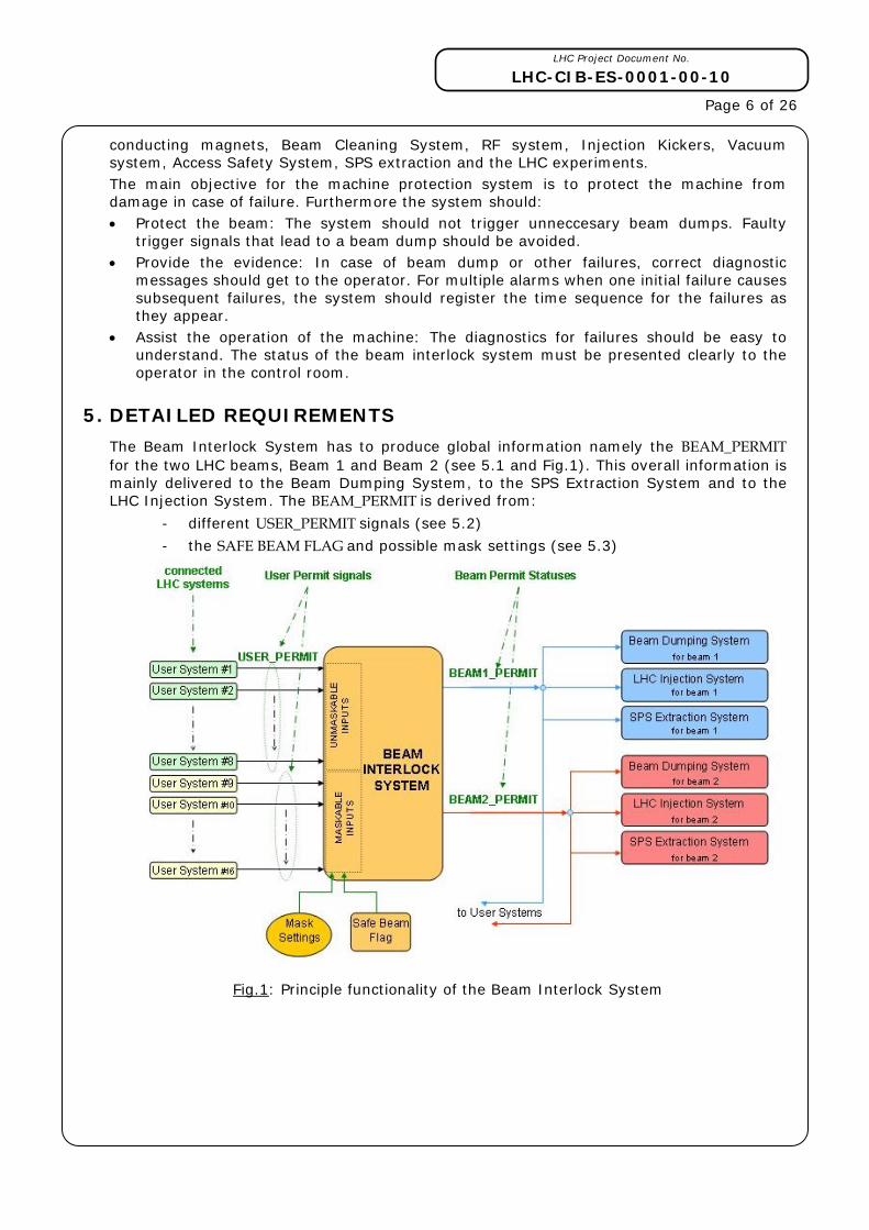
5. DETAILED REQUIREMENTS
The Beam Interlock System has to produce global information namely the BEAM_PERMIT for the two LHC beams, Beam 1 and Beam 2 (see 5.1 and Fig.1). This overall information is mainly delivered to the Beam Dumping System, to the SPS Extraction System and to the LHC Injection System. The BEAM_PERMIT is derived from:
- different USER_PERMIT signals (see 5.2)
- the SAFE BEAM FLAG and possible mask settings (see 5.3)
Fig.1: Principle functionality of the Beam Interlock System
LHC Project Document No.
LHC-CIB-ES-0001-00-10
Page 7 of 26
5.1 PRODUCING BEAM_PERMIT STATUS
BEAM_PERMIT is required for each of the two beams, and must be generated individually.
The Beam Interlock System produces for each beam one BEAM_PERMIT (BEAM1_PERMIT and BEAM2_PERMIT) and distributes theses statuses via hardware links to the Beam Dumping System and to the controls of the LHC injection kickers. In addition, this information is also distributed via hardware links to other LHC systems (see details in section 7.1) and to the SPS Extraction systems. When this specification refers to a BEAM_PERMIT without indicating beam 1 or beam 2, the explanation is valid for both statuses (for BEAM1_PERMIT and for BEAM2_PERMIT).
BEAM_PERMIT can be either TRUE or FALSE. • TRUE: the operation with the corresponding beam is permitted.
o Injection of beam is allowed. o When there is a circulating beam in the machine, the beam operation continues.
• FALSE: the operation with the corresponding beam is not permitted.
o Injection of beam is blocked. o When there is circulating beam and the BEAM_PERMIT changes from TRUE to
FALSE, the beam is extracted by the Beam Dumping system.
5.2 COLLECTING INDIVIDUAL PERMIT SIGNALS FROM THE USER SYSTEMS
The Beam Interlock System collects information from the different connected LHC systems (named User Systems in this document). The individual USER_PERMITS are then evaluated to produce the BEAM_PERMIT. User Systems are connected to the Beam Interlock System via hardware links (see 6.3). The USER_PERMIT can be either TRUE or FALSE. • TRUE: the User System is ready for beam and the beam operation is possible.
• FALSE: the connected system is either not ready for beam or has detected a failure that should result in a beam dump.
5.3 MASKING OF USER PERMIT SIGNALS AND SAFE BEAM FLAG
5.3.1 MASKING OF USER PERMIT SIGNALS
Depending on the beam intensity, energy and possibly other parameters, it is considered that signals from some User Systems could be masked. This masking is only possible if the beam is “safe” and cannot result in damaging equipment. This is defined by distributed information called SAFE BEAM FLAG (see 5.3.2).
In general, the Beam Interlock System permits beam operation in the LHC when all User Systems deliver the USER_PERMIT to the Beam Interlock System.
To allow for some flexibility while maintaining safety, the LHC systems connected to the Beam Interlock System are classified in two families: MASKABLE and NOT MASKABLE.
MASKABLE signals: The signal from the connected system that has been defined as MASKABLE, could be temporary ignored if the beam is safe. If the mask has been set by the operator, the USER_PERMIT is not taken into account to produce the BEAM_PERMIT.
NOT MASKABLE signals: if the User System is NOT MASKABLE, the USER_PERMIT will never be ignored, and has a direct influence on the BEAM_PERMIT status.
The partition MASKABLE / NOT MASKABLE is defined in Appendix B and remotely readable from the supervision of the Beam Interlock System.
LHC Project Document No.
LHC-CIB-ES-0001-00-10
Page 8 of 26 5.3.2 SAFE BEAM FLAG
The SAFE BEAM FLAG can be either TRUE or FALSE. Table 1 shows the BEAM_PERMIT as function of the SAFE BEAM FLAG and the USER_PERMITS.• TRUE (as an example, if low intensity beam is circulating at 450 GeV): The masking of
the USER_PERMIT is taken in account. If one of the masked signals is indicating FALSE, it will be ignored and beam operation can continue.
• FALSE (as an example, if the beam is accelerated and becomes unsafe due to increasing stored energy density): The masking is not longer taken in account. If any one USER_PERMIT = FALSE, then BEAM_PERMIT changes to FALSE and the beam will be dumped.
SAFE BEAM FLAG
= TRUE SAFE BEAM FLAG
= FALSE
USER_PERMIT = TRUE
TRUE TRUE
USER_PERMIT = FALSE
TRUE FALSE
Table 1: BEAM_PERMIT as a function of SAFE BEAM FLAG and USER_PERMIT. This table is valid for a User System that is maskable.
Note: The detailed definition of the SAFE BEAM FLAG and its distribution is subject of another specification.
5.4 PERMITTING INJECTION OF BEAM INTO THE LHC
The Beam Interlock System transmits the BEAM_PERMIT to the LHC injection kickers, and to the extraction kickers in the SPS. Consequently, injection of beam from the SPS into the LHC is only possible when the BEAM_PERMIT for the corresponding beam is equal to TRUE.
5.5 GENERATING BEAM DUMP REQUESTS
5.5.1 REQUIRED FUNCTIONALITY
The Beam Dumping System dumps the beam when BEAM_PERMIT changes from TRUE to FALSE. There is a Beam Dumping System for Beam 1, and a Beam Dumping System for Beam 2, both systems are independent.
5.5.2 TIME BETWEEN A BEAM DUMP REQUEST TO A BEAM DUMP
The time between the detection of the beam loss, and the moment that the beam could damage collimators is only a few turns [6]. This determines the reaction time that is required for the Beam Interlock System. There is a minimum delay between the detection of a failure and the time when all particles are extracted into the beam dump block [7]: • Some time is required for the User System to detect a failure and to send the request
to the Beam Interlock Systems in the vicinity (see chapter 6). This time can be as short as some 10 µs (e.g. for Beam Loss Monitors), but also much longer in the range of many milliseconds or even seconds. At t1: the beam dump request is detected by the Beam Interlock System.
LHC Project Document No.
LHC-CIB-ES-0001-00-10
Page 9 of 26
• The Beam Interlock System transmits the request to the Beam Dumping System. The maximum distance between a Beam Interlock controller and the beam dump is about 14 km (half-circumference of LHC). The time for a signal to travel to the Beam Dumping System is up to 70 µs. At t2: The Beam Interlock System informs the LHC Beam Dumping System in IR6.
• The synchronisation of the extraction kicker with the particle free gap takes up to one revolution (89 µs). At t3: The extraction kicker fires. It takes one turn from the start of the extraction to dump all bunches circulating in the LHC. At t4: All bunches are extracted.
Fig.2: Timescale for a beam dump (89 µs corresponds to one turn).
This determines the achievable response time of about 100 µs up to 270 µs between the detection of a beam dump request (USER_PERMIT from TRUE to FALSE) by the Beam Interlock System and the completion of a beam dump. The processing time in the Beam Interlock System should be small compared to the total time for detecting a failure and dumping the beam, say, less than 10 µs.
5.6 TRANSMISSION OF BEAM_PERMIT STATUS TO USER SYSTEMS
The BEAM_PERMIT is transmitted to the User System that might require such information. For users that distinguish between Beam 1 and Beam 2, the corresponding BEAM_PERMITS are transmitted. For users that do not distinguish between the two beams, only one status is transmitted. Whenever there might be beam in the LHC, BEAM_PERMIT = TRUE: IF BEAM1_PERMIT = FALSE AND BEAM2_PERMIT = FALSE THEN BEAM_PERMIT = FALSE
IF BEAM1_PERMIT = TRUE OR BEAM2_PERMIT = TRUE THEN BEAM_PERMIT = TRUE
5.7 MONITORING AND POST MORTEM
The Beam Interlock System must provide monitoring of all user inputs and outputs. The interface between the operators and the Beam Interlock System is via supervision programs that will present a detailed view of the status of all input signals to the operator (see section 8.2). When the beam is dumped due to a beam dump request of a Beam Interlock Controller, precise time-stamping for post-mortem information is required. The
LHC Project Document No.
LHC-CIB-ES-0001-00-10
Page 10 of 26
accuracy of the time stamps should be about 1 µs and this time should be synchronised to universal time (UTC).
5.8 VALIDATION AND TESTS OF THE SYSTEM
It is required to test the Beam Interlock System without the User Systems, for example during commissioning and validation of the system, in particular when User Systems are not ready. During such tests, it must be made sure that no beam operation is possible. Precautions need to be taken that it is not possible to enter the test mode while still operating with beam.
6. ARCHITECTURE
The Beam Interlock System is composed of 16 Beam Interlock Controllers (BICs) installed in the LHC underground areas, two in each insertion (see figure 3). One BIC will be installed right and one BIC left of each IP. Between 120 and 150 User Systems are connected to the controllers. The links between the 16 BIC’s are made via optical fibres are called BEAM PERMIT LOOPS.
Fig. 3: Architecture of the Beam Interlock System
LHC Project Document No.
LHC-CIB-ES-0001-00-10
Page 11 of 26
6.1 BEAM INTERLOCK CONTROLLERS AND BEAM PERMIT LOOPS
Each Beam Interlock Controller collects the USER_PERMITS from the connected systems installed in the vicinity. For Beam 1: The controllers are connected via two “Beam Permit Loops” (loop A and loop B). High frequency signals (10 MHz) are generated in one of the 16 BICs and sent across one loop, for example loop A, to the next BIC. Only if the necessary conditions for operation with beam 1 for this BIC are fulfilled, the signal is further transmitted to the following BIC. If this is not the case, the signal will be interrupted. Loop B is used in the same way. • The presence of the 10 MHz signal on both loops is required for BEAM1_PERMIT = TRUE. • If one of the signals is not present or has a different frequency from 10 MHz, this means
BEAM1_PERMIT = FALSE.
• If the statuses of the two loops are not identical, BEAM1_PERMIT = FALSE (see Table 2). The statuses are permitted to be different for transients due to the different transmission times in the order of 100 µs across the two loops. If the statuses are different for, say, more than 200 µs, there is a failure that needs an intervention before BEAM1_PERMIT = TRUE can be re-established. An exception is the test mode of the Beam Interlock System (see 8.1.3).
Table 2: Condition for BEAM_PERMIT STATUS (example for one beam)
Signal running clockwise (loop A)
Not present (loop opened) Present (loop closed)
Not present (loop
opened)
FALSE (Beam Interlock System in
normal condition)
FALSE (internal FAILURE or transient)
Signal
running counter
clockwise (loop B)
Present (loop
closed)
FALSE (internal FAILURE or
transient)
TRUE (Beam Interlock System in
normal condition)
For Beam 2: The systems for beam 1 and beam 2 are independent. For beam 2, the same architecture as for beam 1 is used (two loops, with a high frequency signal running clockwise / counter clockwise). When a loop is interrupted, the high frequency signal disappears. The two controllers in IR6 detect the loss of the high frequency signal, and send hardware signals to the Beam Dumping System that extracts the beam (see Fig. 3). Optical fibres will be used for the BEAM PERMIT LOOPS. The signals running clockwise and counter-clockwise ensure that the signal reaches the beam dumping system as fast as possible, and ensures redundancy. The optical fibres will only be used for the BEAM_PERMIT despite the available bandwidth, assuming that simplicity results in enhanced reliability.
LHC Project Document No.
LHC-CIB-ES-0001-00-10
Page 12 of 26
6.2 BEAM INTERLOCK CONTROLLER
A Beam Interlock Controller (BIC) is composed of: • (Beam Interlock) User Interfaces • Patching and Interface modules • Core modules • Optical Interface modules
1. The Beam Interlock User Interface collects the USER_PERMIT provided by the User System. It transmits this information to the Patching and Interface modules independently of the user hardware platform and of the distance to the User System. The Beam Interlock User Interface is installed in the user rack (see 6.3).
2. The Patching and Interface modules collect the signals coming from the different User Interfaces (up to 16). There are two set of modules (one per beam).
3. The Core module has 16 inputs for loop A, and 16 inputs for loop B (partially MASKABLE and partially NOT MASKABLE). The module is designed to perform the Interlock process via a Matrix function (done by 2 redundant matrices) and stores the I/O transition history with appropriate timing provided by the LHC Timing system. The two BEAM_PERMIT local outputs are linked to the inputs of the corresponding Fibre Optics Translator module. There are two Core modules (one per beam). The Core modules are embedded in a VME system. This front-end hardware consists mainly of a 21-slot crate with a PowerPC CPU module running under LynxOS. The CPU module includes an Ethernet interface for remote access.
4. The Optical Interface modules convert light coming over the optical fibre in current and vice-versa. There are two optical fibre loops per beam (i.e. BEAM PERMIT LOOPS). The module allows / blocks the propagation of the 10 MHz signal over the fibre optics loops. In addition, the module checks also the presence of the received signal. There are two Optical Interface modules (one per beam).
The block diagram of the Beam Interlock Controller block is shown in Annex C. It is open if the Core Module and the Optical Interface Module could be combined into one module. Note: Details on the Beam Interlock Controller are given in a separate engineering specification [5].
6.3 INTERFACE TO USER SYSTEMS
6.3.1 INTRODUCTION
The User Systems connected to the BIC’s are using different types of hardware (VME, C-PCI, PLC…). They are installed around the LHC, either in underground areas, or in surface buildings. The distance between BIC and User Systems is between several metres and several hundred metres. In order to be independent of the user hardware platform and of the distance to the user, an interface is supplied. For each connection, a Beam Interlock User Interface is provided and will be installed in the User System’s rack. This unit receives the USER_PERMIT coming from any type of LHC system. The module converts this information and transmits it to the BIC crate. Some users will always provide the USER_PERMIT for both beams. If there is a failure, both beams will be dumped. Some users will dump beam selectively, either Beam 1 or Beam 2. As each Beam Interlock Controller knows the BEAM_PERMIT STATUSES, the status for each beam will be provided for the User Systems via the Beam Interlock User Interface. In addition, the Beam Interlock User Interface includes some internal self-test parts to be remotely tested via the connected Beam Interlock Controller.
LHC Project Document No.
LHC-CIB-ES-0001-00-10
Page 13 of 26 6.3.2 HARDWARE DESCRIPTION
The Beam Interlock User Interface is installed in the user’s rack as a mountable module. It has the standard width of 19” and a height of 2U. There is a unique version serving either User Systems providing two USER_PERMIT signals (one per beam) or User Systems providing only one USER_PERMIT signal (for both beams).
The User System’s should provide a current to this interface box using either +5 Volts (if “standard” TTL electronic is used) or a +24 Volts (for PLC based system). To be failsafe, the signal must always be present to get the beam permit at the connected controller: • Current circulating in the opto-coupler input is equivalent to USER_PERMIT = TRUE.
• No current circulating is USER_PERMIT = FALSE.
The minimum value for the current flowing in the input stage is around 12mA. If the value is less than this threshold, then USER_PERMIT = FALSE. The minimum length of the signal to generate a beam dump when USER_PERMIT = TRUE changes to USER_PERMIT = FALSE is 2 µs. If the signal goes from TRUE to FALSE for shorter than 2 µs, it will be ignored. Detailed information on the User Interface and user requirements are described in a dedicated note [9]. Drawings of the front and rear views are given in Appendix D.
7. BEAM INTERLOCK CONTROLLER AND ITS INTERFACES
7.1 USERS FOR THE BEAM INTERLOCK SYSTEM
For the time being, it is assumed that the Beam Interlock Controllers receives signals from each of the following User System in the vicinity (other users can be included in the future): • Powering Interlock Controllers for superconducting magnets: each controller sends
two signals to the BIC, one (as NOT MASKABLE) for the failures in electrical circuits with magnets that are essential for beam operation, and one (as MASKABLE) for failures in electrical circuits with less critical (“auxiliary”) magnets. Electrical circuits with magnets that are essential for beam operation: in all circumstances the beam would be lost if the magnet has the wrong field. For circuits with “auxiliary” magnets the beam might survive in case of failure.
• Powering Interlock Controllers for normal conducting magnets. Similar to interlock controllers for superconducting magnets. Each controller sends one signal to the Beam Interlock Controller.
• Beam Dumping System: If the beam dumping system is not ready, it must inhibit injection of beam by providing USER_PERMIT = FALSE (more details in 7.3).
• LHC experiments: The connection of the experiments to the Beam Interlock Controller is to prevent beam operation if the experiments are not ready, and to allow for an emergency beam dump. As an example, such request could be issued if the radiation in the experiments increases to a dangerous level. Injection is only possible if movable detectors (Roman pots, or the LHC-B VELO detector) are in the position far away from the beam centre (OUT position). During physics operation (defined energy for data taking, luminosity operation, with stable beams) experiments are authorised to move detectors closer to the beams. How to avoid injecting with one of the movable detectors not in “OUT” position, and how to operate safely during data taking will be a subject of another specification.
• Radio Frequency (RF): A signal from the RF system is required to permit beam operation [10].
LHC Project Document No.
LHC-CIB-ES-0001-00-10
Page 14 of 26
• Transverse feedback: A failure of the transverse damper might cause a beam loss within a very short time. An incorrect operation of the transverse feedback must trigger a beam dump.
• Beam Loss Monitors: There will be many BLMs distributed around the ring. In the insertions, close to the collimators and to other aperture restriction, there is one set of BLMs with a response time of less than 100 µs. These BLMs are essential for protection against damage due to beam losses (“critical” monitors). In the arcs, close to each quadrupole, another set of monitors is installed (“less critical” monitors). Each controller sends two signals to the Beam Interlock Controller, one (as NOT MASKABLE) for the critical monitor that are essential for beam operation, and one (as MASKABLE) for “less critical” monitors.
• Access Safety System: The system for safety of personnel needs to follow legal requirements, independent from equipment protection. There is a direct link from the Access System to the Beam Dumping System. For redundancy, a USER_PERMIT is transmitted from the Access Safety System to the Beam Interlock System.
• Vacuum system: There will be many valves that could obstruct the beam passage. If a valve is in a position defined as “not open”, there is no beam permit. The vacuum system will read the BEAM_PERMIT, and only close a valve if it is equal to FALSE.
• Input from the beam dilutors and collimators: collimators and beam dilutors must be in the correct position for each phase of the operation. Only if the conditions are correct, do such devices give beam permit to the Beam Interlock System [11]. Details need to be specified in the future.
• Input from the system to generate and distribute Safe LHC Parameters. • Other users will be specified in a future version of this specification. Examples for
such users are beam aperture kickers, fast beam excursion monitors and fast beam current decay monitoring.
7.2 INTERFACE WITH THE SPS EXTRACTION SYSTEM
In order to extract beam from the SPS via one of the transfer lines to the LHC, the interlock system for beam extraction from the SPS requires the following information: For extraction of beam 1 from the SPS into the transfer line TI2, LHC BEAM1_PERMIT = TRUE is required.
For extraction of beam 2 from the SPS into the transfer line TI8, LHC BEAM2_PERMIT = TRUE required
7.3 INTERFACE WITH THE BEAM DUMPING SYSTEM
Before beam is injected, each Beam Dumping System must provide a permit signal for the corresponding beam to the Beam Interlock Controllers in IR6 when it is ready. The Beam Dumping System is therefore one user that provides a USER_PERMIT to the Beam Interlock System. When its USER_PERMIT = TRUE, the Beam Dumping System is ready to dump the beam. This signal is always required to establish BEAM_PERMIT = TRUE and cannot be masked.
When the BEAM_PERMIT becomes FALSE, the corresponding beam must be dumped. This is the most critical function of the Beam Interlock System.
LHC Project Document No.
LHC-CIB-ES-0001-00-10
Page 15 of 26
Fig. 4: Interface between Beam Interlock System and Beam Dumping System for Beam 1
For beam 1: The BEAM_PERMIT is transmitted to the Beam Dumping System by BIC-6L and in BIC-6R (see Fig.4). In each BIC the BEAM_PERMIT is available twice, from the loop A and from the loop B. Option to be explored: For reasons of redundancy, and to minimise the probability for a common mode failure, all four signals are routed to the beam dumping system for beam 1. Only if all BEAM_PERMIT are equal to TRUE, beam operation can continue. If one or more change from TRUE to FALSE, the corresponding beam is dumped.
For beam 2: identical to beam 1, see Fig.5. Note: Depending on further studies on reliability/availability, both beams could be dumped if one of the two BEAM_PERMIT changes to FALSE. It is proposed to define a flag called “DUMP BOTH BEAM”. When the flag is set to TRUE, the two Beam Dumping Systems are triggered by the Beam Interlock Controllers in IR6. The generation and the implementation of this additional information are subject to further discussions.
LHC Project Document No.
LHC-CIB-ES-0001-00-10
Page 16 of 26
Fig. 5: Interface between Beam Interlock System and Beam Dumping System for Beam 2
7.4 INTERFACE WITH THE INJECTION KICKERS
Each BEAM_PERMIT is distributed via hardware links to the corresponding injection kicker system (in IR2 for Beam 1 and in IR8 for Beam 2). If BEAM_PERMIT = TRUE: the beam injection is permitted.
If BEAM_PERMIT = FALSE: the beam injection is not permitted.
USER_PERMIT from the injection kickers is required for the corresponding beam, for example, for tests of the injection kickers to avoid interference with beam operation.
7.5 INTERFACE WITH THE SAFE BEAM FLAG
The SAFE BEAM FLAG is provided by the system for the generation and distribution of safe LHC Parameters specified elsewhere. When the SAFE BEAM FLAG = TRUE, masking of signals is possible. The SAFE BEAM FLAG is distributed around the LHC to each Beam Interlock Controller. When the flag is not present i.e. BEAM Flag = FALSE, or the cable carrying the signal is disconnected, masking is ignored and all USER_PERMIT signals must be = TRUE for beam operation.
7.6 INTERFACE WITH THE LHC TIMING SYSTEM
There are two types of interfaces with the Timing system: • One to get precise time stamping at the Beam Interlock Controller level. • One to provoke the generation of a Timing event that is further broadcasted to the
User Systems around the LHC.
LHC Project Document No.
LHC-CIB-ES-0001-00-10
Page 17 of 26
a) Every BIC has an internal buffer using to store the I/O transition history. A BIC is connected to the LHC Timing system in order to get a precise time stamping required for Post-Mortem analysis. In each Beam Interlock Controller crate, a timing receiver board (named CTRP) is installed. This board receives timing messages, decodes them and delivers a 1PPS (one Pulse Per Second) signal to the Core module. This accurate TTL signal is used to update its internal Universal Time Clock (UTC) register. With this feature, the internal Post-Mortem buffer is time stamped with one microsecond accuracy.
b) One BIC has to be linked to the LHC Timing generator (CBCM) to provoke the generation of a “Post-Mortem event”. The Beam Interlock Controllers are distributed around the LHC and each one knows the BEAM_PERMIT statuses. In case of beam dump, the nearest controller will be used to send a trigger signal the LHC Timing generator. Then, the LHC Timing generator will broadcast this information to the other LHC systems via the Timing network as a “Post-Mortem event”. Note: The hardware interface between the BIC and the CBCM is not yet defined.
8. OPERATION OF THE BEAM INTERLOCK SYSTEM
8.1 EXPLOITATION MODES OF THE BEAM INTERLOCK SYSTEM
The modes of the LHC Beam Interlock System (see fig.6) for each of the two LHC beams are:
• OPERATION o BEAM PERMIT o NO BEAM PERMIT
• TEST
8.1.1 BEAM PERMIT
If BEAM_PERMIT = TRUE for one of the LHC beams, extraction of this beam from the SPS and subsequent transfer and injection into the LHC is permitted, provided that SPS extraction interlocks and transfer line interlocks give permission. When the beam permit disappears (transition from TRUE to FALSE), this beam is dumped by the Beam Dumping System.
8.1.2 NO BEAM PERMIT
If BEAM_PERMIT = FALSE for one of the LHC beams, injection of this beam is inhibited. In this mode there should never be circulating beam in the LHC, since the transition from TRUE to FALSE should always dump the beam before. Since it takes some time to transmit the signals to the SPS extraction and LHC injection, there is a dead time of about 100 µs: when the beam dump fires, injection will be disable only after such dead time.
8.1.3 TEST MODE STAND ALONE
There is a test mode for each of the beams. In this mode it shall not be possible to give general beam permit. It is possible to close only one of the two BEAM PERMIT LOOPS for each beam in test mode:
• The Beam Interlock User Interface sets the USER_PERMIT = TRUE for one of the two redundant branches. This is done for all users, and for each Beam Interlock Controller.
• This will enable the 10 MHz signal circulating in one BEAM PERMIT LOOP.
• In this mode the second loop will be forced to remain open. It must never be possible to close both loops in test mode at the same time.
LHC Project Document No.
LHC-CIB-ES-0001-00-10
Page 18 of 26
The test mode facilitates verification of the complete functioning, and permits long term tests of the Beam Interlock System without the risk of giving accidental beam permit.
8.1.4 TEST MODE WITH THE USERS
The final validation of the system must be done together with the users. Assume that a user provides USER_PERMIT = TRUE when the system is ready for beam. On request, each user should be able to provoke a change from USER_PERMIT = TRUE to USER_PERMIT = FALSE.
Fig.6: Exploitation Modes Flowchart
8.2 SUPERVISION FOR THE BEAM INTERLOCK SYSTEM
The most relevant information from the Beam Interlock System to be displayed in the control room is the BEAM_PERMIT for each beam. The supervision for the Beam Interlock System will also read and display the status of all USER_PERMIT’s for each Beam Interlock Controller, as well as the output status. The supervision will allow masking for some of the channels. The status of the hardware will be displayed, showing for example, which channels are disabled. All state changes and the associated time stamps that are recorded in the controllers will be read and archived via the supervision. In addition, the supervision provides the interface to the logging, alarm and post-mortem systems.
8.3 INJECTION PROCEDURES
During injection of high intensity beam there is a risk that equipment in the LHC is not in a correct state. A procedure for injection has been defined in [12]. An Engineering Specification is in preparation that discusses interlocking between LHC and SPS.
LHC Project Document No.
LHC-CIB-ES-0001-00-10
Page 19 of 26
9. OTHER CONSTRAINTS
9.1 RELIABILITY AND AVAILABILITY
The Beam Interlock System requires a study of the reliability and availability. The study will use some of the methods defined by the norm IEC 61508. This norm is the most appropriate norm, as it is used for safety critical systems and is recognised by external authorities. The architecture of the system must ensure the performances, in terms of reliability and availability, the functions of safty systems according to the Safety Integrity Level – SIL. A full analysis of the expected reliability and availability can only be performed after the system is designed. However, during the design some principles are already being applied: • No simple failure of a component in the systems must bring the system into a non safe
state (see also IEC 61508-2). • The system must be « fail-safe » (all failures of the system must bring the LHC in a
safe state that is BEAM_PERMIT = FALSE).
• The Beam Interlock System must be available when the LHC operates with beam, or is preparing for operation with beam.
• The lifetime of the system is estimated at 20 years. • If the redundancy in the Beam Interlock System is lost, it must be detected and
repaired in order to come back to the required SIL level. • Failures that do not result in a loss of functionality (for example of the monitoring part
of the system) must lead to maintenance procedure. The maintenance must be done before the next “mission” (before the next fill), in order to come back to the required SIL level.
Informing the Beam Dumping System about a change of the BEAM_PERMIT is the most critical function of the Beam Interlock System, and this function must be executed with the highest reliability (SIL3 or SIL4). The Beam Dumping System must inform the Beam Interlock Controllers of its status, this function is critical and must be executed with SIL3. Informing other systems on the BEAM_PERMIT is less critical, and this function must be executed with SIL2.
9.2 CONSTRAINTS FOR THE REALISATION
• The system should not be affected by an electrical pertubation. The system will be connected to the Uninterruptible Power Supply (UPS) system. Reading out of the data in case of power failure must be possible in less than 8 min.
• The long distances and the large number of signals must be taken into account for the architecture and the transmission.
• The planning and the requirements for the installation and validation must be met. The systems must be finally validated during hardware commissioning.
• Standard LHC naming conventions should be used (see appendix E).
LHC Project Document No.
LHC-CIB-ES-0001-00-10
Page 20 of 26
10. FUTURE SPECIFICATIONS AND TECHNICAL NOTES
• Generation and distribution of Safe LHC Parameters (SAFE BEAM FLAGS, BEAM PRESENCE FLAGS, energy and possibly other parameters)
• Definition of a Safe Beam (what beam intensity at what energy) • Interlocking between SPS, LHC, CNGS and transfer lines • Interface of the Beam Interlock System and the LHC Beam Dumping System • Interface between machine interlocks and experiments • Interface between BIC and Timing System to provide post mortem trigger • Reliability and Availability studies on the Beam Interlock System
11. REFERENCES
[1] F.Bordry et al., The Architecture of the Machine Protection System of the LHC, LHC Project Report 521 [2] B.Puccio & R. Schmidt, Powering Subsectors, Functional Specification: LHC-D-ES-0002 [EDMS Document No. 361532] [3] R.Giachino, B.Puccio, R.Schmidt, J.Wenninger, Architecture of the SPS beam and extraction interlock systems, CERN-AB-2003-010-OP, Geneva, CERN, May 2003 [4] A.Dinius et al., Beam Interlocks for LHC and SPS, 9th International Conference on Accelerator and Large Experimental Physics Control Systems ICALEPCS 2003, Gyeongju, Korea, 13 - 17 Oct 2003 [5] B.Puccio, The Beam Interlock Controller Engineering Specification, in preparation [6] R.Schmidt et al., Beam loss scenarios and strategies for machine protection at the LHC, HALO ’03, Montauk, NY, 19-23 May 2003 [7] B.Puccio, Interlock Channels and their Timescales, Workshop of LHC performance Chamonix-12, Chamonix, France, 3 - 8 Mar 2003 [8] R.Filippini et al., Reliability Issues of the LHC Beam Dumping System, EPAC 2004 [9] B.Todd et al. The User Interface for Beam Interlock System. Technical note, in preparation [10] E.Shaposhnikova, S.Fartoukh and B.Jeanneret, LHC abort gap filling by proton beam, EPAC 2004 [11] R.Assmann et al., An Improved Collimation System for the LHC, EPAC 2004 [12] R.Schmidt and J.Wenninger, LHC Injection Scenarios, LHC-PROJECT-NOTE-287
LHC Project Document No.
LHC-CIB-ES-0001-00-10
Page 21 of 26
12. APPENDIX A: LOCATION OF THE BEAM INTERLOCK CONTROLLERS
Name of the underground
area
Rack Name with the Beam Interlock
Controller
Usual name of the Beam Interlock
Controller
Name of the Beam Interlock Controller
(LHC Naming Convention)
US15 CYCIB01 BIC-R1 CIBC.R1
US15 CYCIB02 BIC-L1 CIBC.L1
UA23 CYCIB01 BIC-R2 CIBC.R2
UA27 CYCIB01 BIC-L2 CIBC.L2
UJ33 CYCIB01 BIC-R3 CIBC.R3
UJ33 CYCIB02 BIC-L3 CIBC.L3
UA43 CYCIB01 BIC-R4 CIBC.R4
UA47 CYCIB01 BIC-L4 CIBC.L4
USC55 CYCIB01 BIC-R5 CIBC.R5
UJ56 CYCIB01 BIC-L5 CIBC.L5
US63 CYCIB01 BIC-R6 CIBC.R6
US67 CYCIB01 BIC-L6 CIBC.L6
UJ76 CYCIB01 BIC-R7 CIBC.R7
UJ76 CYCIB02 BIC-L7 CIBC.L7
UA83 CYCIB01 BIC-R8 CIBC.R8
UA87 CYCIB01 BIC-L8 CIBC.L8
LHC Project Document No.
LHC-CIB-ES-0001-00-10
Page 22 of 26
13. APPENDIX B: USER SYSTEMS LIST
family Main Beam Interlock Users: USER_PERMIT signal on: Beam Loss Monitors at aperture limitations
BEAM_PERMIT: Overall information produced by the Beam Interlock System.
There are two BEAM_PERMIT’s (one per beam, BEAM1_PERMIT and BEAM2_PERMIT). The information is delivered to the corresponding Beam Dumping System, to the corresponding Injection system and the corresponding SPS extraction system. In addition, it is distributed to the User Systems. The BEAM_PERMIT can be either TRUE (operation with the corresponding beam is permitted) or FALSE (if there is no beam: the injection is blocked. If there is circulating beam: the beam is extracted by the Beam Dumping system).
USER_PERMIT: Specific information produced by a User System connected to a Beam Interlock Controller. The USER_PERMIT can be either TRUE (ready for beam and beam operation possible) or FALSE (the system is either not ready for beam or has detected a failure).
SAFE BEAM FLAG: Distributed information generated by a dedicated system (not yet defined). The parameters to produce it will be defined in a future specification. The information is delivered all around the LHC to the different controllers composing the Beam Interlock System. The SAFE BEAM FLAG can be either TRUE (USER_PERMIT masking is taken in account) or FALSE (the masking is ignored).
MASK SETTING: Action that allows the disabling (via the supervision) of some USER_PERMIT SIGNALS. Depending on the beam intensity, energy and possibly other parameters, it is considered that some USER_PERMITS could be masked. This masking is only possible if the user system has been classified as MASKABLE and if the SAFE BEAM FLAG = TRUE.
(BEAM INTERLOCK) USER SYSTEM: LHC system connected to Beam Interlock System via the Beam Interface User Interface unit. The User System should provide a permanent signal in order to keep their “green light” for beam operation. The signal is named USER_PERMIT. There are families of User System: MASKABLE and NOT MASKABLE. The partition has been previously defined and is fixed by hardware settings.
(BEAM INTERLOCK) USER INTERFACE: Hardware unit provided by the Controls group and installed in the User System rack.
This small unit (48 x 4 x 3 cm) collects the USER_PERMIT independently of the user electronics and of the distance to the interlock system. The unit is remotely powered and linked to Beam Interlock Controller via copper cable. In addition, the module delivers to the User System the signals corresponding to BEAM_PERMIT.
LHC Project Document No.
LHC-CIB-ES-0001-00-10
Page 26 of 26
BEAM INTERLOCK CONTROLLER (i.e. BIC): Hardware units embedded in a VME crate.
It is composed mainly of a Core module performing the Interlock process via 2 redundant matrices and producing BEAM_PERMIT. This signal is transmitted over the BEAM_PERMIT LOOPS to the next BIC by an Optical Interface module.
Sixteen Beam Interlock Controllers are installed all around the LHC.
BEAM PERMIT LOOPS: Name of fibre optics that is linking the 16 Beam Interlock Controllers. There are 2 fibre optics links per beam. They are used to transmit a high frequency signal (10MHz) that corresponds to the BEAM_PERMIT. In order to optimise the propagation time to the IP6, the signal is transmitted clockwise on one loop and anti-clockwise on the other one. The presence of the signal on both loops is required for BEAM_PERMIT = TRUE.
In the following table a naming convention for the signals used in this specification is proposed.
Name Shortname used in this specification
Values Comments
B1:STATUS_PERMIT B2:STATUS_PERMIT
BEAM1_PERMIT BEAM2_PERMIT
true, false Only if TRUE, operation with B1/B2 permitted
BEAM_PERMIT true, false Generic name for BEAM1_PERMIT
BEAM2_PERMIT
RF.B1:STATUS_PERMIT (example for name)
true, false Only if TRUE, beam 1 permission from RF is given
BLM.B1B2:STATUS_PERMIT (example for name)
true, false Only if TRUE, beam permission for each beam from BLM is given
USER_PERMIT true, false Generic name for STATUS_PERMIT from any user