THE BEHAVioR oF SinglE-SHAFT ComBinED CYClE gAS TURBinE UniTS AT FREqUEnCY DRop
in THE ConnECTED gRiD
ViKToR SilBERmAnnEngineering consultant, Fichtner Consulting Company, Germany.
ABSTRACTin the last 15 years many companies have developed single-shaft combined cycle gas turbine (CCgT) units having one generator, which is coupled to common single shaft of gas turbine (gT) and steam turbine (ST) via a special elaborated synchro-self-shifting (SSS) clutch. This clutch connects automati-cally the drive of the ST at one end of the generator to complement the drive of the gT at the other end of the generator. Such a technical solution, in comparison to previous ones, allows economizing on one generator circuit breaker (gCB) as well as the use of a two-winding transformer instead of a three-winding transformer. This scheme of single-shaft CCgT units is taking place in many coun-tries, but cases of tripping of such units by surge protection of gT have been observed in any power plants (pp). All such trippings were accompanied by frequency drop in the high voltage (HV) grid, to which these units were connected, although these drops were within the permissible limits for the CCgT units. This paper reports the results of investigating one of these cases of tripping, discusses the possible cause of these incidents and elaborates on some measures to prevent such trippings in the future.Keywords: CCGT unit, disturbances in the HV grid, frequency drop, SSS clutch, steam turbine acceleration, surge protection, water pumps’ drives.
1 inTRoDUCTionmany power plants (pps) in various countries are being operated with combined cycle gas turbine units (CCgT units). From the very beginning, such units consisted of gas turbine (gT), heat recovery steam generator (HRSg), steam turbine (ST) and two generators being coupled with a gT shaft and an ST shaft. Both generators are connected to a high voltage (HV) network via two generator circuit breakers (gCBs) and one three-winding transformer.
in the last 15 years many companies have developed single-shaft CCgT units having one generator, which is coupled to common single shaft of gT and ST via a special elaborated synchro-self-shifting (SSS) clutch. This clutch connects automatically the drive of the ST at one end of the generator to complement the drive of the gT at the other end of the generator. Such a technical solution, in comparison to previous ones, allows economizing on one gen-erator circuit breaker (gCB) as well as the use of a two-winding transformer instead of a three-winding transformer.
An increase in the number of trippings of single-shaft CCgT units by surge protec-tion of gT have been observed in many countries in the last ten years [1]. many of these trippings were accompanied with a frequency drop in the HV grid, to which these units were connected, although the frequency values were within the permissible limits for the gT and ST (about 49 Hz). one of these trippings has been investigated with the author’s participation in the investigation, and the results of this investigation are presented for discussion.
238 V. Silbermann, Int. J. of Energy Prod. & Mgmt., Vol. 3, No. 3 (2018)
2 DESCRipTion oF pREVioUS TRippingS oF THE SinglE-SHAFT CCgT UniT
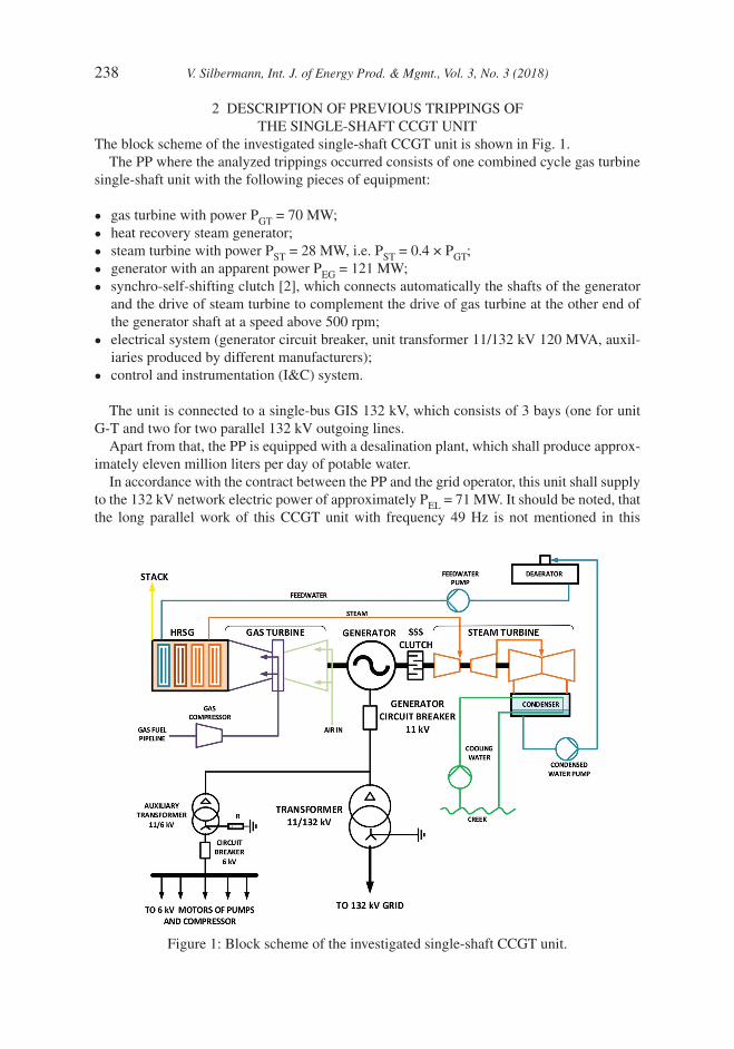
The block scheme of the investigated single-shaft CCgT unit is shown in Fig. 1.The pp where the analyzed trippings occurred consists of one combined cycle gas turbine
single-shaft unit with the following pieces of equipment:
• gas turbine with power pgT = 70 mw;
• heat recovery steam generator;
• steam turbine with power pST = 28 mw, i.e. pST = 0.4 × pgT;
• generator with an apparent power pEg = 121 mw;
• synchro-self-shifting clutch [2], which connects automatically the shafts of the generator and the drive of steam turbine to complement the drive of gas turbine at the other end of the generator shaft at a speed above 500 rpm;
• electrical system (generator circuit breaker, unit transformer 11/132 kV 120 mVA, auxil-iaries produced by different manufacturers);
• control and instrumentation (i&C) system.
The unit is connected to a single-bus giS 132 kV, which consists of 3 bays (one for unit g-T and two for two parallel 132 kV outgoing lines.
Apart from that, the pp is equipped with a desalination plant, which shall produce approx-imately eleven million liters per day of potable water.
in accordance with the contract between the pp and the grid operator, this unit shall supply to the 132 kV network electric power of approximately pEl = 71 mw. it should be noted, that the long parallel work of this CCgT unit with frequency 49 Hz is not mentioned in this
Figure 1: Block scheme of the investigated single-shaft CCgT unit.
V. Silbermann, Int. J. of Energy Prod. & Mgmt., Vol. 3, No. 3 (2018) 239
contract. Consequently, the behavior of different pieces of equipment, which have essential influence on the stable functioning of the one-shaft CCgT unit (e.g. gas compressors or water pumps), has not been analyzed at the frequency of about 49 Hz.
Since the starting day of its commercial operation, the gas turbine has suffered from rotor and compressor surge problems.
After four months of operation, the gT tripped for the first time on surge protection. The grid frequency at this time was remarkably low (49.1 Hz). However, it was well within the design operation limit of 49–51 Hz.
Following the advice of the manufacturing company, besides several checks, the preven-tive exchange of the inlet guide vane (igV) position sensor was performed and the power island was back on base load.
on the 2nd day after putting of operation, the gT tripped for the second time on surge protection. The grid frequency again was low (49.2 Hz).
The performed borescopic turbine inspections showed no damages.The fact finding mission performed by the manufacturing company identified a compres-
sor deration raising the surge line closer to the actual operation speed of 2952 rpm at 49.2 Hz.The igV position sensor was replaced again and the power island was synchronized to
the grid.on the 3rd day after having been put into operation, the gT tripped for the third time on
surge protection under frequency drop.Borescopic turbine inspections showed no damages again.Following the company’s recommendations, several i&C settings have been modified, namely
• the cooling air valve started opening when frequency started to decrease;
• the flue gas over temperature control (oTC) setting was reduced;
• the polygon governing the reasonable igV closing ratio was re-calculated.
These modifications seemed to be successful, however, the base load output of the power island was reduced from net 80 mwEl to net 71 mwEl.
3 DESCRipTion oF THE inVESTigATED TRipon the 14th day after last putting into operation, the fourth gT trip on surge protection occurred caused by heavy grid disturbances (occurrence of short circuit and tripping of one of 132 kV parallel lines by off operation of second line). The gT parameters recorded during this trip are shown in Fig. 2.
The actual grid frequency drop rate of 6.7 Hz/s exceeded the maximal design drop rate of 1 Hz/s significantly. As follows from the recorded data submitted by the pp (see Fig. 2), the stepwise increase of power at the common shaft of turbines and generator (at single shaft of unit) from 76.5 mw to 92.5 mw within 130 ms after this disturbance in the grid led to the trip of the whole unit by surge protection of the gas turbine. As a result of this increase of turbine power, the turbine governor began to reduce the turbine speed, but this reduction was made to the value 47.75 Hz only in the idle mode after the tripping of the generator circuit breaker as a consequence of the gas turbine trip. Unfortunately, the record-ings in all protection relays have not been used by this investigation since they were inaccessible, that is, deleted after three months and could not provide help during the following investigation.
After the trip, the gT was opened, and the rotor was pulled by the company for further investigations.
240 V. Silbermann, Int. J. of Energy Prod. & Mgmt., Vol. 3, No. 3 (2018)
in contrast to the results of the borescopic inspections previously performed, the inspection of the gT revealed an extended number of damages on the 3rd row stage vanes of the compressor.
The complete diaphragm 3 was replaced as well as in total, 16 stationary blade vanes all over the compressor and the turbine end bearing.
All rotor blades and vanes have been polished and additional i&C equipment has been installed, namely
• a thyristor-controlled plug & play module for the igV actuator providing faster igV clos-ing to avoid compressor overload;
• a SipRoTEC 7VE6 multifunction paralleling device providing quicker isolation of the power island from grid in case of frequency disturbances exceeding the design range (48–52 Hz).
in addition, a modified gT washing schedule was introduced to avoid the accumulation of deposits, which was the main cause of the surge in company’s opinion.
The power island went back to the base load.However, to recover at least some of the power output losses caused by the modifications
regarding the 3rd surge effect the i&C performed settings have been partially set back to the initial figures.
However, in a bid of the pp to get an independent analysis, the last trip has been investi-gated once more with the participation of the author’s consultancy firm in the investigation.
4 inFlUEnCE oF THE ElECTRiCAl pART – DiSCUSSionConsidering that all previous surge trippings have been accompanied by a network frequency drop of around 49 Hz, the author’s consultancy team confirmed the results of the company’s
Figure 2: The parameters of gT in single-shaft CCgT unit recorded during the investigated trip.
V. Silbermann, Int. J. of Energy Prod. & Mgmt., Vol. 3, No. 3 (2018) 241
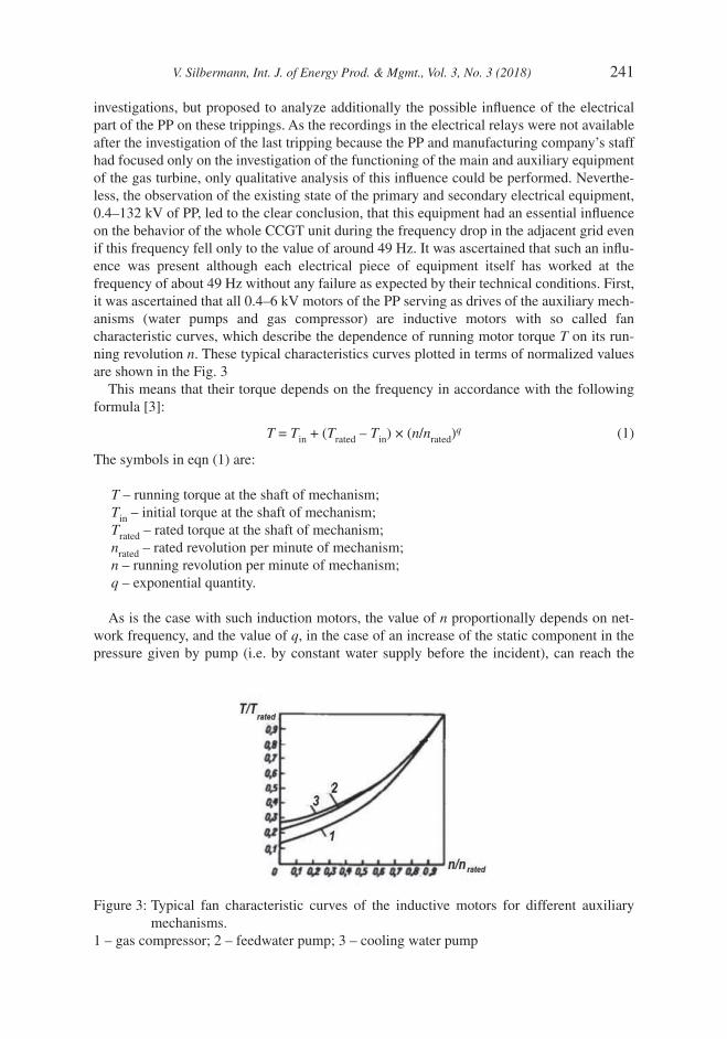
investigations, but proposed to analyze additionally the possible influence of the electrical part of the pp on these trippings. As the recordings in the electrical relays were not available after the investigation of the last tripping because the pp and manufacturing company’s staff had focused only on the investigation of the functioning of the main and auxiliary equipment of the gas turbine, only qualitative analysis of this influence could be performed. neverthe-less, the observation of the existing state of the primary and secondary electrical equipment, 0.4–132 kV of pp, led to the clear conclusion, that this equipment had an essential influence on the behavior of the whole CCgT unit during the frequency drop in the adjacent grid even if this frequency fell only to the value of around 49 Hz. it was ascertained that such an influ-ence was present although each electrical piece of equipment itself has worked at the frequency of about 49 Hz without any failure as expected by their technical conditions. First, it was ascertained that all 0.4–6 kV motors of the pp serving as drives of the auxiliary mech-anisms (water pumps and gas compressor) are inductive motors with so called fan characteristic curves, which describe the dependence of running motor torque T on its run-ning revolution n. These typical characteristics curves plotted in terms of normalized values are shown in the Fig. 3
This means that their torque depends on the frequency in accordance with the following formula [3]:
T = Tin + (Trated – Tin) × (n/nrated)q (1)
The symbols in eqn (1) are:
T – running torque at the shaft of mechanism;Tin – initial torque at the shaft of mechanism;Trated – rated torque at the shaft of mechanism;nrated – rated revolution per minute of mechanism;n – running revolution per minute of mechanism;q – exponential quantity.
As is the case with such induction motors, the value of n proportionally depends on net-work frequency, and the value of q, in the case of an increase of the static component in the pressure given by pump (i.e. by constant water supply before the incident), can reach the
Figure 3: Typical fan characteristic curves of the inductive motors for different auxiliary mechanisms.
1 – gas compressor; 2 – feedwater pump; 3 – cooling water pump
242 V. Silbermann, Int. J. of Energy Prod. & Mgmt., Vol. 3, No. 3 (2018)
values 5–6 [4]; thus, the torque on the shaft of corresponding mechanism at the frequency of about 49 Hz can be reduced to (0.85–0.9) of Trated. Such a reduction in T of all induction motors leads to a decrease in volumes of both gas that comes into gT via gas compressor (see the corresponding recorded parameter in Fig. 2) and the water that comes into the boiler via feedwater pump. By the increased load at common shaft during this incident (92.5 mw), the decrease of coming gas volume causes the breakage of the gT. Considering that in accord-ance with the data of recorders (see Fig. 2), the temperature of outlet gas has not changed during the incident, the decrease in the volume of the water that comes into the boiler should lead to a corresponding decrease of steam production (reduction of volume of produced superheat steam) in this boiler. Considering the superheated steam in HRSg as a kind of a gas, one can write in accordance with Clapeyron law [5]:
p × V = r × TK (2)
Here the meaning of the symbols is
p – gas pressure;V – volume of gas (steam);TK – absolute temperature of gas (steam);r – constant for gas (steam).
This means that the decrease in the feedwater leads to an increase in the steam pressure in the boiler and on ST inlet and as consequence in the acceleration of steam turbine. Such simultaneous breakage of gas turbine and acceleration of steam turbine, which are connected with each other via the common shaft leads to the surge (disruption of the gas flow through the turbine) in gas turbine and should cause pickup of the gas turbine surge protection. Here-with it should be additionally considered that CCgT units are normally designed so that the steam turbine shall be overtaking the gas turbine and the steam turbine power equals one third of the gas turbine power. But at this CCgT unit, the power of steam turbine is 0.4 of gas turbine power. Because of this, the same acceleration of the steam turbine in comparison with that of a steam turbine with lower mass will have a more essential impact on the behavior of gas turbine.
of course, this peculiarity of the single-shaft CCgT units brought to light by the qualita-tive analysis above (the possibility of the gT surge protection operation during frequency drop in the adjected grid) shall be simulated and confirmed quantitively by CCgT manufac-turers as well and it needs additional discussion.
5 poSSiBlE mEASURES To pREVEnT THE SURgE TRipping – DiSCUSSionAs it may be concluded from the above analysis, the following measures can be proposed to prevent possible breakdowns in the functioning of the CCgT because of weak spots in the primary equipment:
1. The motors serving the feeding pumps and the gas compressor shall be equipped with flywheels to prevent the decrease of torque during a frequency reduction in the adjacent network. The necessary parameters of flywheels and new conditions of start of these motors shall be defined additionally for concrete single-shaft CCgT units.
2. The optimal relationship of the gas and steam turbines powers in single-shaft CCgT units shall be additionally clarified in simulations mentioned in clause 4.
V. Silbermann, Int. J. of Energy Prod. & Mgmt., Vol. 3, No. 3 (2018) 243
3. Depending on the results of simulations mentioned in clause 4, the characteristics of turbine regulators shall be corrected to prevent the inadmissible acceleration of the steam turbine towards the gas turbine.
4. one additional TC/ip station bus with corresponding gateway and protocol iEC 61850-8 should be performed at each single-shaft CCgT unit. All microprocessor relays at the pp should be connected to this bus to receive from their built-in event and disturbance recorders the information during possible disturbances in the HV grid and auxiliary networks of the pp.
6 ConClUSionS1. The qualitative analysis of one trip of one single-shaft CCgT unit by surge protec-
tion operation of its gas turbine brought to light one peculiarity of such CCgT units at frequency drop in the connected grid – the strong possibility that this frequency drop can lead to a surge in the gas turbine of this unit and the operation of its surge protection even if the value of this drop lies within permissible range for each piece of such single-shaft CCgT unit.
2. This possibility can lead to the breakdown of such CCgT units and damage of their gas turbines.
3. The installation of flywheels in motors serving the feeding pumps and gas compres-sor of single-shaft CCgT unit can be recommended as a minimum measure to prevent such damages.
4. other measures for exclusion of such possible damages of single-shaft CCgT units are proposed in this paper for discussion.
REFEREnCES [1] granovskii, m. & Safonov, m., new integrated scheme of the closed gas-turbine cycle
with synthesis gas production. Chemical Engineering Science, 58(17), pp. 3913–3921, 2003.
[2] Klocke, m., Kulig, S. & Zimmer g., Modellierung and Simulation einer selbstsyn-chronisierenden Schaltkupplung in Einwellenanlagen. Elektrisch-mechanische Antriebssysteme, Tagungsband, 6–7 october, 2004 in Fulda. S. 50–55, 2004.
[3] Fitzgerald, A.E., Kingsley, C. & Umans, S.D., Electric Machinery, 7th edn., mcgraw-Hill Higher Education: new York, 2013.
[4] Korogodsky, V.i., Kuzhekov, S.l. & paperno l.B., Relay Protection of Motors with Voltages Upper 1 kV, moscow, Energoatomizdat, 1987. (in Russian).