Abstract This paper assesses the vulnerability to progressive collapse of an old and representative twelve-storey reinforced concrete (RC) framed structure, designed forty years ago for Braila according to the provisions of the Romanian Design Codes P13-70 (1970) and STAS 8000-67 (1967). The progressive collapse potential is assessed using a linear static procedure by applying damage scenarios specified in the GSA 2003 Guidelines. The results reveal that the structure has a low potential to progressive collapse based on its flexural resistance. The sensibility to shear of the old RC structure is carefully investigated and the design shear capacities are compared to experimental values furnished by static and dynamic tests. Keywords: progressive collapse, reinforced concrete framed structure, linear static procedure, damage scenarios, GSA 2003 Guidelines, demand-capacity-ratios, expected shear capacity. 1 Introduction Progressive collapse is defined by the GSA 2003 Guidelines [1] as a “situation where a local failure of a primary structural component leads to the collapse of adjoining members which, in turn, leads to additional collapse”. The damage, disproportionate to the original cause is due to the abnormal loads produced by natural hazard (e.g. earthquakes) or by man-made hazard (e.g. terrorist attacks, impact by vehicles, bomb blast, etc). These loads are not considered in the ordinary structural design.
The well-known progressive collapse cases of the Ronan Point Building (England, 1968), the Murrah Federal Building (Oklahoma City, USA, 1995) and, most important, the World Trade Center (New York City, USA, 2001) have shown the disastrous consequences of this type of structural failure. Therefore, the design philosophy of structures subjected to abnormal loads is to mitigate the risk for
Paper 243 The Behaviour of an Old Representative Reinforced Concrete Building subjected to Abnormal Loads A.G. Marchis, T.S. Moldovan and A.M. Ioani Department of Structural Mechanics Technical University of Cluj-Napoca, Romania
progressive collapse. Two major US guidelines, published by GSA (GSA 2003 [1]) and DoD (DoD 2005 [2] and DoD 2009 [3]) provide an independent methodology for minimizing the potential to progressive collapse in buildings. Both documents recommend the use of the Alternative Path Method to establish if alternative loads paths could develop when a vertical support is instantaneously removed from the structure as a result of abnormal loading.
Many studies [4, 5, 6, 7, 8, 9] using as a support the GSA 2003 Guidelines [1] have investigated the risk for progressive collapse of RC framed structures designed for different seismic areas when subjected to abnormal loads. Ioani [6] has shown that a typically medium-rise RC framed building seismically designed for a zone of high seismic risk from Romania according to the present regulations, does not experience progressive collapse when subjected to the removal of an exterior or interior column as defined by the GSA criteria.
The main objective of this paper is to investigate the risk for progressive collapse of a 40 years old and representative building of 12 storeys, when subjected to abnormal loads. In Romania, during the last 40 years, the provisions of the seismic code as well as of the design code for concrete structures have changed significantly. For instance, the structure was designed according to the older Romanian Seismic Code P13-70 [10] for a seismic base force S = 0.0567G, while the current Seismic Design Code SR EN 1998-1-2004 (EC-8) [11] requires that the building should be designed for a higher (almost twice) seismic base force S = 0.115G. P13-70 [10] contains a number of provisions much more permissive than those of the current seismic code [11]. Also, in the design and detailing of beams, the old standard for concrete structures STAS 8000-67 [12] uses a completely different method to estimate the shear capacity of beams and has accepted materials (concrete, reinforcing bars) with lower strength and ductility properties.
Taking into account these aspects, but also the fact that the analysed structure was erected in a zone with high seismic risk (ag=0.24g) and has experienced the effects of four major earthquakes, the suspicion of the designers that this type of building could have a high potential to progressive collapse when subjected to abnormal loading, seems to be justified. For these reasons and under these circumstances, the paper examines the vulnerability to progressive collapse of the building and tries to conclude if this type of structure seismically designed 40 years ago (hundreds are still in service), satisfies the present acceptance criteria given in the progressive collapse analysis [1].
2 Structural characteristics The structure consists of five 6.0 m bays in the longitudinal direction and two 6.0 m bays in the transverse direction, and has 12 storeys. The total height of the building is 34.7 m of which the typical floor-to-floor height is 2.75 m and of the first two storeys is 3.6 m. The structural components of the actual building are presented in Table 1.
Dead load is composed by the self-weight of structure and non-structural elements (walls), a supplementary variable dead load (1.65 kN/m2 on the first floor,
3
1.05 kN/m2 for the roof and 1.35 kN/m2 for current floors). Live load is taken as 4.0 kN/m2 on the first floor (commercial spaces) and 2.0 kN/m2 for the rest of them.
Structural
components Level Transverse direction Longitudinal direction
The 12-storey RC framed structure is modeled as a 3-D linear elastic model (Figure 1) using the FEA computer program SAP 2000.
Figure 1: SAP 2000 model for the 12-storey RC framed structure
4
3 Linear static procedure Following the GSA 2003 Guidelines [1] the potential to progressive collapse is assessed considering the loss of a vertical support in the so called “missing column” scenarios as illustrated in Figure 2: a) Case C1: loss of an exterior column located near to the middle of the short side; b) Case C2: loss of an exterior column located near to the middle of the long side; c) Case C3: loss of a column located at the corner of the building; d) Case C4: loss of an interior column.
Figure 2: “Missing column” scenarios according to the GSA 2003 Guidelines
A linear static analysis is used to assess the potential to progressive collapse of the existing building. Following the step-by-step procedure [1], a vertical load is applied downward to the structure under investigation:
Load = 2(DL+0.25LL) (1)
where: DL = dead load; LL = live load; In the GSA criteria, live load is reduced to 25% of the full design live load,
admitting that the entire LL value is less probable. At the same time, by multiplying the load combination by a factor of two, the GSA 2003 Guidelines [1] take into account – in a simplified approach – the dynamic effect that occurs when a vertical support is instantaneously removed from the structure; demands (QUD) in structural components are determined in terms of moments, axial forces, shear forces, etc [13].
5
Working with the results given by the linear elastic analysis (moment, shear, axial force), engineers shall identify the magnitude and distribution of potential areas of inelastic demands and thus, they will quantify the potential collapse areas. The magnitude and distribution of these demands are indicated by the DCR values (Demand-Capacity-Ratios). For each structural component or connection, DCR values are determined as follows: DCR = QUD/QCE (2) where:
QUD = acting force determined in member or connection (moment, axial force, shear or combined forces), using the linear static analysis. QCE = expected ultimate un-factored capacity of the member or connection in terms of moment, axial force, shear or combined forces, where the characteristic material strength are incresead by a strength increase factor of 1.25, both for concrete and steel bars [1].
Using the DCR criteria of the linear elastic approach, structural elements and
connections that have DCR values that exceed the allowable value are considered to be severely damaged or collapsed [1]. The allowable value for typical structural configurations is DCR ≤ 2.0 [1].
The GSA 2003 Guidelines [1] admits an allowable collapse area which is based on the structural bay size. The allowable extent of collapse resulting from the instantaneous removal of an exterior column will be taken as the smallest area from the structural bays directly associated with the removed column in the floor level above or 1800 feet2 (≈167 m2). In the case of removing an interior column, the allowable extent of collapse will be taken as the smallest area from the structural bays also associated to the removed column or 3600 feet2 (≈334 m2).
4 Seismic design of the building The building was designed in 1972 and erected in 1974 in Braila (Romania), a zone with high seismic risk; the seismic design is made following the provisions of the standard P13-70 [10], and detailing of beams and columns according to the Romanian standard for concrete structures STAS 8000-67 [12]. During its existence, the building was “in-situ tested” by four major earthquakes, as follows: 1977 Earthquake with a magnitude of M = 7.5, 1986 with M = 7.1, 30 May 1990 with M = 6.9 and 31 May 1990 with M = 6.4, where M is the earthquake magnitude on Richter scale. Since 1986 the building has been seismically instrumented and its structural response has been closely monitored. According to P13-70 [10], the Special Combination of loads used in the seismic design was: DL+0.8LL+E (3) where:
6
DL = dead load; LL = live load; E = earthquake effect.
According to the old Standard P13-70 [10], Braila is situated in the zone 8 of seismic risk with ks = 0.08. For the Romanian territory the seismic coefficient ks varies from 0.03 to 0.12. The magnitude of the total equivalent seismic force S corresponding to load combination given by Equation (3), is calculated as follows, and leads to:
S = ks · βr · Ψ · εr · G = 0.0576 G (4)
where, G is the total weight of the structure. If the building would have been designed according to the current code SR EN 1998-1-2004 (EC-8) [11], a much higher (almost twice) seismic force S would result:
S = Sd(T1) ·m· λ = agr · γI ·s ·q75.2
· gG ·λ = 0.115 G (5)
where, G is the total weight of the structure. Regarding the Special Combination of loads, the present seismic code [11], considers a reduced value for live loads (0.3LL instead of 0.8LL) as follows: DL+0.3LL+E (6) where:
DL = dead load; LL = live load; E = earthquake effect. It has to be underlined that the building was “in-situ tested” by those four major
earthquakes and even designed for a much lower seismic force S according to P13-70 [10], it stands with no structural damages, as different technical survey reports have indicated.
The original 1972 design project was reanalyzed, the authors discussed with the designers of the building, checked data and drawing of the original project and then redesigned the structure, including details following the provisions of the older codes P13-70 [10] and STAS 8000-67 [12]. Certain details for beams are presented in Table 2.
The structural response of the model under the Special Combination of loads and the behaviour of the damaged structure (with all four cases of the “missing column” scenarios as defined by the GSA 2003 Guidelines [1]), is determined using a 3-D linear elastic model, created in the FEA computer program SAP 2000.
7
Exterior frames
Storey Longitudinal frame* Transverse frame*
Top long. steel**
Bottom long.
steel**
Stirrups at ends**
Top long. steel**
Bottom long.
steel**
Stirrups at ends**
1, 2 1Φ22 + 3Φ25 (1.02%)
4Φ20
(0.69%)
Φ8/200
(0.17%)
4Φ25
(1.00%)
2Φ25+ 1Φ22 (0.69%)
Φ8/200
(0.17%) 3, 4,
5, 6 2Φ22+
2Φ25 (1.04%)
2Φ20+ 1Φ22 (0.61%)
Φ8/200
(0.17%)
1Φ22 + 3Φ25 (1.11%)
1Φ25+ 2Φ22
(0.75%)
Φ8/200
(0.17%) 7, 8, 9 4Φ22
(0.91%)
2Φ18+ 1Φ20 (0.49%)
Φ6/200
(0.09%)
2Φ22 + 2Φ25 (1.04%)
3Φ22
(0.68%)
Φ8/200
(0.17%) 10, 11,
12 3Φ18+
1Φ20 (0.65%)
3Φ14
(0.27%)
Φ6/200
(0.09%)
4Φ20
(0.75%)
3Φ16
(0.36%)
Φ6/200
(0.09%) Interior frames
Storey Longitudinal frame* Transverse frame*
Top long. steel**
Bottom long.
steel**
Stirrups at ends**
Top long. steel**
Bottom long.
steel**
Stirrups at ends**
1, 2 2Φ22+ 2Φ28 (1.04%)
2Φ20+ 2Φ22 (0.65%)
Φ8/200
(0.17%)
2Φ22+ 2Φ28 (0.96%)
3Φ25
(0.64%)
Φ8/200
(0.14%) 3, 4,
5, 6 1Φ22+
3Φ25 (1.11%)
1Φ16+ 3Φ18 (0.58%)
Φ8/200
(0.17%)
4Φ25
(1.18%)
3Φ22
(0.68%)
Φ8/200
(0.17%) 7, 8, 9 3Φ22+
1Φ25 (0.98%)
3Φ16
(0.36%)
Φ8/200
(0.17%)
2Φ22+ 2Φ25 (1.04%)
2Φ18+ 1Φ22 (0.53%)
Φ8/200
(0.17%) 10, 11,
12 1Φ18+
3Φ20 (0.72%)
2Φ14+ 1Φ16 (0.31%)
Φ6/200
(0.09%)
2Φ20+ 2Φ22 (0.83%)
3Φ16
(0.36%)
Φ6/200
(0.09%) *Concrete: Class B 200 according to STAS 8000-67 [12] with the design compressive strength fcd=10 N/mm2, equivalent to actual C12/15 concrete strength class **Reinforcing steel: - type PC52 for longitudinal reinforcement with the design yield strength fyd=290 N/mm2, where Φ is the bar diameter in mm and ρl is the reinforcement ratio for longitudinal reinforcement
- type OB38 for transverse reinforcement with fyd=210 N/mm2
Table 2: Reinforcing details of structural elements
8
5 Progressive collapse analysis
Using the GSA criteria, demands (QUD) in structural components (beams) are compared with their expected ultimate un-factored capacities (QCE), as shown in Equation 2. For beams, the DCR values for flexure are calculated at the column faces and are presented in figures, in brackets. 5.1 Bending moments and DCR values 5.1.1 Case C1 and C2 : exterior short and long side column cases The case C1 and C2 of “missing column” scenarios (Figure 2) are discussed in a previous paper [14]. All DCR values are bellow 2.0 and thus meet the acceptance criteria provided by GSA 2003 Guidelines [1]. The results show that the damaged structure is not expected to fail in bending and consequently the progressive collapse is not expected to occur for both cases. In other words, based on its flexural resistance, the building has a low potential for progressive collapse when subjected to the case C1 and C2 of the “missing column” scenarios. 5.1.2 Case C3 : corner column case The removal of a corner column affected the exterior transverse frame CT1 and the exterior longitudinal frame CLA, these two frames being interconnected at the removed column (Figure 2). The largest moments in beams for the “damaged” structure are developed at the first and second floor; a positive bending moment of 417.18 kNm (increased by 145% with respect to the design bending moment) and a negative bending moment of 613.05 kNm (increased by 128% with respect to the design bending moment) were obtained for the transverse frame CT1 (two bays). For the longitudinal frame CLA (five bays) the maximum positive moment is 363.01 kNm (increased by 118% with respect to the design bending moment) and the maximum negative moment is 540.58 kNm (increased by 106% with respect to the design bending moment), as illustrated in Figure 3.
The DCR values range from 0.57 to 1.19 for the transverse frame CT1, and from 1.02 to 1.96 for the longitudinal frame CLA. Due to the fact that all DCR values are above 1.0, indicating the inelastic behaviour of those beam sections, a plane failure mechanism is expected to occur for the longitudinal frame CLA. But, this frame will be sustained by the structural components of the transverse frame CT1 where most of the DCR values for flexure are bellow 1.0, indicating the elastic behaviour of these members.
For both frames, all DCR values are bellow 2.0, a generalized 3D failure mechanism does not occur in the model, and consequently the acceptance criteria specified by the GSA 2003 Guidelines [1] are fulfilled and the building has a low potential for progressive collapse.
9
CLA frame CT1 frame
Figure 3: Bending moments (kNm) and DCR values (in brackets) for the damage
case – C3
5.1.3 Case C4 : interior column case
In the technical literature, very few papers discuss the behaviour of buildings when an interior column is removed [7, 15]. After the removal of the interior column, the moment diagrams have changed, as illustrated in Figure 4.
As in the case C3, the largest moments in beams for the “damaged” structure are developed at the first floor; a positive bending moment of 609.33 kNm (increased by 257% with respect to the design bending moment) and a negative bending moment of 790.56 kNm (increased by 144% with respect to the design bending moment) were obtained for the transverse frame CT2.
10
CLB frame CT2 frame
Figure 4: Bending moments (kNm) and DCR values (in brackets) for the damage case – C4
The DCR values range from 0.87 to 1.59 for the transverse frame CT2 and from
0.97 to 1.60 for the longitudinal frame CLB. Practically, the beams from the longitudinal frame CLB have an inelastic behaviour at both ends (all DCR values are above 1.0, except one from the sixth floor which is 0.97) leading to a possible plane failure mechanism (Figure 4); the longitudinal frame is sustained by the upper parts of the transverse frame CT2 which behaves elastically (DCR<1.0).
For this case, no generalized 3D or local mechanism will occur, all DCR values for flexure are bellow 2.0, and thus the building meets the acceptance criteria provided by the GSA 2003 Guidelines [1] having a low potential for progressive collapse.
11
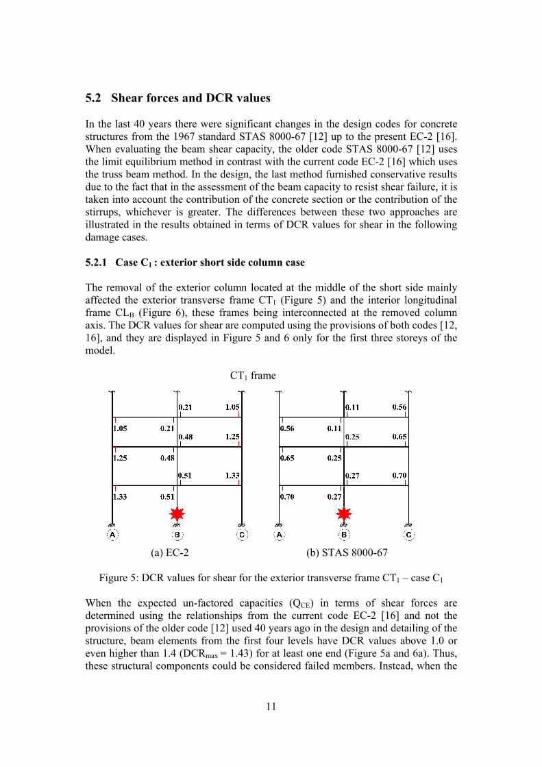
5.2 Shear forces and DCR values In the last 40 years there were significant changes in the design codes for concrete structures from the 1967 standard STAS 8000-67 [12] up to the present EC-2 [16]. When evaluating the beam shear capacity, the older code STAS 8000-67 [12] uses the limit equilibrium method in contrast with the current code EC-2 [16] which uses the truss beam method. In the design, the last method furnished conservative results due to the fact that in the assessment of the beam capacity to resist shear failure, it is taken into account the contribution of the concrete section or the contribution of the stirrups, whichever is greater. The differences between these two approaches are illustrated in the results obtained in terms of DCR values for shear in the following damage cases. 5.2.1 Case C1 : exterior short side column case The removal of the exterior column located at the middle of the short side mainly affected the exterior transverse frame CT1 (Figure 5) and the interior longitudinal frame CLB (Figure 6), these frames being interconnected at the removed column axis. The DCR values for shear are computed using the provisions of both codes [12, 16], and they are displayed in Figure 5 and 6 only for the first three storeys of the model. CT1 frame
(a) EC-2 (b) STAS 8000-67
Figure 5: DCR values for shear for the exterior transverse frame CT1 – case C1
When the expected un-factored capacities (QCE) in terms of shear forces are determined using the relationships from the current code EC-2 [16] and not the provisions of the older code [12] used 40 years ago in the design and detailing of the structure, beam elements from the first four levels have DCR values above 1.0 or even higher than 1.4 (DCRmax = 1.43) for at least one end (Figure 5a and 6a). Thus, these structural components could be considered failed members. Instead, when the
12
evaluation of the expected beam capacities (QCE) is made according to the older code [12], all DCR values for shear are well bellow 1.0 ( Figure 5b and 6b) and consequently, there are no failed members in shear (Figure 5b and 6b) and the acceptance criteria [1] are fulfilled. CLB frame
(a) EC-2 (b) STAS 8000-67
Figure 6: DCR values for shear for the interior longitudinal frame CLB – case C1 The differences in DCR values obtained by applying the relationships from these two codes [12, 16] are mainly due to the fact that the code [16] considers that when the acting shear force cannot be assumed only by the concrete, the expected un-factored capacities of the beams are assessed taking into account only the contribution of the stirrups. On the contrary, the code [12] considers the contribution of both, concrete and stirrups, when the expected un-factored capacities of the beams are evaluated. 5.2.2 Case C2 : exterior long side column case The removal of the exterior column located near the middle of the long side mainly affected the exterior longitudinal frame CLA and the interior transverse frame CT3. The longitudinal frame CLA is more affected by the loss of the vertical support due to the double spam condition of beam elements over the removed column.
As in the case C1, beam elements from the first four levels (CLA frame) have DCR values at least one end above 1.0 (DCRmax = 1.22) when the expected un-factored capacities (QCE) are calculated using the current code [16] (Figure7a). Therefore, all these elements could be considered failed members. By applying the relationships from the old code [12], the acceptance criteria (DCR ≤ 1.0) are fulfilled for all beams (Figure 7b).
Similar results (not displayed in the paper) are obtained for the structural components of the interior transverse frame CT3: beams from level 1 to level 5 could
13
be considered as failed members when using the current code [16], and there is no risk for progressive collapse by applying the provisions of the older code [12].
CLA frame
(a) EC-2 (b) STAS 8000-67
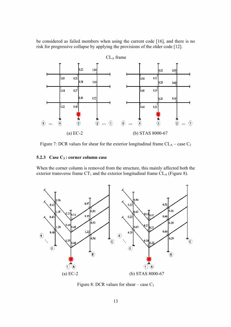
Figure 7: DCR values for shear for the exterior longitudinal frame CLA – case C2 5.2.3 Case C3 : corner column case When the corner column is removed from the structure, this mainly affected both the exterior transverse frame CT1 and the exterior longitudinal frame CLA (Figure 8).
(a) EC-2 (b) STAS 8000-67
Figure 8: DCR values for shear – case C3
14
At least at one end of beam elements from level 1 to level 4, the DCR values for shear are above 1.0 (DCRmax =1.22) when the expected un-factored capacities (QCE) are calculated using the current code [16] (Figure 8a) and therefore, these elements could be considered as failed members. By using the relationships from the old code [12], a maximum DCR value for shear of 0.64 ( Figure 8b) was obtained in the transverse beam from the first level which is well below the allowable value (1.0), and consequently the building has no risk for progressive collapse based on its shear resistance.
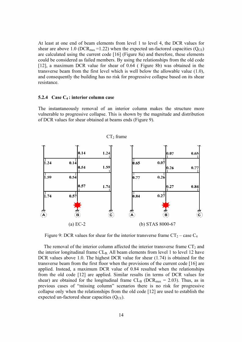
5.2.4 Case C4 : interior column case The instantaneously removal of an interior column makes the structure more vulnerable to progressive collapse. This is shown by the magnitude and distribution of DCR values for shear obtained at beams ends (Figure 9). CT2 frame
(a) EC-2 (b) STAS 8000-67
Figure 9: DCR values for shear for the interior transverse frame CT2 – case C4
The removal of the interior column affected the interior transverse frame CT2 and the interior longitudinal frame CLB. All beam elements from level 1 to level 12 have DCR values above 1.0. The highest DCR value for shear (1.74) is obtained for the transverse beam from the first floor when the provisions of the current code [16] are applied. Instead, a maximum DCR value of 0.84 resulted when the relationships from the old code [12] are applied. Similar results (in terms of DCR values for shear) are obtained for the longitudinal frame CLB (DCRmax = 2.03). Thus, as in previous cases of “missing column” scenarios there is no risk for progressive collapse only when the relationships from the old code [12] are used to establish the expected un-factored shear capacities (QCE).
15
5.2.5 Discussion on shear capacity of RC beams A final possible conclusion of the previous sections (5.2.1 to 5.2.4) could indicate that the building will collapse in shear because, for all the analyzed damage scenarios, the maximum DCR values are above the allowable value 1.0 (1.43/C1, 1.22/C2, 1.22/C3 and 2.03/C4) when the evaluation of the shear capacity is made using the provision of the active code for concrete structures EC-2 [16].
This un-expected conclusion requires an attentive analysis which involves supplementary theoretical and experimental data. The analysis is made for the first floor beam of the transverse frame CT1 which was designed according to the provisions of the old standard STAS 8000-67 [13].
During the last 40 years, the provisions of the seismic code as well as of the design codes for concrete structures have changed substantially. The seismic design according to SR EN 1998-1-1:2004 [11] leads to a seismic base force S = 0.115G (G – total weight of the building) which is almost twice the seismic force calculated according to P13-70 [10] (S = 0.0576G). While the older code [10] admits the use of the concrete type B200 (equivalent to C12/15) and reinforcement type OB38 (equivalent to S255), the current code [11] specifies a minimum concrete class C25/30 (for high ductility class) and the use of steel for reinforcement with the characteristic yield strength (fyk) between 400 and 600 N/mm2 in the critical regions of seismically designed elements. Also, the distance between stirrups is much more limited: the old code [12] specifies the use of the smallest value from {hbeam/3, 15d, 300 mm} and the current code [11] recommends the use of the smallest value from {hbeam/4, 6d, 175 mm}. Therefore, if the analyzed beam with cross section 300X700 mm would be designed to resist shear failure according to the current codes [11,16], stirrups Ф10/130 mm with fyk=500 N/mm2 (S500) and concrete class C25/30 should be used. The shear capacity of this beam (VRd = 504.02 kN) is much higher than the capacity calculated using the provisions of the old code [12]: stirrups Ф8/200 mm with fyk=260 N/mm2 (OB38) and concrete type B200 (VRd = 164.70 kN). Thus, it is understandable why, for a newly designed structure, the potential to progressive collapse of the building would be much lower.
In Table 3 are listed relationships for the assessment of the design shear capacity, and also the values obtained for the analyzed beam when the provisions of different design codes for concrete structures are applied.
The code STAS 8000-67 [12], STAS 10107/0-76 [17], STAS 10107/0-90 [18] and ACI 318-08 [19] takes into account the contribution of the stirrups and also of the concrete when the design shear capacity is calculated. Instead, the code SR EN 1992-1-1: 2004 (EC-2) [16] considers that when the acting shear force cannot be assumed only by the concrete, the design shear capacity of the section will be assess taking into account only the contribution of the stirrups. As a consequence, the design shear capacity calculated according to the current code [16] (VRd = 164.70 kN) is lower than the computed value according to the older code [12] (Qeb = 240.18 kN). Practically, the DCR values for shear do not satisfy the acceptance criteria if the expected shear capacity of the section is made according to EC-2 [16] (DCR = 1.34) and ACI 318-08 [19] (DCR = 1.35). In a theoretical and experimental program carried out by the National Institute for
16
Building Research – INCERC, Romania, results from 326 RC beams, statically loaded and tested at shear up to the failure, were analyzed [20]. The experimentally measured shear capacities (Qexp) were compared to design shear capacities (Qd), calculated according to different design codes, using design material strengths (Table 3).
Codes
Relationships for
calculating the design shear force
Design shear
force (Qd)
d
CE
QQ
d
exp
QQ
DCR for
shear
STAS 8000-
67 [12] atetei
20eb RAqR0.6bhQ −=
240.18 kN 1.88 0.90 0.70
STAS 10107/0-76 [17] aatet
e0t20
eb
RmA
)qhMQ(1pR3.2bh
Q
−
+
=
174.67 kN 1.70 1.24 1.06
STAS 10107/0-90 [18]
tRms
pbhsqQ t
i
20
ieeb +=
186.69 kN 1.68 1.16 1.01
SR EN 1992-1-1:2004
[16]
cotθzfs
AV ywdsweff
Rds =
cot Ɵ = 2.5 (Ɵ = 220)
164.70 kN 1.44 1.31 1.34
ACI
318-08 [19] s
dfAdb'f0.17λVVV
ytv
wcscn
+
=+=
ФVn = design shear force Ф=0.75
150.00 kN 1.56 1.44 1.35
Table 3: Design shear capacities and DCR values for shear obtained for the analyzed
beam, using different relationships specified by codes This extensive experimental program revealed that, by using the provisions of the code STAS 10107/0-76 [17], the ratios (Qexp/Qd) are always greater than 1.24 for 325 beams, and is 1.12, for one single beam. Accepting that a similar value of 1.24 may be applied in our analysis, the minimum real shear capacity of the analyzed beam will be greater than 174.64*1.24 = 216.50 kN. With respect to this experimental value determined under static loads, Table 3 shows that the older
17
standard [12] overestimates the shear design capacity (Qexp/Qd = 0.90), meanwhile the modern codes EC-2 [16] and especially ACI 318-08 [19] lead to conservative results (Qexp/Qd = 1.31, respectively 1.44).
Recent experimental and theoretical study [21] demonstrated that the shear capacity of RC beams increases substantially under dynamic loads. The cracking shear force increases by 88% and the shear at the first yield of the stirrups by 44% to 74%, under dynamic loads [21]. If an average dynamic increase factor of 1.5 is considered, as Fujikake determined in his paper [22], the expected real shear capacity of the section under dynamic loads should be greater than 1.5*216.50 kN = 324.70 kN. Using this value QCE = 324.70 kN, and QUD = 316 kN (resulted from linear static analysis of the damaged structure – case C1), then the maximum value for DCR is 0.98, and consequently the model has no risk for progressive collapse based on its shear resistance. Similar commentaries and conclusions may be done for the other damage scenarios (C2, C3 and C4). 6 Conclusions The present study establishes the potential to progressive collapse of an old and representative mid-rise RC framed building when subjected to abnormal loads produced by natural hazard (e.g. earthquakes) or by man-made hazard (e.g. terrorist attacks, impact by vehicles, bomb blast, etc).
The GSA 2003 Guidelines [1] provide an independent methodology to assess the potential to progressive collapse for the existing buildings. Based on the results furnished by the linear static analysis procedure, the DCR (Demand-Capacity-Ratios) values are used to identify the magnitude and distribution of potential areas of inelastic demands and thus, to quantify the potential collapse areas and compared to the allowable ones provided by the GSA criteria.
In a previous study [14], the authors have shown that this building has a low potential to progressive collapse when subjected to case C1 and C2 of the “missing column” scenarios, and its flexural response is considered.
In this paper, the investigation is continued by the analysis of the other two cases (C3 and C4), rarely presented in the technical literature.
In the case C3 (corner column removal), the largest DCR value for flexure is 1.96, very closed to the allowable value (2.0) and practically all DCR values for flexure are above 1.0, indicating large inelastic demands in the longitudinal frame beams (CLA). Due to the interconnection of the longitudinal frame with the transverse frame (CT1) which behaves elastically, the possibility of creating a generalized space (3D) mechanism is eliminated, and the building has a low potential for progressive collapse.
In the case C4 (interior column removal) the DCR values for flexure are in the range of 0.87 to 1.60. As in previous case, all DCR values for flexure determined at beams ends are above 1.0, indicating a possible plane failure mechanism of the three hinged type for the longitudinal frame (CLB). But, this frame will be sustained by the structural components with elastic behaviour (DCR<1.0) from the transverse frame (CT2). A new finding of the paper indicated that the 12-storey RC building is
18
more vulnerable to progressive collapse when an interior column is removed, and this damage scenario should not be avoided in the analysis, as many designers currently do.
The significant changes during the last 40 years in the design codes for concrete structures from the 1967 standard STAS 8000-67 [12] up to the present SR EN 1992-1-1:2004 [16] has a significant impact on the results obtained in terms of DCR values for shear, and not for flexure.
If the evaluation of the expected un-factored capacities (QCE) of beam elements is made using the provisions of the current code EC-2 [16], certain beams have at least one end DCR values for shear above 1.0, and even higher than 2.0 (case C4) in some components. As a consequence, these elements could be considered failed members and therefore the building would have a high risk for progressive collapse.
On the other hand, by applying the provisions from the old code [12] a maximum DCR value of 0.84 was obtained in the case C4 of the “missing column “ scenarios and therefore, the building fulfilled the acceptance criteria [1]. The differences in DCR values for shear obtained using the provisions from these two codes [12, 16] are mainly due to the fact that the current one [16] does not take into account in certain circumstances the contribution of the concrete to resist shear failure. The acting shear force is assumed only by the stirrups if it is lower than the shear capacity of concrete section. In Table 3, based on experimental test results, it is shown that the design shear force calculated according to the old design code [12] is slightly overestimated (Qexp/Qd = 0.90); the design shear force predicted by the current code [16] is underestimated in reasonable limits (Qexp/Qd = 1.31).
The study has shown that, in general, the RC structures, designed according to the older codes are sensitive to shear forces, but an immediate conclusion of failure in shear should be prudently regarded. In particular, the structure under investigation does not fail in shear as it was demonstrated in Section 5.2.5 using results from theoretical and experimental studies [20, 21, 22].
To conclude, the old and representative 12-storey RC framed building, designed forty years ago for a high seismic zone according to older Romanian codes P13-70 [10] and STAS 8000-67 [12], is not expected to fail in bending or shear and consequently, the progressive collapse is not expected to occurs when the building is subjected to damage scenarios provided by the GSA 2003 Guidelines [1]. This final conclusion is sustained by the in-situ behaviour of the real building which experienced without significant structural damages four severe earthquakes, including the 1977 Vrancea Earthquake (M=7.5). Acknowledgment The writers gratefully acknowledge the support from Romanian National Authority for Scientific Research (ANCS and CNCSIS-Grant PNII-IDEI No. 193/2008) for this study.
Also this paper was supported by the project "Improvement of the doctoral studies quality in engineering science for development of the knowledge based
19
society-QDOC” contract no. POSDRU/107/1.5/S/78534, project co-funded by the European Social Fund through the Sectorial Operational Program Human Resources 2007-2013.
References [1] U. S. General Services Administration, “Progressive collapse analysis and
design guidelines for new federal office buildings and major modernization projects”, Washington, DC, 2003.
[2] U. S. Department of Defense (DoD 2005), “Design of buildings to resist progressive collapse”, Unified Facility Criteria, UFC 4-023-03, Washington, DC, 2005.
[3] U. S. Department of Defense (DoD 2009), “Design of buildings to resist progressive collapse”, Unified Facility Criteria, UFC 4-023-03, Washington, DC, 2009.
[4] S. M. Baldridge, F. K. Humay, “Preventing Progressive Collapse in Concrete Buildings”, Concrete International, Vol. 25, 73-79, November, 2003.
[5] N. D. Bilow, M. Kamara, “U. S. General Services Administration Progressive Collapse Guidelines Applied to Moment – Resisting Frame Building”, 2004 ASCE Structures Congress, Nashville, Tennessee, 2004.
[6] A. M. Ioani, H. L. Cucu, C. Mircea, “Seismic design vs. Progressive Collapse: A Reinforced Concrete Framed Structure Case Study”, Proceedings of ISEC-4, Melbourne, Australia, 2007.
[7] M. H. Tsai, “Investigation of progressive collapse resistance and inelastic response for an earthquake-resistant RC building subjected to column failure”, Journal of Engineering Structures, No. 30, 3619-3628, 2008.
[8] D. Joshi, P. V. Patel, S. J. Tank, “Linear and Nonlinear Analysis for Assessment of Progressive Collapse Potential of Multistoried Building, ASCE Structures Congress, 2010.
[9] H. Kim, “Progressive Collapse Behaviour of Reinforced Concrete Structures with Deficient Details”, PhD Thesis, The University of Texas at Austin, U.S., 2006.
[10] P13-70, “Normative for designing of civil and industrial buildings from seismic areas”, Polytechnic Institute of Cluj, Cluj-Napoca, 1971 (in Romanian).
[11] SR EN 1998-1-1:2004, “Eurocode 8: Design of structures for seismic resistance – Part 1: General rules, seismic actions and rules for buildings”, ASRO, Bucharest, 2004 (in Romanian).
[12] STAS 8000-67, “Designing element of concrete, reinforced concrete and prestressed concrete”, Romanian Standard Institute, Bucharest, 1967 (in Romanian).
[13] A. Ioani, H. Cucu, “Comparative study of the potential to progressive collapse using the linear static analyses (GSA, DOD)”, Journal of the Annals of the
20
University of Oradea Magazine: Constructions and Hydroedilitary Installations, Vol.13, 169-177, 2010.
[14] A. G. Marchis, T. S. Moldovan, A. M. Ioani, “Flexural resistance of an old RC framed structure subjected to abnormal loads”, Proceedings of the 4th International Conference in Civil Engineering – Science and Practice GNP 2012, 923-930, Zabljak, Montenegro, February 20-24, 2012.
[15] D. Joshi, P.V. Patel, S.J. Tank, “Linear and Nonlinear Analysis for Assessment of Progressive Collapse Potential of Multistoried Building”, ASCE Structures Congress, 2010.
[16] SR EN 1992-1-1:2004, “Eurocode 2: Design of concrete structures – Part 1-1: General rules and rules for buildings”, ASRO, Bucharest, 2004. (in Romanian).
[17] STAS 10107/0-76, “Design and detailing of concrete, reinforced concrete and prestressed concrete structural members”, Romanian Standard Institute (IRS), Bucharest, 1976 (in Romanian).
[18] STAS 10107/0-90, “Design and detailing of concrete, reinforced concrete and prestressed concrete structural members”, Romanian Standard Institute (IRS), Bucharest, 1990 (in Romanian).
[19] ACI 318M-08, “Building Code Requirements for Structural Concrete”, American Concrete Institute, Farmington Hills, Michigan, USA, 2008.
[20] D. Dumitrescu, M. Weissenberg, M. Spînoche, I. Ban, “Recommendations for improved provisions regarding the shear capacity of reinforced concrete elements”, INCERC – Technical Report, Bucharest, 1970 (in Romanian).
[21] W.A. Keenan, “Dynamic shear strength of reinforced concrete beams”, Part I, Technical report R395, US Naval Civil Engineering Laboratory, Port Hueneme, California, 1965.
[22] K. Fujikake, B. Li, “Dynamic shear resistance of RC beams”, Proceedings of 9th International Conference on Shock & Impact Loads on Structures, Fukuoka, Japan, November, 2011.