17 Ridge Road Branchville, NJ 07826 Phone: 973-948-0226 Fax: 973-948-2562 www.behringersystems.com [email protected]® The Best Solution For Process Piping Installations Indianapolis ● Chicago ● San Juan www.hollandapt.com 800-800-8464
Indianapolis ● Chicago ● San Juan www.hollandapt.com
800-800-8464
ii Catalog CHSAN0109 WWW.BEHRINGERSYSTEMS.COM PHONE: 973-948-0226
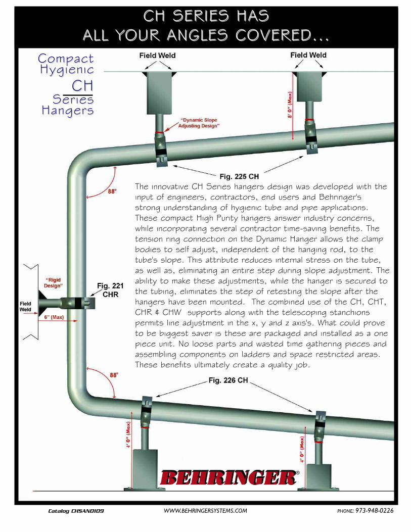
The innovative CH Series hangers design was developed with theinput of engineers, contractors, end users and Behringer'sstrong understanding of hygienic tube and pipe applications.These compact High Purity hangers answer industry concerns,while incorporating several contractor time-saving benefits. Thetension ring connection on the Dynamic Hanger allows the clampbodies to self adjust, independent of the hanging rod, to thetube's slope. This attribute reduces internal stress on the tube,as well as, eliminating an entire step during slope adjustment. Theability to make these adjustments, while the hanger is secured tothe tubing, eliminates the step of retesting the slope after thehangers have been mounted. The combined use of the CH, CHT,CHR & CHW supports along with the telescoping stanchionspermits line adjustment in the x, y and z axis's. What could proveto be biggest saver is these are packaged and installed as a onepiece unit. No loose parts and wasted time gathering pieces andassembling components on ladders and space restricted areas.These benefits ultimately create a quality job.
CH SERIES HASCH SERIES HASALL YOUR ANGLES COVERED...ALL YOUR ANGLES COVERED...
CH SeriesFig. 221 CH CH - Dynamic Mount Hanger Pages 4 - 5 CHR - Rigid Mount Hanger Pages 6 - 7CHW - Weld Plate Mount Support Pages 8 - 9 CHT - Threaded Mount Hanger Pages 10 - 11Fig. 245 - Threaded Support Rod Page 12
StanchionsFig. 223 - Telescopic Base Stand Page 13 Fig. 224 - Rod Stand Plate Page 14Fig. 225 - Telescopic Adjusting Stanchion Hang Mount Page 15Fig. 226 - Telescopic Adjusting Page 16
Stanchion Floor Mount Stand (Round or Square)
Smooth Bore SeriesFig. 200 - Smooth Bore Weld Plate Mount Page 17 Fig. 201 - Smooth Bore Hang Plate Mount Page 18 Fig. 202 - Smooth Bore Base Plate Mount Page 19Fig. 203 - Smooth Bore RAL-1 Rail Mounting Page 20Fig. 204 - Smooth Bore Stacking Kit Page 21Fig. 211 - Smooth Bore Unistrut Mount Page 22Fig. 221 - Smooth Bore Rod Mount Page 23
MiscellaneousFig. 109 - Heavy Series Anchor Clamp Page 24Fig. 251 - Sanitary Clamps Page 25Technical Data Material Properties, Pages 26-28Slope Conversion Chart, Shear Force Diagram
For more information:visit our website at www.behringersystems.comorcall our office at (973)948-0226
Hardware Material 084 = 1/2" Pipe304 S/S = T316 S/S = X Group #
Zinc Plated Carbon Steel = Z 3 = Group 36 = Group 67 = Group 77A = Group 7A8 = Group 8 (where available)9 = Group 9 (where available)
T
Smooth Bore Part # Configurator
3 100 -SPH SB
EEXAMPLEXAMPLE OORDERINGRDERING GGUIDEUIDE
Dynamic "Anchor or Guide" Slope Adjusting Hanger/ Rod Mount Unit
One piece unit with attached dynamic rod. Hanger rods are available inlengths ranging from min of 1.26" to 96". Standard length is 6”.
Features: A dynamic union between the hanger rod and hanger housingallows for the housing to self adjust to the tubes slope for drainability as wellas a 360o swivel. A 6" rod is the standard length with other lengths available.Fig 221 CH can also be used in combination with the figure 223, 225 or 226stanchions. This combination will allow the support to be adjusted telescopi-cally to the tube or pipe elevation. Call customer service for the price andavailability of special rod lengths.
Size Range: 0.24" diameters through 6.00" diameter covering imperial tube,pipe and copper sizes. ISO and DIN standards, and special diameters avail-able upon request.
Anchor "D" DimensionFor sizing refer to "D" column on dimensional chart
Round Part Number to the Hundredth 1.05 = 105
Hardware Material304 Stainless Steel = T316 Stainless Steel = X
Rigid Rod LengthStandard Length 6" = 06
12" = 1218" = 1824" = 24
Special lengths are availableUpon Request
CHR- PG- 105 – 06T-Fig. 221 CHR Compact Rigid Hanger - Part Number Configurator
Rigid “Anchor or Guide” Hanger / Rod Mount Unit
One piece unit with rod welded to the hanger housing. Hanger rods are avail-able in lengths up to 96”. Standard rod length is 6”
Features: The rigid hanger is ideal for supporting vertical runs and reducingvibrations. This type rod connection does not offer the dynamic slope adjust-ment. 6" rod is the standard length with other lengths available. Fig 221CHR can also be used in combination with the figure 223, 225 or 226 stan-chions. This combination will allow the support to be adjusted telescopicallyto the tube or pipe elevation. Call customer service for the price and avail-ability of special rod lengths.
Size Range: 0.24" diameters through 6.00" diameter covering imperialtube, pipe and copper sizes. ISO and DIN standards, and special diametersavailable upon request.
Hardware: 304 stainless steel (Standard), 316 stainless steel also available upon request
Finish: Stainless steel at a 25 RA
Plastic: Polysulfone (Black = Anchor and Gray = Guide)
Shearing: Anchors - Refer to shear force diagram in technical section(page 27)
Guides - Allows free axial movement for thermal expansion of tube or pipe
Housing withBlack insertsare "Anchor"
supports
Housing withGray insertsare "Guide"
supports
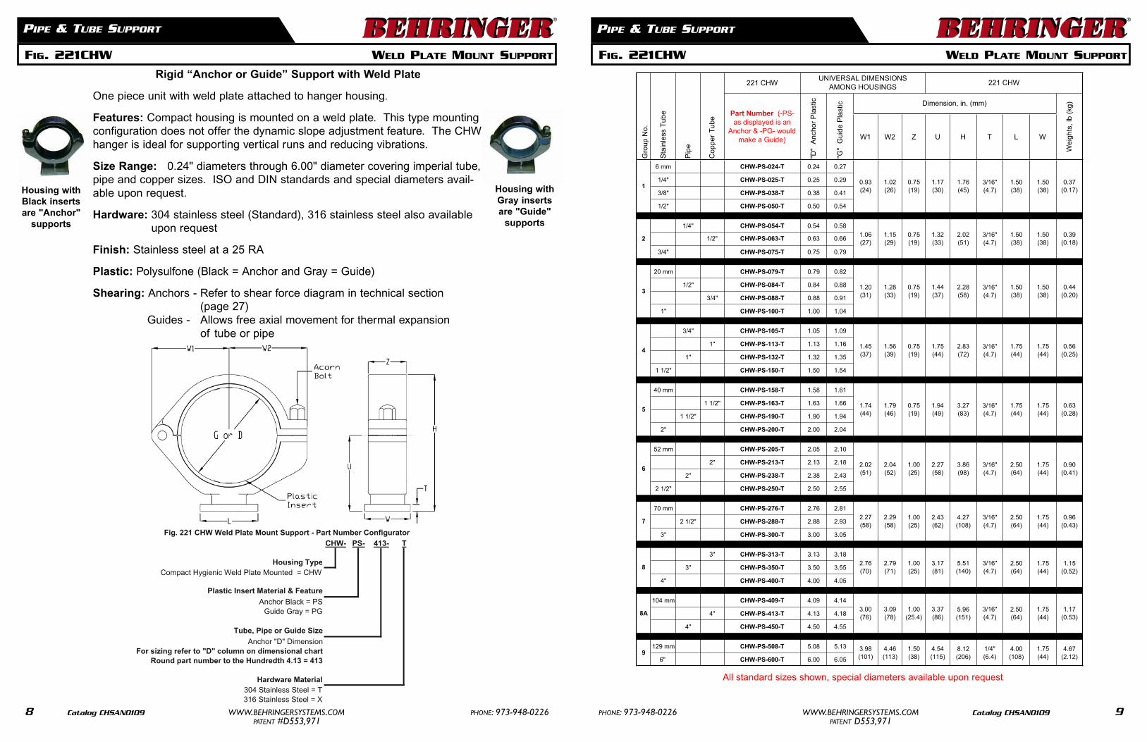
All standard sizes shown, special diameters available upon request
One piece unit with weld plate attached to hanger housing.
Features: Compact housing is mounted on a weld plate. This type mountingconfiguration does not offer the dynamic slope adjustment feature. The CHWhanger is ideal for supporting vertical runs and reducing vibrations.
Size Range: 0.24" diameters through 6.00" diameter covering imperial tube,pipe and copper sizes. ISO and DIN standards and special diameters avail-able upon request.
Plastic Insert Material & FeatureAnchor - Black = PS
Guide - Gray = PG
Tube, Pipe or Guide SizeAnchor "D" Dimension
For sizing refer to "D" column on dimensional chartRound Part Number to the Hundredth 1.50 = 150
Hardware Material304 Stainless Steel = T316 Stainless Steel = X
CHT- PG- 150 TFig. 221 CHT Compact Threaded Mount Hanger - Part Number Configurator
Threaded "Anchor or Guide" Hanger
One piece unit with threaded adaptor. Rod is sold separately
Features: The threaded mounting section, on top of housing, doubles as athreaded rod connecter and a welding platform. This type rod connectiondoes not offer the dynamic slope adjustment feature. Figure 221 CHT, with arod, can also be used in combination with the figure 223, 225 or 226 stan-chions. This combination will allow the support to be adjusted telescopicallyto the tube or pipe elevation. Call customer service for the price and avail-ability of special rod lengths.
Size Range: 0.24" diameters through 6.00" diameter covering imperial tube,pipe and copper sizes. ISO and DIN standards, and special diameters avail-able upon request.
Hardware Material Finish304 Stainless Steel = T 25 = 25Ra316 Stainless Steel = X
Carbon = CZ
Rod DiameterZinc = = 3/8"
B = 1/2"A
C = 5/8"D = 3/4"E = 1"
Fig. 245 Threaded Support Rod - Part Number Configurator-06ROD -038 -T -25-B
Size Range:
Hardware Material:
Finish:
Ordering:
Installations:
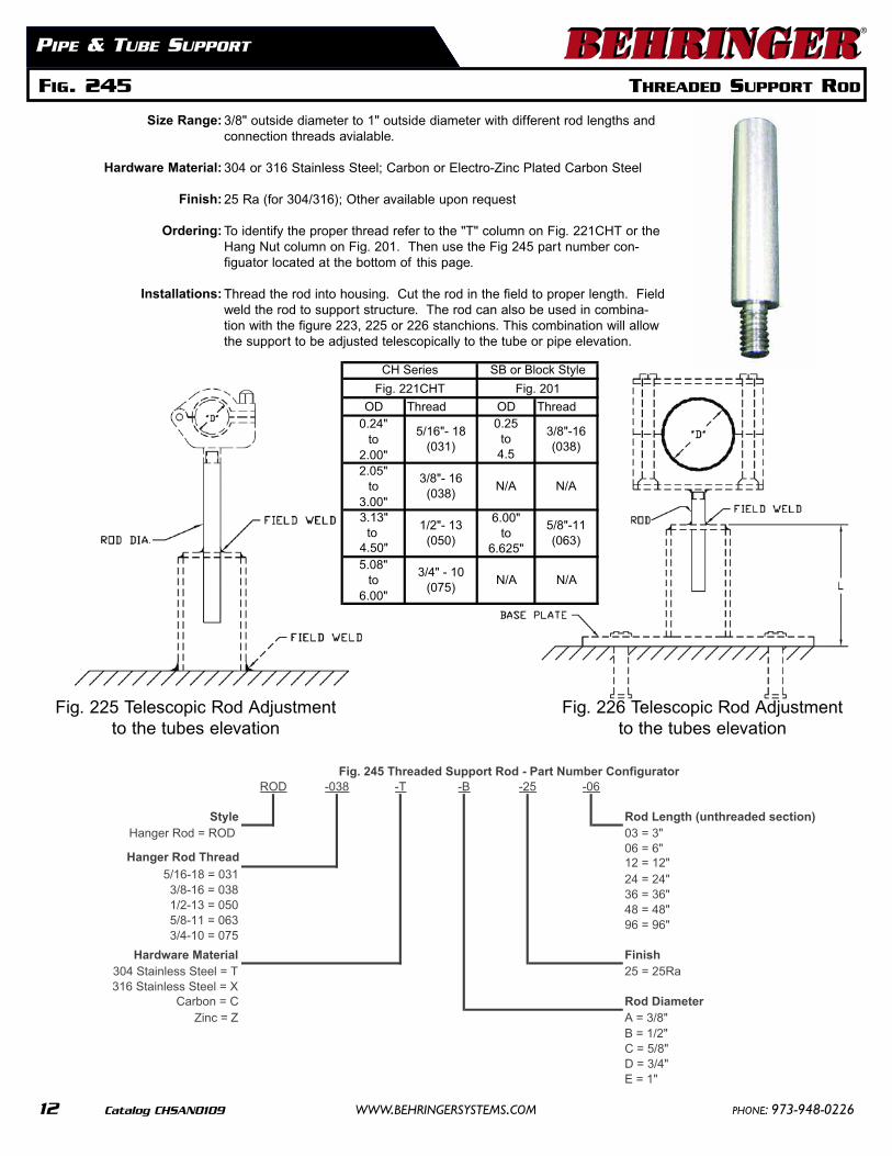
3/8" outside diameter to 1" outside diameter with different rod lengths andconnection threads avialable.
304 or 316 Stainless Steel; Carbon or Electro-Zinc Plated Carbon Steel
25 Ra (for 304/316); Other available upon request
To identify the proper thread refer to the "T" column on Fig. 221CHT or theHang Nut column on Fig. 201. Then use the Fig 245 part number con-figuator located at the bottom of this page.
Thread the rod into housing. Cut the rod in the field to proper length. Fieldweld the rod to support structure. The rod can also be used in combina-tion with the figure 223, 225 or 226 stanchions. This combination will allowthe support to be adjusted telescopically to the tube or pipe elevation.
Fig. 225 Telescopic Rod Adjustmentto the tubes elevation
Fig. 226 Telescopic Rod Adjustmentto the tubes elevation
FIG. 223 TELESCOPIC ADJUSTING ROUND FLOOR MOUNT STAND
The Telescopic Adjusting Round Floor Mount Stand allows the housing’s rod elevation tobe adjusted up to 2” from the base plate’s surface. The rod attached to the housing slidesinside the base plate’s elevation adjustment tube. This fine tune adjustment allows theinstaller to quickly change the support’s elevation to match the tube’s distance from thefloor. The base plate can be supplied with or without anchor bolt holes. Anchor bolts notsupplied by Behringer.
Base Plate Sizing:
Hardware Material:
Finish:
RSP1 & RSP2 - 0.25” to 2.00” OD tube & pipe sizesRSP3 & RSP4 - 2.05” to 4.50” OD tube & pipe sizesRSP5 & RSP6 - 5.08” to 6.00” OD tube & pipe sizes
MILL = Fabricated steel and welds are a mill finishBUFF = Fabricated steel and weld are buffed to remove splatterBLND = Fabricated steel is polished and welds are blendedSpecial finishes and painted stands are available, call Behringer
Clamp & Rod Sold Separately
Telescopic Base Stand FinishMILL = Fabricated steel and welds are a mill finish
Hardware Material BUFF = Fabricated steel and weld are buffed to remove splatter304 Stainless Steel = T BLND = Fabricated steel is polished and welds are blended
316 Stainless Steel = X SPL = Special finishes available, call BehringerElectro-Zinc plated carbon = Z
Carbon Steel = C Rod Stand Plate SizesPainted "to end users specification" = P RSP1- = 4" x 4" x 1/4" base plate with four 7/16" anchor bolt holes
RSP2- = 4" x 4" x 1/4" base plate without anchor bolt holesSupport Rod OD RSP3- = 6" x 4" x 1/4" base plate with four 7/16" anchor bolt holes
3/8" = A RSP4- = 6" x 4" x 1/4" base plate without anchor bolt holes1/2" = B RSP5- = 8" x 6" x 3/8" base plate with four 9/16" anchor bolt holes5/8" = C RSP6- = 8" x 6" x 3/8" base plate without anchor bolt holes3/4" = D
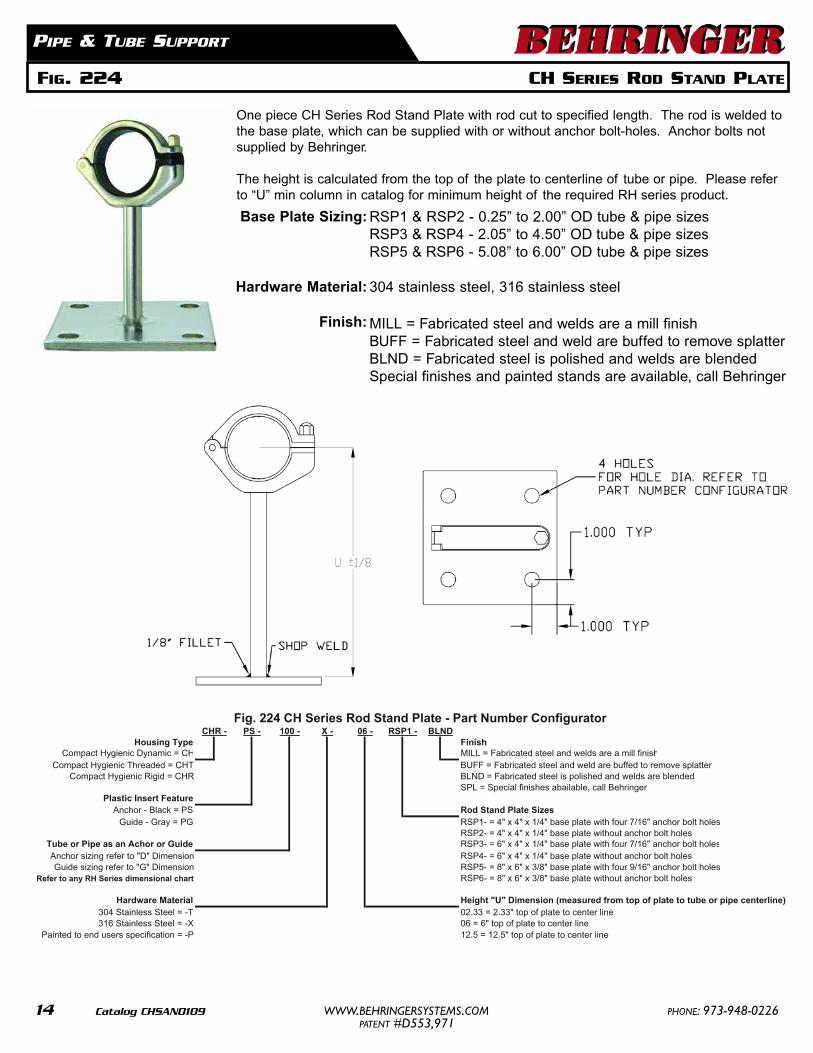
One piece CH Series Rod Stand Plate with rod cut to specified length. The rod is welded tothe base plate, which can be supplied with or without anchor bolt-holes. Anchor bolts notsupplied by Behringer.
The height is calculated from the top of the plate to centerline of tube or pipe. Please referto “U” min column in catalog for minimum height of the required RH series product.
Base Plate Sizing:
Hardware Material:
Finish:
RSP1 & RSP2 - 0.25” to 2.00” OD tube & pipe sizesRSP3 & RSP4 - 2.05” to 4.50” OD tube & pipe sizesRSP5 & RSP6 - 5.08” to 6.00” OD tube & pipe sizes
304 stainless steel, 316 stainless steel
MILL = Fabricated steel and welds are a mill finishBUFF = Fabricated steel and weld are buffed to remove splatterBLND = Fabricated steel is polished and welds are blendedSpecial finishes and painted stands are available, call Behringer
PIPE & TUBE SUPPORT
Housing Type FinishCompact Hygienic Dynamic = CH MILL = Fabricated steel and welds are a mill finish
Compact Hygienic Threaded = CHT BUFF = Fabricated steel and weld are buffed to remove splatterCompact Hygienic Rigid = CHR BLND = Fabricated steel is polished and welds are blended
SPL = Special finishes abailable, call BehringerPlastic Insert Feature
Anchor - Black = PS Rod Stand Plate SizesGuide - Gray = PG RSP1- = 4" x 4" x 1/4" base plate with four 7/16" anchor bolt holes
RSP2- = 4" x 4" x 1/4" base plate without anchor bolt holesTube or Pipe as an Achor or Guide RSP3- = 6" x 4" x 1/4" base plate with four 7/16" anchor bolt holesAnchor sizing refer to "D" Dimension RSP4- = 6" x 4" x 1/4" base plate without anchor bolt holesGuide sizing refer to "G" Dimension RSP5- = 8" x 6" x 3/8" base plate with four 9/16" anchor bolt holes
Refer to any RH Series dimensional chart RSP6- = 8" x 6" x 3/8" base plate without anchor bolt holes
Hardware Material Height "U" Dimension (measured from top of plate to tube or pipe centerline)304 Stainless Steel = -T 02.33 = 2.33" top of plate to center line316 Stainless Steel = -X 06 = 6" top of plate to center line
Painted to end users specification = -P 12.5 = 12.5" top of plate to center line
Fig. 224 CH Series Rod Stand Plate - Part Number ConfiguratorCHR - X -PS - 100 - 06 - RSP1 - BLND
Fig 225 Telescopic Hang Mount Stanchion - Part Number Configurator-XXXS12 B -SW1 -MILL-T
Hanger Stanchion with square or round tube cut to specified length. One end of thetube has a capped end with a rod hole. The rod hole is used for telescopicadjustment of the hanger rod. Specify the steel finish and the finish on the weld.
PIPE & TUBE SUPPORT
FIG. 225 TELESCOPIC ADJUSTING STANCHION - HANG MOUNT
®
Features:
Hardware:
Finish:
Hole in capped end of tube allows the hanger rod to be manuallyadjusted for telescopic location of the tube or pipe.
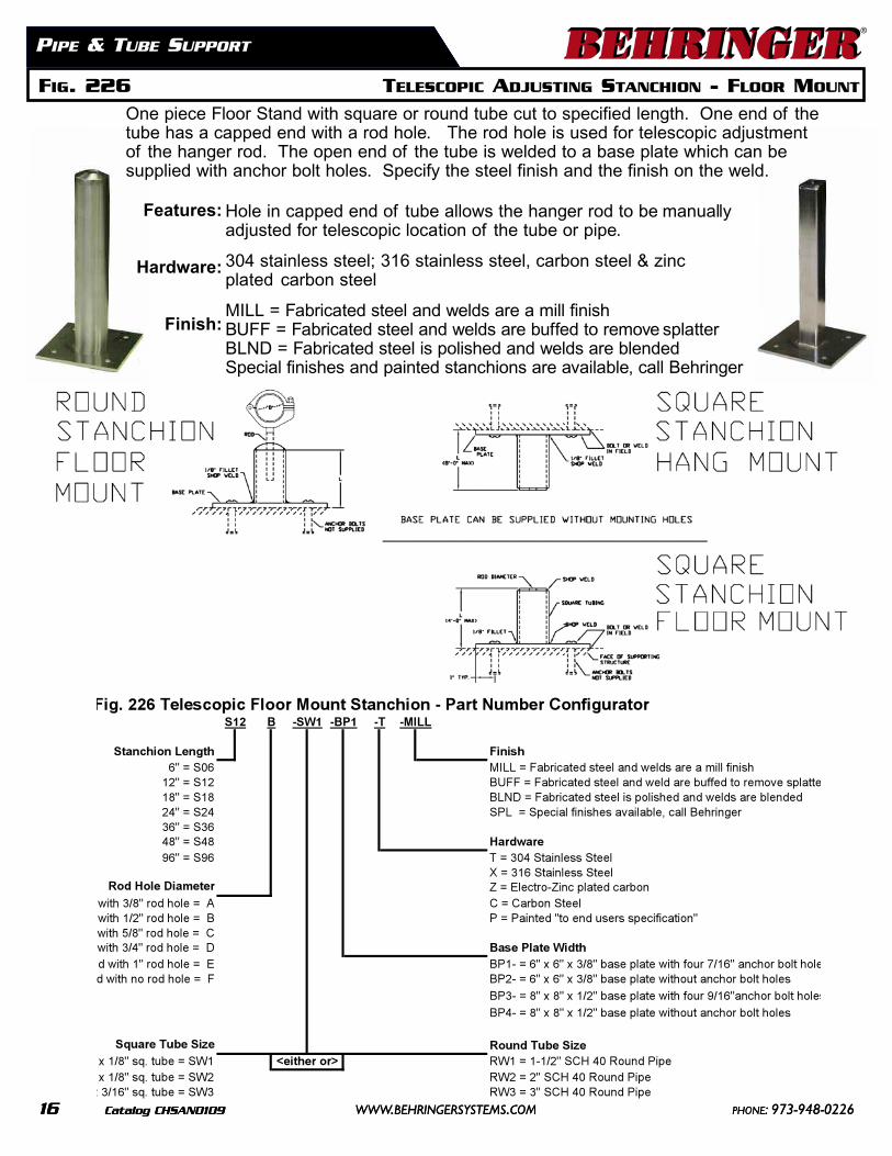
MILL = Fabricated steel and welds are a mill finishBUFF = Fabricated steel and welds are buffed to remove splatterBLND = Fabricated steel is polished and welds are blendedSpecial finishes and painted stanchions are available, call Behringer
MILL = Fabricated steel and welds are a mill finishBUFF = Fabricated steel and welds are buffed to remove splatterBLND = Fabricated steel is polished and welds are blendedSpecial finishes and painted stanchions are available, call Behringer
FIG. 226 TELESCOPIC ADJUSTING STANCHION - FLOOR MOUNT
PIPE & TUBE SUPPORT
Features:
Hardware:
Finish:
One piece Floor Stand with square or round tube cut to specified length. One end of thetube has a capped end with a rod hole. The rod hole is used for telescopic adjustmentof the hanger rod. The open end of the tube is welded to a base plate which can besupplied with anchor bolt holes. Specify the steel finish and the finish on the weld.
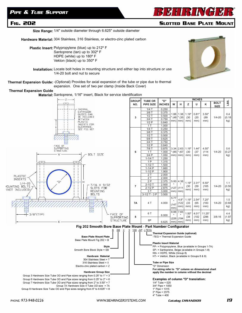
FIG. 200 BLOCK STYLE WELD PLATE MOUNT
PIPE & TUBE SUPPORT
Size Range:
Hardware Material:
Plastic Inserts:
Installations:
Thermal Expansion Guide:
Thermal Expansion Guide Material:
1/4” outside diameter through 8.625” outside diameter
304 Stainless, 316 Stainless, or electro-zinc plated carbon
Polypropylene (blue) up to 212° FSantoprene (beige) up to 302° FHDPE (white) up to 180° FVekton (black) up to 350° F
Weld bottom plate to structure or supporting member, let cool beforemounting plastic blocks.
-(Optional) Provides for axial expansion of the tube or pipe due to thermalexpansion. One set of two per clamp (Inside Back Cover)
Santoprene, 1/16" insert, Black for service identification
1/4 T 0.2503/8 T 0.3751/2 T 0.5003/4 T 0.7501/2 P 0.8401 T 1.000
1/4 T 0.2503/8 T 0.3751/2 T 0.5005/8 T 0.6253/4 T 0.7501/2 P 0.8407/8 T 0.8751 T 1.000
noisnemiD"D"3="1ot"52.0morfgnignarsezisepiPdGroup 6 Hardware Size Tube OD and Pipe sizes ranging from 0.25" to 2" = 6 For sizing refer to "D" column on dimensional charGroup 7 Hardware Size Tube OD and Pipe sizes ranging from 2" to 3.50" = 7 apply the number in column without the decimal
Group 7A Hardware Size 4 Tube OD Group 8 Hardware Size Tube OD and Pipe sizes ranging from 6" to 6.625" = 8 Examples of column "D" translation:
SP- = Santoprene, Beige (available in Groups 1-8)Hardware Material NN- = HDPE, White (available in Group 8)
)9&8spuorGnielbaliava(kcalB,notkeV=-THT=leetSsselniatS403316 Stainless Steel = X
Electro-zinc plated carbon = Z Tube or Pipe Size"D" Dimension
Hardware Group Size For sizing refer to "D" column on dimensional chartGroup 3 Hardware Size Tube OD and Pipe sizes ranging from 0.25" to 1" = 3 apply the number in column without the decimalGroup 6 Hardware Size Tube OD and Pipe sizes ranging from 0.25" to 2" = 6Group 7 Hardware Size Tube OD and Pipe sizes ranging from 2" to 3.50" = 7 Examples of column "D" translation:
Base Plate Mount Fig 202 = B Plastic Insert Material
Style PP- = Polypropylene, Blue (available in Groups 1-7A) )8-1spuorGnielbaliava(egieB,enerpotnaS=-PSBS=elytSkcolBeroBhtoomS
NN- = HDPE, White (Group 8)Hardware Material HT- = Vekton, Black (available in Groups 8 & 9)
304 Stainless Steel = T316 Stainless Steel = X Tube or Pipe Size
noisnemiD"D"Z=nobracdetalpcniz-ortcelEFor sizing refer to "D" column on dimensional chart
Hardware Group Size apply the number in column without the decimalGroup 3 Hardware Size Tube OD and Pipe sizes ranging from 0.25" to 1" = 3
Group 6 Hardware Size Tube OD and Pipe sizes ranging from 0.25" to 2" = 6 Examples of column "D" translation:520=ebuT"4/17="05.3ot"2morfgnignarsezisepiPdnaDOebuTeziSerawdraH7puorG0501=epiP"4/3A7=ezisDOebuT4eziSerawdraHA7puorG
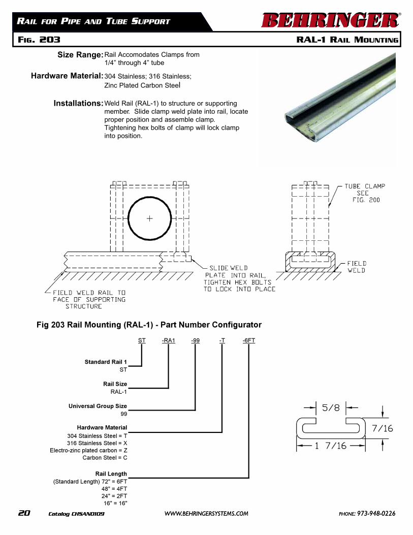
Weld Rail (RAL-1) to structure or supportingmember. Slide clamp weld plate into rail, locateproper position and assemble clamp.Tightening hex bolts of clamp will lock clampinto position.
Standard Rail 1ST
Rail SizeRAL-1
Universal Group Size99
Hardware Material
304 Stainless Steel = T316 Stainless Steel = X
Electro-zinc plated carbon = ZCarbon Steel = C
Rail Length(Standard Length) 72" = 6FT
48" = 4FT24" = 2FT16" = 16"
Fig 203 Rail Mounting (RAL-1) - Part Number Configurator
ST -RA1 -99 -6FT-T
PIPE & TUBE SUPPORT
Size Range:
Hardware Material:
Plastic Inserts:
Thermal Expansion Guide:
Thermal Expansion Guide Material:
***NOTE:
Any double combination of sizes 1/4” outside diameter through 3.5” outside diameter
304 Stainless, 316 Stainless, or electro-zinc plated carbon
Polypropylene (blue) up to 212° F.Santoprene (beige) up to 302° F.
-(Optional) Provides for axial expansion of the tube or pipe due to thermalexpansion. One set of two per clamp (Inside Back Cover)
Santoprene, 1/16" insert, Black for service identification
This is sold as a modular component ONLY. Must order Fig. 200, 201 or202 as a bottom assembly in addition to each stacking kit.
1/4 T 0.2503/8 T 0.3751/2 T 0.5003/4 T 0.7501/2 P 0.8401 T 1.000
1/4 T 0.2503/8 T 0.3751/2 T 0.5005/8 T 0.6253/4 T 0.7501/2 P 0.8407/8 T 0.8751 T 1.000
Stacking Kit Components Fig 204 = SKPlastic Insert Material
Style PP- = Polypropylene, Blue (available in Groups 1-7) Smooth Bore Block Style = SB SP- = Santoprene, Beige (available in Group 1-7)
Hardware Material Tube or Pipe Size304 Stainless Steel = T "D" Dimension
Stainless Steel = X For sizing refer to "D" column on dimensional chartElectro-zinc plated carbon = Z apply the number in column without the decimal
Hardware Group Size Examples of column "D" translation:Group 3 Hardware Size Tube OD and Pipe sizes ranging from 0.25" to 1" = 3 1/4" Tube = 025Group 6 Hardware Size Tube OD and Pipe sizes ranging from 0.25" to 2" = 6 3/4" Pipe = 1050Group 7 Hardware Size Tube OD and Pipe sizes ranging from 2" to 3.50" = 7 1" Pipe = 1315
2" Pipe = 2375
Fig 204 Smooth Bore Stacking Kit - Part Number Configurator-PP (-TEG)SK SB Z 0753
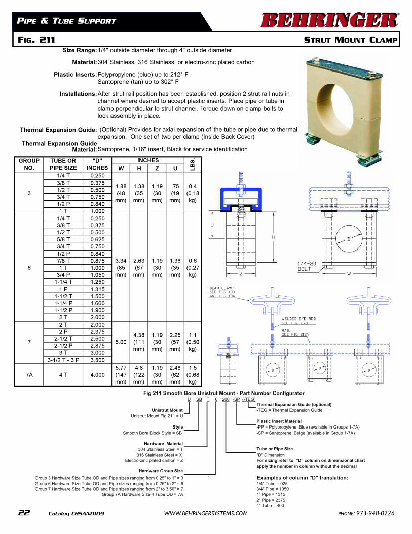
1/4" outside diameter through 4" outside diameter.
304 Stainless, 316 Stainless, or electro-zinc plated carbon
Polypropylene (blue) up to 212° FSantoprene (tan) up to 302° F
After strut rail position has been established, position 2 strut rail nuts inchannel where desired to accept plastic inserts. Place pipe or tube inclamp perpendicular to strut channel. Torque down on clamp bolts tolock assembly in place.
-(Optional) Provides for axial expansion of the tube or pipe due to thermalexpansion. One set of two per clamp (Inside Back Cover)
Santoprene, 1/16" insert, Black for service identification
Thermal Expansion Guide (optional)Unistrut Mount -TEG = Thermal Expansion Guide
Unistrut Mount Fig 211 = UPlastic Insert Material
Style -PP = Polypropylene, Blue (available in Groups 1-7A) Smooth Bore Block Style = SB -SP = Santoprene, Beige (available in Group 1-7A)
Hardware Material304 Stainless Steel = T Tube or Pipe Size
316 Stainless Steel = X "D" DimensionElectro-zinc plated carbon = Z For sizing refer to "D" column on dimensional chart
apply the number in column without the decimalHardware Group Size
Group 3 Hardware Size Tube OD and Pipe sizes ranging from 0.25" to 1" = 3 ` Examples of column "D" translation:Group 6 Hardware Size Tube OD and Pipe sizes ranging from 0.25" to 2" = 6 1/4" Tube = 025Group 7 Hardware Size Tube OD and Pipe sizes ranging from 2" to 3.50" = 7 3/4" Pipe = 1050
Group 7A Hardware Size 4 Tube OD = 7A 1" Pipe = 13152" Pipe = 23754" Tube = 400
Fig 211 Smooth Bore Unistrut Mount - Part Number Configurator-SP (-TEG)U SB T 2006
FIG. 211 STRUT MOUNT CLAMP
W H Z U1/4 T 0.2503/8 T 0.3751/2 T 0.5003/4 T 0.7501/2 P 0.8401 T 1.000
1/4 T 0.2503/8 T 0.3751/2 T 0.5005/8 T 0.6253/4 T 0.7501/2 P 0.8407/8 T 0.8751 T 1.000
3/4 P 1.0501-1/4 T 1.250
1 P 1.3151-1/2 T 1.5001-1/4 P 1.6601-1/2 P 1.900
2 T 2.0002 T 2.0002 P 2.375
2-1/2 T 2.5002-1/2 P 2.875
3 T 3.0003-1/2 T - 3 P 3.500
1.5 (0.68 kg)
LB
S.
0.4 (0.18 kg)
0.6 (0.27 kg)
1.1 (0.50 kg)
INCHES
1.88 (48
mm)
3.34 (85
mm)
5.004.38 (111 mm)
TUBE OR PIPE SIZE
"D" INCHES
GROUP NO.
3
6
71.19 (30
mm)
2.25 (57
mm)
1.38 (35
mm)
1.19 (30
mm)
.75 (19
mm)
2.63 (67
mm)
1.19 (30
mm)
1.38 (35
mm)
2.48 (62
mm)7A
5.77 (147 mm)
4.8 (122 mm)
1.19 (30
mm)4 T 4.000
PIPE & TUBE SUPPORT
Size Range:
Hardware Material:
Plastic Inserts:
Installations:
Thermal Expansion Guide:
Thermal Expansion Guide Material:
1/4” outside diameter through 6.625” outside diameter
304 Stainless, 316 Stainless, or electro-zinc plated carbon
Polypropylene (blue) up to 212° FSantoprene (beige) up to 302° FHDPE (white) up to 180° FVekton (black) up to 350° F
Cut bar in field to proper length. Field weld hang or floor mount bar tosupport structure. Fig 221 can also be used in combination with the figure225 or 226 stanchions. This combination will allow the support to beadjusted telescopically to the tube or pipe elevation. Call customer service for the price and availability of special rod lengths.
-(Optional) Provides for axial expansion of the tube or pipe due to thermalexpansion. One set of two per clamp. (Inside Back Cover)
Santoprene, 1/16" insert, Black for service identification
Thermal Expansion Guide (optional)Rod Mount TEG = Thermal Expansion Guide
Rod Mount Assembly Fig. 221 = RRod Length
Style 6" = 0621="21BS=elytSkcolBeroBhtoomS
18" = 18Harware Material 24" = 24
elbaliavaerashtgneLlaicepST=leetSsselniatS403316 Stainless Steel = X
Electro-zinc plated carbon = Z Plastic Insert MaterialPP- = Polypropylene, Blue (available in Groups 1-7A)
Hardware Group Size SP- = Santoprene, Beige (available in Group 1-8))9&8spuorGnielbaliava(etihW,EPDH=-NN3="1ot"52.0morfgnignarsezisepiPdnaDOebuTeziSerawdraH3puorG)9&8spuorGnielbaliava(kcalB,notkeV=-TH6="2ot"52.0morfgnignarsezisepiPdnaDOebuTeziSerawdraH6puorG
Group 7 Hardware Size Tube OD and Pipe sizes ranging from 2" to 3.50" = 7Group 7A Hardware Size Tube OD and Pipe sizes ranging from " to 4.5" = 7A Tube or Pipe Size
noisnemiD"D"8="526.6ot"6morfgnignarsezisepiPdnaDOebuTeziSerawdraH8puorGFor sizing refer to "D" column on dimensional chartapply the number in column without the decimal
Fig 221 Smooth Bore Rod Mount - Part Number Configurator(-TEG)-PP -06R SB Z 10506
1/4 T 0.2503/8 T 0.3751/2 T 0.5003/4 T 0.7501/2 P 0.8401 T 1.000
1/4 T 0.2503/8 T 0.3751/2 T 0.5005/8 T 0.6253/4 T 0.7501/2 P 0.8407/8 T 0.8751 T 1.000
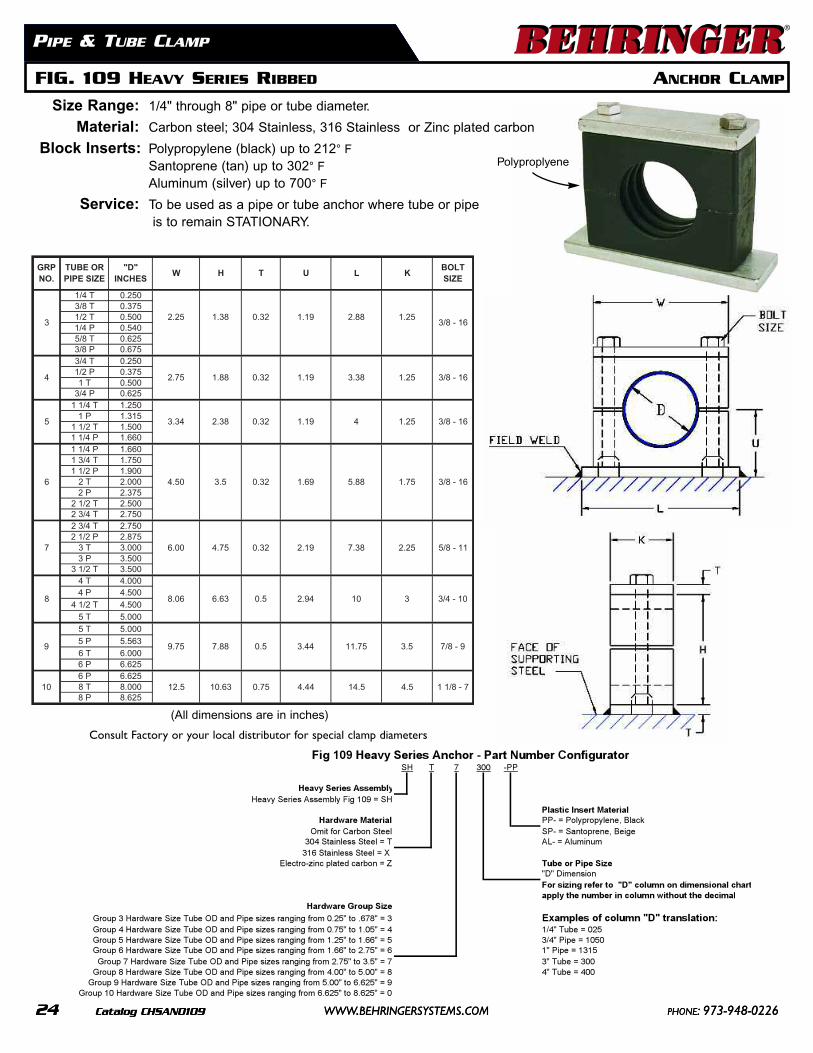
Consult Factory or your local distributor for special clamp diameters
Polyproplyene
FIG. 109 HEAVY SERIES RIBBED ANCHOR CLAMP
PIPE & TUBE CLAMP
1/4 T 0.2503/8 T 0.3751/2 T 0.5001/4 P 0.5405/8 T 0.6253/8 P 0.6753/4 T 0.2501/2 P 0.3751 T 0.500
3/4 P 0.6251 1/4 T 1.250
1 P 1.3151 1/2 T 1.5001 1/4 P 1.6601 1/4 P 1.6601 3/4 T 1.7501 1/2 P 1.900
2 T 2.0002 P 2.375
2 1/2 T 2.5002 3/4 T 2.7502 3/4 T 2.7502 1/2 P 2.875
3 T 3.0003 P 3.500
3 1/2 T 3.5004 T 4.0004 P 4.500
4 1/2 T 4.500
5 T 5.000
5 T 5.000
5 P 5.563
6 T 6.0006 P 6.6256 P 6.6258 T 8.0008 P 8.625
3
3.5
4.5
1.25
1.25
1.25
1.75
2.25
5.88
7.38
10
11.75
14.5
3/4 - 10
9.75
L K
2.88
3.38
4
9
10
8.06 6.63 0.5 2.94
7
8
6.00 4.75 0.32 2.19
61 - 8/391.123.083.243.35
7/8 - 9
0.32
0.32
23.088.157.24
6
3
3/8 - 16
5/8 - 11
7 - 8/1 144.457.036.015.21
7.88 0.5 3.44
GRPNO.
W H T
4.50
2.25 1.38
3.5
3/8 - 16
UBOLTSIZE
3/8 - 16
TUBE OR PIPE SIZE
"D"INCHES
1.69
1.19
1.19
Heavy Series AssemblyHeavy Series Assembly Fig 109 = SH
Plastic Insert MaterialHardware Material PP- = Polypropylene, Black
egieB,enerpotnaS=-PSleetSnobraCroftimO304 Stainless Steel = T AL- = Aluminum
316 Stainless Steel = X Electro-zinc plated carbon = Z Tube or Pipe Size
"D" DimensionFor sizing refer to "D" column on dimensional chartapply the number in column without the decimal
Hardware Group Size
Group 3 Hardware Size Tube OD and Pipe sizes ranging from 0.25" to .678" = 3 Examples of column "D" translation:520=ebuT"4/14="50.1ot"57.0morfgnignarsezisepiPdnaDOebuTeziSerawdraH4puorG0501=epiP"4/35="66.1ot"52.1morfgnignarsezisepiPdnaDOebuTeziSerawdraH5puorG
Group 9 Hardware Size Tube OD and Pipe sizes ranging from 5.00" to 6.625" = 9Group 10 Hardware Size Tube OD and Pipe sizes ranging from 6.625" to 8.625" = 0
SH T 7 -PP300Fig 109 Heavy Series Anchor - Part Number Configurator
(All dimensions are in inches)
Size Range: 1/4" through 8" pipe or tube diameter.
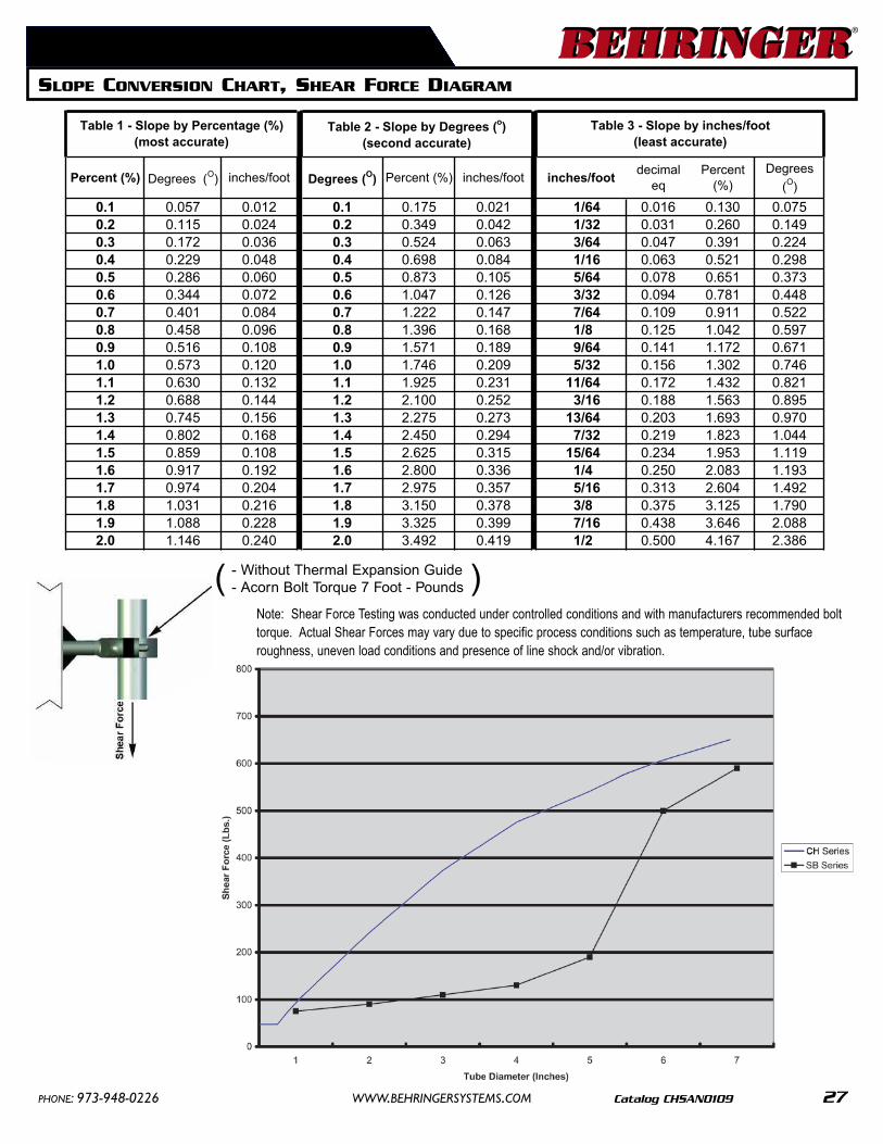
Note: Shear Force Testing was conducted under controlled conditions and with manufacturers recommended bolttorque. Actual Shear Forces may vary due to specific process conditions such as temperature, tube surfaceroughness, uneven load conditions and presence of line shock and/or vibration.