HAL Id: hal-01313827 https://hal.archives-ouvertes.fr/hal-01313827 Submitted on 12 May 2016 HAL is a multi-disciplinary open access archive for the deposit and dissemination of sci- entific research documents, whether they are pub- lished or not. The documents may come from teaching and research institutions in France or abroad, or from public or private research centers. L’archive ouverte pluridisciplinaire HAL, est destinée au dépôt et à la diffusion de documents scientifiques de niveau recherche, publiés ou non, émanant des établissements d’enseignement et de recherche français ou étrangers, des laboratoires publics ou privés. The bias-extension test for the analysis of in-plane shear properties of textile composite reinforcements and prepregs: a review P. Boisse, N. Hamila, E. Guzman-Maldonado, Angela Madeo, G. Hivet, F. Dell’Isola To cite this version: P. Boisse, N. Hamila, E. Guzman-Maldonado, Angela Madeo, G. Hivet, et al.. The bias-extension test for the analysis of in-plane shear properties of textile composite reinforcements and prepregs: a review. International Journal of Material Forming, Springer Verlag, 2017, 10 (4), pp.473-492. 10.1007/s12289- 016-1294-7. hal-01313827
Transcript
HAL Id: hal-01313827https://hal.archives-ouvertes.fr/hal-01313827
Submitted on 12 May 2016
HAL is a multi-disciplinary open accessarchive for the deposit and dissemination of sci-entific research documents, whether they are pub-lished or not. The documents may come fromteaching and research institutions in France orabroad, or from public or private research centers.
L’archive ouverte pluridisciplinaire HAL, estdestinée au dépôt et à la diffusion de documentsscientifiques de niveau recherche, publiés ou non,émanant des établissements d’enseignement et derecherche français ou étrangers, des laboratoirespublics ou privés.
The bias-extension test for the analysis of in-plane shearproperties of textile composite reinforcements and
prepregs: a reviewP. Boisse, N. Hamila, E. Guzman-Maldonado, Angela Madeo, G. Hivet, F.
Dell’Isola
To cite this version:P. Boisse, N. Hamila, E. Guzman-Maldonado, Angela Madeo, G. Hivet, et al.. The bias-extension testfor the analysis of in-plane shear properties of textile composite reinforcements and prepregs: a review.International Journal of Material Forming, Springer Verlag, 2017, 10 (4), pp.473-492. �10.1007/s12289-016-1294-7�. �hal-01313827�
The bias-extension test for the analysis of in-plane shear properties of textile composite reinforcements and prepregs: a review
P. Boisse1 & N. Hamila1
& E. Guzman-Maldonado1 & A. Madeo2
& G. Hivet3 & F. dell’Isola4
Abstract The bias-extension test is a rather simple ex-periment aiming to determine in-plane shear propertiesof textile composite reinforcements. However the me-chanics during the test involves fibrous material at largeshear strains and large rotations of the fibres. Severalaspects are still being studied and are not yet modeledin a consensual manner. The standard analysis of thetest is based on two assumptions: inextensibility of thefibers and rotations at the yarn crossovers without slip-page. They lead to the development of zones with con-stant fibre orientations proper to the bias-extension test.Beyond the analysis of the test within these basic as-sumptions, the paper presents studies that have beencarried out on the lack of verification of these hypoth-esis (slippage, tension in the yarns, effects of fibrebending). The effects of temperature, mesoscopic model-ing and tension locking are also considered in the caseof the bias-extension test.
Textile composite reinforcements are usually made of yarnsthemselves composed of thousands of fibers, the diameter ofwhich is very small (7 μm for a carbon fibre). The link of twoinitially orthogonal sets of yarns (warp and weft) allows toobtain a textile that can be seen as a quasi-continuousmaterial.Warp and weft yarns can be woven following a 2D pattern(plain weave, twill or satin). In NCF (Non Crimp Fabrics) twolayers (or more) of parallel yarns are linked by stitches in orderto both insure coherence of the reinforcement and avoid crimpof the yarns. The interlock and 3D weavings link serval warpand weft yarn layers to obtain a large thickness. When thereinforcements are made of two yarn directions and whenthese yarns are linked by weaving or stitching, they can beshaped on a double curve surface. The fibres used in compos-ites are quasi inextensible, consequently this shaping is ob-tained by in-plane shear of the textile reinforcement. For in-stance Fig. 1 shows the in-plane shear in the case of a hemi-spherical forming. Shaping (or draping) of prepregs is broadlysimilar. The resin present in the preimpregneted reinforce-ments is soft enough to render the forming by in-plane shearpossible. In thermoset prepregs the resin is soft because it isnot yet polymerized. Thermoplastic prepregs are heated overmatrix melting temperature before forming. In all these casesin-plane shear of the textile reinforcement is the main defor-mation mode to obtain double curved shapes. For a givenreinforcement they is a limit to shear angle. Over this value,wrinkling will appear (Fig. 2) [2–5]. This limit, often called‘locking angle’, depends on textile reinforcement propertiesalthough there is no direct relation between shear angle andwrinkling. Wrinkling is a global phenomenon depending onall strains and stiffnesses and on boundary conditions [5].
Because in-plane shear is the main deformation mode oftextile reinforcement during forming, it is the most studied
property of textile composite reinforcement. It is an importantdata for draping simulations [6–10]. In LCM processes, theshear angle in the preform after draping modifies the perme-ability [11–14].
Studies on experimental fabric in-plane shear behaviorstarted in the sixty’s in particular with the works of Lindberg[15] and Grosberg [16, 17]. The physical phenomena duringin-plane shear, such as contact and friction between the yarnsare related to shearing properties. Spivak introduced in 1968the ‘test of bias-extension’ as a relatively simple test that canbe compared to ‘rather sophisticated instrumental or experi-mental methods’ that have been previously used to analyze in-plane shear properties [18]. Nevertheless the geometry and theresulting kinematics of the test are not yet specified. Skeltondetermines the limit shear angle from the geometry of thefabric and of the yarns [19]. McGuinness and O. Bradaighexperimentally analyses the shearing of fabric reinforced ther-moplastic sheets using a picture frame test [20]. This pictureframe test is one of the two main experiments used to measuretextile reinforcement properties. The bias-extension test is thesecond one. The description of the bias-extension test with itspecificities, the geometry of the specimen and the differentshear zone was made byWang et al. in 1998 [21]. The authorscompleted this work especially in term of prediction of the
shear force and analysis of yarn slippage [22, 23]. The bias-extension test is used to measure the in-plane shear character-istic of cross-plied unidirectional prepregs in [24].
The bias-extension test highlights several specific aspectsdue to the fibrous constitution of the specimen associated tolarge strains. The works on this shear test are numerous andsome of them are recent. The objective of this paper is to makea survey of the works concerning the bias-extension test fortextile composite reinforcements. First, based on basic as-sumptions, equations are given i.e. the relation between thein-plane shear angle and the specimen extension and the rela-tion between the in-plane shear stress and the load on thetensile machine. This is not a simple point because the ‘shearstress’ is not defined in a consensual manner. Extension of thebias-extension test to high temperature tests that are necessaryto analyze thermoplastic prepreg will be presented. Then, be-cause the bias-extension test is based on strong assumptions,many studies concern their lack of verification. In particular,the influence of tension and of slippage in the specimen havebeen studied. The numerical simulation of the bias-extensiontest highlight difficulties especially, tension locking. The basicassumption assume constant in-plane shear zones and conse-quently a sharp transition of the fibre orientation at the changeof zone. Actually transition areas exist between the zones thatare due to fibre bending stiffness. These transition areas in thetextile reinforcement can be modelled using macroscopic con-tinuum models by introducing energies depending on secondgradient of displacement. Finally the slippage in the bias-extension test will be analyzed by mesoscopic F.E. analysesi.e. modeling each yarn in contact and friction with itsneighbors.
The two experimental tests to analyze in-plane shearproperties of composite reinforcements
The picture-frame (trellis-frame) test (Fig. 3) and the bias-extension test (Fig. 4) are the two experimental tests mainlyused for in-plane shear characterization of composite rein-forcements and prepregs [25]. Some other tests have beenproposed in which a rectangular fabric specimen is clampedon two opposite edges that prescribe an in-plane shear defor-mation to the specimen [15, 17, 26]. In these tests the speci-men is generally subjected to shear and tensions. To avoidtensions, rigid bar can be added to the two free edges. In thiscase the test is close to picture frame. A shear test by means oftorsion have been recently proposed for the analysis of UDprepregs (limited to small shear strains). Their mechanicalbehavior are specific because of the lack of cohesion in thedirection normal to the fibres [27].
A picture frame, shown in Fig. 3 is a hinged frame withfour rigid bars with equal length. A tensile force is appliedacross diagonally opposing corners of the picture frame rig
Shear angle =45°
Fig. 1 Forming a woven reinforcement on a double curve shape requiresin-plane shear deformations
Wrinkles
Shear angle > 50°
Fig. 2 Wrinkling induced by large shear angles [1]
Int J Mater Form
causing the picture frame to move from an initially squaregeometry into a lozenge. The specimen within the pictureframe is theoretically subjected to a pure and constant in-plane shear strain [2, 20, 25, 28, 29].
The bias-extension test consists in a tensile test on a rect-angular textile reinforcement such that the warp and weft towdirections are orientated initially at 45° to the direction of the
applied tension (Fig. 4). The initial length of the specimenmust be more than twice the width of the specimen in a biastest. Under this condition, yarns in the central zone C are freeat their both ends. If there is no slip between warp and weftyarn and assuming yarns being inextensible, the deformationin zone C is trellising and zone C is in pure shear. The shearangle in zones B is half those of zone C. One end of both warpand weft yarns of zone A is fixed in the clamp, consequently,assuming yarns being inextensible and no slip occurs, zone Aremains undeformed. Finally, assuming the yarns do not ex-tend, that there is no slip and neglecting the bending stiffnessof the yarns, the bias-extension test leads to zones with con-stant in-plane shear (C), half in-plane shear (B) and unde-formed (A). It is assumed that the in-plane shear is constantin each zone and this is first verified experimentally on bias-extension tests. Nevertheless it will be shown below that thisassumption can be discussed.
The deformed shape with three zones, A,B,C is less simplethat those of the picture frame where all the specimen is as-sumed to be subjected to a constant in-plane shear.Nevertheless a strong advantage of the bias-extension test liesin the fact that the yarns of the sheared zones are free at theiredge (at least one) and consequently there is no tension in theyarns (or only small tensions due to the warp-weft interac-tions). In the picture frame all the yarns are clamped in theframe and any misalignment of the specimen will lead to an
Fig. 3 Picture frame equipped with an optical system
f20f10
e20
e10
45°
Fig. 4 Bias-extension test
Int J Mater Form
increase of the measured load. Several comparison studieshave be performed [30–33]. Figure 5 shows the shear forceobtained with both experiments on a carbon woven fabric[33]. The picture frame result is much larger than the shearforce measured by the picture frame. The picture frame usedin this study allows to measure the tensions in the yarns and toadjust it to a given value. When this tension is set to zero, theresult given by the picture frame is close to those of the bias-extension test. Measuring the in-plane shear in a textile mate-rial is difficult because the in-plane shear stiffness is small incomparison to tensile stiffness. Consequently any spurioustension during a test strongly perturbs the in-plane shear anal-ysis. One main advantage of the bias-extension test lies in theabsence of spurious tensions in the yarns of the sheared zones.Another advantage is its relative simplicity and its moderatedsize. This is important when the test is performed at hightemperature in an oven. An in-plane shear benchmark hasbeen realized by an international group of academic and in-dustrial researchers on different composite reinforcementsusing both picture frame and bias-extension tests [25]. Thisbenchmark has proved valuable for the community of com-posite materials because the materials and the tests are verydifferent regarding continuous materials such as polymers ormetals. It has been shown that the determination of the shearangle from the crosshead displacement is correct until 30–35°.Beyond this value, the direct measurement of the shear angleby optical methods is necessary. Finally the benchmark hasshown that standardization methods are useful to obtain shearproperties that can be used in numerical simulations.
Kinematics of the bias-extension test
Two relations are necessary to analyze the results of an in-plane shear test. A kinematic relation that relates the in-planeshear angle to the extension of the specimen and a relationbetween the shear stress in the fabric and the measured force
on the tensile machine. To establish these relations, the fol-lowing assumptions are made:
– yarns are inextensible (more precisely, their elongation isnull in the bias-extension test),
– there is no slippage between warp and weft yarns at thecross over points,
– bending stiffness of yarn is neglected.
These three first assumptions correspond to those of the“kinematical models” or ‘fishnet algorithm’ used for fabricdraping simulations based on geometry [34–36].Consequently, the shear angles in the three zone A,B,C areconstant in each zone.
The two relations of the bias-extension tests (kinematicrelation and shear load versus force on the tensile machine)have been established gradually [25, 31, 33]. The first one isthe relation between the shear angle γ in the central zone Cand the length of the stretched specimen (given by the dis-placement of the tensile machine d) (Fig. 4):
γ ¼ π2−2Arccos
Dþ dffiffiffi2
pD
� �ð1Þ
D=L− ℓ (Fig. 4) is the length of the central zone C. Theshear angle γ can also be measured directly by an opticalmeasure. Figure 6 shows the shear angle field obtained usinga DIC measure (digital image correlation) [25, 37, 38]. Thisoptical method is well suited for measurements of textile ma-terials for which sensors in contact with the fabric are difficultto use. Optical analyses of the strain field at mesoscopic scalei.e. within the yarn have been done for in-plane shear test(Fig. 7) [37, 39]. The displacement field within the yarn isobtained by a DIC analysis at different stages of the shear test.For small angles the relative displacement field inside a yarn isa rotation field. Strains in the yarn are negligible. The shearload is mainly due to friction between the warp and weft
Fig. 5 Comparison of the shear force measured by a picture-frame and abias-extension test [33]
Fig 6 Shear angle in a plain weave fabric bias-extension test obtainedfrom DIC [25]. (The angles given on the scales are 90°- γ)
Int J Mater Form
yarns. Then the geometry of the woven cell leads to yarnslateral contacts. The yarn is transversely compacted and thiscompaction is more important as the shear increases. It canlead to off-plane wrinkling.
Determination of shear forces
The shear angle is well accepted as the significant kinematicquantity in an in-plane shear test. The change of angle be-tween warp and weft directions is simple and meaningful.There is no such simple and consensual quantity to character-ize the efforts in the material during an in-plane shear test. In abias-extension test the load on the tensile machine is mea-sured. But it is a global quantity on the specimen. In order tocompare the in-plane shear property obtained with differentspecimens or different devices and especially to use the in-plane shear properties in a model, this global load is not suf-ficient. It is necessary at least to transform this global load to aquantity that account for the geometry of the specimen. Thevocabulary used in many articles by authors to achieve this, is‘normalisation’. That means obtain, from the load on the spec-imen, a load quantity independent of the geometry of the testand consequently that can be compared to other tests. Manypapers have been written on this subject even recently [25, 32,40–42]. The question is not simple. In a tensile test, the tensilestress can be obtained simply from the tensile load and thesection of the specimen. For a shear test at small strains theshear stress can be calculated in the initial orthogonalCartesian frame. It is not the case for in-plane shear test ontextile reinforcement for which the shear angles are large. Thedirections of the warp and weft yarns rotate much and theymust be followed to express the shear loads or shear stresses.In addition, if the comparison of two different tests is a justi-fied goal, to model forming processes, it could also be inter-esting to have a ‘load’ quantity that is conjugated to the shearangle to obtain a power or a strain energy.
Shear load calculation
The shear load Fsh has been introduced in [25, 32, 33, 40, 43].It is defined as the tangential load along the side of a fabricrhomboid element with unit dimensions (Fig. 8). These shearload create on the fabric element a torque (or moment) Ms :
Ms γð Þ ¼ Fsh cosγ ð2Þ
γ=π/2-α is the shear angle.α is the angle between the twowarp and weft directions (Fig. 8).
It is possible to relate the shear load Fsh to the load on themachine F of the bias-extension test. Denoting SB and SC theinitial areas of zone B and C [25, 33]:
F d•¼ Ms γð Þ SC γ
• þMsγ2
� �SB
γ•
2ð3Þ
Fig. 7 Displacement field withina yarn at different stage ofshearing
FshFsh
Fig. 8 Normalized load and shear load on a rhomboid with unit side
Int J Mater Form
Ms γð Þ SC γ• is the power of shear in the central part C of
the specimen andMsγ2
� �SB
γ•
2 is the power of shear in the zonesB.
From the geometry of the specimen this leads to:
Ms γð Þ ¼ F D
ℓ 2D−ℓð Þ cosγ2− sin
γ2
� �−
ℓ2D−ℓ
Msγ2
� �ð4Þ
Using equation 2,
Fsh γð Þ ¼ F D
ℓ 2D−ℓð Þcosγ cosγ2− sin
γ2
� �−
ℓcosγ=22D−ℓð Þcosγ Fsh
γ2
� �ð5Þ
Equation 5 gives Fsh(γ) incrementally.
Shear moment calculation
The shear load, as defined above, permits to compare the bias-extension tests performed by different groups using differentspecimen geometries. It also permits to compare these resultswith picture frame tests [25]. Nevertheless it is not a quantitythat is conjugated to the shear angle γ.
On the other hand, it is the case of the moment per surfaceMs defined in equation 2. The loads on a woven unit cell(Fig. 9a) lead to the resultant tensions T1, T2, to the resultantbending moment M1, M2 and to the in-plane shear momentMs. In a virtual displacement field η, the virtual in-plane shearwork is
Ws ηð Þ ¼ γ ηð ÞMs ð6Þ
The shear moment Ms is a stress resultant. It is a resultgiven by a bias extension on the specimen since it is relatedto the global load by equation (4). This in-plane shear virtualwork (equation (6)) can be used in particular for the formula-tion of finite elements made of textile material [7, 39, 44, 45].It can be notice that equation (5) that relates the shear load tothe load on the machine, has been established using the shearmoment Ms because it appears in the power balance(Equation 3).
Static approach
The relation between the shear moment and the load onthe machine (4) can also be obtained from a static equi-librium. In Fig. 10, the case L= 2ℓ is considered. Thebias-extension test can be modeled as a hinged frame,the bars of which are submitted to a shear momentM12 =M1+ M2. The shearing of the central zone C ofthe specimen leads to a moment M1 and the shearing ofthe zone B lead to a moment M2. Denoting Lb thelength of the bar AB, the equilibrium of ABD leadsto Ax = 0 (Fig. 10). The equilibrium of AB leads to:
Bx ¼ 0 and By ¼ M12=Lbsinα=2� � ð7Þ
Taking into account that ℓ ¼ ffiffiffi2
pLb and α
2 ¼ π4 −
γ2, the
load F on the machine is,
F ¼ ℓ
cosγ2− sin
γ2
Ms γð Þ þMsγ2
� �� �ð8Þ
This is consistent with equation (4) when L=2ℓ.
Cauchy stress components
In the bias-extension test the textile specimen is consid-ered as a continuum. Consequently the internal loadswithin the material can then be represented by a stresstensor. The components of this tensor, especially theshear stress components can be an alternative to theshear load and shear moment to quantify the internalshear efforts in the materials. The mechanical behaviorof a woven textile material is strongly dependent ondirections of directions of the warp and weft yarns.Consequently the basis defined by these yarn directionsare preferred to express the stress tensor componentsand the mechanical behavior of the textile material.These fibre directions do not remain perpendicular during the
Fig. 9 (a) Loads on a unit woven cell and resultants: (b) tensions, (c) in-plane shear moment, (d) bending moments
Int J Mater Form
reinforcement deformation especially in the bias-extension test.Consequently, there are different variances for the stress com-ponents in the frame defined by warp and weft yarns. Therelationships between these components and the exterior ap-plied loads can be determined but are not straightforward [46].
The curvilinear material coordinates ξ1 and ξ2 (Fig. 11)along warp and weft yarns define the material covariant basevectors at point M:
g1¼ ∂OM
∂ξ1and g
2¼ ∂OM
∂ξ2ð9Þ
The associated contravariant base vectors gα are such as :
gα⋅g
β¼ δα
β ð10Þ
Where α, β, are indices taking the values 1 or 2 and δαβ is the
Kronecker symbol. The covariant, contravariant and mixedcomponents of the Cauchy stress tensor in the frames defined
by the material covariant base vectors gαand contravariant
base vectors gα are considered [47]:
σ ¼ σαβ gα⊗g
β¼ σαβ g
α⊗g
β¼ σα
β gα⊗g
β
¼ σαβ g
α⊗g
βð11Þ
⊗ denotes the tensorial product [47]. Denoting nα and nα
the unit normal vectors in gαand gα directions, and dSnα , d
Snα the corresponding elementary surface, the elementaryforce vector dFnα on dSnα has two components, the first
one, denoted dTnα , on the normal nα in the material directionα, the second one, denoted dRnα , in the perpendicular direc-tion n3−α (Fig. 11) [46]:
dFnα ¼ dTnαnα þ dRnαn3−α ¼ dTnα
gα
gα
þ dRnα
g3−α
g3−α
ð12Þ
As,
dFnα ¼ σ⋅nα� �
dSnα ð13Þ
The stress components in equation (11) can be related to dTnα and dRnα . These relations are given in [46]. In the case ofa pure shear loading (dT ¼ 0 ), two sets of components(σ ¼ σαβg
α⊗g
βand σ ¼ σα
βgα⊗gβ ) enable to obtain both
null direct stresses and a direct relationship between the trans-verse load components and the transverse stresses. Thus, theseframes and the corresponding stress components are thosesuited to analyze a pure transverse loading. For the othersthe pure shear will lead to direct stress components.
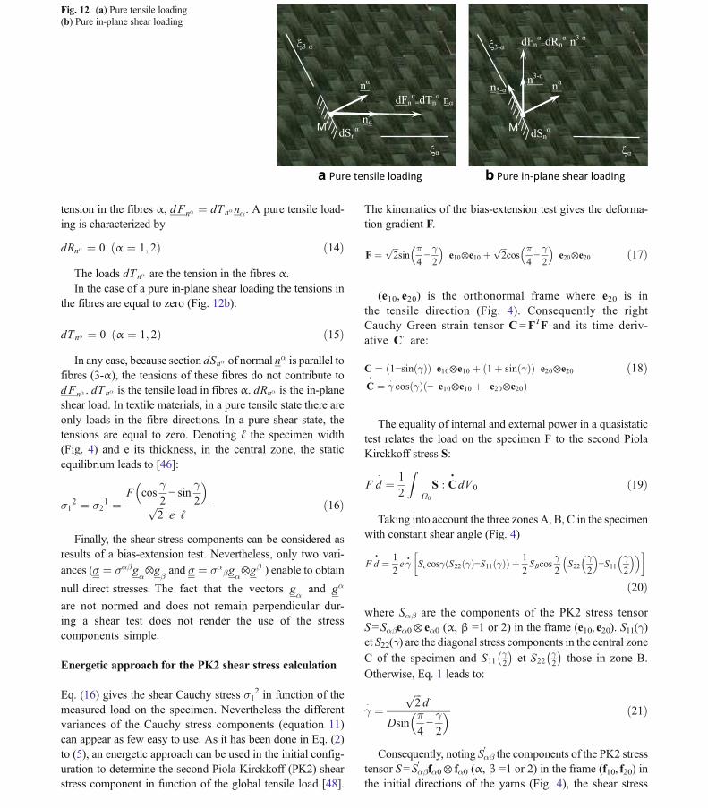
In a textile material with two fibre directions the elementarysection dSnα of normal nα is parallel to the fibres (3-α)(Fig. 12a). Consequently, these fibres do not exert any loadon this section. The load on the section dSnα is only due to the
Fig. 10 Static analysis of the bias-extension test
M
nn
dFn
dRn
dTn
dSn
Fig. 11 Material coordinates, normal, elementary surfaces and elementary loads
Int J Mater Form
tension in the fibres α, dFnα ¼ dTnαnα. A pure tensile load-ing is characterized by
dRnα ¼ 0 α ¼ 1; 2ð Þ ð14Þ
The loads dTnα are the tension in the fibres α.In the case of a pure in-plane shear loading the tensions in
the fibres are equal to zero (Fig. 12b):
dTnα ¼ 0 α ¼ 1; 2ð Þ ð15Þ
In any case, because section dSnα of normal nα is parallel tofibres (3-α), the tensions of these fibres do not contribute todFnα . dTnα is the tensile load in fibres α. dRnα is the in-planeshear load. In textile materials, in a pure tensile state there areonly loads in the fibre directions. In a pure shear state, thetensions are equal to zero. Denoting ℓ the specimen width(Fig. 4) and e its thickness, in the central zone, the staticequilibrium leads to [46]:
σ12 ¼ σ2
1 ¼F cos
γ2− sin
γ2
� �ffiffiffi2
pe ℓ
ð16Þ
Finally, the shear stress components can be considered asresults of a bias-extension test. Nevertheless, only two vari-
ances (σ ¼ σαβgα⊗g
βand σ ¼ σα
βgα⊗gβ ) enable to obtain
null direct stresses. The fact that the vectors gα
and gα
are not normed and does not remain perpendicular dur-ing a shear test does not render the use of the stresscomponents simple.
Energetic approach for the PK2 shear stress calculation
Eq. (16) gives the shear Cauchy stress σ12 in function of the
measured load on the specimen. Nevertheless the differentvariances of the Cauchy stress components (equation 11)can appear as few easy to use. As it has been done in Eq. (2)to (5), an energetic approach can be used in the initial config-uration to determine the second Piola-Kirckkoff (PK2) shearstress component in function of the global tensile load [48].
The kinematics of the bias-extension test gives the deforma-tion gradient F.
F ¼ffiffiffi2
psin
π4−γ2
� �e10⊗e10 þ
ffiffiffi2
pcos
π4−γ2
� �e20⊗e20 ð17Þ
(e10, e20) is the orthonormal frame where e20 is inthe tensile direction (Fig. 4). Consequently the rightCauchy Green strain tensor C =FTF and its time deriv-ative C� are:
C ¼ 1−sin γð Þð Þ e10⊗e10 þ 1þ sin γð Þð Þ e20⊗e20
C•¼ γ
�cos γð Þ − e10⊗e10 þ e20⊗e20ð Þ
ð18Þ
The equality of internal and external power in a quasistatictest relates the load on the specimen F to the second PiolaKirckkoff stress S:
F d�¼ 1
2
ZΩ0
S : C•dV 0 ð19Þ
Taking into account the three zones A, B, C in the specimenwith constant shear angle (Fig. 4)
F d•¼ 1
2e γ
•Sccosγ S22 γð Þ−S11 γð Þð Þ þ 1
2SBcos
γ2
S22γ2
� �−S11
γ2
� �� � �
ð20Þwhere Sαβ are the components of the PK2 stress tensorS=Sαβeα0⊗ eα0 (α, β =1 or 2) in the frame (e10, e20). S11(γ)et S22(γ) are the diagonal stress components in the central zoneC of the specimen and S11
γ2
� �et S22
γ2
� �those in zone B.
Otherwise, Eq. 1 leads to:
γ� ¼
ffiffiffi2
pd�
Dsinπ4−γ2
� � ð21Þ
Consequently, noting Sαβ′ the components of the PK2 stress
tensor S=Sαβ′ fα0⊗ fα0 (α, β =1 or 2) in the frame (f10, f20) in
the initial directions of the yarns (Fig. 4), the shear stress
a Pure tensile loading b Pure in-plane shear loading
Mn
n
dFn =dTn n
dSn
3-
M
n3-n
dFn =dRn n3-
dSn
3-
n3-
Fig. 12 (a) Pure tensile loading(b) Pure in-plane shear loading
Int J Mater Form
component S012 ¼ 1
2 S22−S11ð Þ can be calculated incrementallyfrom the load on the specimen F.
S012 γð Þ ¼
FD cosγ2
� �−sin
γ2
� �� �2SCecosγ
−SBcos
γ2
4SCcosγS
012
γ2
� �ð22Þ
The inverse approach
In order to overcome the calculation of the force quantitiesdefined in the previous sections, the inverse approach [49,50] can be a way to identify the parameters relatives to in-plane shear of the used constitutive law. Finite element anal-yses of the bias-extension test are performed within an opti-misation loop in order to determine the in-plane shear coeffi-cients of the constitutive law that give the nearest F.E. analysesof the bias extension test. This approach avoids the use of theexplicit relation between in-plane shear stresses and the loadon the machine. Nevertheless this approach is not withoutdrawback. In particular, the identified coefficients may dependon the initial values used for the simulation.
Bias-extension tests at high temperature
The in-plane shear tests are used to measure the shear proper-ties of both dry composite reinforcements (used as preforms inthe RTM process) and thermoset and thermoplastic prepregs.The in-plane behaviour of prepregs is significantly differentfrom that of dry textile reinforcements. Depending on the stateof the resin, the in-plane shear are substantially modified.Nevertheless the manufacturing process needs that in-planeshear stiffness is weak enough in order to achieve doublycurved shapes. In the case of thermoset prepregs, manufactur-ing and consequently the in-plane shear tests are performedbefore curing. In the case of thermoplastic prepreg,manufacturing and shear tests are performed at a temperatureslightly over melting point. The in-plane shear tests must beperformed at all the temperatures in the material processingrange. The temperature may vary during the process and it isimportant that the actual properties are taken into account in aprocess simulation. Low temperature in a zone of a part duringa thermoforming process can lead to a high shear stiffness andwrinkling [51]. The bias extension test can be used to testprepregs in the material processing range because the resinis weak enough in this case so that the fibres lead to thedeformed shape of Fig. 4. This shape is due to inextensibilityof the yarns and rotations at the yarn crossovers withoutslippage.
Some in-plane shear tests have been performed fairlysoon within an oven [20, 31, 32]. A study of the effectof temperature on, in-plane shear behaviour of carbon
satin/ Peek and carbon satin/ PPS prepregs using a bias-extension test has been made recently in [52]. The bias-extension test is compact and can be easily performedwithin an environmental chamber (Fig. 13). It neverthe-less presents several difficulties. First the clamp of thespecimen is difficult since its efficiency decrease whenthe matrix reach the melting point (Fig. 14a). The mostimportant point is the necessity to have a constant tem-perature field in the specimen. If it is not the case theshear stiffness is not constant and the deformation ofthe specimen is no more those of the bias-extensiontest. Some zone, especially near the clamps that coolthe specimen can remain undeformed (Fig. 14b). In ad-dition it is not possible to wait a long time for a ther-mal equilibrium because the matrix are usually oxidizedby high temperature and the test must be achieved in amatter of some minutes [53].
The bias-extension tests are carried out for tempera-tures on both sides of the manufacturing temperature.This temperature is slightly larger than melting temper-ature. The objective of these experiments is to accountfor the effect of the temperature on the prepreg proper-ties in a forming simulation. A thermal analysis givesthe temperature of the prepreg during the forming. Thisone may vary over the part. The resulting change ofshear stiffness can affect the thermoforming process[51]. The loads on the specimen measured for bias-extension tests at temperature around the melting point(343 °C) for a carbon satin / PEEK matrix prepreg areshown Fig. 15. The influence of the temperature isstrong. The in-plane shear stiffness is much larger at320 °C than at 360 °C. Nevertheless over 360°, theshear stiffness does not decrease anymore because it ismainly those of the textile reinforcement.
In the case of the thermoplastic prepreg, the temper-ature is a main issue and the bias-extension tests mustbe done in function of the temperature. For these pre-pregs, the influence of the strain-rate can be testedusing bias-extension test at different speeds. Figures 16[8] and 17 [51] show the influence of the strain rate onin-plane shear force for two close prepreg with bothPPS matrix. The influence of strain rate exists, but itis less important than the influence of temperature.Depending on the process it can be taken into accountin the constitutive model or neglected [54, 55].
Influence of the tensions; biaxial bias-extension test
When a textile reinforcement is submitted to tension, the in-plane shear stiffness is increased. The influence of tension onin-plane shear behaviour has been investigated in the pictureframe test [30, 33, 56] and by modelling approaches [57]. Inthe picture frame test it is possible (although technically
Int J Mater Form
difficult) to add devices that impose tension in the yarns inaddition to the in-plane shear prescribed by the picture frame.It has been shown that the influence of those tensions areimportant. In particular they strongly influence the onset ofwrinkling [5, 58]. This is also a main difficulty of thestandard picture frame test because it is difficult toavoid spurious tensions in the specimen that perturbthe in-plane shear measurement [33]. On the other hand,in the bias-extension test the yarns have one or two freeextremities. Consequently the tensions in the yarns aresmall and they don’t disrupt the in-plane shear measure-ment. It is a main advantage of this test. The bias-extension test have been modified to analyse theshear-tension coupling. The biaxial bias-extension testis shown in Fig. 18 [58–60]. The objective of this testis to characterize wrinkling onset and tension in-planeshear coupling for woven textile reinforcements.
Nevertheless the kinematics of the test is not simpleand the use of this test needs to be strengthened.
Slippage mechanism during the bias-extension test
A main advantage of the bias-extension test is that theextremities of the yarns are free and consequently thatthere is no (or small) tension in the yarns. On the otherhand the reinforcement is weakly held in position. Thekinematics of the test is based on weaving that ensuresthat the cross over points act as fixed pin-jointednodes. When the shear angles are large, slippage be-tween the warp and weft yarns occurs. It is a weaknessof the bias-extension test. This slippage has beenanalysed from the first studies on the bias-extensiontest [21, 22, 61]. Wang et al. observed that the slippage
Fig. 13 Bias-extension test on athermoplastic prepreg in anenvironmental chamber [51]
Cold zone under the mel�ng temperature
No deforma�on
Slippage in the jaws
Sliding of heels
Fig. 14 (a) Sliding of heels. (b)Inhomogeneity of temperatureand fusion (c) The bias extensiontest shape is not achieved becauseof slippage in the jaws
Int J Mater Form
occurs mainly near the frontiers of the zones with con-stant in-plane shear (Fig. 19). Actually the importanceof the slippage during a bias-extension test depends onthe cohesion provided by the weaving (or the stitchingfor NCF materials). Figure 20 shows the shear angleversus displacement for two composite reinforcements(a glass plain woven textile pattern [62] and a G1151interlock carbon fabric (manufactured by Hexcel) [63]).The theoretical angle (equation 1) obtained from thespecimen extension is compared to the angle measuredwith a camera. For shear angles inferior to 40°, theagreement between theoretical and measured shear an-gles is good. Over 40°, slippage between yarns occursand the measured angles are smaller than the theoreti-cal ones [62, 63]. Depending on the fabric and on thecohesion due to the weaving, the angle from which theslippage is significant (40° for the G1151) can differand can be smaller. Anyway, even if there if someslippage, the bias-extension test can be used to mea-sure the in-plane shear properties but the shear anglemust be measured independently of the grip displace-ment. This is in particular possible by using opticalstrain measurements.
Bias-extension test on NCF reinforcements
Among the textile composite reinforcements, the NCF(Non Crimp Fabrics) are made of continuous parallelfibres linked by stitching. They are made of one (UD-NCF), two (biaxial NCF) or three (triaxial NCF) direc-tion of fibres that are linked by stitching. The biaxialNCF are the more common (Fig. 21). They have twodirections of fibres (that are initially orthogonal) as wo-ven reinforcements. As stated in their name, the fibresare straight (non crimp) and they avoid the loss of stiff-ness and strength due to yarn crimp. In the other handthe stitching insures a cohesion to the reinforcement thatcan be formed on double curved shapes [6, 63–66]. Asthe bias-extension test of woven material is based onthe assumption that there is no slip between warp andweft yarns, one can ask whether the bias-extension testis possible for NCF. This depends on the stitching pat-tern. If the stitching insures a sufficient link betweenthe two fibre directions of the biaxial NCF and allowsthe rotation between warp and weft yarns, it plays therole of the weaving. In this case the bias-extension test
Fig. 15 Bias-extension test load in function of the temperature [52]
Fig. 16 Bias-extension tests at different rates on a PPS glass fabricprepreg [7]]
Fig. 17 Load versus displacement curves for carbon/PPS prepreg at300 °C for different displacement rates [51]
Fig. 18 The biaxial extension test (a) initial state (b) Deformed state [58]
Int J Mater Form
can be considered to measure the NCF in-plane shearproperties [63, 64, 66, 67]. The in-plane shear angle isdefined as the change in angle between the fibres of thetwo layers (initially orthogonal). It can be measuredusing two synchronised cameras, one on each side ofthe specimen [63]. For a given axial displacement ofthe grips of the tensile machine, the measured angleare smaller than the theoretical angle given by equation(1). For example, for the NCF shown in Fig. 21, thereis a difference about 30 % between the theoretical angle(equation (1)) and the angle measured with the twocameras (Fig. 22)[63]. The theoretical kinematic is normore valid, the non-slippage assumption between thetwo plies is not verified. An analysis of the deformation
of the bottom of the specimen shows some local slipthat are shown Fig. 23. Consequently it is not possibleto use the theoretical equations given in (1) to (5) andbased on the non-slippage assumption. It is necessary touse the shear angle measured by the two synchronisedcameras.
In [64] the bias-extension test of NCF is analysed by amesoscopic approach. The yarns are modelled by 3D finiteelements and the stitches by bar elements. This analysis allowsfrictional sliding between the yarns and the stiches. It leads toresults that are in good agreement with the experimental de-formation. However a mesoscopic analysis is not a simpleway to analyse a bias-extension test. The mesoscopic ap-proach of the bias-extension test will be detailed in a nextsection.
The slippage between the two plies of a biaxial NCFis often important in a forming process. The simulationof this process must take this slippage (some cm) intoaccount [63].
The UD-NCF are sewed unidirectional non crimpfabric. They are closer to UD reinforcements than towoven fabrics. There is a single direction of parallelcontinuous fibres in the material. Bias-extension testshave been performed on such UD-NCF [68]. The de-formed shape is far enough of the theoretical shape ofthe bias-extension test, but it is interesting to understandthe deformation modes of the material. Some specific
Fig. 19 Indication of slippage areas in a bias-extension test specimen[21]
Theore�cal angle
Mesured angle
Displacement (mm)
Fig. 20 Theoretical and measured shear angle during a bias-extensiontest (a) Glass plain woven textile pattern [62] (b) G1151 interlock carbonfabric [63]
Fig. 21 NCF warp yarns side, NCF weft yarns side
Fig. 22 Bias-extension test on a NCF. Comparison between theoreticaland experimental shear angle versus displacement of the grip. Angledeviation from theoretical angle (dashed line) [63]
Int J Mater Form
developments will be necessary to use this test to deter-mine the in-plane shear properties of UD-NCF.
Numerical difficulties in the simulationof the bias-extension test. tension locking
The simulation of the bias-extension test needs to beperform at finite strain with material non-linearities.The approach can be implicit or explicit [7, 8, 64,69]. A specific numerical problem which is a lockingphenomenon has been highlighted [70–72]. In the bias-extension test, fibre yarns are oriented at ±45° to thespecimen axis. Since the specimen is rectangular, thesimplest mesh is obtained by a regular division intosquare or rectangular four node elements as inFig. 24a. The result of the simulation is not correct.The obtained shape (Fig. 24b) is not those of the bias-extension test (Fig. 4). The computed load on the spec-imen is strongly overestimated (Fig. 24c). In the otherhand, a mesh oriented in the fibre direction gives acorrect result (Fig. 25). This problem is due to the verylarge tensile stiffness of the woven reinforcement in thewarp and weft yarn directions. This leads to quasiinextensibility conditions in warp and weft directionsat each Gauss point. As there are four gauss pointsper quadrangular element, the eight inextensibility con-ditions (two fibre directions at each Gauss point) cannotbe verified as there are only two displacement degreesof freedom in a four node element (on average). Thisleads to locking called the tension locking.When the yarns arealigned with the element sides, the inextensibility equations in
Fig. 23 Deformation of thebottom of the NCF specimen.Simplification of the deformation[63]
Fig. 24 (a) Initial mesh aligned with the specimen. The fibers areoriented at ± 45° (b) Deformed mesh for a 65 mm displacement (c)Load on the tensile machine obtained by simulation and by experimentsand fibre extensions [72]
Int J Mater Form
the different Gauss points are identical and there can beverified. There are many cases of locking in finite ele-ment analyses: locking of incompressible materials [73],of transverse shear locking of C0 plate or shell elementswhen the thickness small [74] among other locking phe-nomena [75]. Under-integration can be a solution tolocking in particular to tension locking. The number ofinextensibility constraints per quadrangle decrease totwo and solutions exist. Nevertheless spurious singularmodes can develop without deformation energy. Thestabilization of these hourglass modes is necessary. Aspecific stabilization method has been developed in[72]. It is based on a Γ-projection method. It only actson the non-constant part of the in-plane shear strains.This approach is numerically efficient. It is shown thatlocking is eliminated in the case of four node elements.Figure 26 shows that a rectangular mesh based on thespecimen sides gives a correct solution when the meth-od is used. Some multi-field finite elements have beenproposed in order to avoid tension locking in [71].
Fiber bending stiffness and second gradientcontinuum
The idealized kinematics of the bias-extension test has beenpresented in Fig. 4. It is made of 7 zones of 3 types (A,B,C)with constant in-plane shear in each of them. This correspondsto a pin-joint kinematics. It is assumed that a continuous fibrehas a constant orientation in each of these zones with a sharpchange between zones. On the other hand, it is shown Fig. 27that the change of direction is not instantaneous but that atransition area can be observed (Fig. 27b) (highlighted bymeans of two yellow lines). Such transition area is due tothe bending stiffness of the fibres that lead to a curvatureradius between the two zones with a different fibre direction(C and B on Fig. 27b). The kinematics based on the pin-jointassumption described at the beginning of the paper leads todifferent and constant directions of the fibres in zone A, B, C.The experimental observations, on the other hand, show thatthe bending stiffness of the fibres actually leads to transitionareas. These zones cannot be described by the pin-joint
Fig. 25 (a) Simulation with amesh aligned with the yarns (c)Load versus displacement curveobtained with an aligned meshand fibre extensions [72]
Fig. 26 (a) Simulation with amesh aligned with the specimenusing the stabilization approach(c) Load versus displacementcurve obtained with an alignedmesh and fibre extensions [72]
Int J Mater Form
kinematics nor by a classical continuum approach. In order todescribe these zones, a generalized continuum theory may beused. A second gradient hyperelastic orthotropic continuumtheory for fibrous materials has been developed in [76, 77].The strain energy density depends both of the Right Cauchy-Green deformation tensorC=FT F and of its gradient∇C (F isthe deformation gradient tensor).
W C;∇Cð Þ ¼ WI Cð Þ þWII ∇Cð Þ ð23Þ
WI is the first gradient strain energy, WII is the secondgradient strain energy. Definitions and identifications of thefirst gradient strain energies for different fibrous reinforce-ments can be found in [78, 79] and of the second gradientstrain energy in [76, 77, 80]. The simulation of the bias-extension test based on the strain energy with a second gradi-ent part (equation 22) shows the transition areas that have beenhighlighted at the frontiers of the zones A, B, C (Fig. 28).
More generally, the second gradient approach is a way to takeinto account the local bending stiffness of the fibres. Thiscannot be described by classical continuum mechanicalmodels. However the implementation of these models intonumerical codes shows some difficulties which are being re-cently studied by means of other methods [81, 82]. Anotherway to account for the local fibre bending stiffness is theintroduction of a rigidity related to the curvature in continuumfinite element [83]. A detailed generalised plate model includ-ing geodesic bending energy, i.e. energy related to secondgradient in-place displacement, has been recently developedin [84–86].
Bias extension test on an unbalanced wovenreinforcement
A significant part of the textile composite reinforcements areunbalanced. Warp yarns are much larger than weft yarns. Thestrong warp yarns withstand the loads in the composite part.The small weft ones ensure the cohesion of the reinforcement.The importance of the in-plane bending stiffness of the fibresthat have been highlighted in the previous section and hasbeen shown to be significant in the case of balanced fabricbecomes even more important for unbalanced reinforcements.In particular, it has been shown that the asymmetric S-shapeobtained when an unbalanced reinforcement (Fig. 29) subject-ed to a bias extension test (Fig. 30) is due to the very differentin-plane bending stiffness of the warp and weft yarns [87, 88].In order to account for most fundamental deformation mech-anisms occurring in unbalanced reinforcements, a second gra-dient, hyperelastic, initially orthotropic continuum model hasbeen introduced in [87, 88]. The deformed shape obtainedfrom this approach shows a good agreement with the experi-ment (Figs. 30 and 31). It can be seen that the S-shape is due to
C
B B
A
Fig. 27 Transition layer between the zones with constant shear in a bias-extension test
Fig. 28 Simulation of a bias-extension test base on a second gradienttheory. Transition layers for the shear angle. [76] Fig. 29 Unbalanced fabric
Int J Mater Form
very different curvatures of the warp and weft yarns in thedeformed configuration.
Mesoscopic analysis
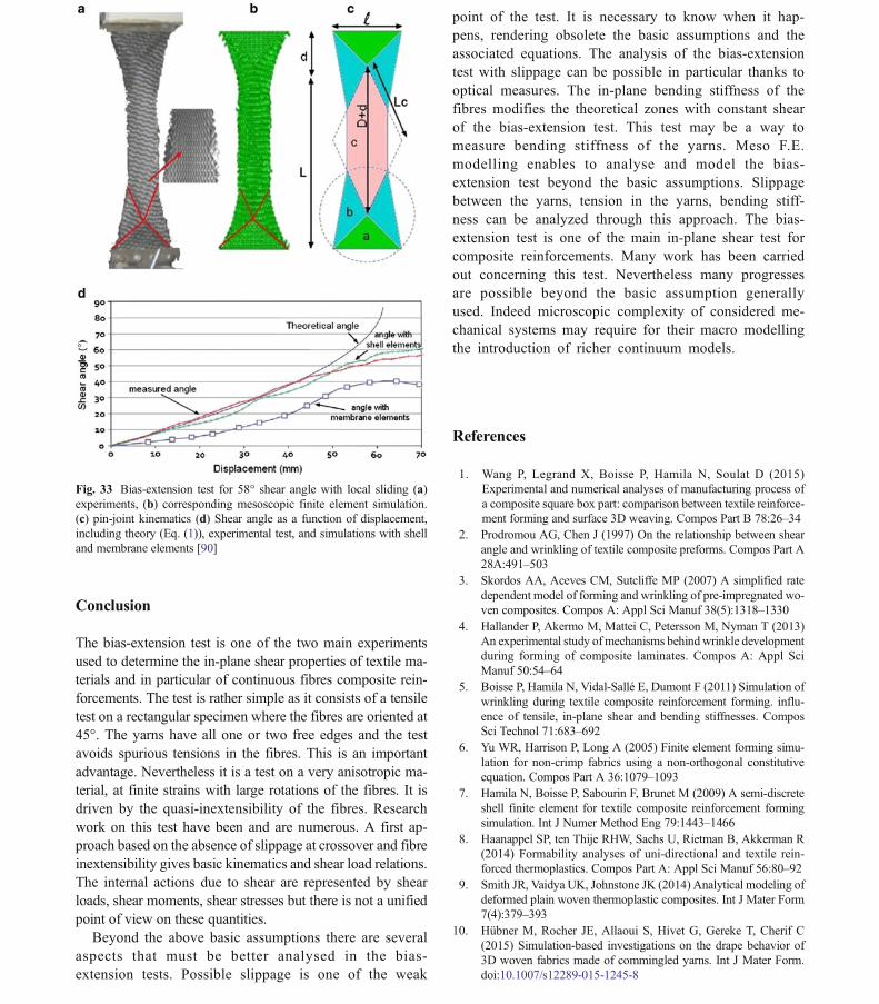
It has been seen above that slippage occurs in a bias-extensiontest especially for large shear angles. It can even happen forsmaller angles when the cohesion between warp and weftfibres is weak. This is the case for most NCF reinforcementsas shown above. In this case, the continuum mechanic ap-proaches are no more valid. In a mesoscopic approach eachyarn is considered as a solid in contact and possible slidingwith friction with its neighbours. The yarn is modelled as acontinuous material with a specific mechanical behaviour inorder to take into account that it is made of many (thousand)fibres. It is not a completely discrete modelling as the so calledmicroscopic approach where each fibre is modelled by a beamelement in contact-friction with the other fibres [89]. Themesoscopic approach allows to simulate the sliding betweenthe yarns (and the stitch in case of a NCF). Consequently thesimulation of the bias-extension test in case of slippage ispossible. The F.E. model used to described a woven cell mustbe simple enough to permit the computation of the wholereinforcement. Figure 32 shows a simplified unit woven cellwhere the yarns are described by shell finite elements [90].Contact with Coulomb friction between the elements is con-sidered. The mechanical constitutive model of the yarn musttake into account that it is made of thousands of fibres. Bothspecific hypoelastic [91–93] and hyperelastic [78, 94] lawshave been developed. The bending stiffness of the shell ele-ments is not related to the membrane stiffness because of thefibrous nature of the yarn. It is directly measured by a canti-lever bending test [95, 96]. Figure 33 compares the
experimental deformation of a bias-extension test on a glassplain weave specimen with the result of a mesoscopic simu-lation and with the theoretical shape based on the pin jointassumption. Up to 40° both theoretical and mesoscopicapproach give shear angles in correct agreement withthe experiments. Over 40° slippage occurs and the ex-perimental shear angle is smaller than the theoreticalone. The mesoscopic simulation using shell elements ison correct agreement and tracks the sliding of the yarnsover 40°. Membrane elements give poor results becausethe lack of bending stiffness leads to underestimatednormal contact loads and consequently underestimatedfriction loads and too large sliding.
A mesoscopic simulation of the bias-extension testfor NCF reinforcements is done in [64]. The yarns aremodel by solid elements and the stitches by bar ele-ments. Yarns and stitches are in contact with friction.The analysis of fibre slip in the specimen is analysed bythe mesoscopic model and compare to experiments.Other mesoscopic analysis are presented in [97]. Mesomodelling is an accurate approach to analyse the bias-extension test. These simulations allow to track the yarnslip. Nevertheless, the finite element models are com-plex with many contacts with friction. They must beused when the classical pin joint assumption for thebias extension test is not satisfactory.
Fig. 31 Simulation of the deformation using a second gradient approach[87]
Fig. 32 The mesoscopic model of unit cell of plain weave
Fig. 30 Experimental S-shape [87]
Int J Mater Form
Conclusion
The bias-extension test is one of the two main experimentsused to determine the in-plane shear properties of textile ma-terials and in particular of continuous fibres composite rein-forcements. The test is rather simple as it consists of a tensiletest on a rectangular specimen where the fibres are oriented at45°. The yarns have all one or two free edges and the testavoids spurious tensions in the fibres. This is an importantadvantage. Nevertheless it is a test on a very anisotropic ma-terial, at finite strains with large rotations of the fibres. It isdriven by the quasi-inextensibility of the fibres. Researchwork on this test have been and are numerous. A first ap-proach based on the absence of slippage at crossover and fibreinextensibility gives basic kinematics and shear load relations.The internal actions due to shear are represented by shearloads, shear moments, shear stresses but there is not a unifiedpoint of view on these quantities.
Beyond the above basic assumptions there are severalaspects that must be better analysed in the bias-extension tests. Possible slippage is one of the weak
point of the test. It is necessary to know when it hap-pens, rendering obsolete the basic assumptions and theassociated equations. The analysis of the bias-extensiontest with slippage can be possible in particular thanks tooptical measures. The in-plane bending stiffness of thefibres modifies the theoretical zones with constant shearof the bias-extension test. This test may be a way tomeasure bending stiffness of the yarns. Meso F.E.modelling enables to analyse and model the bias-extension test beyond the basic assumptions. Slippagebetween the yarns, tension in the yarns, bending stiff-ness can be analyzed through this approach. The bias-extension test is one of the main in-plane shear test forcomposite reinforcements. Many work has been carriedout concerning this test. Nevertheless many progressesare possible beyond the basic assumption generallyused. Indeed microscopic complexity of considered me-chanical systems may require for their macro modellingthe introduction of richer continuum models.
References
1. Wang P, Legrand X, Boisse P, Hamila N, Soulat D (2015)Experimental and numerical analyses of manufacturing process ofa composite square box part: comparison between textile reinforce-ment forming and surface 3D weaving. Compos Part B 78:26–34
2. Prodromou AG, Chen J (1997) On the relationship between shearangle and wrinkling of textile composite preforms. Compos Part A28A:491–503
3. Skordos AA, Aceves CM, Sutcliffe MP (2007) A simplified ratedependent model of forming and wrinkling of pre-impregnated wo-ven composites. Compos A: Appl Sci Manuf 38(5):1318–1330
4. Hallander P, Akermo M, Mattei C, Petersson M, Nyman T (2013)An experimental study ofmechanisms behindwrinkle developmentduring forming of composite laminates. Compos A: Appl SciManuf 50:54–64
5. Boisse P, Hamila N, Vidal-Sallé E, Dumont F (2011) Simulation ofwrinkling during textile composite reinforcement forming. influ-ence of tensile, in-plane shear and bending stiffnesses. ComposSci Technol 71:683–692
6. Yu WR, Harrison P, Long A (2005) Finite element forming simu-lation for non-crimp fabrics using a non-orthogonal constitutiveequation. Compos Part A 36:1079–1093
7. Hamila N, Boisse P, Sabourin F, Brunet M (2009) A semi-discreteshell finite element for textile composite reinforcement formingsimulation. Int J Numer Method Eng 79:1443–1466
8. Haanappel SP, ten Thije RHW, Sachs U, Rietman B, Akkerman R(2014) Formability analyses of uni-directional and textile rein-forced thermoplastics. Compos Part A: Appl Sci Manuf 56:80–92
9. Smith JR, Vaidya UK, Johnstone JK (2014) Analytical modeling ofdeformed plain woven thermoplastic composites. Int J Mater Form7(4):379–393
10. Hübner M, Rocher JE, Allaoui S, Hivet G, Gereke T, Cherif C(2015) Simulation-based investigations on the drape behavior of3D woven fabrics made of commingled yarns. Int J Mater Form.doi:10.1007/s12289-015-1245-8
Fig. 33 Bias-extension test for 58° shear angle with local sliding (a)experiments, (b) corresponding mesoscopic finite element simulation.(c) pin-joint kinematics (d) Shear angle as a function of displacement,including theory (Eq. (1)), experimental test, and simulations with shelland membrane elements [90]
11. Bickerton S, Šimáček P, Guglielmi SE, Advani SG (1997)Investigation of draping and its effects on the mold filling processduring manufacturing of a compound curved composite part.Compos A: Appl Sci Manuf 28(9):801–816
12. Gascón L, García JA, LeBel F, Ruiz E, Trochu F (2015) A two-phase flow model to simulate mold filling and saturation in ResinTransfer Molding. Int J Mater Form. doi:10.1007/s12289-015-1225-z
13. Blais M, Moulin N, Liotier PJ, Drapier S (2015) Resin infusion-based processes simulation: coupled Stokes-Darcy flows inorthotropic preforms undergoing finite strain. Int J Mater Form.doi:10.1007/s12289-015-1259-2
14. Lopez E, Abisset-Chavanne E, Lebel F, Upadhyay R, Comas S,Binetruy C, Chinesta F (2015) Flow modeling of linear and nonlin-ear fluids in two and three scale fibrous fabrics. Int J Mater Form.doi:10.1007/s12289-015-1280-5
15. Lindberg J, Behre B, Dahlberg B (1961) Shearing and buckling ofvarious commercial fabrics. Text Res J 31(2):99–122
16. Grosberg P, Park BJ (1966) The mechanical properties ofwoven fabrics, part V: the initial modulus and the frictionalrestraint in shearing of plain weave fabrics. Text Res J 36:420–431
17. Grosberg P, Leaf GAV, Park BJ (1968) The mechanical propertiesof woven fabrics, part VI: the elastic shear modulus of plain weavefabrics. Text Res J 38(11):1085–1100
18. Spivak SM, Treloar LRG (1968) The behavior of fabrics in shear:part III: the relation between bias-extension and simple shear. TextRes J 38:963–971
19. Skelton J (1976) Fundamental of fabric shear. Text Res J 46(12):862–869
20. McGuinness GB, O_Bradaigh CM (1997) Development of rheo-logical models for forming flows and picture-frame shear testing offabric reinforced thermoplastic sheets. J Non-Newtonian FluidMech 73:1–28
21. Wang J, Page JR, Paton R (1998) Experimental investigation of thedraping properties of reinforcement fabrics. Compos Sci Technol58:229–237
22. Page J, Wang J (2000) Prediction of shear force and an analysis ofyarn slippage. Compos Sci Technol 60:977–986
23. Page J,Wang J (2002) Prediction of shear force using 3D non-linearFEM analyses for a plain weave carbon fabric in a bias-extensionstate. Finite Elem Anal Des 38:755–764
24. Potter K (2002) Bias-extension measurements on cross-plied unidi-rectional prepreg. Compos Part A 33:63–73
25. Cao J, Akkerman R, Boisse P, Chen J et al (2008) Characterizationof mechanical behavior of woven fabrics: experimental methodsand benchmark results. Compos Part A 39:1037–1053
26. Hu JL, Zhang YT (1997) The KES shear test for fabrics. Text Res J67(9):654–664
27. Haanappel SP, Akkerman R (2014) Shear characterisation of uni-directional fibre reinforced thermoplastic melts bymeans of torsion.Compos Part A 56:8–26
28. Nguyen M, Herszberg I, Paton R (1999) The shear properties ofwoven carbon fabric. Compos Struct 47:767–779
29. Mohammed U, Lekakou C, Dong L, Bader MG (2000) Shear de-formation and micromechanics of woven fabrics. Compos Part A:Appl Sci Manuf 31:299–308
30. Hivet G, Duong AV (2011) A contribution to the analysis ofthe intrinsic shear behavior of fabrics. J Compos Mater45(6):695–716
31. Lebrun G, Bureau MN, Denault J (2003) Evaluation of bias-extension and picture-frame test methods for the measurement ofintraply shear properties of PP/glass commingled fabrics. ComposStruct 61:341–352
32. Harrison P, Clifford MJ, Long AC (2004) Shear characterisation ofviscous woven textile composites, a comparison between picture
frame and bias-extension experiments. Compos Sci Technol 64:1453–1465
33. Launay J, Hivet G, Duong AV, Boisse P (2008) Experimental anal-ysis of the influence of tensions on in plane shear behaviour ofwoven composite reinforcements. Compos Sci Technol 68:506–515
34. Mark C, Taylor HM (1956) The fitting of woven cloth to surfaces. JText Instit 47:477–488
35. Van Der Ween F (1991) Algorithms for draping fabrics on doublycurved surfaces. Int J Numer Methods Eng 31:1414–1426
36. Cherouat A, Borouchaki H, Billoet JL (2005) Geometrical andmechanical draping of composite fabric. Eur J Comput Mech14(6–7):693–708
37. Lomov SV, Boisse P, Deluycker E, Morestin F, Vanclooster K,Vandepitte D, Verpoest I, Willems A (2008) Full-field strain mea-surements in textile deformability studies. Compos Part A 39(8):1232–1244
38. Pazmino J, Carvelli V, Lomov SV, Van Mieghem B, Lava P (2014)3D digital image correlation measurements during shaping of anon-crimp 3D orthogonal woven E-glass reinforcement. Int JMater Form 7(4):439–446
39. Zouari B, Daniel JL, Boisse P (2006) A woven reinforcementforming simulation method. influence of the shear stiffness.Comput Struct 84(5–6):351–363
40. Peng XQ, Cao J, Chen J, Xue P, Lussier DS, Liu L (2004)Experimental and numerical analysis on normalization of pictureframe tests for composite materials. Compos Sci Technol 64:11–21
41. Harrison P, Wiggers J, Long AC (2008) Normalization of shear testdata for rate independent compressible fabrics. J Compos Mater 42:2315–2344
42. Härtel F, Harrison P (2014) Evaluation of normalisation methodsfor uniaxial bias-extension tests. Compos Part A 67:61–69
43. Cao J, Cheng HS, Yu TX et al. (2004) A cooperative benchmarkeffort on testing of woven composites, In: Proceedings of the 7thint. ESAFORM conference on material forming, Trondheim,Norway, p. 305–8
44. Hamila N, Boisse P (2007) A Meso–Macro three node finite ele-ment for draping of textile composite preforms. Appl ComposMater 14:235–250
45. Hamila N, Boisse P (2008) Simulations of textile composite rein-forcement draping using a new semi-discrete three node finite ele-ment. Compos Part B 39:999–1010
46. Hivet G, Vidal-Sallé E, Boisse P (2013) Analysis of the stress com-ponents in a textile composite reinforcement. J Compos Mater47(3):269–285
47. Basar Y, Weichert D (2000) Nonlinear continuum mechanics ofsolids: fundamental mathematical and physical concepts. SpringerScience & Business Media
48. Guzman-Maldonado E (2016) Modélisation et simulation de lamise en forme des matériaux composites préimprégnés à matricethermoplastique et à fibres continues. Ph. D thesis,Université de Lyon
49. Marquardt DW (1963) An algorithm for least squares estimation ofnonlinear parameters. J Soc Indus Appl Math 11(2):431–441
50. Schnur DS, Zabaras N (1992) An inverse method for determiningelastic material properties and a material interface. Int J Num MethEng 33:2039–2057
51. Wang P, Hamila N, Boisse P (2013) Thermoforming simulation ofmultilayer composites with continuous fibres and thermoplasticmatrix. Compos Part B: Eng 52:127–136
52. Wang P, Hamila N, Pineau P, Boisse P (2014) Thermomechanicalanalysis of thermoplastic composite prepregs using bias-extensiontest. J Thermoplast Compos Mater 27(5):679–698
54. Guzman-Maldonado E, Hamila N, Boisse P, Bikard J (2015)Thermomechanical analysis, modelling and simulation of theforming of pre-impregnated thermoplastics composites. ComposPart A 78:211–222
55. Guzman-Maldonado E, Hamila N, Naouar N, Moulin G, Boisse P(2016) Simulation of thermoplastic prepreg thermoforming basedon a visco-hyperelastic model and a thermal homogenization.MaterDes 93:431–442
56. Nosrat-Nezami F, Gereke T, Eberdt C, Cherif C (2014)Characterisation of the shear–tension coupling of carbon-fibre fab-ric under controlled membrane tensions for precise simulative pre-dictions of industrial preforming processes. Compos Part A 67:131–139
57. Lomov SV, Verpoest I (2006) Model of shear of woven fabric andparametric description of shear resistance of glass woven reinforce-ments. Compos Sci Technol 66:919–933
58. Harrison P, Abdiwi F, Guo Z, Potluri P, Yu WR (2012)Characterising the shear–tension coupling and wrinkling behaviourof woven. Compos Part A 43:903–914
59. Sharma SB, Sutcliffe MPF, Chang SH (2003) Characterisation ofmaterial properties for draping of dry woven composite material.Compos Part A 34:1167–1175
60. Harrison P (2012) Normalisation of biaxial bias-extension test re-sults considering shear tension coupling. Compos Part A 43(9):1546–1554
61. Potter KD (1979) The influence of accurate stretch data for rein-forcements on the production of complex structural mouldings.Composites 10:161–173
62. Zhu BA, Yu TX, Tao XM (2007) Large deformation and slippagemechanism of plain woven composite in bias-extension. ComposPart A 38:1821–1828
63. Bel S, Boisse P, Dumont F (2012) Analyses of the deformationmechanisms of non-crimp fabric composite reinforcement duringpreforming. Appl Compos Mater 19:513–528
64. Creech G, Pickett AK (2006) Meso-modelling of non-crimp fabriccomposites for coupled drape and failure analysis. J Mater Sci 41:6725–6736
65. Lee J, Hong S, Yu W, Kang T (2007) The effect of blankholder force on the stamp forming behaviour of non-crimpfabric with a chain stitch. Compos Sci Technol 67(3–4):357–366
66. Bel S, Hamila N, Boisse P, Dumont F (2012) NCF composite rein-forcement preforming: Importance of inter-ply sliding. ComposPart A 43:2269–2277
67. Lomov SV, Barburski M, Stoilova TZ, Verpoest I, Akkerman R,Loendersloot R et al (2005) Carbon composites based onmultiaxialmultiply stitched preforms. part 3: biaxial tension, picture-frameand compression tests of the preforms. Compos Part A 36:1188–1206
68. Schirmaier F, Weidenmann KA, Kaerger L, Henning F(2015) Characterization of the draping behaviour of sewedunidirectional non-crimp fabrics (UD-NCF). Compos Part A80(2016):28–38
69. Boisse P, Bussy P, Ladeveze P (1990) A new approach in non-linearmechanics: the large time increment method. Int J Numer MethodEng 29:647–663
70. ten Thije RHW, Akkerman R (2008) Solutions to intra-ply shearlocking in finite element analyses of fibre reinforced materials.Compos Part A 39:1167–1176
71. Yu X, Cartwright B, McGuckin D, Ye L, Mai YW (2006) Intraplyshear locking in finite element analyses of woven fabric formingprocesses. Compos Part A 37:790–803
72. Hamila N, Boisse P (2013) Locking in simulation of compositereinforcement deformations. analysis and treatment. Compos PartA 53:109–117
73. Belytschko T, Bachrach WE (1986) Efficient implementation ofquadrilaterals with high coarse-mesh accuracy. Comput MethAppl Mech Eng 54:279–301
74. Dvorkin EN, Bathe KJ (1984) A continuum mechanics based four-node shell element for general nonlinear analysis. Eng Comput 1:77–88
75. Belytschko T, Liu WK, Moran B et al. (2000) Non linear finiteelements for continua and structures. John Wiley & Sons Inc
76. Ferretti M, Madeo A, dell’Isola F, Boisse P (2014) Modelingthe onset of shear boundary layers in fibrous composite re-inforcements by second-gradient theory. Z Angew MathPhys 65(3):587–612
77. d’Agostino V, Giorgio I, Greco L, Madeo A, Boisse P(2015) Continuum and discrete models for structures includ-ing (quasi-) inextensible elasticae with a view to the designand modeling of composite reinforcements, Int. J SolidsStruct 59:1–17
78. Aimène Y, Vidal-Sallé E, Hagège B, Sidoroff F, Boisse P (2010) Ahyperelastic approach for composite reinforcement large deforma-tion analysis. J Compos Mater 44:5–26
79. Charmetant A, Orliac JG, Vidal-Sallé E, Boisse P (2012)Hyperelastic model for large deformation analyses of 3Dinterlock composite preforms. Compos Sci Technol 72:1352–1360
80. Madeo A, Ferretti M, dell’Isola F, Boisse P (2015) Thick fibrouscomposite reinforcements behave as special second gradient mate-rials: three point bending of 3D interlocks. Z Angew Math Phys66(4):2041–2060
81. Cazzani C, Antonio MM, Turco E (2014) Isogeometric anal-ysis: a powerful numerical tool for the elastic analysis ofhistorical masonry arches. Contin Mech Thermodyn 28(1-2):139–156
82. Greco FL, Cuomo M (2015) An isogeometric implicit G1 mixedfinite element for Kirchhoff space rods. Comput Methods ApplMech Eng 298(1)2016, 325–349
83. Mathieu S, Hamila N, Bouillon F, Boisse P (2015) Enhancedmodeling of 3D composite preform deformations taking intoaccount local fiber bending stiffness. Compos Sci Technol117:322–333
84. Dell’Isola F, Steigmann D (2015) A two-dimensional gradient-elas-ticity theory for woven fabrics. J Elast 118(1):113–125
85. Steigmann D, Dell’Isola F (2015) Mechanical response of fabricsheets to three-dimensional bending, twisting, and stretching. ActaMech Sinica 31(3):373–382
86. Eremeyev VA, Holm A (2015) On the direct approach in thetheory of second gradient plates, shell and membrane theo-ries in mechanics and biology. Springer InternationalPublishing, 147–154
87. Madeo A, Barbagallo G, D’Agostino MV, Boisse P (2016)Continuum and discrete models for unbalanced woven fabrics. IntJ Solids Struct. doi:10.1016/j.ijsolstr.2016.02.005
88. Barbagallo G, Madeo A, Azehaf I et al. (2016) Bias extension teston an unbalanced woven composite reinforcement: experimentsand modeling via a second gradient continuum approach. JCompos Mater, accepted 2016
89. Durville D (2010) Simulation of the mechanical behaviourof woven fabrics at the scale of fibers. Int J Mater Form3(2):1241–1251
90. Gatouillat S, Bareggi A, Vidal-Salle E, Boisse P (2013) Mesomodelling for composite preform shaping - simulation of the lossof cohesion of the woven fibre network. Compos Part A 54:135–144
91. Boisse P, Gasser A, Hagege B, Billoet JL (2005) Analysis ofthe mechanical behaviour of woven fibrous material usingvirtual tests at the unit cell level, Int. J Mater Sci 40:5955–5962
92. Boisse P (2007) Finite element analysis of composite forming.composites forming technologies, Woodhead publishing, 46–79
93. Badel P, Vidal-Salle E, Boisse P (2008) Large deformation analysisof fibrous materials using rate constitutive equations. ComputStruct 86:1164–1175
94. Charmetant A, Vidal-Salle E, Boisse P (2011) Hyperelastic model-ling for mesoscopic analyses of composite reinforcements. ComposSci Technol 71:1623–1631
95. de Bilbao E, Soulat D, Hivet G, Gasser A (2010) Experimentalstudy of bending behaviour of reinforcements. Exp Mech 50(3):333–351
96. Liang B, Hamila N, Peillon M, Boisse P (2014) Analysis ofthermoplastic prepreg bending stiffness during manufacturingand of its influence on wrinkling simulations. Compos PartA 67:111–122
97. Syerko E, Comas-Cardona S, Binetruy C (2015) Models for shearproperties/behavior of dry fibrous materials at various scales: areview. Int J Mater Form 8(1):1–23


![Role of Shear along Horizontal Plane in the Formation of … · 2012. 11. 5. · GEOTECTONICS Vol. 43 No. 5 2009 ROLE OF SHEAR ALONG HORIZONTAL PLANE IN THE FORMATION 381 ers] indicate](https://static.documents.pub/doc/80x56/60d8b056492df374e2382b38/role-of-shear-along-horizontal-plane-in-the-formation-of-2012-11-5-geotectonics.jpg)


