American Institute of Aeronautics and Astronautics 1 The Bosch Process - Performance of a Developmental Reactor and Experimental Evaluation of Alternative Catalysts Morgan B. Abney 1 and J. Matthew Mansell 2 NASA Marshall Space Flight Center, Huntsville, AL, 35812 Bosch-based reactors have been in development at NASA since the 1960's. Traditional operation involves the reduction of carbon dioxide with hydrogen over a steel wool catalyst to produce water and solid carbon. While the system is capable of completely closing the loop on oxygen and hydrogen for Atmosphere Revitalization, steel wool requires a reaction temperature of 650°C or higher for optimum performance. The single pass efficiency of the reaction over steel wool has been shown to be less than 10% resulting in a high recycle stream. Finally, the formation of solid carbon on steel wool ultimately fouls the catalyst necessitating catalyst resupply. These factors result in high mass, volume and power demands for a Bosch system. Interplanetary transportation and surface exploration missions of the moon, Mars, and near-earth objects will require higher levels of loop closure than current technology cannot provide. A Bosch system can provide the level of loop closure necessary for these long-term missions if mass, volume, and power can be kept low. The keys to improving the Bosch system lie in reactor and catalyst development. In 2009, the National Aeronautics and Space Administration refurbished a circa 1980's developmental Bosch reactor and built a sub-scale Bosch Catalyst Test Stand for the purpose of reactor and catalyst development. This paper describes the baseline performance of two commercially available steel wool catalysts as compared to performance reported in the 1960's and 80's. Additionally, the results of sub-scale testing of alternative Bosch catalysts, including nickel- and cobalt-based catalysts, are discussed. Nomenclature AR = Atmosphere Revitalization B-CaTS = Bosch Catalyst Test Stand CDRe = Carbon Dioxide Reduction CO 2 = Carbon Dioxide CRA = Carbon Dioxide Reduction Assembly GDC = General Dynamics Corporation H-Bosch = Horizontal Bosch ISS = International Space Station LEO = Low Earth Orbit MSFC = Marshall Space Flight Center NASA = National Aeronautics and Space Administration OGA = Oxygen Generation Assembly RWGS = Reverse Water-Gas Shift µ-GC = Micro-Gas Chromatograph 1 Aerospace Engineer, Environmental Control and Life Support Systems Development Branch, Bldg 4755 Room 403-7, Huntsville, AL 35812. 2 Test Engineer, Environmental Control and Life Support Systems Development Branch, Bldg 4755 Room 115, Huntsville, AL 35812.
Transcript
American Institute of Aeronautics and Astronautics1
The Bosch Process - Performance of a Developmental Reactor and Experimental Evaluation of Alternative
Catalysts
Morgan B. Abney1 and J. Matthew Mansell2NASA Marshall Space Flight Center, Huntsville, AL, 35812
Bosch-based reactors have been in development at NASA since the 1960's. Traditional operation involves the reduction of carbon dioxide with hydrogen over a steel wool catalyst to produce water and solid carbon. While the system is capable of completely closing the loop on oxygen and hydrogen for Atmosphere Revitalization, steel wool requires a reaction temperature of 650°C or higher for optimum performance. The single pass efficiency of the reaction over steel wool has been shown to be less than 10% resulting in a high recycle stream. Finally, the formation of solid carbon on steel wool ultimately fouls the catalyst necessitating catalyst resupply. These factors result in high mass, volume and power demands for a Bosch system. Interplanetary transportation and surface exploration missions of the moon, Mars, and near-earth objects will require higher levels of loop closure than current technology cannot provide. A Bosch system can provide the level of loop closure necessary for these long-term missions if mass, volume, and power can be kept low. The keys to improving the Bosch system lie in reactor and catalyst development. In 2009, the National Aeronautics and Space Administration refurbished a circa 1980's developmental Bosch reactor and built a sub-scale Bosch Catalyst Test Stand for the purpose of reactor and catalyst development. This paper describes the baseline performance of two commercially available steel wool catalysts as compared to performance reported in the 1960's and 80's. Additionally, the results of sub-scale testing of alternative Bosch catalysts, including nickel- and cobalt-based catalysts, are discussed.
NomenclatureAR = Atmosphere RevitalizationB-CaTS = Bosch Catalyst Test StandCDRe = Carbon Dioxide ReductionCO2 = Carbon DioxideCRA = Carbon Dioxide Reduction AssemblyGDC = General Dynamics CorporationH-Bosch = Horizontal BoschISS = International Space StationLEO = Low Earth OrbitMSFC = Marshall Space Flight CenterNASA = National Aeronautics and Space AdministrationOGA = Oxygen Generation AssemblyRWGS = Reverse Water-Gas Shiftµ-GC = Micro-Gas Chromatograph
1 Aerospace Engineer, Environmental Control and Life Support Systems Development Branch, Bldg 4755 Room 403-7, Huntsville, AL 35812.2Test Engineer, Environmental Control and Life Support Systems Development Branch, Bldg 4755 Room 115, Huntsville, AL 35812.
American Institute of Aeronautics and Astronautics2
I. Introductionhe Atmosphere Revitalization (AR) system aboard the International Space Station (ISS) includes a number of technologies to manage air quality. Among these is the Carbon Dioxide Reduction Assembly (CRA) that
employs a Sabatier reactor to reduce metabolic carbon dioxide (CO2) with hydrogen to form water and methane. Product water is ultimately sent to the Oxygen Generation Assembly (OGA) for electrolysis resulting in the production of oxygen and hydrogen. Oxygen is returned to the cabin while hydrogen is recycled back to the CRA for further processing of CO2. Methane from the CRA is vented overboard resulting in a net loss of system hydrogen. The cost of water resupply and electrolysis to replace the lost hydrogen is acceptable for missions in low earth orbit (LEO), such as ISS. However, for long-term manned space missions outside of LEO, where resupply will be significantly more difficult and costly, AR systems must incorporate technology capable of greater recovery to "close the loop" on essential oxygen and hydrogen. For the CRA, it is possible to incorporate a methane reduction system to further reduce the methane and recover all or a portion of the hydrogen. As an alternative to "CRA plus methane reduction" architectures, a Bosch system has been proposed to maximize loop closure.
Bosch development at the National Aeronautics and Space Administration (NASA) began in the 1960's. Bosch was later chosen as the baseline carbon dioxide reduction (CDRe) technology for Space Station Freedom and was tested at the Marshall Space Flight Center (MSFC).1 In the early 1990's, a head-to-head performance comparisonwas completed at MSFC between Bosch and Sabatier technology. Sabatier technology was ultimately chosen for ISS due to lower development risk and lower mass, volume, and power requirements. Additionally, it was determined that complete oxygen and hydrogen recovery was not necessary for a space station application. However, it was noted in the final test report that the Bosch was a desirable technology for long-duration missions where resupply was not readily available.2 As NASA considers missions beyond LEO, Bosch technology is again of interest for CDRe. The Bosch process is expressed by the overall reaction as shown in equation 1.
CO2 + 2H2 C + 2H2O (1)
Traditional Bosch operation (1960-70's) involved the reduction of CO2 with hydrogen to form water and solid carbon over a steel wool catalyst. These systems required a large recycle ratio (approximately 15:1) and reactor temperatures around 650°C for optimum performance in a single reactor.3 The resulting carbon formed on the catalyst and was collected in a replaceable cartridge. Water was collected for further processing in an OGA for oxygen production and hydrogen recovery. A Bosch system developed and tested in the 1990's used a nickel wool catalyst, thus reducing the operating temperature to 560°C while still requiring a large recycle ratio. Key concerns with all generations of Bosch technology have included high operating temperatures, low single-pass efficiency (large recycle ratio), catalyst fouling, and carbon containment.1-3 While carbon containment must be addressed by specific reactor design parameters, the others can be addressed with improved catalyst development and potentially by configuring the process as two reactors in series, rather than a single reactor.
Although the Bosch reaction can be expressed as equation 1 above, the system is actually more complex and involves three reactions: the reverse water-gas shift (RWGS), hydrogenation, and Boudouard reactions, as shown in equations 2-4, respectively.
CO2 + H2 CO + H2O (2)
CO + H2 C + H2O (3)
2CO C + CO2 (4)
The reduction of CO2 with hydrogen may proceed via RWGS to produce carbon monoxide and water, or via the Sabatier reaction to produce methane and water. Significant research has been completed to explore the RWGS reaction over a number of catalysts including iron, nickel, cobalt, copper, zinc-oxide, and others.4-14 Development of RWGS catalysts has focused on selectivity as well as temperature optimization. Similarly, significant research has been completed to explore the Boudouard reaction. However, most research has been limited to nickel, cobalt, and iron catalysts.15-31 Research has shown that over a steel wool catalyst, the RWGS requires high temperatures for maximum conversion to carbon monoxide. However, conversion is only about 10% for a single pass. The Boudouard and hydrogenation reactions prefer lower temperatures for maximum conversion to carbon. Thus, the high temperature operation of developmental Bosch reactors has favored the RWGS over the carbon-formation reactions. This has been necessary to maximize the conversion within the reactor, but has resulted in large recycle
T
American Institute of Aeronautics and Astronautics3
requirements (and greater power, mass, and volume to accommodate). Thus, two approaches can be made to improving Bosch performance for continued development:
1) Use of improved catalysts in the Bosch reactor to minimize temperature requirements and recycle rates and to improve reaction selectivity.
2) Separation of the single Bosch reactor into a series reactor with the first reactor dedicated to RWGS and the second reactor dedicated to the hydrogenation and/or Boudouard reaction, allowing each reactor to be optimized for temperature, size, etc., independently.
It is the intent of this team to pursue both approaches for ongoing Bosch development.Preliminary testing has begun at MSFC for Bosch development using two test stands including the Horizontal-
Bosch (H-Bosch), originally developed and built in the 1980's by Life Systems, Inc., and the Bosch Catalyst Test Stand (B-CaTS), built at MSFC for catalyst testing. Bosch baseline testing was completed in the H-Bosch incorporating a traditional wound steel wool catalyst and a shredded steel wool catalyst. Alternative catalyst testing has been completed in the B-CaTS over shredded steel wool, a nickel foam, a nickel wool, an aluminum-supported nickel and an aluminum-supported cobalt. This paper provides detailed methods and results of this testing. Additionally, conclusions and future work are addressed.
II. Hardware DescriptionTwo pieces of hardware were used for the testing described in this paper including the Horizontal Bosch (H-
Bosch) Carbon Dioxide Reduction Assembly, and the Bosch Catalyst Test Stand (B-CaTS). The systems are briefly described below.
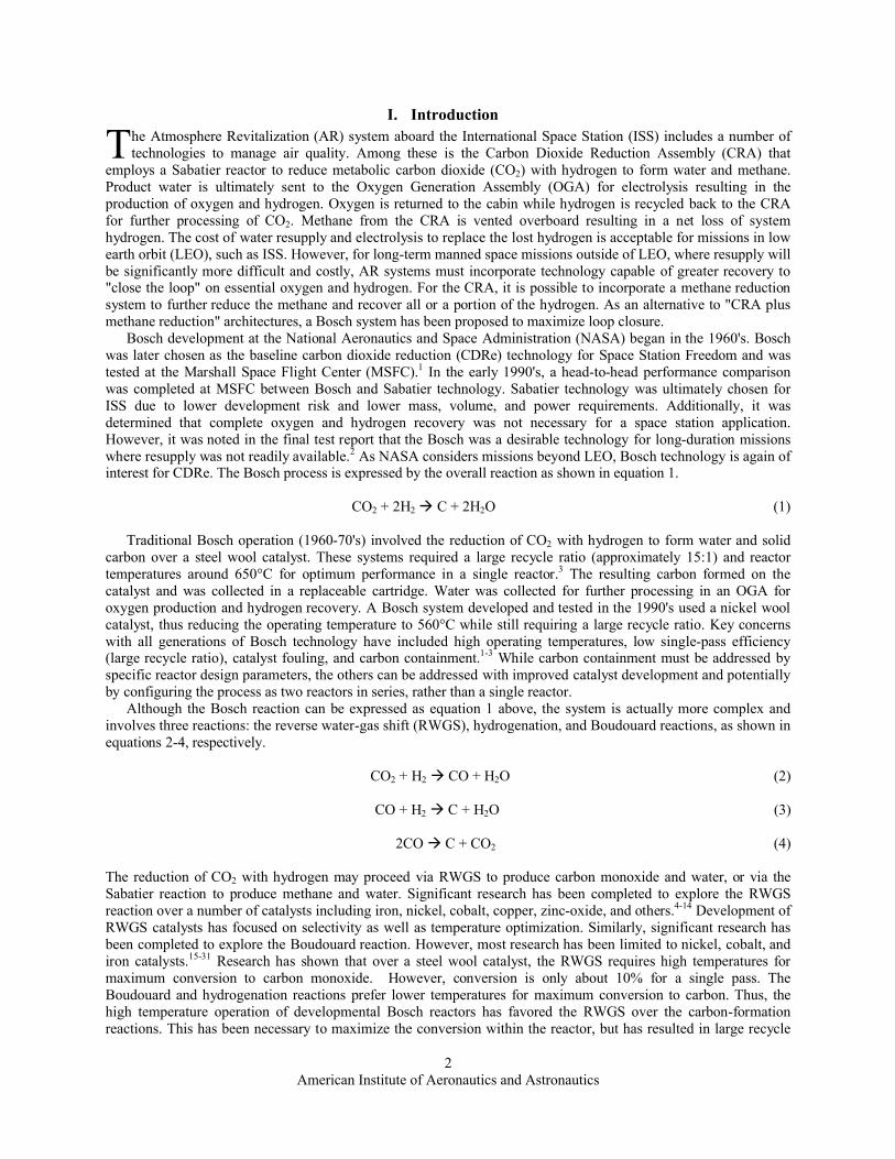
A. Horizontal Bosch (H-Bosch) Test StandThe Horizontal Bosch (H-Bosch) Test Stand, shown in Figure 1, consists of a number of component subsystems
located at the MSFC Environmental Control and Life Support Systems (ECLSS) development facility. The H-Bosch reactor system was originally developed by Life Systems, Inc. and is described in detail in another location.1 Briefly, the system is made up of two reactor assemblies, a condensing heat exchanger, a system compressor and various flow controllers, tubing, pressure transducers, thermocouples and other instrumentation necessary for operation. The reactor assemblies are custom-designed and constructed to withstand the harsh environment required to carry out the Bosch reaction. Each reactor assembly consists of a coiled tube-in-tube heat exchanger wrapped around a cylindrical reactor body. A heater sheath runs axially through the center of the reactor body to approximately three quarters of the length of the reactor. The heater sheath allows a cartridge heater to be inserted for reactor heating without exposing the heater to the internal reactor gas mixture.
Figure 1. Horizontal Bosch Test Stand. The H-Bosch is located at the Environmental Control and Life Support Systems
Development Facility at MSFC.
American Institute of Aeronautics and Astronautics4
The sheath is encircled by a thin open-ended tube resulting in a one-quarter inch annular channel between the two. After passing through the regenerative heat exchanger, feed gas flows through the channel, where additional heat is added, and out the open end into the reactor. Upon entering the reactor, gas flows radially outward through the reactor catalyst as well as axially in the direction opposite of entry. The gas exits the reactor through a ring-shaped distributor around the base of the feed tube. The hot gas must then pass counter-currently to the feed gas through the heat exchanger. A removable faceplate is located at the end of the reactor body opposite the heater. The reactor effluent stream is cooled in a condensing heat exchanger and recycled through a compressor. The product water collects in an accumulator resting on a scale, allowing water production to be monitored in near-real time. Catalyst material is packed into cylindrical cartridges designed to slip over the heater sheath and an internal thermocouple well. The catalyst cartridge sides are made of a metal mesh in order to permit gas flow. All internal surfaces of a cartridge are lined with ceramic batting before being packed with catalyst in an attempt to contain the carbon produced by the reaction. Once a cartridge is packed, it is inserted into the reactor, and the faceplate is closed and sealed.
Control is accomplished with a custom interface developed with National Instruments’ LabVIEW programming environment (Austin, TX). This control system allows for manipulation of valves and facilitates constant data collection from thermocouples, pressure transducers, and other instrumentation. Feed gases are provided from gas cylinders. Chilled water is supplied to the condensing heat exchanger by a system chiller. An Agilent micro-Gas Chromatograph (µ-GC) (Santa Clara, CA) is used to monitor gas composition. The µ-GC is programmed for continuous analysis resulting in approximately three and one-half minutes between samples. The sample location is selected from several available sites within the system using a multiport valve manufactured by Valco Instruments Company (Houston, TX). The results of each analysis are immediately delivered to the primary control system providing the capability to control recycle stream composition in near real-time by manipulating carbon dioxide and hydrogen feed rates.
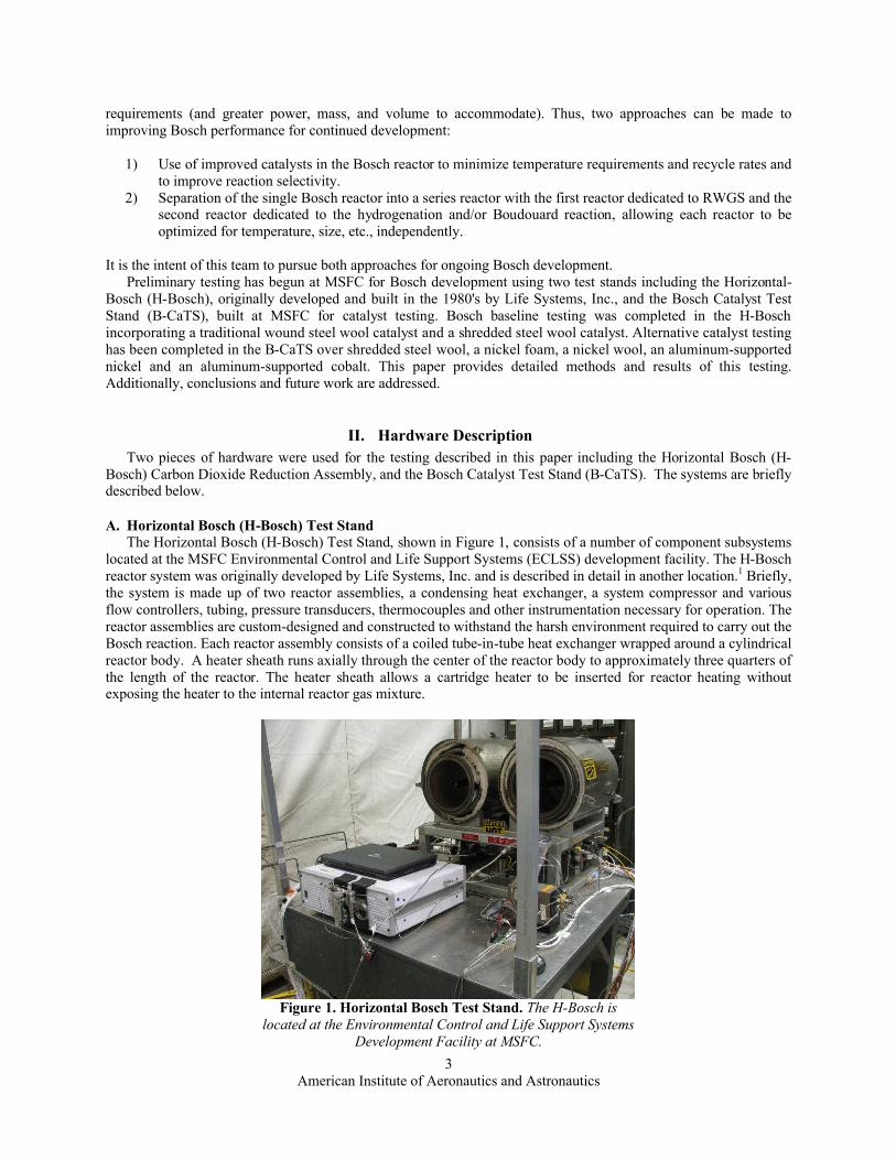
B. Bosch Catalyst Test Stand (B-CaTS)The B-CaTS, shown in Figure 2, is a scaled-
down, single-pass version of the H-Bosch that facilitates more efficient testing of Bosch catalyst properties. System feed gases pass through individual mass flow controllers and are mixed with other gases to form the reactor feed stream. Reactant gases flow through a quartz reactor tube described in detail below. The quartz reactor tube is packed with a specific mass of the catalyst under investigation. The product gas from the reactor tube is vented outside the building.
System pressure is controlled with a back pressure regulator at the reactor outlet. A vacuum pump allows the system to be operated at pressures as low as 4 psia. The maximum operating pressure is limited to 20 psia. Pressure transducers and thermocouples provide feedback for monitoring the pressure and temperature at the inlet and outlet of the reactor. A micro-Gas Chromatograph (µ-GC) (Agilent Technologies, Santa Clara, CA) is used for process gas sampling. A multi-port valve (Valco Instruments, Houston, TX) allows selection of the point within the system from which the GC sample stream is drawn. In the current configuration, only the reactor inlet and reactor outlet are sampled.
The B-CaTS reactor consists of a quartz tube with an internal diameter of 46mm and length of 610mm (National Scientific Company, Quakertown, PA). The reactor tube is inserted into a Thermolyne Basic Tube Furnace (Thermo Scientific, Waltham, MA).
Figure 2. Bosch Catalyst Test Stand. The B-CaTS provides a quartz reactor in a tube furnace for Bosch catalyst testing.
American Institute of Aeronautics and Astronautics5
When in place, the ends of the quartz tube extend beyond the sides of the furnace. Each tube end is sealed with a Vacuum Sealing Assembly (MTI Corporation, Richmond, CA), providing a connection for system tubing. The furnace is controlled by a built-in temperature control system and is capable of maintaining temperatures of 100-1200 +5°C. Pressure, temperature, gas composition, and other variables are manipulated through a custom software control interface developed within the LabVIEW programming environment (National Instruments, Austin, TX). Data acquisition is carried out via a proprietary application called PACRATS.
III. MethodsTwo separate tests conducted at the MSFC ECLSS Test Facility will be reported. The Bosch Baseline Test was
first conducted using the H-Bosch Test Stand, followed by the Alternative Catalyst Test conducted using the B-CaTS. Each test is described in detail below.
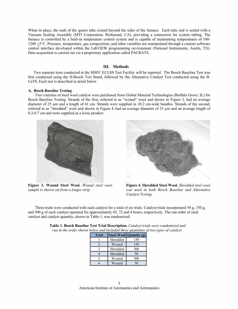
A. Bosch Baseline TestingTwo varieties of steel wool catalyst were purchased from Global Material Technologies (Buffalo Grove, IL) for
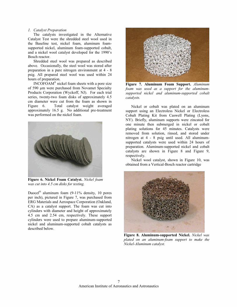
Bosch Baseline Testing. Strands of the first, referred to as “wound” wool and shown in Figure 3, had an average diameter of 25 µm and a length of 61 cm. Strands were supplied in 10.2 cm-wide bundles. Strands of the second, referred to as “shredded” wool and shown in Figure 4, had an average diameter of 25 µm and an average length of 0.3-0.7 cm and were supplied as a loose product.
Figure 3. Wound Steel Wool. Wound steel wool sample is shown cut from a longer strip.
Figure 4. Shredded Steel Wool. Shredded steel wool was used in both Bosch Baseline and Alternative Catalyst Testing.
Three trials were conducted with each catalyst for a total of six trials. Catalyst trials incorporated 50 g, 150 g, and 300 g of each catalyst operated for approximately 45, 72 and 4 hours, respectively. The run order of each catalyst and catalyst quantity, shown in Table 1, was randomized.
Table 1. Bosch Baseline Test Trial Description. Catalyst trials were randomized and run in the order shown below and included three quantities of two types of catalyst.
American Institute of Aeronautics and Astronautics6
1. Catalyst Pre-TreatmentBefore use, all steel wool catalyst was pretreated as described by Holmes et. al.3 Briefly, the catalyst was
repeatedly cleaned in a 3% hydrochloric acid solution, rinsed in de-ionized water, and baked for 45 minutes at 207°C. Catalyst was loaded into the H-Bosch cartridge immediately after removal from the oven.
2. Catalyst LoadingWithin the H-Bosch reactors, the catalyst was held in exchangeable cartridges such as the one pictured in Figure
5. Prior to loading, catalyst cartridges were lined with 1.27 cm-thick Fiberfrax (Niagara Falls, NY) Durablanket® S insulation in order to contain the product carbon inside the cartridge. For wound steel wool, the catalyst strands were spread apart by hand to increase the volume and exposed surface area. The strands were wound around the core of the cartridge. For shredded steel wool, the catalyst was distributed evenly throughout the available cartridge space. After the catalyst was loaded, two layers of insulation were placed on top of the catalyst and the cartridge lid was fixed in place with steel wire. Lastly, cartridges were installed into the H-Bosch reactor for operation.
Figure 5. H-Bosch Cartridge. The H-Bosch cartridge was lined with insulation and packed with shredded or wound steel
wool catalyst.
3. H-Bosch OperationFollowing installation of the cartridge, the reactor faceplate was attached and sealed with a gasket and v-clamp.
The system was then leak checked with CO2. A continuous purge flow of CO2 was fed to the system while the reactor was heated. H2 was introduced to the system once the reactor reached at least 290°C. Operation was assumed to be at steady-state when the reactor reached 565°C, though the target temperature was 650C. The water collection rate was verified every two hours by opening a drain valve and catching the product water in a graduated cylinder. The collected volumes were recorded at each data point. Throughout the tests, CO2 and H2 feed rates were varied slightly to maintain the maximum apparent reaction rate as determined subjectively by system pressure and temperature variations, component concentrations, and water production rate. A µ-GC was used to monitor the recycle stream during testing.
4. Cartridge RemovalAt the end of each trial, the system was purged with nitrogen and allowed to cool below 100°C. The cartridge
was removed from the reactor, opened, and photographed. Carbon and insulation material was stored for future analysis.
B. Alternative Catalyst TestingFive materials were tested for catalytic activity toward the RWGS reaction, the Boudouard reaction, and the
Hydrogenation reaction. Catalyst preparation, reactor loading, and testing are discussed below.
American Institute of Aeronautics and Astronautics7
1. Catalyst PreparationThe catalysts investigated in the Alternative
Catalyst Test were the shredded steel wool used in the Baseline test, nickel foam, aluminum foam-supported nickel, aluminum foam-supported cobalt, and a nickel wool catalyst developed for the 1990’s Bosch reactor.
Shredded steel wool was prepared as described above. Occasionally, the steel wool was stored after preparation in a pure nitrogen environment at 4 - 8 psig. All prepared steel wool was used within 24 hours of preparation.
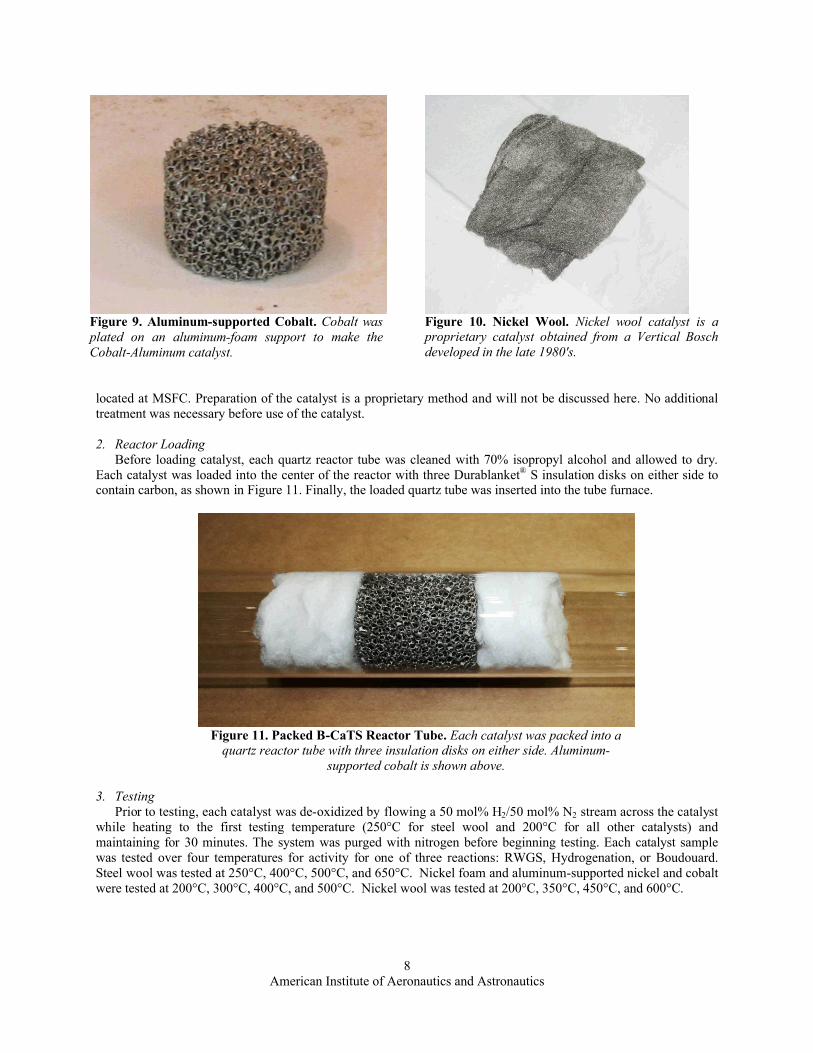
INCOFOAM® nickel foam sheets with a pore size of 590 µm were purchased from Novamet Specialty Products Corporation (Wyckoff, NJ). For each trial series, twenty-two foam disks of approximately 4.5 cm diameter were cut from the foam as shown in Figure 6. Total catalyst weight averaged approximately 16.5 g. No additional pre-treatment was performed on the nickel foam.
Figure 6. Nickel Foam Catalyst. Nickel foam was cut into 4.5 cm disks for testing.
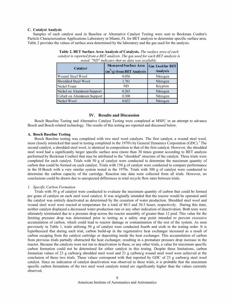
Duocel® aluminum foam (9-11% density, 10 pores per inch), pictured in Figure 7, was purchased from ERG Materials and Aerospace Corporation (Oakland, CA) as a catalyst support. The foam was cut into cylinders with diameter and height of approximately 4.5 cm and 2.54 cm, respectively. These support cylinders were used to prepare aluminum-supported nickel and aluminum-supported cobalt catalysts as described below.
Figure 7. Aluminum Foam Support. Aluminum foam was used as a support for the aluminum-supported nickel and aluminum-supported cobaltcatalysts.
Nickel or cobalt was plated on an aluminum support using an Electroless Nickel or Electroless Cobalt Plating Kit from Caswell Plating (Lyons, NY). Briefly, aluminum supports were zincated for one minute then submerged in nickel or cobalt plating solutions for 45 minutes. Catalysts were removed from solution, rinsed, and stored under nitrogen at 4 - 8 psig until used. All aluminum-supported catalysts were used within 24 hours of preparation. Aluminum-supported nickel and cobalt catalysts are shown in Figure 8 and Figure 9, respectively.
Nickel wool catalyst, shown in Figure 10, was obtained from a Vertical-Bosch reactor cartridge
Figure 8. Aluminum-supported Nickel. Nickel was plated on an aluminum-foam support to make the Nickel-Aluminum catalyst.
American Institute of Aeronautics and Astronautics8
Figure 9. Aluminum-supported Cobalt. Cobalt was plated on an aluminum-foam support to make the Cobalt-Aluminum catalyst.
Figure 10. Nickel Wool. Nickel wool catalyst is a proprietary catalyst obtained from a Vertical Bosch developed in the late 1980's.
located at MSFC. Preparation of the catalyst is a proprietary method and will not be discussed here. No additional treatment was necessary before use of the catalyst.
2. Reactor LoadingBefore loading catalyst, each quartz reactor tube was cleaned with 70% isopropyl alcohol and allowed to dry.
Each catalyst was loaded into the center of the reactor with three Durablanket® S insulation disks on either side to contain carbon, as shown in Figure 11. Finally, the loaded quartz tube was inserted into the tube furnace.
Figure 11. Packed B-CaTS Reactor Tube. Each catalyst was packed into a quartz reactor tube with three insulation disks on either side. Aluminum-
supported cobalt is shown above.
3. TestingPrior to testing, each catalyst was de-oxidized by flowing a 50 mol% H2/50 mol% N2 stream across the catalyst
while heating to the first testing temperature (250°C for steel wool and 200°C for all other catalysts) and maintaining for 30 minutes. The system was purged with nitrogen before beginning testing. Each catalyst sample was tested over four temperatures for activity for one of three reactions: RWGS, Hydrogenation, or Boudouard. Steel wool was tested at 250°C, 400°C, 500°C, and 650°C. Nickel foam and aluminum-supported nickel and cobalt were tested at 200°C, 300°C, 400°C, and 500°C. Nickel wool was tested at 200°C, 350°C, 450°C, and 600°C.
American Institute of Aeronautics and Astronautics9
C. Catalyst AnalysisSamples of each catalyst used in Baseline or Alternative Catalyst Testing were sent to Beckman Coulter's
Particle Characterization Applications Laboratory in Miami, FL for BET analysis to determine specific surface area. Table 2 provides the values of surface area determined by the laboratory and the gas used for the analysis.
Table 2. BET Surface Area Analysis of Catalysts. The surface area of each catalyst is reported from a BET analysis. The gas used for each BET analysis is
noted. "ND" indicates that no data was available.
CatalystMeasured Surface Area
(m2/g) from BET AnalysisGas Used for BET
AnalysisWound Steel Wool 0.056 NitrogenShredded Steel Wool 1.761 NitrogenNickel Foam ND KryptonNickel on Aluminum Support 0.263 NitrogenCobalt on Aluminum Support 0.300 NitrogenNickel Wool 0.022 Nitrogen
IV. Results and DiscussionBosch Baseline Testing and Alternative Catalyst Testing were completed at MSFC in an attempt to advance
Bosch and Bosch-related technology. The results of this testing are reported and discussed below.
A. Bosch Baseline TestingBosch Baseline testing was completed with two steel wool catalysts. The first catalyst, a wound steel wool,
most closely mimicked that used in testing completed in the 1970's by General Dynamics Corporation (GDC).3 The second catalyst, a shredded steel wool, is identical in composition to that of the first catalyst. However, the shredded steel wool had a significantly larger specific surface area (more than 30 times greater according to BET analysis performed by Beckman Coulter) that may be attributed to the "shredded" structure of the catalyst. Three trials were completed for each catalyst. Trials with 50 g of catalyst were conducted to determine the maximum quantity of carbon that could be formed on each catalyst. Trials with 150 g of catalyst were conducted to compare performance in the H-Bosch with a very similar system tested in the 1970s. Trials with 300 g of catalyst were conducted to determine the carbon capacity of the cartridge. Reaction rate data were collected from all trials. However, no conclusions could be drawn due to unexpected differences in total recycle flow rates between trials.
1. Specific Carbon FormationTrials with 50 g of catalyst were conducted to evaluate the maximum quantity of carbon that could be formed
per gram of catalyst on each steel wool catalyst. It was originally intended that the reactor would be operated until the catalyst was entirely deactivated as determined by the cessation of water production. Shredded steel wool and wound steel wool were reacted at temperature for a total of 40.5 and 30.5 hours, respectively. During this time, neither catalyst displayed a decreased water production rate or any other indication of deactivation. Both tests were ultimately terminated due to a pressure drop across the reactor assembly of greater than 12 psid. This value for the limiting pressure drop was determined prior to testing as a safety stop point intended to prevent excessive accumulation of carbon, which could lead to reactor damage or contamination of the rest of the system. As seen previously in Table 1, trials utilizing 50 g of catalyst were conducted fourth and sixth in the testing order. It is hypothesized that during each trial, carbon build-up in the regenerative heat exchanger increased as a result of carbon escaping from the catalyst cartridge or depositing inside the heat exchanger. This accumulation of carbon from previous trials partially obstructed the heat exchanger, resulting in a premature pressure drop increase in the reactor. Because the catalysts were not run to deactivation in these, or any other trials, a value for maximum specific carbon formation could not be determined for either catalyst in this testing. Despite these limitations, carbon formation values of 23 g carbon/g shredded steel wool and 21 g carbon/g wound steel wool were achieved at the conclusion of these two trials. These values correspond with that reported by GDC of 23 g carbon/g steel wool catalyst. Since no indication of catalyst deactivation was observed in these trials, it is probable that the maximum specific carbon formations of the two steel wool catalysts tested are significantly higher than the values currently observed.
American Institute of Aeronautics and Astronautics10
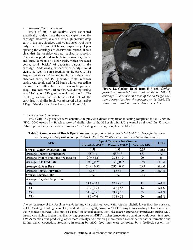
2. Cartridge Carbon CapacityTrials of 300 g of catalyst were conducted
specifically to determine the carbon capacity of the cartridge. However, due to a very high pressure drop early in the test, shredded and wound steel wool were only run for 3.8 and 4.3 hours, respectively. Upon opening the cartridges to observe the carbon, it was clear that the cartridge was not packed to capacity. The carbon produced in both trials was very loose and dusty compared to other trials, which produced dense, solid “bricks” of deposited carbon in the cartridge. Additionally, un-consumed catalyst could clearly be seen in some sections of the carbon. The largest quantities of carbon in the cartridges were observed during the 150 g catalyst trials, in which testing was conducted for 72 hours without exceeding the maximum allowable reactor assembly pressure drop. The maximum carbon observed during testing was 3166 g on 150 g of wound steel wool. The resulting carbon had to be chiseled out of the cartridge. A similar brick was observed when testing 150 g of shredded steel wool as seen in Figure 12.
Figure 12. Carbon Brick from H-Bosch. Carbon formed on shredded steel wool within a H-Bosch cartridge. The center and ends of the cartridge have been removed to show the structure of the brick. The white area is insulation embedded with carbon.
3. Performance ComparisonTrials with 150 g catalyst were conducted to provide a direct comparison to testing completed in the 1970's by
GDC. GDC operated a Bosch reactor of similar size to the H-Bosch with 150 g wound steel wool for 72 hours. Table 3 provides operation data from both GDC testing and testing completed at MSFC.
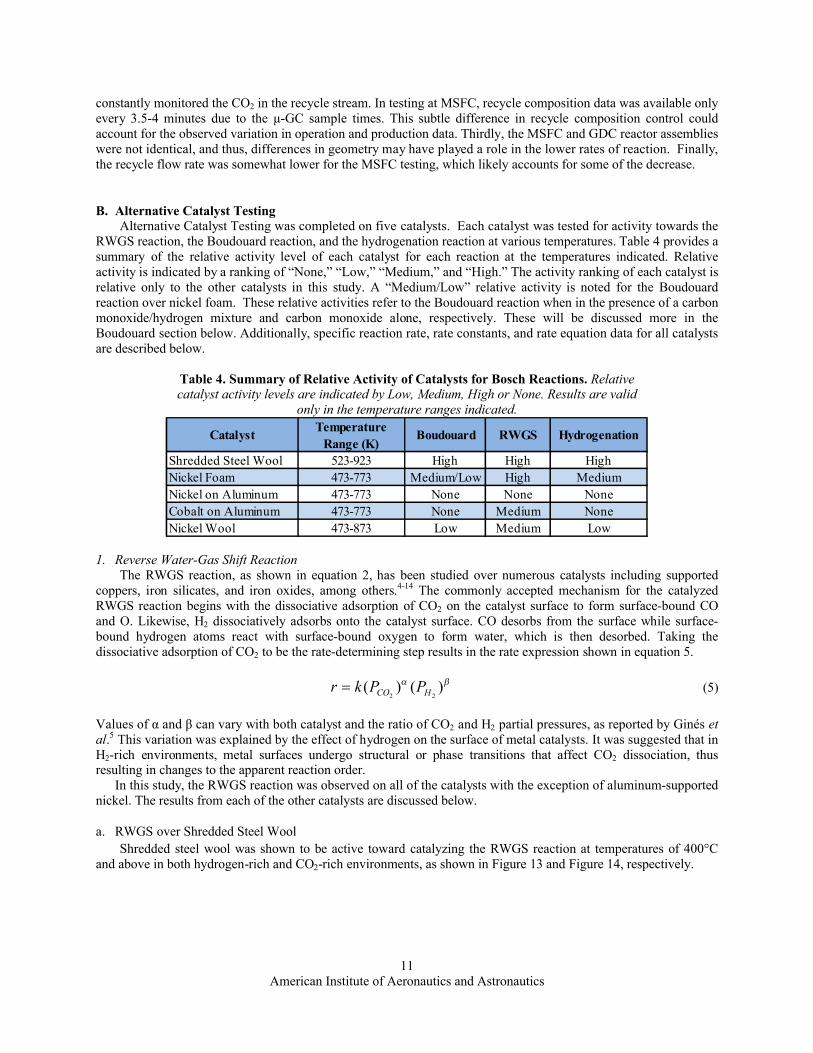
Table 3. Comparison of Bosch Operation. Bosch operation data collected at MSFC is shown for two steel wool catalysts along with data reported by GDC in the 1970's. Error shown in standard deviation.
The performance of the Bosch in MSFC testing with both steel wool catalysts was slightly lower than that observed in GDC testing. Hydrogen and CO2 feed rates were slightly lower in MSFC testing corresponding to lower observed water production rates. This may be a result of several causes. First, the reactor operating temperature during GDC testing was slightly higher than that during operation at MSFC. Higher temperature operation would result in a faster RWGS reaction thus producing water more quickly and providing more carbon monoxide for carbon formation and further water production. Secondly, in testing by GDC, feed rates were controlled by a feedback system that
American Institute of Aeronautics and Astronautics11
constantly monitored the CO2 in the recycle stream. In testing at MSFC, recycle composition data was available only every 3.5-4 minutes due to the µ-GC sample times. This subtle difference in recycle composition control could account for the observed variation in operation and production data. Thirdly, the MSFC and GDC reactor assemblies were not identical, and thus, differences in geometry may have played a role in the lower rates of reaction. Finally, the recycle flow rate was somewhat lower for the MSFC testing, which likely accounts for some of the decrease.
B. Alternative Catalyst TestingAlternative Catalyst Testing was completed on five catalysts. Each catalyst was tested for activity towards the
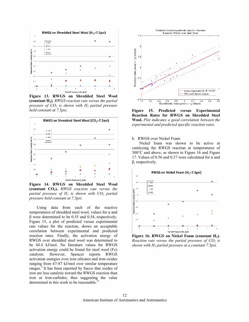
RWGS reaction, the Boudouard reaction, and the hydrogenation reaction at various temperatures. Table 4 provides a summary of the relative activity level of each catalyst for each reaction at the temperatures indicated. Relative activity is indicated by a ranking of “None,” “Low,” “Medium,” and “High.” The activity ranking of each catalyst is relative only to the other catalysts in this study. A “Medium/Low” relative activity is noted for the Boudouard reaction over nickel foam. These relative activities refer to the Boudouard reaction when in the presence of a carbon monoxide/hydrogen mixture and carbon monoxide alone, respectively. These will be discussed more in the Boudouard section below. Additionally, specific reaction rate, rate constants, and rate equation data for all catalysts are described below.
Table 4. Summary of Relative Activity of Catalysts for Bosch Reactions. Relative catalyst activity levels are indicated by Low, Medium, High or None. Results are valid
only in the temperature ranges indicated.
Catalyst Temperature Range (K)
Boudouard RWGS Hydrogenation
Shredded Steel Wool 523-923 High High HighNickel Foam 473-773 Medium/Low High MediumNickel on Aluminum 473-773 None None NoneCobalt on Aluminum 473-773 None Medium NoneNickel Wool 473-873 Low Medium Low
1. Reverse Water-Gas Shift ReactionThe RWGS reaction, as shown in equation 2, has been studied over numerous catalysts including supported
coppers, iron silicates, and iron oxides, among others.4-14 The commonly accepted mechanism for the catalyzed RWGS reaction begins with the dissociative adsorption of CO2 on the catalyst surface to form surface-bound CO and O. Likewise, H2 dissociatively adsorbs onto the catalyst surface. CO desorbs from the surface while surface-bound hydrogen atoms react with surface-bound oxygen to form water, which is then desorbed. Taking the dissociative adsorption of CO2 to be the rate-determining step results in the rate expression shown in equation 5.
)()(22 HCO PPkr (5)
Values of α and β can vary with both catalyst and the ratio of CO2 and H2 partial pressures, as reported by Ginés et al.5 This variation was explained by the effect of hydrogen on the surface of metal catalysts. It was suggested that in H2-rich environments, metal surfaces undergo structural or phase transitions that affect CO2 dissociation, thus resulting in changes to the apparent reaction order.
In this study, the RWGS reaction was observed on all of the catalysts with the exception of aluminum-supported nickel. The results from each of the other catalysts are discussed below.
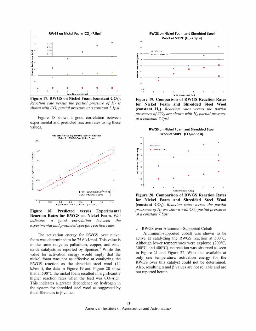
a. RWGS over Shredded Steel WoolShredded steel wool was shown to be active toward catalyzing the RWGS reaction at temperatures of 400°C
and above in both hydrogen-rich and CO2-rich environments, as shown in Figure 13 and Figure 14, respectively.
American Institute of Aeronautics and Astronautics12
Figure 13. RWGS on Shredded Steel Wool(constant H2). RWGS reaction rate versus the partial pressure of CO2 is shown with H2 partial pressure held constant at 7.5psi.
Figure 14. RWGS on Shredded Steel Wool (constant CO2). RWGS reaction rate versus the partial pressure of H2 is shown with CO2 partial pressure held constant at 7.5psi.
Using data from each of the reactive temperatures of shredded steel wool, values for α and β were determined to be 0.55 and 0.54, respectively.Figure 15, a plot of predicted versus experimental rate values for the reaction, shows an acceptablecorrelation between experimental and predicted reaction rates. Finally, the activation energy of RWGS over shredded steel wool was determined to be 44.4 kJ/mol. No literature values for RWGS activation energy could be found for steel wool (Fe) catalysts. However, Spencer reports RWGS activation energies over iron silicates and iron oxides ranging from 67-87 kJ/mol over similar temperature ranges.4 It has been reported by Sacco that oxides of iron are less catalytic toward the RWGS reaction than iron or iron-carbides, thus suggesting the value determined in this work to be reasonable.31
Figure 15. Predicted versus ExperimentalReaction Rates for RWGS on Shredded Steel Wool. Plot indicates a good correlation between the experimental and predicted specific reaction rates.
b. RWGS over Nickel FoamNickel foam was shown to be active at
catalyzing the RWGS reaction at temperatures of 300°C and above, as shown in Figure 16 and Figure 17. Values of 0.56 and 0.37 were calculated for α and β, respectively.
Figure 16. RWGS on Nickel Foam (constant H2). Reaction rate versus the partial pressure of CO2 is shown with H2 partial pressure at a constant 7.5psi.
American Institute of Aeronautics and Astronautics13
Figure 17. RWGS on Nickel Foam (constant CO2). Reaction rate versus the partial pressure of H2 is shown with CO2 partial pressure at a constant 7.5psi
Figure 18 shows a good correlation between experimental and predicted reaction rates using these values.
Figure 18. Predicted versus ExperimentalReaction Rates for RWGS on Nickel Foam. Plot indicates a good correlation between the experimental and predicted specific reaction rates.
The activation energy for RWGS over nickel foam was determined to be 75.6 kJ/mol. This value is in the same range as palladium, copper, and zinc-oxide catalysts as reported by Spencer.4 While this value for activation energy would imply that the nickel foam was not as effective at catalyzing the RWGS reaction as the shredded steel wool (44 kJ/mol), the data in Figure 19 and Figure 20 showthat at 500°C the nickel foam resulted in significantly higher reaction rates when the feed was CO2-rich. This indicates a greater dependence on hydrogen in the system for shredded steel wool as suggested by the differences in β values.
Figure 19. Comparison of RWGS Reaction Rates for Nickel Foam and Shredded Steel Wool (constant H2). Reaction rates versus the partial pressures of CO2 are shown with H2 partial pressure at a constant 7.5psi.
Figure 20. Comparison of RWGS Reaction Rates for Nickel Foam and Shredded Steel Wool (constant CO2). Reaction rates versus the partial pressures of H2 are shown with CO2 partial pressuresat a constant 7.5psi.
c. RWGS over Aluminum-Supported CobaltAluminum-supported cobalt was shown to be
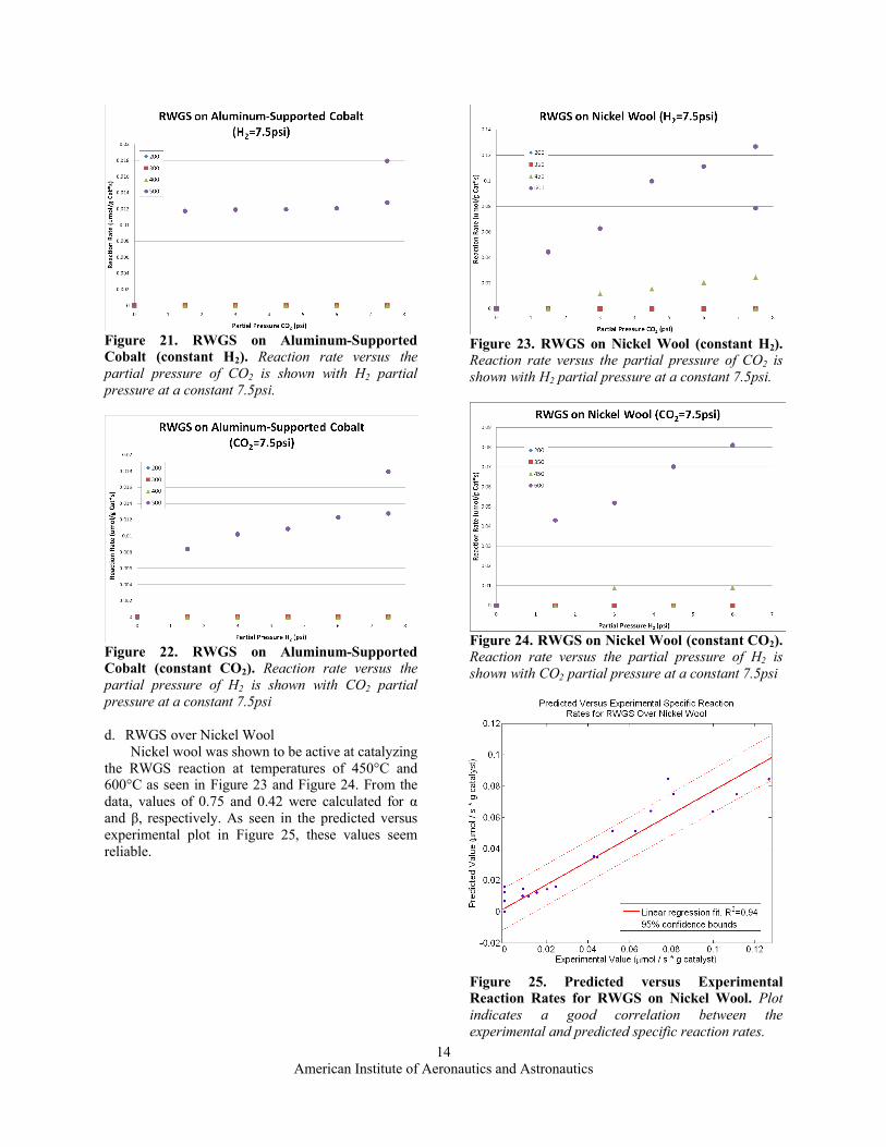
active at catalyzing the RWGS reaction at 500°C. Although lower temperatures were explored (200°C, 300°C, and 400°C), no reaction was observed as seen in Figure 21 and Figure 22. With data available at only one temperature, activation energy for the RWGS over this catalyst could not be determined. Also, resulting α and β values are not reliable and are not reported herein.
American Institute of Aeronautics and Astronautics14
Figure 21. RWGS on Aluminum-Supported Cobalt (constant H2). Reaction rate versus the partial pressure of CO2 is shown with H2 partial pressure at a constant 7.5psi.
Figure 22. RWGS on Aluminum-Supported Cobalt (constant CO2). Reaction rate versus the partial pressure of H2 is shown with CO2 partial pressure at a constant 7.5psi
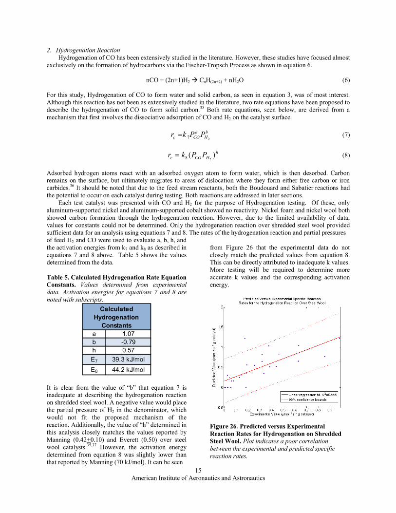
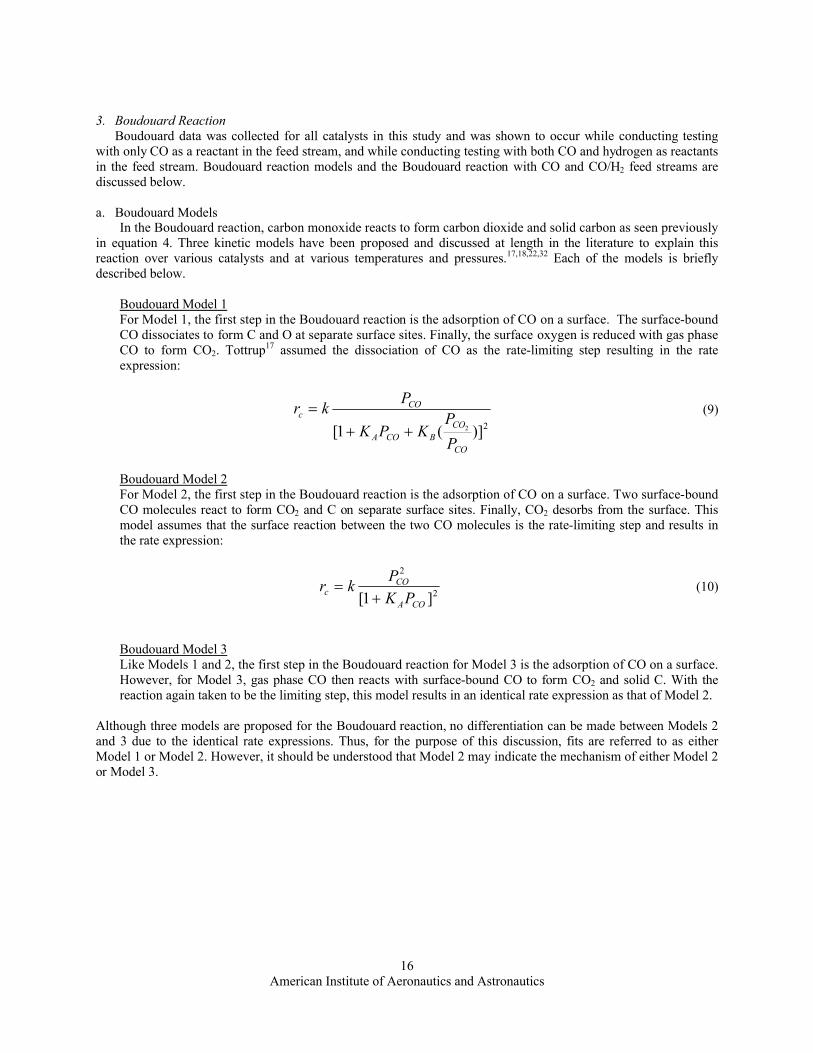
d. RWGS over Nickel WoolNickel wool was shown to be active at catalyzing
the RWGS reaction at temperatures of 450°C and 600°C as seen in Figure 23 and Figure 24. From the data, values of 0.75 and 0.42 were calculated for α and β, respectively. As seen in the predicted versus experimental plot in Figure 25, these values seem reliable.
Figure 23. RWGS on Nickel Wool (constant H2). Reaction rate versus the partial pressure of CO2 is shown with H2 partial pressure at a constant 7.5psi.
Figure 24. RWGS on Nickel Wool (constant CO2). Reaction rate versus the partial pressure of H2 is shown with CO2 partial pressure at a constant 7.5psi
Figure 25. Predicted versus ExperimentalReaction Rates for RWGS on Nickel Wool. Plot indicates a good correlation between the experimental and predicted specific reaction rates.
American Institute of Aeronautics and Astronautics15
2. Hydrogenation ReactionHydrogenation of CO has been extensively studied in the literature. However, these studies have focused almost
exclusively on the formation of hydrocarbons via the Fischer-Tropsch Process as shown in equation 6.
nCO + (2n+1)H2 CnH(2n+2) + nH2O (6)
For this study, Hydrogenation of CO to form water and solid carbon, as seen in equation 3, was of most interest. Although this reaction has not been as extensively studied in the literature, two rate equations have been proposed to describe the hydrogenation of CO to form solid carbon.35 Both rate equations, seen below, are derived from a mechanism that first involves the dissociative adsorption of CO and H2 on the catalyst surface.
bH
aCOc PPkr
27 (7)
hHCOc PPkr )(
28 (8)
Adsorbed hydrogen atoms react with an adsorbed oxygen atom to form water, which is then desorbed. Carbon remains on the surface, but ultimately migrates to areas of dislocation where they form either free carbon or iron carbides.36 It should be noted that due to the feed stream reactants, both the Boudouard and Sabatier reactions had the potential to occur on each catalyst during testing. Both reactions are addressed in later sections.
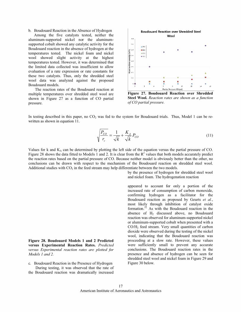
Each test catalyst was presented with CO and H2 for the purpose of Hydrogenation testing. Of these, only aluminum-supported nickel and aluminum-supported cobalt showed no reactivity. Nickel foam and nickel wool both showed carbon formation through the hydrogenation reaction. However, due to the limited availability of data, values for constants could not be determined. Only the hydrogenation reaction over shredded steel wool provided sufficient data for an analysis using equations 7 and 8. The rates of the hydrogenation reaction and partial pressuresof feed H2 and CO were used to evaluate a, b, h, and the activation energies from k7 and k8 as described in equations 7 and 8 above. Table 5 shows the values determined from the data.
Table 5. Calculated Hydrogenation Rate Equation Constants. Values determined from experimental data. Activation energies for equations 7 and 8 are noted with subscripts.
a 1.07b -0.79h 0.57E7 39.3 kJ/molE8 44.2 kJ/mol
Calculated Hydrogenation
Constants
It is clear from the value of “b” that equation 7 is inadequate at describing the hydrogenation reaction on shredded steel wool. A negative value would place the partial pressure of H2 in the denominator, which would not fit the proposed mechanism of the reaction. Additionally, the value of “h” determined in this analysis closely matches the values reported by Manning (0.42+0.10) and Everett (0.50) over steel wool catalysts.35,37 However, the activation energy determined from equation 8 was slightly lower than that reported by Manning (70 kJ/mol). It can be seen
from Figure 26 that the experimental data do notclosely match the predicted values from equation 8.This can be directly attributed to inadequate k values. More testing will be required to determine more accurate k values and the corresponding activation energy.
Figure 26. Predicted versus Experimental Reaction Rates for Hydrogenation on Shredded Steel Wool. Plot indicates a poor correlation between the experimental and predicted specific reaction rates.
American Institute of Aeronautics and Astronautics16
3. Boudouard ReactionBoudouard data was collected for all catalysts in this study and was shown to occur while conducting testing
with only CO as a reactant in the feed stream, and while conducting testing with both CO and hydrogen as reactants in the feed stream. Boudouard reaction models and the Boudouard reaction with CO and CO/H2 feed streams are discussed below.
a. Boudouard ModelsIn the Boudouard reaction, carbon monoxide reacts to form carbon dioxide and solid carbon as seen previously
in equation 4. Three kinetic models have been proposed and discussed at length in the literature to explain this reaction over various catalysts and at various temperatures and pressures.17,18,22,32 Each of the models is briefly described below.
Boudouard Model 1For Model 1, the first step in the Boudouard reaction is the adsorption of CO on a surface. The surface-bound CO dissociates to form C and O at separate surface sites. Finally, the surface oxygen is reduced with gas phase CO to form CO2. Tottrup17 assumed the dissociation of CO as the rate-limiting step resulting in the rate expression:
2)](1[ 2
CO
COBCOA
COc
PP
KPK
Pkr
(9)
Boudouard Model 2For Model 2, the first step in the Boudouard reaction is the adsorption of CO on a surface. Two surface-bound CO molecules react to form CO2 and C on separate surface sites. Finally, CO2 desorbs from the surface. This model assumes that the surface reaction between the two CO molecules is the rate-limiting step and results in the rate expression:
2
2
]1[ COA
COc PK
Pkr
(10)
Boudouard Model 3Like Models 1 and 2, the first step in the Boudouard reaction for Model 3 is the adsorption of CO on a surface. However, for Model 3, gas phase CO then reacts with surface-bound CO to form CO2 and solid C. With the reaction again taken to be the limiting step, this model results in an identical rate expression as that of Model 2.
Although three models are proposed for the Boudouard reaction, no differentiation can be made between Models 2 and 3 due to the identical rate expressions. Thus, for the purpose of this discussion, fits are referred to as either Model 1 or Model 2. However, it should be understood that Model 2 may indicate the mechanism of either Model 2 or Model 3.
American Institute of Aeronautics and Astronautics17
b. Boudouard Reaction in the Absence of HydrogenAmong the five catalysts tested, neither the
aluminum-supported nickel nor the aluminum-supported cobalt showed any catalytic activity for the Boudouard reaction in the absence of hydrogen at the temperatures tested. The nickel foam and nickel wool showed slight activity at the highest temperatures tested. However, it was determined that the limited data collected was insufficient to allow evaluation of a rate expression or rate constants for these two catalysts. Thus, only the shredded steel wool data was analyzed against the proposed Boudouard models.
The reaction rates of the Boudouard reaction at multiple temperatures over shredded steel wool are shown in Figure 27 as a function of CO partial pressure.
Figure 27. Boudouard Reaction over Shredded Steel Wool. Reaction rates are shown as a function of CO partial pressure.
In testing described in this paper, no CO2 was fed to the system for Boudouard trials. Thus, Model 1 can be re-written as shown in equation 11.
COA
c
CO Pk
Kkr
P
1 (11)
Values for k and KA can be determined by plotting the left side of the equation versus the partial pressure of CO. Figure 28 shows the data fitted to Models 1 and 2. It is clear from the R2 values that both models accurately predict the reaction rates based on the partial pressure of CO. Because neither model is obviously better than the other, no conclusions can be drawn with respect to the mechanism of the Boudouard reaction on shredded steel wool. Additional studies with CO2 in the feed stream may help differentiate between the two models.
Figure 28. Boudouard Models 1 and 2 Predicted versus Experimental Reaction Rates. Predicted versus Experimental reaction rates are plotted for Models 1 and 2.
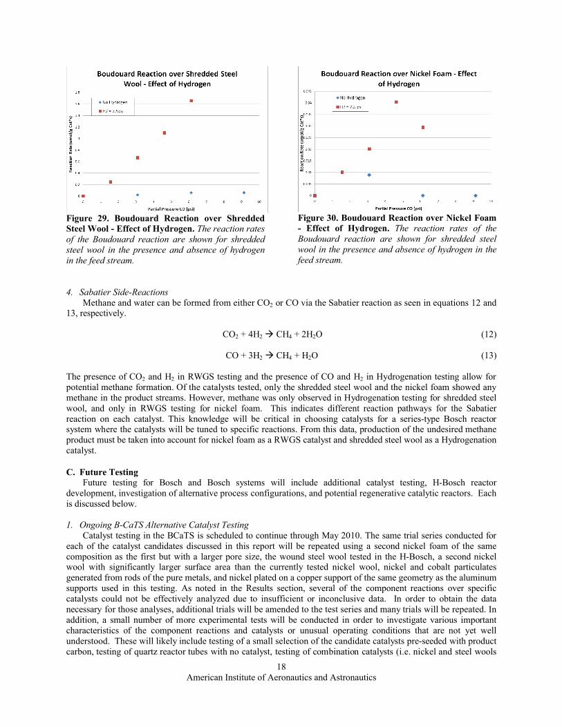
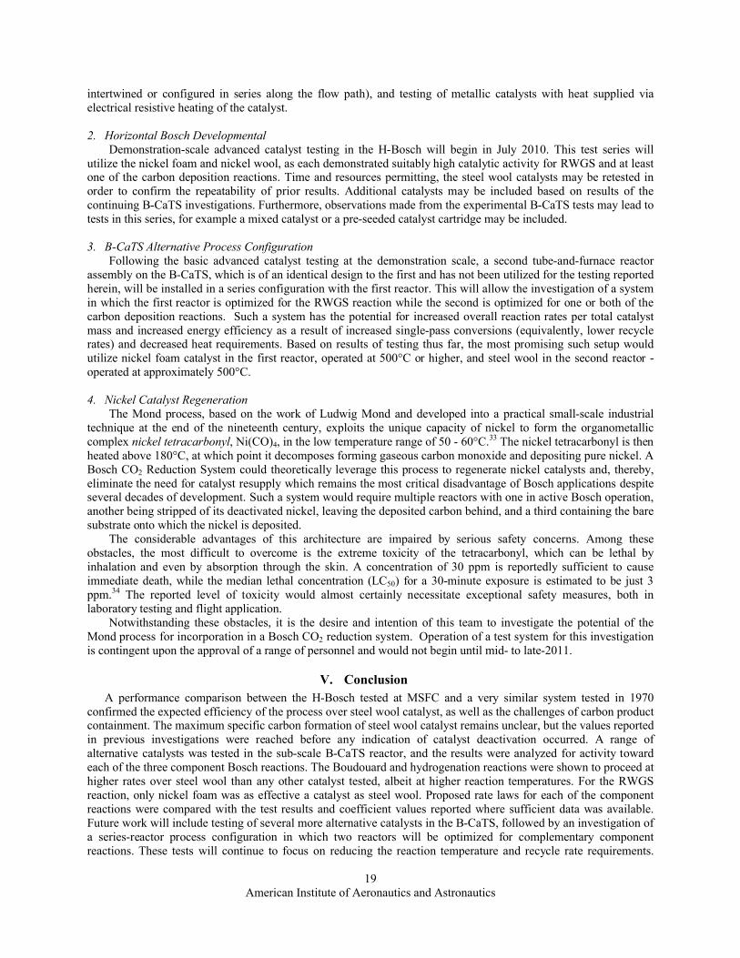
c. Boudouard Reaction in the Presence of HydrogenDuring testing, it was observed that the rate of
the Boudouard reaction was dramatically increased
by the presence of hydrogen for shredded steel wool and nickel foam. The hydrogenation reaction
appeared to account for only a portion of the increased rate of consumption of carbon monoxide, confirming hydrogen as a facilitator for the Boudouard reaction as proposed by Geurts et al., most likely through inhibition of catalyst oxide formation.32 As with the Boudouard reaction in the absence of H2 discussed above, no Boudouard reaction was observed for aluminum-supported nickel or aluminum-supported cobalt when presented with a CO/H2 feed stream. Very small quantities of carbon dioxide were observed during the testing of the nickel wool, indicating that the Boudouard reaction was proceeding at a slow rate. However, these values were sufficiently small to prevent any accurate conclusions. The Boudouard reaction rates in the presence and absence of hydrogen can be seen for shredded steel wool and nickel foam in Figure 29 and Figure 30 below.
American Institute of Aeronautics and Astronautics18
Figure 29. Boudouard Reaction over Shredded Steel Wool - Effect of Hydrogen. The reaction rates of the Boudouard reaction are shown for shredded steel wool in the presence and absence of hydrogen in the feed stream.
Figure 30. Boudouard Reaction over Nickel Foam- Effect of Hydrogen. The reaction rates of the Boudouard reaction are shown for shredded steel wool in the presence and absence of hydrogen in the feed stream.
4. Sabatier Side-ReactionsMethane and water can be formed from either CO2 or CO via the Sabatier reaction as seen in equations 12 and
13, respectively.
CO2 + 4H2 CH4 + 2H2O (12)
CO + 3H2 CH4 + H2O (13)
The presence of CO2 and H2 in RWGS testing and the presence of CO and H2 in Hydrogenation testing allow for potential methane formation. Of the catalysts tested, only the shredded steel wool and the nickel foam showed any methane in the product streams. However, methane was only observed in Hydrogenation testing for shredded steel wool, and only in RWGS testing for nickel foam. This indicates different reaction pathways for the Sabatier reaction on each catalyst. This knowledge will be critical in choosing catalysts for a series-type Bosch reactor system where the catalysts will be tuned to specific reactions. From this data, production of the undesired methane product must be taken into account for nickel foam as a RWGS catalyst and shredded steel wool as a Hydrogenation catalyst.
C. Future TestingFuture testing for Bosch and Bosch systems will include additional catalyst testing, H-Bosch reactor
development, investigation of alternative process configurations, and potential regenerative catalytic reactors. Each is discussed below.
1. Ongoing B-CaTS Alternative Catalyst TestingCatalyst testing in the BCaTS is scheduled to continue through May 2010. The same trial series conducted for
each of the catalyst candidates discussed in this report will be repeated using a second nickel foam of the same composition as the first but with a larger pore size, the wound steel wool tested in the H-Bosch, a second nickel wool with significantly larger surface area than the currently tested nickel wool, nickel and cobalt particulates generated from rods of the pure metals, and nickel plated on a copper support of the same geometry as the aluminum supports used in this testing. As noted in the Results section, several of the component reactions over specific catalysts could not be effectively analyzed due to insufficient or inconclusive data. In order to obtain the data necessary for those analyses, additional trials will be amended to the test series and many trials will be repeated. In addition, a small number of more experimental tests will be conducted in order to investigate various important characteristics of the component reactions and catalysts or unusual operating conditions that are not yet well understood. These will likely include testing of a small selection of the candidate catalysts pre-seeded with product carbon, testing of quartz reactor tubes with no catalyst, testing of combination catalysts (i.e. nickel and steel wools
American Institute of Aeronautics and Astronautics19
intertwined or configured in series along the flow path), and testing of metallic catalysts with heat supplied via electrical resistive heating of the catalyst.
2. Horizontal Bosch DevelopmentalDemonstration-scale advanced catalyst testing in the H-Bosch will begin in July 2010. This test series will
utilize the nickel foam and nickel wool, as each demonstrated suitably high catalytic activity for RWGS and at least one of the carbon deposition reactions. Time and resources permitting, the steel wool catalysts may be retested in order to confirm the repeatability of prior results. Additional catalysts may be included based on results of the continuing B-CaTS investigations. Furthermore, observations made from the experimental B-CaTS tests may lead to tests in this series, for example a mixed catalyst or a pre-seeded catalyst cartridge may be included.
3. B-CaTS Alternative Process ConfigurationFollowing the basic advanced catalyst testing at the demonstration scale, a second tube-and-furnace reactor
assembly on the B-CaTS, which is of an identical design to the first and has not been utilized for the testing reported herein, will be installed in a series configuration with the first reactor. This will allow the investigation of a system in which the first reactor is optimized for the RWGS reaction while the second is optimized for one or both of the carbon deposition reactions. Such a system has the potential for increased overall reaction rates per total catalyst mass and increased energy efficiency as a result of increased single-pass conversions (equivalently, lower recycle rates) and decreased heat requirements. Based on results of testing thus far, the most promising such setup would utilize nickel foam catalyst in the first reactor, operated at 500°C or higher, and steel wool in the second reactor -operated at approximately 500°C.
4. Nickel Catalyst RegenerationThe Mond process, based on the work of Ludwig Mond and developed into a practical small-scale industrial
technique at the end of the nineteenth century, exploits the unique capacity of nickel to form the organometallic complex nickel tetracarbonyl, Ni(CO)4, in the low temperature range of 50 - 60°C.33 The nickel tetracarbonyl is then heated above 180°C, at which point it decomposes forming gaseous carbon monoxide and depositing pure nickel. A Bosch CO2 Reduction System could theoretically leverage this process to regenerate nickel catalysts and, thereby, eliminate the need for catalyst resupply which remains the most critical disadvantage of Bosch applications despite several decades of development. Such a system would require multiple reactors with one in active Bosch operation, another being stripped of its deactivated nickel, leaving the deposited carbon behind, and a third containing the bare substrate onto which the nickel is deposited.
The considerable advantages of this architecture are impaired by serious safety concerns. Among these obstacles, the most difficult to overcome is the extreme toxicity of the tetracarbonyl, which can be lethal by inhalation and even by absorption through the skin. A concentration of 30 ppm is reportedly sufficient to cause immediate death, while the median lethal concentration (LC50) for a 30-minute exposure is estimated to be just 3 ppm.34 The reported level of toxicity would almost certainly necessitate exceptional safety measures, both in laboratory testing and flight application.
Notwithstanding these obstacles, it is the desire and intention of this team to investigate the potential of the Mond process for incorporation in a Bosch CO2 reduction system. Operation of a test system for this investigation is contingent upon the approval of a range of personnel and would not begin until mid- to late-2011.
V. ConclusionA performance comparison between the H-Bosch tested at MSFC and a very similar system tested in 1970
confirmed the expected efficiency of the process over steel wool catalyst, as well as the challenges of carbon product containment. The maximum specific carbon formation of steel wool catalyst remains unclear, but the values reported in previous investigations were reached before any indication of catalyst deactivation occurred. A range of alternative catalysts was tested in the sub-scale B-CaTS reactor, and the results were analyzed for activity toward each of the three component Bosch reactions. The Boudouard and hydrogenation reactions were shown to proceed at higher rates over steel wool than any other catalyst tested, albeit at higher reaction temperatures. For the RWGS reaction, only nickel foam was as effective a catalyst as steel wool. Proposed rate laws for each of the component reactions were compared with the test results and coefficient values reported where sufficient data was available. Future work will include testing of several more alternative catalysts in the B-CaTS, followed by an investigation of a series-reactor process configuration in which two reactors will be optimized for complementary component reactions. These tests will continue to focus on reducing the reaction temperature and recycle rate requirements.
American Institute of Aeronautics and Astronautics20
Finally, a test will be designed to evaluate the potential regeneration of nickel catalysts through the Mond process, although significant safety considerations must be taken into account prior to testing.
AcknowledgmentsThe authors would like to acknowledge the technical support of Tom Williams and David Long for software and
hardware development of the H-Bosch and B-CaTS test stands. They acknowledge Zach Greenwood for his contributions in preparing and conducting H-Bosch testing and Tony Mahathey and Curtis Leslie in B-CaTS testing. They would also like to thank Kenny Bodkin for his support of hardware development and Gena Gibbs-Dalton and Joseph Scott for catalyst preparation.
References
1Roberts, B.C., Carrasquillo, R.L., DuBiel, M.Y., Perry, J.L., Ogle, K.Y., "Space Station Freedom Environmental Control and Life Support System Phase III Simplified Integrated Test Detailed Report,” NASA Technical Memorandum-4204, 1990.
2Carrasquillo, R.L., Carter, D.L., Holder, D.W. Jr., McGriff, C.F., Ogle, K.Y., "Space Station Freedom Environmental Control and Life Support System Regenerative Subsystem Selection,” NASA Technical Memorandum-4340, 1992.
3Holmes, R.F., Keller, E.E., King, C.D., “A Carbon Dioxide Reduction Unit Using Bosch Reaction and Expendable Catalyst Cartridges,” NASA Contractor Report-1682, 1970.
4Spencer, M.S., "On the Activation Energies of the Forward and Reverse Water-Gas Shift Reaction," Catalysis Letters, Vol. 32, 1995, pp. 9-13.
5Osaki, T., Narita, N., Horiuchi, T., Sugiyama, T., Masuda, H., Suzuki, K., "Kinetics of the Reverse Water Gas Shift (RWGS) Reaction on Metal Disulfide Catalysts," Journal of Molecular Catalysis A: Chemical, Vol. 125, 1997, pp. 63-71.
6Gines, M.J.L., Marchi, A.J., Apesteguia, C.R., "Kinetic Study of the Reverse Water-Gas Shift Reaction over CuO/ZnO/Al2O3 Catalysts," Applied Catalysis A: General, Vol. 154, 1997, pp. 155-171.
7Chen, C.-S., Cheng, W.-H., Lin, S.-S., "Mechanism of CO Formation in Reverse Water-Gas Shift Reaction over Cu/Al2O3Catalyst, " Catalysis Letters, Vol. 68, 2000, pp. 45-48.
8Park, S.-W., Joo, O.-S., Jung, K.-D., Him, H., Han, S.-H., "Development of ZnO/Al2O3 Catalyst for Reverse Water-Gas-Shift Reaction of CAMERE Process," Applied Catalysis A: General, Vol. 211, 2001, pp. 81-90.
9Chen, C.-S., Cheng, W.-H., "Study on the Mechanism of CO Formation in Reverse Water Gas Shift Reaction over Cu-SiO2Catalyst by Pulse Reaction, TPD, and TPR," Catalysis Letters, Vol. 83, No. 3-4, 2002, pp. 121-126.
10Stone, F.S., Waller, D., "Cu-ZnO and Cu-ZnO/Al2O3 Catalysts for the Reverse Water-Gas Shift Reaction. The Effect of the Cu/Zn ratio on the Precursor Characteristics and on the Activity of the Derived Catalysts," Topics in Catalysis, Vol. 22, No. 3-4, 2003, pp. 305-318.
11Chen, C.-S., Cheng, W.-H., Lin, S.-S., "Study of Reverse Water Gas Shift Reaction by TPD, TPR and CO2 Hydrogenation over Potassium-Promoted Cu/SiO2 Catalyst," Applied Catalysis A: General, Vol. 238, 2003, pp. 55-67.
12Chen, C.-S, Cheng, W.-H., Lin, S.-S., "Study of Iron-Promoted Cu/SiO2 Catalyst on High Temperature Reverse Water Gas Shift Reaction," Applied Catalysis A: General, Vol. 257, 2004, pp. 97-106.
13Wang, L., Zhang, S., Liu, Y., "Reverse Water Gas Shift Reaction Over Co-Precipitated Ni-CeO2 Catalysts," Journal of Rare Earth Metals, Vol. 26, 2008, pp. 66-70.
14Kusner, R.E., "Kinetics of the Iron Catalyzed Reverse Water Gas Shift Reaction," Case Institute of Technology PhD Dissertation, 1962.
15Gregg, S.J., Leach, H.F., "Reaction of Nickel with Carbon Monoxide at Elevated Temperatures," Journal of Catalysis, Vol. 6, 1966, pp. 308-313.
16Madden, H.H., Ertl, G., "Decomposition of Carbon Monoxide on a (110) Nickel Surface," Surface Science, Vol. 35, 1973,pp. 211-226.
17Tottrup, P.B., "Kinetics of Decomposition of Carbon Monoxide on a Supported Nickel Catalyst," Journal of Catalysis, Vol. 42, 1976, pp. 29-36.
18Rosei, R., Ciccacci, F., Memeo, R., Mariani, C., Caputi, L.S., Papagno, L., "Kinetics of Carbidic Carbon Formation from CO in the 10-6 Torr Range on Ni(110)," Journal of Catalysis, Vol. 83, 1983, pp. 19-24.
19Kuijpers, E.G.M., Kock, A.J.H.M., Nieuwesteeg, M.W.C.M.A., Geus, J.W., "Disproportionation of CO on Ni/SiO2: Kinetics and Nature of the Deposited Carbon," Journal of Catalysis, Vol. 95, 1985, pp. 13-20.
20Chen, P., Zhang, H.-B., Lin, G.-D., Hong, Q., Tssai, K.R., "Growth of Carbon Nanotubes by Catalytic Decomposition of CH4 or CO on a Ni-MgO Catalyst," Carbon, Vol. 35, No. 10-11, 1997, pp. 1495-1501.
21Zielinski, J., "Interaction of Carbon Monoxide with Supported Nickel Catalysts," Journal of Molecular Catalysis, Vol. 79, 1993, pp. 187-198.
22Tavares, M.T., Alstrup, I., Bernardo, C.A., Rostrup-Bielsen, J.R., "CO Disproportionation on Silica-Supported Nickel and Nickel-Copper Catalysts," Journal of Catalysis, Vol. 147, 1994, pp. 525-534.
23Thess, A. et al., "Crystalline Ropes of Metallic Carbon Nanotubes," Science, Vol. 273, 1996, pp. 483-487.
American Institute of Aeronautics and Astronautics21
24Dai, H., Rinzler, A.G., Nikolaev, P., Thess, A., Colbert, D.T., Smalley, R.E., "Single-Wall Nanotubes Produced by Metal-Catalyzed Disproportionation of Carbon Monoxide," Chemical Physics Letters, Vol. 260, 1996, pp. 471-475.
25Govindaraj, A., Sen, R., Santra, A.K., Nagaraju, B.V., "Carbon Structures Obtained by the Disproportionation of Carbon Monoxide over Nickel Catalysts," Materials Research Bulletin, Vol. 33, No. 4, 1998, pp. 663-667.
26Cheng, H., Reiser, D.B., Dean, S.Jr., "On the Mechanism of Energetics of the Boudouard Reaction at FeO(1 0 0) Surface: 2CO→ C + CO2," Catalysis Today, Vol. 50., 1999, pp. 579-588.
27Pinheiro, J.P., Gadelle, P., "Chemical State of Supported Iron-Cobalt Catalyst During CO Disproportionation I. Thermodynamic Study," Journal of Physics and Chemistry of Solids, Vol. 62, 2001, pp. 1015-1021.
28Pinheiro, J.P., Gadelle, P., Jeandey, C., Oddou, J.L., "Chemical State of Supported Iron-Cobalt Catalyst During CO Disproportionation II. Experimental Study," Journal of Physics and Chemistry of Solids, Vol. 62, 2001, pp. 1023-1037.
29Essenhigh, K.A., Utkin, Y.G., Bernard, C., Adamovich, I.V., Rich, J.W., "Gas-Phase Boudouard Disproportionation Reaction Between Highly Vibrationally Excited CO Molecules," Chemical Physics, Vol. 330, 2006, pp. 506-514.
30Serdyuchenko, A., Mintusov, E., Frederickson, K., Lempert, W.R., Rich, J.W., Adamovich, I.V., "Isotope Effect in Boudouard Disproportionation Reaction in Optically Pumped CO," Chemical Physics, Vol. 363, 2009, pp. 24-32.
31Sacco, Albert Jr., “An Investigation of the Reactions of Carbon Dioxide, Carbon Monoxide, Methane, Hydrogen, and Water Over Iron, Iron Carbides, and Iron Oxides,” Massachusetts Institute of Technology Dissertation, 1977.
32Geurts, F.W.A.H., Sacco, A. Jr., ”The Relative Rates of the Boudouard Reaction and Hydrogenation of CO over Fe and Co Foils,” Carbon, Vol. 30, No. 3, 1992, pp. 415-418.
33Mond, L.C., Langer, C., Quinke, F., “Action of Carbon Monoxide on Nickel,”Journal of Chemical Society, Vol. 57, 1890, pp.749-755.
34Board on Environmental Studies and Toxicology, “Nickel Carbonyl: Acute Exposure Guideline Levels,” Acute Exposure Guideline Levels for Selected Airborne Chemicals, National Academies Press, Vol. 6, 2008, pp. 213-259.
35Manning, M.P., “An Investigation of the Bosch Process,” Massachusetts Institute of Technology Dissertation, 1976.36Walker, P.L.Jr., Rakszawski, J.F., Imperial, G.R., “Carbon Formation from Carbon Monoxide-Hydrogen Mixtures over
Iron Catalysts. II. Rates of Carbon Formation,” Journal of Physical Chemistry, Vol. 63, 1959, pp. 140-149.37Everett, M.R., “The Kinetics of Carbon Deposition Reactions in High-Temperature Gas-Cooled Reactors,” D.P.Report 500,