J.P.Delahaye CLIC @ SAC seminar (03/09/10) 1 Helsinki Institute of Physics (Finland) IAP (Russia) IAP NASU (Ukraine) IHEP (China) INFN / LNF (Italy) Instituto de Fisica Corpuscular (Spain) IRFU / Saclay (France) Jefferson Lab (USA) John Adams Institute/Oxford (UK) Polytech. University of Catalonia (Spain) PSI (Switzerland) RAL (UK) RRCAT / Indore (India) SLAC (USA) Thrace University (Greece) Tsinghua University (China) University of Oslo (Norway) Uppsala University (Sweden) UCSC SCIPP (USA) ACAS (Australia) Aarhus University (Denmark) Ankara University (Turkey) Argonne National Laboratory (USA) Athens University (Greece) BINP (Russia) CERN CIEMAT (Spain) Cockcroft Institute (UK) ETHZurich (Switzerland) Gazi Universities (Turkey) John Adams Institute/RHUL (UK) JINR/Dubna (Russia) Karlsruhe University (Germany) KEK (Japan) LAL / Orsay (France) LAPP / ESIA (France) NIKHEF/Amsterdam (Netherland) NCP (Pakistan) North-West. Univ. Illinois (USA) Patras University (Greece) Towards CLIC feasibility J.P.Delahaye for the CLIC collaboration CLIC multi-lateral Collaboration 40 volunteer Institutes from 21 Countries Reminder of CLIC objectives and scheme CLIC feasibility issues R&D program, status and plans ISTC and Russian Institutes contributions Preparation of Conceptual Design Report Outlook to the future Conclusion
Transcript
J.P.Delahaye CLIC @ SAC seminar (03/09/10) 1
Helsinki Institute of Physics (Finland)IAP (Russia)IAP NASU (Ukraine)IHEP (China)INFN / LNF (Italy)Instituto de Fisica Corpuscular (Spain)IRFU / Saclay (France)Jefferson Lab (USA)John Adams Institute/Oxford (UK)
Polytech. University of Catalonia (Spain)PSI (Switzerland)RAL (UK)RRCAT / Indore (India)SLAC (USA)Thrace University (Greece)Tsinghua University (China)University of Oslo (Norway)Uppsala University (Sweden)UCSC SCIPP (USA)
ACAS (Australia)Aarhus University (Denmark)Ankara University (Turkey)Argonne National Laboratory (USA)Athens University (Greece)BINP (Russia)CERNCIEMAT (Spain)Cockcroft Institute (UK)ETHZurich (Switzerland)Gazi Universities (Turkey)
John Adams Institute/RHUL (UK)JINR/Dubna (Russia)Karlsruhe University (Germany)KEK (Japan) LAL / Orsay (France) LAPP / ESIA (France)NIKHEF/Amsterdam (Netherland) NCP (Pakistan)North-West. Univ. Illinois (USA)Patras University (Greece)
Towards CLIC feasibilityJ.P.Delahaye for the CLIC collaboration
CLIC multi-lateral Collaboration40 volunteer Institutes from 21 Countries
Reminder of CLIC objectives and schemeCLIC feasibility issuesR&D program, status and plansISTC and Russian Institutes contributions Preparation of Conceptual Design Report Outlook to the futureConclusion
J.P.Delahaye CLIC @ SAC seminar (03/09/10) 2
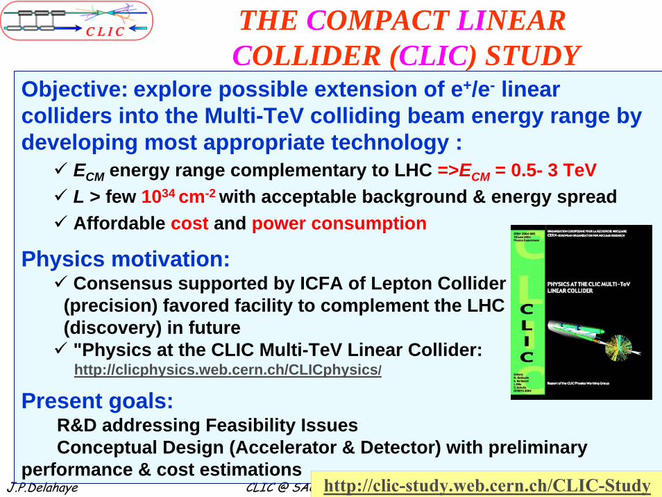
Objective: explore possible extension of e+/e- linear colliders into the Multi-TeV colliding beam energy range by developing most appropriate technology :
ECM energy range complementary to LHC =>ECM = 0.5- 3 TeVL > few 1034 cm-2 with acceptable background & energy spreadAffordable cost and power consumption
Physics motivation:Consensus supported by ICFA of Lepton Collider
(precision) favored facility to complement the LHC(discovery) in future"Physics at the CLIC Multi-TeV Linear Collider:http://clicphysics.web.cern.ch/CLICphysics/
• Beam acceleration: MW of beam power with high gradient and high efficiency• Generation of ultra-low emittances: micron rad-m in H, nano rad-m in V• Preservation of low emittances in strong wake field environment
Hor./vert. IP beam size (nm) 202 / 2.3 40 / 1Hadronic events/crossing at IP 0.19 2.7Coherent pairs at IP 100 3.8 108
Wall plug to beam transfer eff 7.5% 6.8%Total power consumption (MW) 129.4 415
J.P.Delahaye CLIC @ SAC seminar (03/09/10) 8
CLIC critical issuesR&D strategy and schedule
Critical issues classified in three categories: Risk registerhttps://edms.cern.ch/nav/CERN-0000060014/AB-003093
• CLIC design and technology feasibilityFully addressed by specific R&D with results in Conceptual Design Report (CDR) including preliminary Performance & Cost by 2011
• Performance and/or Cost Both being addressed now by specific R&D to be completed with results in Technical Design Report (TDR) including consolidated Performance & Cost tentatively by 2016 (?)
Two Beam Test Stand Probe BeamDrive and probe beamsin CLEX from June 2008
CTF3/CLEX (CLIC Experimental Area)Test beam line (TBL) to study RF power production (1.5 TW at 12 GHz) and drive beam decelerator dynamics, stability & losses - Two Beam Test Stand to study probe beam acceleration with high fields at high frequency and the feasibility of Two Beam modules
J.P.Delahaye CLIC @ SAC seminar (03/09/10) 14
Power Production Structure (PETS )design, built @ CERN, power tests @ CTF3, SLAC
Drive beam driven @ CTF3
Klystron driven @ SLAC
CLIC target
266 ns(240 ns CLIC target)CLIC target
CLIC targetCLIC target
CLICtarget
J.P.Delahaye CLIC @ SAC seminar (03/09/10) 15
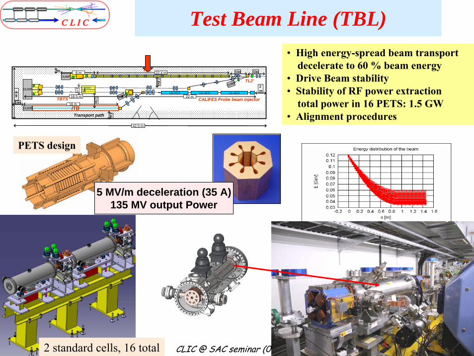
Test Beam Line (TBL)• High energy-spread beam transport
decelerate to 60 % beam energy• Drive Beam stability• Stability of RF power extraction
total power in 16 PETS: 1.5 GW• Alignment procedures
PETS design
42.5 m
8 m
2m
D FFD
DF
F
D F DDUMPD F D
F
FD
ITB
1.85m
CALIFES Probe beam injectorLIL-ACSLIL-ACSLIL-ACSD F D
D F D
DFDUMP
0.75
1.4m
1
DUMP
22.4 mTBL
2.5m
Transport path
DUMP
DUMP 22 m2.0m
DF DF DF DF DF DF DF DF
3.0m3.0m6 m
D F DF DF D
16.5 mTBTS16 m
TL2’
42.5 m42.5 m
8 m8 m
2m2m
D FFFDD
DF
FDD
FF
FF
D F DD F DDUMPD F DD F D
F
FD
F
FD
F
FD
ITB
1.85m1.85m
CALIFES Probe beam injectorLIL-ACSLIL-ACSLIL-ACSLIL-ACSLIL-ACSLIL-ACSD F DD F D
Accelerating sections RF deflector for diagnostics
waveguide RF distribution
J.P.Delahaye CLIC @ SAC seminar (03/09/10) 18
Two Beam Test Stand (TBTS)in CTF3/CLEX
All hardware installed! Beam in both lines up to end !Commissioning with beam: PETS 2009, Two Beam Acceleration 2010
J.P.Delahaye CLIC @ SAC seminar (03/09/10) 19
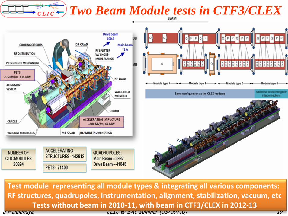
Two Beam Module tests in CTF3/CLEX
19G. Riddone
Test module representing all module types & integrating all various components: RF structures, quadrupoles, instrumentation, alignment, stabilization, vacuum, etc
Tests without beam in 2010‐11, with beam in CTF3/CLEX in 2012‐13
J.P.Delahaye CLIC @ SAC seminar (03/09/10) 20
Russian contribution to CLIC/CTF3For Combiner Ring (JINR/DUBNA):
11 quadrupole magnets26 sextupole magnets for Combiner Ring
For TBTS (IAP/GYCOM):variable attenuatorvariable phase shifter
For TBL (IAP/GYCOM) : one test PETS bar, ongoing qualification process
For Stand-alone 12 GHz power source (IAP/GYCOM) : pulse compressor
For 30 GHz test stand (IAP/GYCOM) :low-loss transmission line30 GHz gyroklystron
For Photo-Injector (IAP/GYCOM) : Laser developments
For CLIC Damping Ring (BINP): SC wiggler magnet prototype
J.P.Delahaye CLIC @ SAC seminar (03/09/10) 21
JINR/Dubna contribution to CLIC RF developments
8 JINR experts at CERN:Engineering design of RF structures and RF
componentsTwo-beam module design and integrationQuality control, assembly and installation of RF
structures and componentsImplementation of quality assurance system for RF
structures and componentsFollow-up of the fabrication of RF componentsLogistics for RF structures and components Software development for LHC and SPS RF system
J.P.Delahaye CLIC @ SAC seminar (03/09/10) 22
JINR/Dubna contribution toCLIC Magnet System R&D Program
2 Project Associates (A.Vorozhtsov and E.Solodko) from JINR (Dubna) joined CERN in 2009. They are working on different fronts of CLIC Magnet System R&D program:
• Designing (magnetic and mechanical) magnet prototypes for CLIC and CLEX test program (Main Beam and Drive Beam quadrupoles, correctors, etc.).• Designing an Hybrid (Permanent + electro-magnetic design) quadrupole model for the Final Focus doublet.• “General Catalogue of CLIC Magnets”:
Evaluation of the CLIC magnets in terms of main working parameters for a first estimation of procurement and running costs (power, cooling, etc.).
Further contribution on the magnet R&D Program welcome in the future on dedicated subsystem analysis and design or on industrialization studies (ex. manufacturing studies for big series of magnets).
J.P.Delahaye CLIC @ SAC seminar (03/09/10) 23
•Since 2003, the successful collaboration between CLIC/CERN and IAP/GYCOM, brought very important contributions to the CLIC experimental program.
A number of unique RF devices were proposed, design and fabricated in IAP/GYCOM (Nizhniy Novgorod, Russia).
Practically all of them were installed and are used routinely now in the different parts of the CTF3 complex.
•We are looking forward to increase the existing collaboration in a future, especially in the fields where IAP/GYCOM expertise is worldwide recognized:
High power RF components and systems.Devices for active control of the RF high power signals
(phase and amplitude).RF high power sources.
IAP contribution to developments of RF components
J.P.Delahaye CLIC @ SAC seminar (03/09/10) 24
30 GHz RF componentsdeveloped in IAP/GYCOM for CLIC.
The special low-losses Transfer Line, fabricated in GYCOM, provided high power transport (up to 160 MW x 70 ns) with efficiency ~ 87% at a distance of 17 meters.
J.P.Delahaye CLIC @ SAC seminar (03/09/10) 25
30 GHz RF componentsdeveloped in IAP/GYCOM for CLIC.
Distance, mm
Phas
e, ra
dian
π
-π0 10 20 30 40 50
00
Distance, mm
Phas
e, ra
dian
π
-π0 10 20 30 40 50
00
Laser
RF in
RF outThe fast (few ns) active high power RF phase switch (0-1800), capable to operate at 100 MW RF peak power level was designed and fabricated in GYCOM.
J.P.Delahaye CLIC @ SAC seminar (03/09/10) 26
Variable high power RF power splitter
Variable high power RF phase shifter
S parameters at the position of the max (blue) and min (red) coupling of the power splitter
11.7 11.8 11.9 12 12.1 12.230
20
10
0
Frequency,GHz
S12,
dB
20−
F
50 db directional couplers
The RF components fabricated by GYCOM: directional couplers, variable splitter and phase shifter have been installed and now under operation in the TBTS, CLEX at CERN.
12 GHz RF componentsdeveloped in IAP/GYCOM for CLIC.
J.P.Delahaye CLIC @ SAC seminar (03/09/10) 27
J.P.Delahaye CLIC @ SAC seminar (03/09/10) 28
J.P.Delahaye CLIC @ SAC seminar (03/09/10) 29
J.P.Delahaye CLIC @ SAC seminar (03/09/10) 30
Ultra low Beam Emittance Generation• Key parameter to achieve high luminosity with limited beam (and wall plug) power
• CLIC requirements close to new generation synchrotron light sources (Operation- Projects)
• CLIC 500 GeV similar as ILC and demonstrated in ATF/KEK (normalized emittance)
• CLIC 3 TeV similar as PEPX/SLAC project.
• Close collaboration with ATF/KEK (small emittances) and CESRTA/Cornell (electron clouds)
J.P.Delahaye CLIC @ SAC seminar (03/09/10) 31
CERN/ANKA SCwiggler
BINP SCwiggler
BINP PMwiggler
Parameters BINPCERN/Karlsruhe
Bpeak [T] 2.5 2.8
λW [mm] 50 40
Beam aperture full gap [mm] 13 13
Conductor type NbTi NbSn3
Operating temperature [K] 4.2 4.2
CLICdesign
Energy [GeV] 2.86
Circumference [m] 493.05
Number of arc cells 100
Number of wigglers 76
RF voltage [MV] 6.5
Damping time x / s [ms] 1.87 / 0.94
IBS growth factor 2.0
Hor. Norm. Emittance [nm.rad] 480
Ver. Norm. Emittance [nm.rad] 4.7
Bunch length [mm] 1.4
Longitudinal emittance [eVm] 3700
CLIC DR based on SC Wigglers
J.P.Delahaye CLIC @ SAC seminar (03/09/10) 32
J.P.Delahaye CLIC @ SAC seminar (03/09/10) 33
Nb3Sn Nb-Ti
CDR
TDRSCU14 in ANKA
20122013
End 2010
J.P.Delahaye CLIC @ SAC seminar (03/09/10) 34
J.P.Delahaye CLIC @ SAC seminar (03/09/10) 35
CLIC Tentative Schedule
ConceptualDesign Report
(CDR)
TechnicalDesign Report
(TDR) ?
CLIC CDR andCLIC TDP proposal
@ CERN Council
European Strategyfor Particle Physics@ CERN Council
J.P.Delahaye CLIC @ SAC seminar (03/09/10) 36
Extremely fruitfulCLIC /ILC Collaboration
• ILC for a TeV LC based on SC RF technology & CLIC extending LC into Multi-TeV range complementary.• Common working groups on technical subjects with strong synergy between CLIC & ILC
• making the best use of the available resources
• developing common knowledge of both designs and technologies on status, advantages, issues and prospects• preparing together by the Linear Collider Community made up of CLIC & ILC experts:
• proposal(s) best adapted to the future HEP requirements
Joint CLIC & ILC workshop (October 18-22 @ CERN) (IWLC10: Linear Collider Accelerator and Detectors)
J.P.Delahaye CLIC @ SAC seminar (03/09/10) 37
Conclusion• Novel CLIC technology to extend Linear Colliders into the Multi-TeV energy range with promising performances and challenging parameters• R&D on feasibility issues and concept of 3 TeV multi-TeV Linear collider in a Conceptual Design Report (CDR) by mid 2011
• Ambitious Test Facilities: CTF3, ATF1,2, CESR-TA…• Exploration to determine LC capabilities & limitations in multi-TeV range
• Technical design phase (about six years depending on resources):• engineering design optimization, technological risks & cost mitigation
• Linear collider energy, luminosity and appropriate technology to be defined as the best trade-off following:
• Physics requirements when better known from LHC/Tevatron results• Design performances, technology risk, power consumption and cost
Warm thanks to outstanding contributions of CLIC collaborationspecially Russian Institutes and ISTC support
in the past, present and …. Future,Welcome extension of collaboration with Russian Institutes with
expertise specially adapted to Technical Design Phasetechnical development & industrialization of key components or sub-
systems
J.P.Delahaye CLIC @ SAC seminar (03/09/10) 38
Spares
J.P.Delahaye CLIC @ SAC seminar (03/09/10) 39
Drive Beam GenerationBeam
Intensity &Frequency
multiplicationX 24
62.5 GeV- 880m
J.P.Delahaye CLIC @ SAC seminar (03/09/10) 40
The CLIC Main Beam Generation
e gun-
3 TeV
Base line configuration
Unpolarised positrons
Laser
-
Pre-injector Linac for e-
200 MeV
-Pre-injector Linac for e+
200 MeV
Primary beam Linac for e-
5 GeV
Inje
ctor
Lin
ac
2.2
GeV
DC gunPolarized e
e /gTarget
e+ DR
e+ PDRB
oost
er L
inac
6.
6 G
eV 4 GHz
e+ BC1 e- BC1
e+ BC2 e- BC2e+ Main Linac e- Main Linac
2 GHz
e- DR
e- PDR
2 GHz 2 GHz 2 GHz
4 GHz 4 GHz
12 GHz12 GHz
9 GeV48 km
� 30 m � 30 m
2.424 GeV 2.424 GeV
g/e+
Target
AMD
473 m
2.424 GeV365 m 2.424 GeV
365 m
228 m
365 m365 m
J.P.Delahaye CLIC @ SAC seminar (03/09/10) 41
CLIC performances (FoM) and cost (relative) as a function of the accelerating gradient
• Performances increasing with lower accelerating gradient (mainly due to higher efficiency)• Flat cost variation in 100 to 130 MV/m with a minimum around 120 MV/m
Ecms = 3 TeV L(1%) = 2.0 1034 cm-2s-1
Previous PreviousNew New Optimum
Figure of MeritPerformance
Cost
J.P.Delahaye CLIC @ SAC seminar (03/09/10) 42
CLIC performances (FoM) and cost optimisationas function of RF frequency
Ecms = 3 TeV L(1%) = 2.0 1034 cm-2s-1
• Maximum Performance around 14 GHz • Flat cost variation in 12 to 16 GHz frequency range with a minimum around 14 GHz
New NewPrevious PreviousOptimumOptimum
Performance Cost
J.P.Delahaye CLIC @ SAC seminar (03/09/10) 43
Relative cost of Linear Colliders
LC
CLIC
0
0 .5
1
1 .5
2
2 .5
3
3 .5
0 0 .2 0 .4 0 .6 0 .8 1 1 .2
Energy (arbitrary scale)
Cos
t (ar
bitr
ary
scal
e
Additional CLIC offsetdue to drive beam injectors
Reduced CLIC cost/GeV due to- reduced tunnel length (by 4)
- reduced equipment per meter of tunnel
J.P.Delahaye CLIC @ SAC seminar (03/09/10) 44
CLIC feasibility issues
J.P.Delahaye CLIC @ SAC seminar (03/09/10) 45
28 MW
Main beam injection, magnets, services, infrastructure
and detector
Dumps
Mainlinac
PETS
Drive beamacceleration
252.6 MW
148.0 MW 1 GHz RF power
137.4 MW Drive Beam Power
107.4 MW
13.7 MW ηplug/RF = 38.8 %
ηM = .90
ηA = .977
ηTRS = .98ηT = .96
F(σ) = .97 × .96ηD = .84
Drive beampower extr.
Power suppliesklystrons
ηRF/main = 27.7 %
ηtot = 6.8 %
ηS = .95
ηRF = .277
101.1 MW 12 GHz RF power (2 x 101 kJ x 50 Hz)
Main beam
Wall Plug
ηK = .70
415 MWModulator auxiliaries
260.4 MW AC power
ηREL = .93aux = 0.97
154.6 MW
Power flow @ 3 TeV
J.P.Delahaye CLIC @ SAC seminar (03/09/10) 46
Accelerating Structure Performances
Accelerating Structure Performances
ILC design1.3 GHz
Pulsed SC
SLC operation3 GHz
Single bunch
NLC design11.4 GHz
CLIC design3 TeV
CLIC design500 GeV
T18vg2.412GHz
No dampingMeasured
0.00
5.00
10.00
15.00
20.00
25.00
30.00
35.00
40.00
0.00 20.00 40.00 60.00 80.00 100.00 120.00
Loaded Average Accelerating Field (MV/m)
RF
to b
eam
Effic
ienc
y te
mp
stab
ilise
d (%
)
World recordAccelerating GradientMulticell Structures
(no damping yet)
Accelerating Structure Performances
LEPCW SC
ILC design1.3 GHz
Pulsed SC
SLC operation3 GHz
Single bunch
NLC design11.4 GHz
CTF3 Drive beam
Fully loaded3GHz
CLIC design3 TeV
CLIC design500 GeV
T18vg2.412GHz
No dampingMeasured
0.00
10.00
20.00
30.00
40.00
50.00
60.00
70.00
80.00
90.00
100.00
0.00 20.00 40.00 60.00 80.00 100.00 120.00
Loaded Average Accelerating Field (MV/m)
RF
to b
eam
Effic
ienc
y te
mp
stab
ilise
d (%
)
World recordAccelerating Gradient
World recordRF to beam efficiency
J.P.Delahaye CLIC @ SAC seminar (03/09/10) 47
Achieved results to prototype CLIC structure
T18 test structure CLIC prototype
J.P.Delahaye CLIC @ SAC seminar (03/09/10) 4848
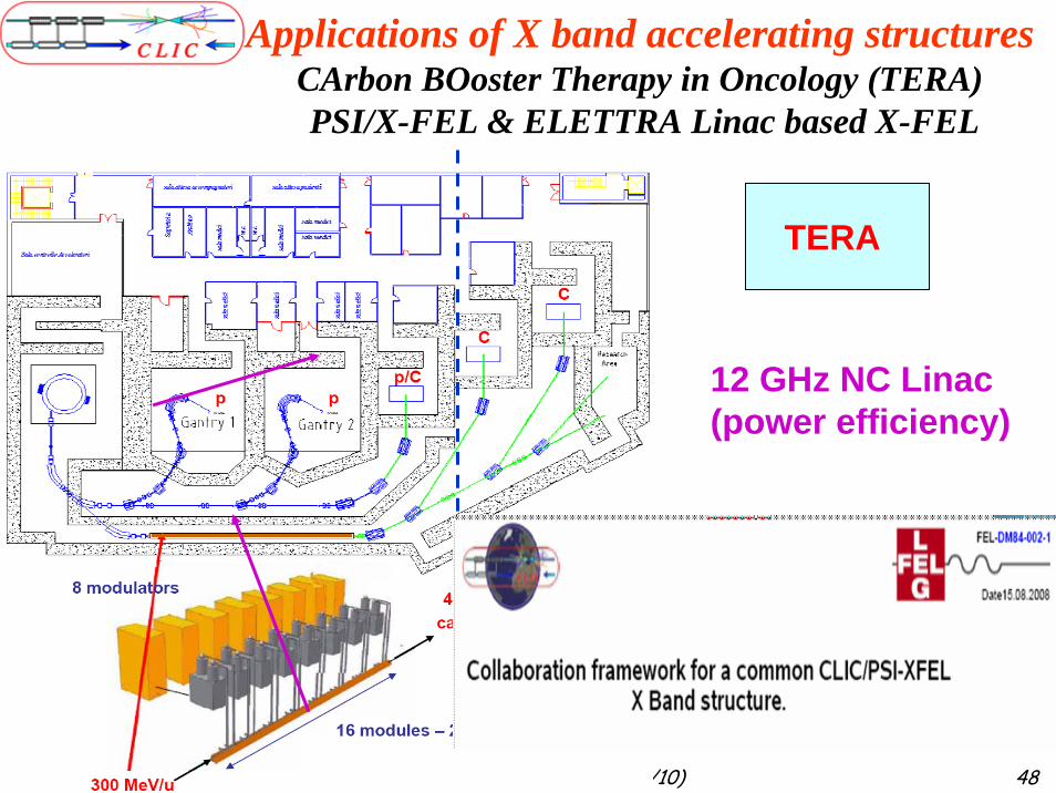
12 GHz NC Linac(power efficiency)
TERA
Applications of X band accelerating structuresCArbon BOoster Therapy in Oncology (TERA)PSI/X-FEL & ELETTRA Linac based X-FEL
Beam emittance preservationBeam Dynamics, alignment and stability
Emittance blow-up from Damping Ring to BDS limited:• in Horizontal to 30% from 500 nrad
• in Vertical to 300% from 5 nrad
Alignment procedure based on:• Actif pre-alignment of beam line components: 15 µm• Beam-based alignment (3 µm) using BPMs with good resolution (100nm)• Alignment of accelerating structures to the beam using wake-monitors • Tuning based on luminosity/beam size measurement with 2% resolution
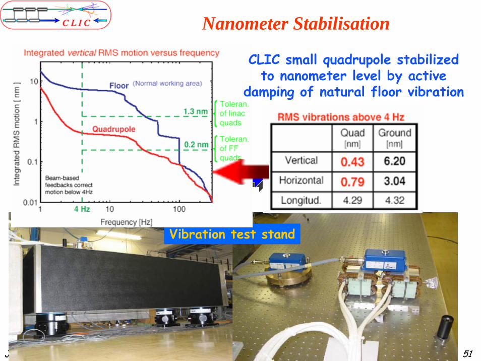
Beam stability by quadrupole stabilisation:0.2nm beam-beam stability@IP• quadrupole passive and active stabilisation• beam feedback (pulse to pulse) and Intrabeam feedback
J.P.Delahaye CLIC @ SAC seminar (03/09/10) 50
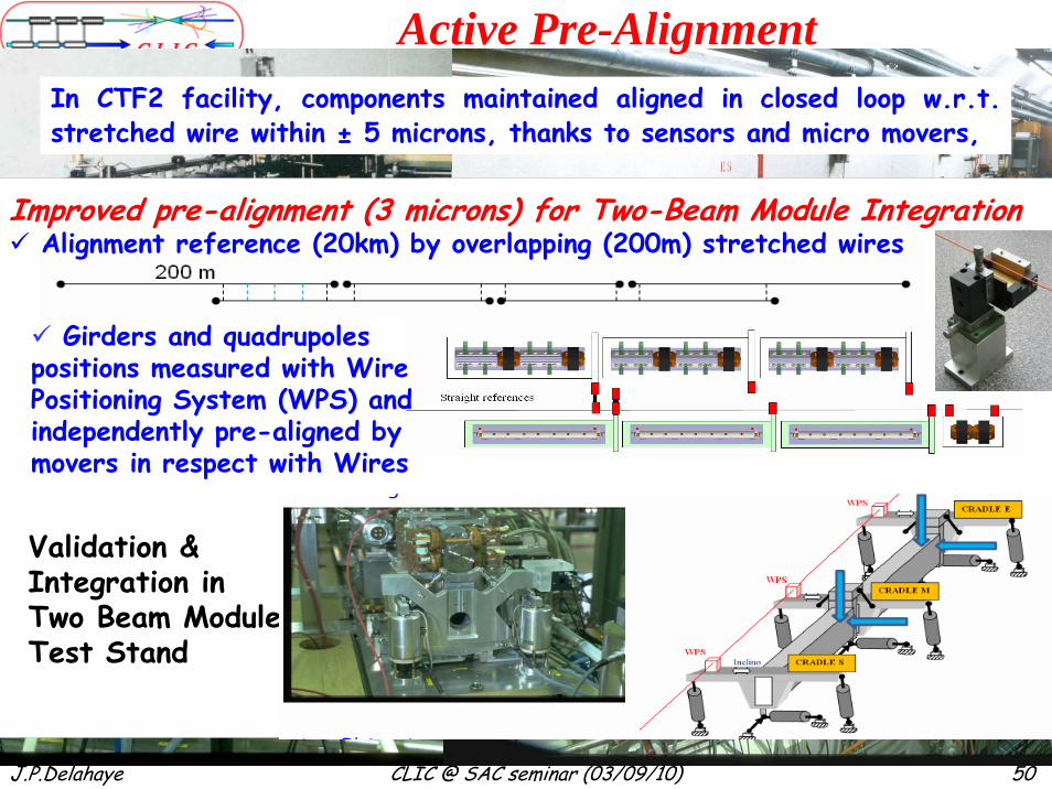
Active Pre-AlignmentIn CTF2 facility, components maintained aligned in closed loop w.r.t. stretched wire within ± 5 microns, thanks to sensors and micro movers,
Improved pre-alignment (3 microns) for Two-Beam Module IntegrationAlignment reference (20km) by overlapping (200m) stretched wires
Validation &Integration inTwo Beam ModuleTest Stand
Girders and quadrupoles positions measured with Wire Positioning System (WPS) and independently pre-aligned by movers in respect with Wires
J.P.Delahaye CLIC @ SAC seminar (03/09/10) 51
Vibration test stand
Nanometer Stabilisation
CLIC small quadrupole stabilizedto nanometer level by active
damping of natural floor vibration
J.P.Delahaye CLIC @ SAC seminar (03/09/10) 52
Test Stands (2 methods) with (future) real quadrupole prototype (400 kg)
Active stabilisation & nano-alignment by
Hexapole:
Passive & Active Isolation
Main linac Quad.
specification
1nm
1nm
Main linac Quad.
specification
[Nm RMS]
[Hz]
10
0.1
100
101
J.P.Delahaye CLIC @ SAC seminar (03/09/10) 53
Nanometer beam sizes in KEK ATF2
Final Focus System Diagnosticb mat-ching Extraction line
Improved performances to address CLIC issues:small(er) beam sizes and high(er) chromaticities
R.M.S. Beam Sizes at Collision in Linear Colliders
ATF2
FFTB
ATF2Ultra-Low
ILC 500 GeV
CLIC500 GeV
CLIC 3 TeV
1
10
100
10 100 1000Horizontal Beam Size (nm)
Vert
ical
Bea
m S
ize
(nm
)
J.P.Delahaye CLIC @ SAC seminar (03/09/10) 54
Machine Detector Interface
Intratrain feedback
kicker
• FD sub-nm jitter tolerance• Supports decoupled from detector & compatible with push-pull mode• Active feedbacks FD stabilization• Intra-train feedback (150 nanosec) Tunnel part
Hybrid permanent magnet QD0
Mechanicalfeedback
Beamfeedback
Feed forward
CLICtarget
J.P.Delahaye CLIC @ SAC seminar (03/09/10) 5555
Detectors in Push-pull mode
Close collaboration with ILC taking advantageof advanced ILC detector conceptsAdapted to CLIC technology: Time stamping (0.5 ns between bunches)