1 The Comparative Analysis of AC-Flux and DC- Flux Resolvers M. Bahari and Z. Nasiri-Gheidari* Department of Electrical Engineering, Sharif University of Technology, Tehran, Iran Mohammad Bahari: [email protected], +98-9057266887 *Corresponding author: Zahra Nasiri-Gheidari ([email protected], +98-21-66164389, +98-9123976830). Abstract—Resolver, as an electromagnetic sensor, is widely used in many industrial applications. It can detect the position of the rotary part of the electric machines precisely. In commercial resolvers, the excitation winding is connected to the high frequency (HF) AC source. The amplitude-modulated voltages induced in the signal windings need to be demodulated in order to calculate the envelope of the output signals and accordingly detect the position. On the other hand, in PM- resolver, signal windings replaced by Hall-effect sensors to measure the DC magnetic flux which is produced by permanent magnets. In this study, the performance of both AC and DC flux resolvers is investigated under different circumstances. All the simulations are done by the time-stepping finite element method (TSFEM). Index Terms— Electromagnetic Sensor, Variable Reluctance (VR) Resolver, Time- stepping Finite Element Method (TSFEM), Hall-effect Sensor, External Magnetic Field I. INTRODUCTION Position sensors play a crucial role in closed-loop motion control systems, especially in inverter-driven electric machines [1]. There are different types of position sensors one of which is a resolver. Resolver is categorized as an electromagnetic position sensor and widely used in different industrial applications [1]-[3]. The main competitors to resolvers are optical encoders. Since optical encoders contain some delicate fragile parts, they cannot tolerate mechanical stresses and cannot be utilized in high-temperature environments. In addition, the performance of optical encoders is highly sensitive to the contamination while resolvers have acceptable performance in those conditions due to their robust structure. The working principle of resolvers is similar to the two-phase Synchronous Generators (2-ph SGs) and the only difference is that the excitation winding of the resolver is supplied by an AC voltage/current source rather than the DC one [3].
Transcript
1
The Comparative Analysis of AC-Flux and DC-
Flux Resolvers
M. Bahari and Z. Nasiri-Gheidari*
Department of Electrical Engineering, Sharif University of Technology, Tehran, Iran
The windings of the traditional brushless resolvers are located in the slots of both the
rotary part and the stationary part. The induced voltage in the secondary coil of a rotary
transformer (RT) fed the excitation winding which is located in the slotted core of the
rotary part. Using RT has advantages such as providing a contactless excitation supply
[4]-[5]. However, it causes phase shift error and also increases the size and the price of
the resolver as well. The proposed structures, nevertheless, use a great volume of copper
and have a complicated manufacturing process. Eventually, variable reluctance (VR)
resolvers are developed with a winding-less solid ferromagnetic rotor [6]-[8]. All of the
aforementioned resolvers supply the excitation winding with AC voltage/current source
[7] and as a result, the AC-excited coils of excitation winding produce AC magnetic field
which flows into the core of the sensor and induced HF voltage in signal windings. In
addition to the radial flux resolvers, axial flux resolvers [9] and linear resolvers [10]-[12]
have been investigated. In [13], a new PM-Resolver with permanent magnets (PMs) in its
structure investigated which shows that the resolver also can work properly with DC
magnetic flux rather than AC magnetic flux. In the aforementioned resolver, PMs
produced DC magnetic flux and due to the position of sinusoidal-form 5-X shape rotor,
the sinusoidal magnetic flux flows through the Hall-effect sensors which are located in
the teeth instead of signal windings to measure the amplitude of flux density. DC flux
resolver has outstanding advantages such as lower cost due to the replacement of signal
windings with cheap Hall-effect sensors and easy calculation of the position. Although
the performance of a resolver with both AC and DC flux is well-proved, no previous
research covers the comparative analysis of those two types of flux in resolvers. As a
result, in this study, the performance of the AC magnetic flux and DC magnetic flux
resolver with different types of excitation is investigated firstly. For the sake of similar
conditions, the excitation winding of DC magnetic flux resolver is connected to the DC
supply and its performance is compared with the commercial AC magnetic flux resolver.
Second, the impact of different constant speeds and different constant accelerations on
the output signals is studied. Eventually, the performance of both AC flux resolver and
DC flux resolver in the presence of an external magnetic field is examined. All the
simulations are done using the time stepping finite element method.
II. STUDIED RESOLVER
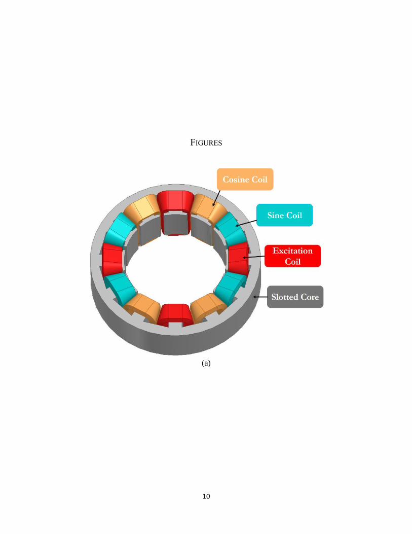
The stator and the coils of the commercial VR resolver, excited with AC supply are
shown in Fig. -a. The conventional stator of the resolver has 12-slots, 4 excitation coils,
and 8 signal coils. The stator, the excitation coils, and Hall-effect sensors of the VR
resolver excited with DC supply are shown in Fig. -b. The stator of the DC excited
resolver has also 12-slots, 4 excitation coils, and 8 Hall-effect sensors (UGN3503). The
rotor of both resolvers is the 5-X shape and shown in Fig. -c. The geometrical dimensions
3
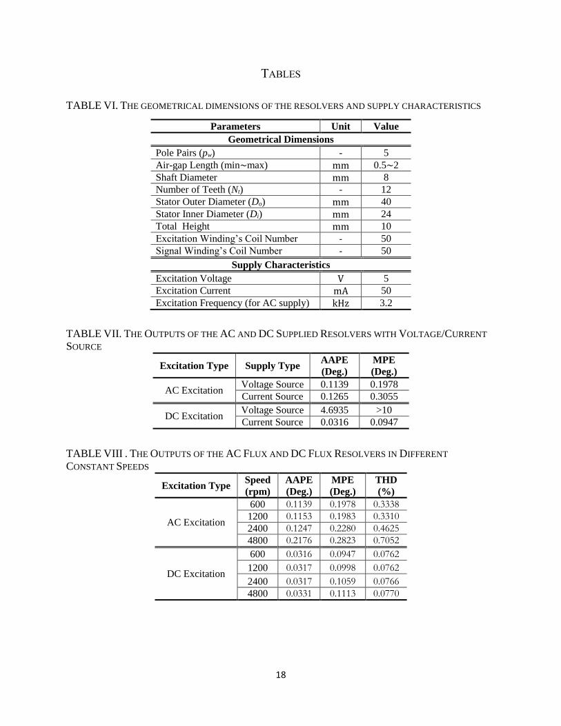
of both resolvers and other characteristics of them are listed in TABLE VI. It is worth
mentioning that the output voltages of the Hall-effect sensor can be obtained as:
(1) s offsetV V V
where Voffset is depended on the amplitude of the voltage supply of the Hall-effect sensor
and ΔV depends on the flux vector of the Hall-effect sensor divided by the area section of
the sensor (�⃗⃗�
𝑨). The output voltages of the hs1, hs2, hs3, and hs4 Hall-effect sensors are
combined to form the output voltage of the sine signal and output voltages of hs1, hs2, hs3,
and hs4 Hall-effect sensors are combined to form the output voltage of the cosine signal,
as below:
(2) 1 2 3 4s s s s sV V V V V
(3) 1 2 3 4c c c c cV V V V V
As can be seen in equation (2) and (3), the offset voltages of the Hall-effect sensors
will be eliminated and the output voltages are only dependent on the magnitude of flux
density of the sensors’ section and not the amplitude of Hall-effect sensor supply. As a
result, even if the amplitude of the sensors’ supply varied the sine signal and cosine
signal as outputs will not be distorted, this proves the robustness of the resolver against
amplitude changes of the sensors’ supply.
III. DIFFERENT SUPPLY TYPE
Supplying the excitation winding with voltage or current source is a challenge for
simulation of resolvers [10], [14]. In this section, to investigate the performance of the
resolvers, both AC flux resolver and DC flux resolver are simulated using TSFEM to
study the influence of the excitation type on the output signals. Fig. -a shows the output
signals of the conventional resolver with the AC voltage source excitation and Fig. -b
shows the output signals of the aforementioned resolver with AC current source. As can
be seen in Fig. , the output signals of AC excited resolver are not affected by the type of
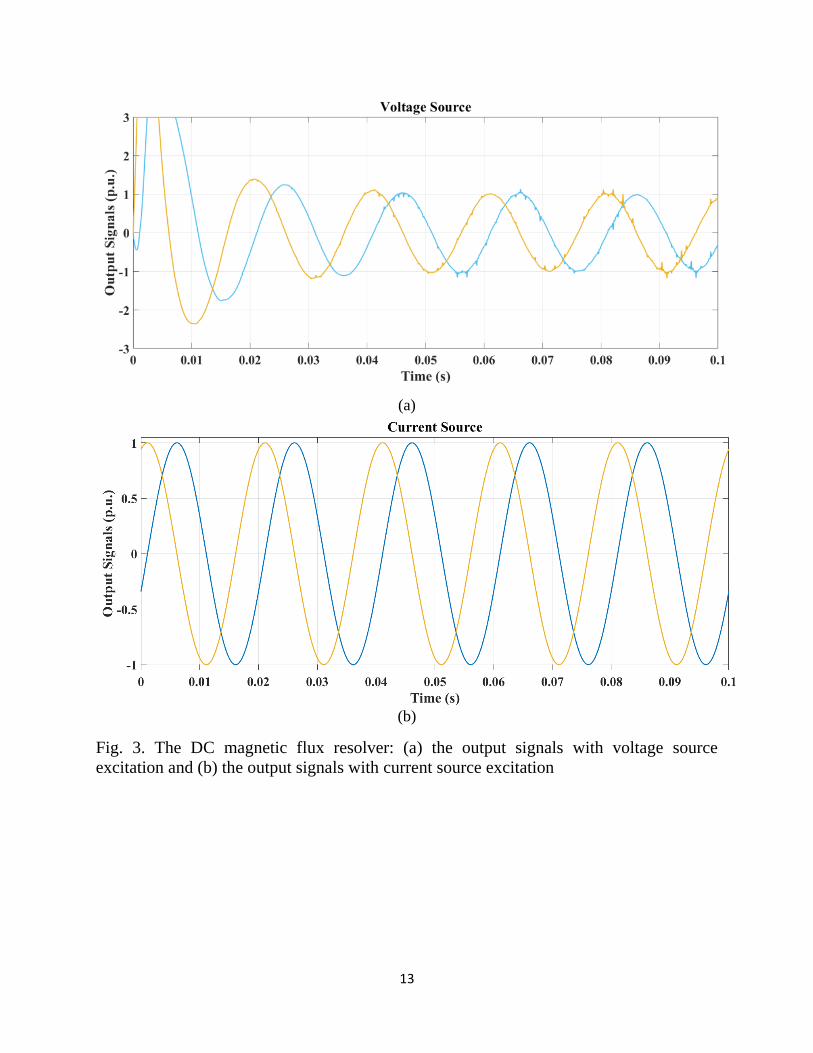
voltage or current source. Fig. -a shows the output signals of the DC magnetic flux
resolver excited with DC voltage source and Fig. -b shows the output signals of the
aforementioned resolver excited with DC current source. Despite the conventional
resolver, the performance of the DC flux resolver is subjected to the supply type. As it
can be seen in Fig. -a, the output signals of voltage excitation suffer from slow dynamic,
which means when the mechanical speed of the rotary part of the resolver changes
rapidly, it takes output signals a long time to (approximately 0.4ms at 600rpm) to get
stable and it is disadvantageous to those applications which need a high-speed dynamic
response. In addition, the accuracy of position detection is not sufficient and the total
harmonic distortion (THD) of the output signals is not acceptable. On the other hand, as it
4
can be seen in Fig. -b, the output signals of the DC flux resolver excited by current source
have desirable sinusoidal form and also get stable very fast. The average of absolute
position error (AAPE) and maximum position error (MPE) of both resolvers excited with
voltage and current source are listed in TABLE VII.
IV. IMPACT OF CONSTANT AND VARIABLE SPEED
Resolver as a position sensor should be able to work properly and calculate the angular
position and the angular speed of electric machines not only in a wide range of speeds but
also in different accelerations. In this section, the performance of AC and DC resolvers
are compared under constant/variable speed conditions. For the sake of fair comparison,
the outputs of both resolvers with AC flux and DC flux are sampled with the same and
constant sampling rate.
a) Constant Speed
For the AC flux resolver, the voltage source with the amplitude of 5V and 3.2 kHz
supplied the excitation winding and for the DC flux resolver, the current source with the
amplitude of 50mA supplied the excitation winding. Simulations are repeated at 600,
1200, 2400, 4800 rpm. the results are presented in Fig. 4 and Fig. 5 for AC and DC
resolvers, respectively. The frequency of the sampling rate is 51.2 kHz applied for both
outputs. As can be seen in Fig. , the quality of the low frequency (LF) envelope of the
induced voltages in the AC flux resolver reduced dramatically when the mechanical
speed of the resolver is increased. The main reason for this is in each period of HF signal,
only two extremum points of the LF envelope are sampled and the position of the rotary
part calculated using the LF envelope in the peak-detection method.
(4) , 16HF Signal AC HF exe HFf n f n
(5) LF Signal AC exef f
In the DC flux resolver, nevertheless, all sampling points building the output signals
of the resolver are used in calculating the position. As a result, the DC flux resolver kept
the quality of its output signals while the mechanical speed of the resolver was
increasing.
(6) LF Signal DC HF Signal ACf f
Consequently, the quality of the output signals in the DC flux resolver is 𝒏𝑯𝑭 times
better than the quality of the output signals in the AC flux resolver. The calculated AAPE
and MPE at different speeds are listed in TABLE VIII.
b) Variable Speed
5
To investigate the performance of both AC- and DC-flux resolvers in variable speeds,
AC flux resolver is simulated in two different angular accelerations. Fig. -a shows the
real speed of the resolver as a reference and calculated the speed of the resolver using
output signals of the AC flux resolver simultaneously when the speed of the rotary part
increases with 628 rad/𝒔𝟐 and 1256 rad/𝒔𝟐. Fig. -b shows the speed error of the
aforementioned resolver. Simulations repeated for DC flux resolver with the same
angular accelerations for the sake of fair comparison. Fig. -a shows the real speed and
also calculated the speed of the DC flux resolver and Fig. -b shows the speed error.
Eventually, the average of absolute speed error (AASE) and the maximum speed error
(MSE) of both resolvers with the same angular accelerations are listed in TABLE IX. It
can be concluded that both AC flux resolver and DC flux resolver operate well when the
rotary part is accelerating. Although the AASE of both resolvers is almost equal, the
MSE of the DC flux resolver is bigger than the AC one. In conclusion, the AC flux
resolver has a better performance in comparison with the DC flux resolver.
V. EFFECT OF EXTERNAL ELECTROMAGNETIC FIELD ON THE PERFORMANCE OF THE
RESOLVER
By distorting the magnetic flux which passes through the Hall-effect sensors,
escalation of the resolver’s position is inevitable. In order to study the influence of
external electromagnetic interference on the performance of both resolvers, two intense
asymmetric electromagnetic fields are simulated in the simulation environment, one of
them is DC field with the amplitude of 2kA/m and the other one is 16 kHz AC field with
the amplitude of 2kA/m. In these simulations, in order to provide similar conditions, both
excitation windings of AC flux and DC flux resolvers are excited with current source
excitation with 50 mA amplitude and 3.2 kHz frequency for AC flux resolver. The
outputs of the resolver such as AAPE and MPE are listed in TABLE X. As it can be seen,
the position error of the AC flux resolver is increased exponentially in the presence of the
external electromagnetic field. Fig. shows distorted induced voltages in signal windings
especially in zero-crossings. Due to the low amplitude of the signal in the zero crossing
section, the rate of the signal to noise decreases and this leads to dramatic position error.
On the other hand, Fig. shows the output signals of the DC flux resolver in the presence
of the external DC electromagnetic field. As it can be seen, the external field distorted
output signals of the DC flux resolver by injecting offset to sine and cosine signal and
consequently, cause increasing the position error of the resolver. The injected offset by
external field can be calculated as:
(7) . .0.022p u
UP LPV V V
6
On the other hand, the DC electromagnetic field has a little effect on the performance
of the AC flux resolver, and also the performance of the DC flux resolver in the presence
of the AC electromagnetic field is acceptable.
VI. CONCLUSION
In this paper, a comparative analysis between AC flux and DC flux resolvers was
done. A variable reluctance resolver with 12-slot stator and 5-X shape rotor was taken as
a study case. The position errors of both resolvers in normal conditions examined when
the current source and voltage source supplied the excitation winding and among
different scenarios, DC flux resolver with current source had the lowest AAPE and MPE.
In order to study the accuracy in different conditions, both AC flux and DC flux resolvers
were simulated in a wide range of speeds and accelerations. It was shown that the quality
of output signals and their envelope in AC flux resolver reduced dramatically when the
angular speed of the rotor increased. On the other hand, the DC flux resolver kept its
acceptable accuracy even at high speed. Although DC flux resolver has proved its
practicality in high-speed applications, the performance of both resolvers was close to
each other in different angular accelerations. At last, the output signals of both resolvers
examined in the presence of external distortions. Simulation results indicated that AC
flux resolvers almost kept their accuracy when an external DC magnetic field exists;
however, an external AC magnetic field distorted their output signals. On the other side,
DC flux resolver has shown acceptable performance against an external AC magnetic
field while its accuracy highly affected by an external DC magnetic field. To sum up, DC
flux resolvers have a great number of advantages such as lower cost, easy position
calculation, ability to measure the position in a wide range of speed, and robust
performance against AC distortions in comparison with commercial AC flux resolvers
which have complex winding configuration and as a result, they deserve more attention.
REFERENCES
[1] Ge X., Zhu Z. Q., Ren R., et al. “A Novel Variable Reluctance Resolver for HEV/EV Applications”, IEEE Trans. Ind. Appl., 52 (4), pp. 2872 - 2880, (2016)
[2] Tootoonchian F., “Design, Performance, and Testing of a Brushless Axial Flux Resolver without Rotor Windings”, IEEE Sensors Journal, 16 (20), pp. 7464-7471, (2016)
[3] Murray A., Hare B. and Hirao A., "Resolver Position Sensing System with Integrated Fault Detection for Automotive Applications," Sensors, 2002 IEEE, Orlando, FL, USA, 2002, pp. 864-869 vol.2.
7
[4] Sun L., "Analysis and Improvement on The Structure of Variable Reluctance Resolvers," IEEE Transactions on Magnetics, 44 (8), pp. 2002-2008, (2008)
[5] Mohammad-Yari M., Safari M., Alipour-Sarabi R., et al., “Optimal Winding Selection for Wound-Rotor Resolvers”, Scientia Iranica, DOI: 10.24200/sci.2019.52439.2764, early access
[6] Ge X. and Zhu Z. Q., "A Novel Design of Rotor Contour for Variable Reluctance Resolver by Injecting Auxiliary Air-Gap Permeance Harmonics," in IEEE Transactions on Energy Conversion, 31 (1), pp. 345-353, (2016).
[7] Sun L., "Analysis and Improvement on the Structure of Variable Reluctance Resolvers," in IEEE Transactions on Magnetics, 44(8), pp. 2002-2008, (2008).
[8] Ge X., Zhu Z. Q., R. Ren and J. T. Chen, "A Novel Variable Reluctance Resolver with Nonoverlapping Tooth–Coil Windings," IEEE Transactions on Energy Conversion, 30 (2), pp. 784-794, (2015)
[9] Alipour-Sarabi R., Nasiri-Gheidari Z. and Oraee H., "Development of a 3-D Magnetic Equivalent Circuit Model for Axial Flux Machines," IEEE Transactions on Industrial Electronics, early access.
[10] Daniar A., Nasiri-Gheidari Z. and Tootoonchian F., "Performance Analysis of Linear Variable Reluctance Resolvers Based on an Improved Winding Function Approach," IEEE Transactions on Energy Conversion, 33 (3), pp. 1422-1430, (2018)
[11] Bahari M. and Nasiri-Gheidari Z., "Longitudinal End Effect in a Variable Area Linear Resolver and its Compensating Methods," Electrical Engineering (ICEE), Iranian Conference on, Mashhad, 2018, pp. 1316-1321.
[12] Bahari M., Alipour-Sarabi R., Nasiri-Gheidari Z. et al., "Proposal of Winding Function Model for Geometrical Optimization of Linear Sinusoidal Area Resolvers," IEEE Sensors Journal, 19(14), pp. 5506-5513, (2019)
[13] Bahari M., Davoodi A., Saneie H., et al., "A New Variable Reluctance PM-Resolver," IEEE Sensors Journal, 20(1), pp. 135-142, (2020)
[14] Wang K. and Wu Z., "Hardware-Based Synchronous Envelope Detection Strategy for Resolver Supplied with External Excitation Generator," IEEE Access, 7, pp. 20801-20810, (2019)
8
Mohammad Bahari received the B.Sc. degree from Semnan University, Semnan, Iran, in 2015,
and the M.Sc. degree from the Sharif University of Technology, Tehran, Iran, in 2019, all in
electrical engineering. His research interests include design, modeling, and control of electrical
machines, and finite-element analysis of electromagnetic devices.
Zahra Nasiri-Gheidari received the B.Sc. degree from the Iran University of Sciences and
Technology, Tehran, Iran, in 2004, and the M.S. and Ph.D. degrees from University of Tehran,
Tehran, in 2006 and 2012, respectively, all in electrical engineering. She is currently an
Associate Professor with the Department of Electrical Engineering, Sharif University of
Technology. Her research interests include design, optimization, and performance analysis of
electrical machines and electromagnetic sensors.
Fig. 1. The conventional and DC supplied resolver: (a) the stator of the conventional
resolver, (b) the stator of the DC supplied resolver, and (c) the rotor of both resolvers
Fig. 2. The commercial resolver with AC magnetic flux: (a) the output signals with
voltage source excitation and (b) the output signals with current source excitation
Fig. 3. The DC magnetic flux resolver: (a) the output signals with voltage source
excitation and (b) the output signals with current source excitation
Fig. 4. Induced voltages of AC flux resolver in different speeds
Fig. 5. Output Signals of DC flux resolver in different speeds
Fig. 6. Performance of the AC flux resolver with two different angular accelerations: (a)
real speed of the resolver and calculated speed by output signals and (b) Speed error
Fig. 7. Performance of the DC flux resolver with two different angular accelerations: (a)
real speed of the resolver and calculated speed by output signals and (b) Speed error
9
Fig. 8. The effect of an AC external electromagnetic field on the induced voltages of the
AC flux resolver
Fig. 9. The effect of a DC external electromagnetic field on the DC flux resolver
TABLE I. THE GEOMETRICAL DIMENSIONS OF THE RESOLVERS AND SUPPLY CHARACTERISTICS
TABLE II. THE OUTPUTS OF THE AC AND DC SUPPLIED RESOLVERS WITH VOLTAGE/CURRENT
SOURCE
TABLE III . THE OUTPUTS OF THE AC FLUX AND DC FLUX RESOLVERS IN DIFFERENT CONSTANT
SPEEDS
TABLE IV. THE OUTPUTS OF BOTH AC AND DC FLUX RESOLVERS WITH DIFFERENT ANGULAR
ACCELERATIONS
TABLE V. THE PERFORMANCE OF THE RESOLVERS IN THE PRESENCE OF EXTERNAL
ELECTROMAGNETIC FIELDS
10
FIGURES
(a)
11
(b)
(c)
Fig. 1. The conventional and DC supplied resolver: (a) the stator of the conventional
resolver, (b) the stator of the DC supplied resolver, and (c) the rotor of both resolvers
12
(a)
(b)
Fig. 2. The commercial resolver with AC magnetic flux: (a) the output signals with
voltage source excitation and (b) the output signals with current source excitation
13
(a)
(b)
Fig. 3. The DC magnetic flux resolver: (a) the output signals with voltage source
excitation and (b) the output signals with current source excitation
14
Fig. 4. Induced voltages of AC flux resolver in different speeds
Fig. 5. Output Signals of DC flux resolver in different speeds
15
(a)
(b)
Fig. 6. Performance of the AC flux resolver with two different angular accelerations: (a)
real speed of the resolver and calculated speed by output signals and (b) Speed error
16
(a)
(b)
Fig. 7. Performance of the DC flux resolver with two different angular accelerations: (a)
real speed of the resolver and calculated speed by output signals and (b) Speed error
17
Fig. 8. The effect of an AC external electromagnetic field on the induced voltages of the
AC flux resolver
Fig. 9. The effect of a DC external electromagnetic field on the DC flux resolver
18
TABLES
TABLE VI. THE GEOMETRICAL DIMENSIONS OF THE RESOLVERS AND SUPPLY CHARACTERISTICS
Parameters Unit Value
Geometrical Dimensions
Pole Pairs (pw) - 5
Air-gap Length (min~max) mm 0.5~2
Shaft Diameter mm 8
Number of Teeth (Nt) - 12
Stator Outer Diameter (Do) mm 40
Stator Inner Diameter (Di) mm 24
Total Height mm 10
Excitation Winding’s Coil Number - 50
Signal Winding’s Coil Number - 50
Supply Characteristics
Excitation Voltage V 5
Excitation Current mA 50
Excitation Frequency (for AC supply) kHz 3.2
TABLE VII. THE OUTPUTS OF THE AC AND DC SUPPLIED RESOLVERS WITH VOLTAGE/CURRENT
SOURCE
Excitation Type Supply Type AAPE
(Deg.)
MPE
(Deg.)
AC Excitation Voltage Source 0.1139 0.1978
Current Source 0.1265 0.3055
DC Excitation Voltage Source 4.6935 >10
Current Source 0.0316 0.0947
TABLE VIII . THE OUTPUTS OF THE AC FLUX AND DC FLUX RESOLVERS IN DIFFERENT
CONSTANT SPEEDS
Excitation Type Speed
(rpm)
AAPE
(Deg.)
MPE
(Deg.)
THD
(%)
AC Excitation
600 0.1139 0.1978 0.3338
1200 0.1153 0.1983 0.3310
2400 0.1247 0.2280 0.4625
4800 0.2176 0.2823 0.7052
DC Excitation
600 0.0316 0.0947 0.0762
1200 0.0317 0.0998 0.0762
2400 0.0317 0.1059 0.0766
4800 0.0331 0.1113 0.0770
19
TABLE IX. THE OUTPUTS OF BOTH AC AND DC FLUX RESOLVERS WITH DIFFERENT ANGULAR
ACCELERATIONS
Excitation
Type
Angular Acceleration
(rad/𝒔𝟐)
AASE
(rpm)
MSE
(rpm)
AC
Excitation
628 2.56 12.91
1256 2.54 12.33
DC
Excitation
628 2.61 26.92
1256 2.62 23.01
TABLE X. THE PERFORMANCE OF THE RESOLVERS IN THE PRESENCE OF EXTERNAL