NASA Technical Paper 3534 The Corrosion Protection of 2219-T87 Aluminum by Organic and Inorganic Zinc-Rich Primers M.D. Danford, D.W. Walsh, and M.J. Mendrek February 1995 https://ntrs.nasa.gov/search.jsp?R=19960020524 2018-04-17T12:41:59+00:00Z
Transcript
NASA Technical Paper 3534
The Corrosion Protection of 2219-T87 Aluminum by Organic and Inorganic Zinc-Rich Primers M.D. Danford, D.W. Walsh, and M.J. Mendrek
The Corrosion Protection of 2219-T87 Aluminum by Organic and Inorganic Zinc-Rich Primers M.D. Danford and M.J. Mendrek Marshall Space Flight Center MSFC, Alabama
D.W. Walsh California Polytechnic State University San Luis Obispo, California
National Aeronautics and Space Administration Marshall Space Flight Center 9 MSFC, Alabama 35812
February 1995
TABLE OF CONTENTS
Page
INTRODUCTION ......................................................................................................................... EXPERIMENTAL PROCEDURE ................................................................................................ RESULTS AND DISCUSSION ....................................................................................................
Organic primer ................................................................................................................... Inorganic Primer ................................................................................................................ Galvanic Current Measurements ........................................................................................
Equivalent circuit model used for analysis of EIS data ................................................. Charge transfer resistance. organic primer .................................................................... Pore resistance. organic primer ...................................................................................... ZCORR. organic primer ..................................................................................................... Coating capacitance. organic primer ............................................................................. Charge transfer capacitance. organic primer ................................................................. Charge transfer resistance. inorganic primer ................................................................. Pore resistance. inorganic primer .................................................................................. ZCORR. inorganic primer .................................................................................................
Organic (top) and inorganic zinc-rich primer coated 22 19-T87 after 2 1 days exposure to 3.5-percent Na-Cl ....................................................................................... Coating capacitance. inorganic primer ..........................................................................
Charge transfer capacitance. inorganic primer .............................................................. Comparison of pore resistances for organic and inorganic primers ..............................
Comparison of ZCORR curves for organic and inorganic primers ...................................
Page
5
6
6
7
9
10
11
11
12
12
V
TECHNICAL, PAPER
THE: CORROSION PROTECTION OF 2219-T87 ALUMINUM BY ORGANIC AND INORGANIC ZINC-RICH PRIMERS
INTRODUCTION
The space transportation system (STS) solid rocket boosters (SRB’s) are reusable solid motors that provide the major source of thrust during the first 2 min of launch. After separation and parachute deployment, the motors splash down into the Atlantic Ocean and are recovered. Recovery and towback operations usually take 24 to 36 h. During this period, the aggressive seawater environment causes severe corrosion of exposed bare metal hardware. The SRB aft skirt experiences the worst damage because it is completely submerged during the first several hours after splashdown, when the boosters are in the vertical position. The aft skirt remains partially submerged during towback. Aggravating aft skirt corrosion is a galvanic effect driven by coupling to the thrust vector control (TVC) system (comprised primarily of stainless steel and titanium) and the redesigned solid rocket motor nozzle (which contains carbon).
The aft skirt is constructed from aluminum alloy 2219-T87. This high-strength aluminum alloy is age hardened primarily by precipitation of copper aluminide. (CU-AZ~), which is significantly more noble than the aluminum matrix, making the alloy susceptible to pitting corrosion by a microscopic galvanic mechanism. This dual galvanic effect makes the aft skirt extremely susceptible to pitting corrosion. Areas behind the TVC system are severely affected.
The current protection system for the aft skirt includes a chemical conversion coating, followed by a chromate inhibited epoxy primer and an epoxy topcoat. This system should provide excellent pro- tection, particularly if the coating is not damaged. However, some damage does occur and is believed to be the result, in part, of shards of carbon cloth phenolic from the nozzle penetrating the coating. These tiny needles not only compromise the coating system, but result in contact of a very noble material with the aluminum structure. When the booster is in the vertical position, the aft skirt is under approximately 100 ft of seawater, at three atmospheres pressure. This pressure drives seawater into defects in the coat- ing, and the available chromate is apparently insufficient to prevent pitting attack.
Corrective action to reduce the pitting in the aft skirt has included the use of flame-sprayed zinc, attached zinc anodes, and diver-installed zinc anodes. These efforts have met with limited success because the area of available zinc is insufficient to provide complete protection, and the zinc currently in use is not ideally located to provide protection where it is needed the most, Le., behind the TVC system.
These problems may be resolved if the proposal to apply zinc-rich primer to the interior of the aft skirt is successful. The zinc in the primer protects by acting as a sacrificial anode rather than by chro- mate inhibition. If the zinc-rich primer is compromised, as long as the affected area is not too large, this sacrificial protection should be adequate to protect the exposed aluminum. The problem is that zinc-rich primers are intended primarily for use on steels, where the difference in electrochemical potential is on the order of 500 mV. The electrochemical potential of aluminum is roughly midway between that of zinc and steel. Whether the zinc in the zinc-rich primer will provide sufficient galvanic protection to 2219 aluminum is the question that was addressed by this work. To that end, a comparison was made between the organic zinc-rich primer currently used on SRB steel hardware and an inorganic zinc-rich primer
which had demonstrated success in the Kennedy Space Center (KSC) seacoast environment. The differ- ence between the two types of coating lies in the binder. The organic primer has an epoxy binder, while the inorganic primer has an ethyl silicate binder. The type of binder has a significant effect on primer performance. This effect has been investigated on steel,l-3 but not on aluminum. Electrochemical com- parison of the inorganic primer (heronTM) to the organic primer (Rust-OleumTM) currently used on the SRB should provide a means for determining which primer is likely to provide the best galvanic protection for 2219-T87 aluminum.
EXPERIMENTAL PROCEDURE
Flat plates, 10.2 by 15.2 cm (4 by 6 in), of 2219-T87 aluminum alloy were grit blasted and cleaned with alcohol and acetone. Two plates were coated with approximately 0.08 mm (3 mils) of inorganic zinc-rich primer 21-9, manufactured by Ameron Co., and two more were coated with organic zinc-rich primer manufactured by the Rust-Oleum Corp. One each of the coated plates was clamped into a flat corrosion cell manufactured by EG&G-PARC and exposed to 3.5-percent sodium chloride (Na-Cl), and corrosion data were obtained over a period of 21 days. Silver/silver chloride reference elec- trodes were used in all cases.
Both electrochemical impedance spectroscopy (EIS), an alternating current method, and the polarization resistance (PR) technique, a direct current technique, were employed in this investigation. The EG&G-PAEC model 378 ac impedance system was used for all corrosion measurements. For the EIS measurements, data were taken in three frequency ranges. The first two ranges, beginning at 0.001 and 0.1 Hz, respectively, were obtained using the fast Fourier transform technique. The data in the third range, 6.28 to 40,000 Hz, were collected using the lock-in amplifier technique. The sequencing was per- formed using the autoexecute procedure, with all data merged to a single set for each run. After collec- tion, these data were processed and analyzed by computer using the model of figure 1. The same com- puter also controlled the equipment. The development and selection of the model of figure 1 has been discussed previ~usly.~ Values for each of the circuit components in figure 1 were treated as parameters in the nonlinear ORGLSS least squares program, which automatically adjusted these parameters to obtain a best fit to the observed Bode magnitude data (log impedance versus log w , where o = 27r x frequency).
Data for the PR technique were collected using the same instrumentation with the EG&G-PARC model 352 software, which was developed especially for dc measurements. Instrumentation developed by EG&G-PARC automatically corrected the data for IR drop during the scan. The potential applied to the specimen during the scan was varied from -20 to +20 mV on either side of the corrosion potential ECORR, and the data points (current and potential) were recorded in 1/4-mV increments. The PR data were analyzed using the program POLCURR.6 The theory for the PR technique has been described previ~usly.~ In this work, all values of the corrosion current (ZCORR) were obtained using the PR tech- nique.
RESULTS AND DISCUSSION
Organic Primer
EIS measurements showed an impedance that gradually increased over the period of the meas- urements. This result is just the opposite of what is normally observed (i.e., the impedance decreases
2
with time). The charge transfer resistance (&)-time curve is given in figure 2, showing a continually increasing value of Rt. The same trend is observed in figure 3 for the pore resistance (Rp)-time curve, which changes from 0.6 kilohms (kQ) at the onset to a value of 7.4 ksz after the 21-day exposure. The average value of Rp was 4.0 kQ. The corrosion current (Icom)-titlle curve in figure 4 shows a con- tinually decreasing value of I C O ~ during the period of measurement. The average value of I C O ~ was 0.35 pAIcm2, which corresponds to an average corrosion rate of 0.2 mils per year (mpy), assuming that only the zinc is corroding. The coating capacitance C&ne and double layer capacitance Cd-time curves are shown in figures 5 and 6, respectively, showing sharp drops in capacitance during the 5 days of exposure, with slowly decreasing values thereafter. This trend would also contribute to a steady increase in impedance, as would the increasing values of the resistance.
Capacitances may be expressed by the following equation:
Here, K is the dielectric constant, A is the effective area of the condenser, and S is the thickness of the dielectric layer. Assuming that A and S do not greatly change, the decrease in capacitance could be explained by the continual replacement of the initial dielectric medium with high dielectric constant, such as water, with a medium with lower dielectric constant, such as zinc hydroxide in this case, which is consistent with a gradual decrease in porosity.
Inorganic Primer
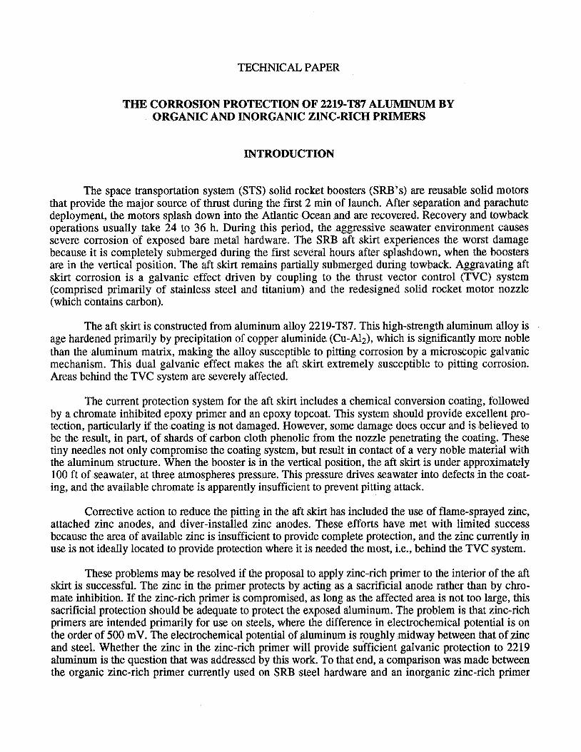
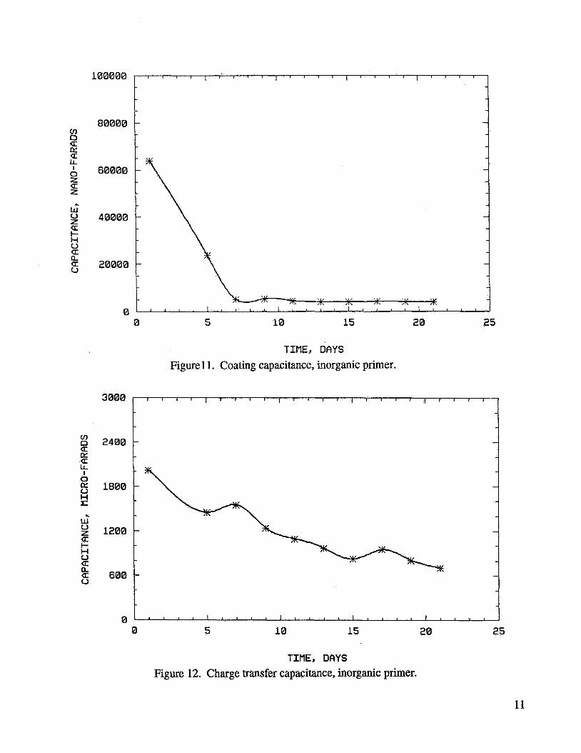
Trends in the results were the same as those for the organic primer, except that measured impedances were much lower. The &-time curve is shown in figure 7 and the Rp-time curve in figure 8. - The R, values began at only 1.2 Q and ended at 132.3 Q. these values are much smaller than the corresponding values of 0.6 kSZ and 7.39 kQ for the organic primer, indicating a very high porosity and associated diffusion in the inorganic primer. The ZcoRR-time curve is shown in’figure 9, dropping from 35.6 pA/cm2 to a value of 5.8 pA/cm2 in 21 days. The average value of ZCORR is 9.0 pA/cm2. This is much higher than 0.35 pNcrn2 obtained for the organic primer. Both values are primarily the result of zinc corrosion. The large values in the inorganic primer are probably the result of the diffusion of the medium to areas surrounding the 1-cm2 area actually exposed to the medium, with areas much larger than 1 cm2 contributing to the corrosion current. Evidence on the coated plate indicated that diffusion of the medium through the primer-coated layer extended to a radius of approximately 4.5 cm (1.75 in) beyond the 1-cm2 exposed area. Figure 10, which compares the organic and inorganic primer-coated panels after 21 days of exposure, illustrates this effect. The C,-time and &-time curves are shown in figures 11 and 12, respectively, showing the same trends as those for the organic primer, with the same implications regarding effects on the total impedance. Comparison of the R,-time curves for the organic and inorganic primers is made in figure 13. This figure illustrates the much greater porosity of the inorganic primer. A similar comparison for the IcoRR-time curves is made in figure 14, showing the much higher values of ZCORR in the case of the inorganic primer, a result of the high diffusion rate of the medium through this porous primer.
Galvanic Current Measurements
Galvanic current measurements were made with a flat cell especially designed for such purposes by EG&G-PARC. Aluminum alloy 2219-T87 plates coated with each primer were clamped into one end
3
of the cell, with a bare, grit-blasted aluminum plate at the other end. The areas exposed to the medium were 1 cm2 for both plates. Current measurements were made individually on each primer-coated plate. Currents were measured using the EG&G-PARC model 352 software over a 24-h period, and the mean current for each primer was calculated. The mean current for the plate coated with organic primer was 37.9 pA/cm*, while that for a plate similarly coated with inorganic primer was 23.7 pNcm2. The lower value for the inorganic primer might be due to a surface more sparsely coated with zinc, as evidenced by the high porosity. However, both currents were relatively high, with the zinc-rich primer acting as the anode. The potentials displayed by both primers were very close to that reported for pure zinc, namely -1,050 mV (SCE)? although that for the organic primer was a little more positive. This may be a result of the lower porosity displayed by the organic primer. At the end of the 24-h galvanic test, there was some evidence of corrosion on the bare aluminum plates for both the organic and inorganic primers, indicating that corrosion protection was not complete.
CONCLUSIONSDZECOMMENDATIONS
This work has demonstrated the feasibility of using zinc-rich primers for galvanic protection of the SRB aft skirt. Electrochemical galvanic corrosion testing of the zinc-rich primers coupled to 2219- T87 aluminum showed that the zinc was anodic to the aluminum and that substantial protective currents were generated. Complete protection of the aluminum was not realized, but may be achieved by using a higher anode-to-cathode ratio.
EIS data have further demonstrated that the inorganic zinc-rich primer will provide superior protection, due to the high porosity and resulting high corrosion current generated during the first several days of immersion. The corrosion current during the first 3 days, which represents the most critical period for aft skirt protection, is between 1 and 2 orders of magnitude higher for the inorganic zinc-rich primer. The higher porosity undoubtedly contributes to a higher apparent anode-to-cathode ratio, which is preferred for cathodic protection.
Based on these results, it is recommended that additional testing be conducted to verify the effi- cacy of using zinc-rich primers in the aft skirt. This work should simulate actual aft skirt conditions, including coupling of coated aluminum to stainless steel and carbon cloth phenolic. A chromated-epoxy control should be included to demonstrate that the cathodic protection provided by the zinc-rich primer is superior to the chromate-inhibited protection provided by the epoxy primer.
4
CS
SUBUNIT 1 +
l t -
Rs F4 I *
cdl
SUBUNIT 2
Cf
UNIT 2 UNIT 1
COATING-SOLUTION UNIT METAL-C OAT1 NG UNIT
Cs SOLUTION CAPACITANCE
Rs SOLUTION RESISTANCE
C f FARADAIC CAPACITANCE (COATING/SOLUTION)
Rf FARADAIC RESISTANCE
C, COATING CAPACITANCE
Rp COATING RESISTANCE
Rt CHARGE TRANSFER RESISTANCE
Cdl METAUCOATING INTERFACE CAPACITANCE
Figure 1. Equivalent circuit model used for analysis of EIS data.
5
100
80
60
40
20
0
10
8
6
4
2
0
TIME, DAYS
TIME, DAYS Figure 3. Pore resistance, organic primer.
6
I= u a v) \ U 1
t- z w Ix (r 3 0
v) 0 a Ix a LL
0 z U z
w 0 2 t- H 0
I
4
a
a a a u
2
1.5
1
0.5
0
1000
800
600
400
0 5 10 15
TIME, DAYS
Figure 4. ICORR, organic primer.
20 25
TIME, DAYS
Figure 5. Coating capacitance, organic primer.
7
1000
800
600
400
200
0 0 5 10 15 20 25
TIME, DAYS Figure 6. Charge transfer capacitance, organic primer.
TIME, DflYS
Figure 7. Charge transfer resistance, inorganic primer.
8
0.2
0.15
0.1
0.05
0 0 5 10 15 20 25
TIME, DAYS
Figure 8. Pore resistance, inorganic primer.
0 5 10 15 20 25
TIME, DAYS Figure 9. ZCORR, inorganic primer.
9
Figure 10. Organic (top) and inorganic zinc-rich primer coated 2219-T87 after 21 days exposure to 3.5-percent Na-C1.
Figure 12. Charge transfer capacitance, inorganic primer.
11
0 5 10 15 20 25
TIME, DAYS Figure 13. Comparison of pore resistances for organic and inorganic primers.
40
30
20
10
0 0 5 10 15 20 25
ORG. INORG .
.. -x- - ORG. + INORG.
TIME, DAYS Figure 14. Comparison of I c o R R curves for organic and inorganic primers.
12
REFERENCES
1. Feliu, S., Barajas, R., Bastidas, J.M., and Morcillo, M.: “Mechanism of Cathodic Protection of Zinc-Rich Paints by Electrochemical Impedance Spectroscopy. I. Galvanic Stage.” J. Coatings Technology, vol. 61, 1989, p. 63.
Areas, RA., Gervasi, C.A., Di Sarli, A., Real, S.G., and Vilche, J.R.: “Zinc-Rich Paints on Steels in Artificial Seawater by Electrochemical Impedance Spectroscopy.” Corrosion, vol. 48, 1992, p. 379.
2.
3. Frydrych, D. J., Farrington, G.C., and Townsend, H.E.: “Electrochemical Impedance Spectroscopy of Zinc-Rich Organic Coatings on Steel.” In Corrosion Protection by Organic Coatings, Proceedings of the Electrochemical Society, Kendig, M. and Leidheiser, H., editors, vol. 87-2, Pennington, NJ, 1987.
4. Danford, M.D.: NASA Technical Memorandum 100402, June 1990.
5. Busing, W.R., and Levy, H.A.: “General Nonlinear Least Squares Program ORGLS.” Oak Ridge National Laboratory, 1958.
6. Gerchakov, S.M., Udey, L.R., and Mansfield, F.: “An Improved Method for Analysis of Polarization Resistance Data.” Corrosion, vol. 37, 198 1 ;p. 696.
7. Danford, M.D., and Higgins, R.H.: NASA Technical Paper 2459, April 1985.
8. Kuster, C.A., and Cooper, G.H.: “Electromotive Series for Aerospace Metals and Alloys.” Rocketdyne Final Report MFTR 7-177-100, January 1967.
* U.S. GOVERNMENT PR I NTl NG OF Fl CE 1995-633-1 09/20008 13
REPORT DOCUMENTATION PAGE Form Approved O M 8 NO. 0704-0188
~~
Duolic reoortinq aurden for this cOllectlOn of information is estimated to averaqe? hour 3er resw>s& includtng the t m e for reviewi~n~tructions, searchtng existing data wurc 3arhermq dnd maintaining the data needed. and comoleting and reviewing :he iollection of information Send comments r arding this burden estimate or any other aspect of t :ollecrron of Inforrnat~On. mludmg SuggeStrons for reducing this burden to Nashingron Headsuarters Services. Dtrenoratf% Information Operations and Reports, 1215 Jeffwr Davis Htqh#vav. Suite 1204. Arlington. J A 222024302. and to the Office gf Management and Budget, Paperwork Reduction Project(0704-0188). Washington. DC 20503.
1. AGENCY USE ONLY (Leave blank) 3. REPORT TYPE AND DATES COVERED February 1995 Technical Pauer
6. TITLE AND SUBTITLE
The Corrosion Protection of 2219-T87 Aluminum by Organic and Inorganic Zinc-Rich Primers
6. AUTHOR(5)
M.D. Danford, D.W. Walsh,* and M.J. Mendrek
7. PERFORMING ORGANIZATION NAME(S) AND ADDRESS(ES)
George C. Marshall Space Flight Center Marshall Space Flight Center, Alabama 358 12
3. SPONSORING / MONITORING AGENCY NAME(S) AND AODRESS(ES)
National Aeronautics and Space Administration Washington, DC 20546
5. FUNDING NUMBERS
6. PERFORMING ORGANIZATION REPORT NUMBER
M-771
10. SPONSORING /MONITORING AGENCY REPORT NUMBER
NASA TP-3534
11. SUPPLEMENTARY NOTES
Prepared by Materials and Processes Laboratory, Science and Engineering Directorate. *California Polytechnic State University.
Subject Category 26 Unclassif ied-Unlimited
The behavior of zinc-rich primer-coated 2219-T87 aluminum in a 3.5-percent Na-C1 was investigated using electrochemical techniques. The alternating current (ac) method of electro: chemical impedance spectroscopy (EIS), in the frequency range of 0.001 to 40,000 Hz, and the direcl current (dc) method of polarization resistance (PR) were used to evaluate the characteristics of an organic, epoxy zinc-rich primer and an inorganic, ethyl silicate zinc-rich primer. A dc electrochemi- cal galvanic corrosion test was also used to determine the corrosion current of each zinc-rich primer anode coupled to a 2219-T87 aluminum cathode. Duration of the EISPR and galvanic testing was 21 days and 24 h, respectively. The galvanic test results demonstrated a very high galvanic current between the aluminum cathode and both zinc-rich primer anodes (37.9 w c m 2 and 23.7 @cm2 for the organic and inorganic primers, respectively). The PR results demonstrated a much higher corro- sion rate of the zinc in the inorganic primer than in the organic primer, due primarily to the higher porosity in the former. Based on this investigation, the inorganic zinc-rich primer appears to provide superior galvanic protection and is recommended for additional study for application in the solid rocket booster aft skirt.
coated metals, primer-coated 2219 Al, organic and inorganic zinc-rich primer