THE CV35—A VELOCITY-MODULATION REFLECTION OSCILLATOR FOR WAVELENGTHS OF ABOUT 10 CM* By A. F. PEARCE, Ph.D.,t and B. J. MAYO, B.Sc.| {The paper was first received 3rd May, and in revised form 1st July, 1946.) ABSTRACT The paper describes a stable tunable oscillator, made in three models covering the waveband from about 8 to 11 cm, which was designed in 1940-41 as a beating oscillator for superheterodyne receivers, and has since been in manufacture and operational use. The construction is of the disc-seal type, tuning being achieved by the insertion of screw plungers into the resonator. Outputs of 300-500 mW are obtained at an input of 1 300 V 10 W (efficiency 5%). Dimensional details and characteristics are given, as well as a short account of the experimental development of the valve. The factors affecting the performance are mentioned and the efficiency and stability discussed on the basis of the first order theory of Barford and Manifold. Finally the theoretical efficiency is calculated and seen to be in good agreement with the observed value. (1) INTRODUCTION In 1940 an investigation was started by the authors into the possibility of designing for manufactuie a tunable oscillator for wavelengths of about ten centimetres, which was required by Service Establishments, first, as a source of power for laboratory measurements and, secondly, as a beating oscillator in super- heterodyne receivers for operational use. The main requirements were frequency stability, a tuning range of about 10%, and, because of the inefficiency of the crystal mixers of that time, a minimum power output of 100 mW. Further desirable features to be incorporated, if practicable, were a low overall voltage, insensitivity to fluctuation of voltage supply, and simplicity of manufacture. Several kinds of electronic devices for generating centimetric waves had already been proposed; these included the split-anode magnetron, 1 the velocity-modulation oscillators of Hahn and Metcalf, 2 and the klystron of R. H. and S. F. Varian. 3 As a start to the investigation some split-anode magnetrons were made and their properties investigated. It was soon realized that they were unsuitable on account of pronounced sensitivity to operating conditions, and of the difficulty of providing frequency variation. At this stage the authors became aware of develop- ments in velocity-modulation tubes which had been taking place at the University of Birmingham, at the Clarendon Laboratory, Oxford, and at the Admiralty Signal Establishment, then at Portsmouth but later at Bristol. Of particular interest in regard to the application in view was a reflection oscillator of the kind suggested by the Leland Stanford Junior University in August, 1939. 4 Essentially the principle is similar to that of the klystron with the difference that a single resonator is made to suffice for both bunching and catching; this greatly eases the mechanical difficulty of tuning. Further properties of such an oscillator are that it employs a resonant cavity of high Q which is essential for frequency stability and that no cumbersome magnet is needed as in the case of the magnetron. For these reasons it was decided to turn attention to the development of a reflection oscillator to satisfy the requirements. In a reflection oscillator, an electron beam traverses the reso- nator twice, once in each direction. There are, broadly, two • Radio Section paper. t Research Laboratories, Electric and Musical Industries, Ltd. ways of producing a reversed beam after the first transit. The first depends upon the secondary emission of a target electrode which is held at a slightly positive potential, whilst the second is accomplished by reflection by an electrode at a negative potential. Some work, mentioned later, along with a fuller explanation of the mechanism, was done on the first method, but the valves ultimately developed are in the second class in which the principle of operation is, briefly, as follows. During the first transit the electron beam becomes velocity- modulated, some electrons leaving the resonator with increased and some with decreased velocities. Subsequent motion in the retardingfieldof the reflector space brings about a charge-density modulation of the beam, so that by the time they make their second transit, the electrons are grouped or "bunched." By suitable choice of anode and reflector voltages the drift time may be adjusted so that each bunch arrives in the correct phase to give up energy to the resonator. If the energy thus extracted from the beam exceeds the total high-frequency losses of the system, the device generates oscillations at approximately the natural frequency of the resonator. It will be seen that, in general, oscillation occurs only at certain discrete anode and reflector voltages which satisfy the phase condition. Usually, in a negative-reflector oscillator this condition is that the time interval between the two transits, hereafter referred to as the drift time, must be n + £ periods of the oscillation where /; is an integer, although with certain shapes of reflecting field it can be n + i. Three oscillators, known as the CV35, CV36 and CV67, were ultimately developed. These have identical electrode structures but differ in wavelength, the nominal bands covered being 9-7-10-1, 10-25-10-85 and 8-9-9-3 cm, although in practice the tuning range provided is such that the bands overlap, thus covering the band 8 • 8 to about 11 cm completely. Normally the anode input is 10 W at about 1 300 V, the reflector being several hundred volts negative with respect to cathode, depending upon the wavelength. The output of an average valve is then approximately 300 mW, although a well-aligned one gives 500 mW. Constructionally, the valve is based upon the disc seal of Houskeeper 5 which has been used in other valves, 6 and was applied to this kind of oscillator by R. W. Sutton and J. Thomson of the A.S.E. In this form, part of the resonator is exterior to the vacuum, thus greatly facilitating both tuning, and coupling to the load. Owing to their efficiency and sta- bility, oscillators of the CV35 class have found wide application in various radar equipments, 7 and many thousands have been manufactured during the war. This paper, which has not been published earlier owing to war-time secrecy restrictions, describes the finalized version and gives a brief sketch of some of the experimental work which led up to it; finally, its performance is compared with the theory which has for the most part been developed since the valve. During the course of the work, frequent contact with other workers in the samefieldproduced an interchange of ideas that was found very helpful. To these workers, too numerous to acknow- ledge individually, the authors wish to express their indebtedness. [918 ]
Transcript
THE CV35—A VELOCITY-MODULATION REFLECTION OSCILLATORFOR WAVELENGTHS OF ABOUT 10 CM*
By A. F. PEARCE, Ph.D.,t and B. J. MAYO, B.Sc.|{The paper was first received 3rd May, and in revised form 1st July, 1946.)
ABSTRACTThe paper describes a stable tunable oscillator, made in three models
covering the waveband from about 8 to 11 cm, which was designed in1940-41 as a beating oscillator for superheterodyne receivers, and hassince been in manufacture and operational use. The construction isof the disc-seal type, tuning being achieved by the insertion of screwplungers into the resonator. Outputs of 300-500 mW are obtained atan input of 1 300 V 10 W (efficiency 5%). Dimensional details andcharacteristics are given, as well as a short account of the experimentaldevelopment of the valve. The factors affecting the performance arementioned and the efficiency and stability discussed on the basis of thefirst order theory of Barford and Manifold. Finally the theoreticalefficiency is calculated and seen to be in good agreement with theobserved value.
(1) INTRODUCTIONIn 1940 an investigation was started by the authors into the
possibility of designing for manufactuie a tunable oscillator forwavelengths of about ten centimetres, which was required byService Establishments, first, as a source of power for laboratorymeasurements and, secondly, as a beating oscillator in super-heterodyne receivers for operational use. The main requirementswere frequency stability, a tuning range of about 10%, and,because of the inefficiency of the crystal mixers of that time, aminimum power output of 100 mW. Further desirable featuresto be incorporated, if practicable, were a low overall voltage,insensitivity to fluctuation of voltage supply, and simplicity ofmanufacture.
Several kinds of electronic devices for generating centimetricwaves had already been proposed; these included the split-anodemagnetron,1 the velocity-modulation oscillators of Hahn andMetcalf,2 and the klystron of R. H. and S. F. Varian.3 As astart to the investigation some split-anode magnetrons weremade and their properties investigated. It was soon realizedthat they were unsuitable on account of pronounced sensitivity tooperating conditions, and of the difficulty of providing frequencyvariation. At this stage the authors became aware of develop-ments in velocity-modulation tubes which had been taking placeat the University of Birmingham, at the Clarendon Laboratory,Oxford, and at the Admiralty Signal Establishment, then atPortsmouth but later at Bristol. Of particular interest in regardto the application in view was a reflection oscillator of the kindsuggested by the Leland Stanford Junior University in August,1939.4 Essentially the principle is similar to that of the klystronwith the difference that a single resonator is made to suffice forboth bunching and catching; this greatly eases the mechanicaldifficulty of tuning. Further properties of such an oscillator arethat it employs a resonant cavity of high Q which is essential forfrequency stability and that no cumbersome magnet is neededas in the case of the magnetron. For these reasons it was decidedto turn attention to the development of a reflection oscillatorto satisfy the requirements.
In a reflection oscillator, an electron beam traverses the reso-nator twice, once in each direction. There are, broadly, two
• Radio Section paper.t Research Laboratories, Electric and Musical Industries, Ltd.
ways of producing a reversed beam after the first transit. Thefirst depends upon the secondary emission of a target electrodewhich is held at a slightly positive potential, whilst the second isaccomplished by reflection by an electrode at a negative potential.Some work, mentioned later, along with a fuller explanation ofthe mechanism, was done on the first method, but the valvesultimately developed are in the second class in which the principleof operation is, briefly, as follows.
During the first transit the electron beam becomes velocity-modulated, some electrons leaving the resonator with increasedand some with decreased velocities. Subsequent motion in theretarding field of the reflector space brings about a charge-densitymodulation of the beam, so that by the time they make theirsecond transit, the electrons are grouped or "bunched." Bysuitable choice of anode and reflector voltages the drift time maybe adjusted so that each bunch arrives in the correct phase togive up energy to the resonator. If the energy thus extractedfrom the beam exceeds the total high-frequency losses of thesystem, the device generates oscillations at approximately thenatural frequency of the resonator. It will be seen that, ingeneral, oscillation occurs only at certain discrete anode andreflector voltages which satisfy the phase condition. Usually, ina negative-reflector oscillator this condition is that the timeinterval between the two transits, hereafter referred to as thedrift time, must be n + £ periods of the oscillation where /; is aninteger, although with certain shapes of reflecting field it can ben + i.
Three oscillators, known as the CV35, CV36 and CV67, wereultimately developed. These have identical electrode structuresbut differ in wavelength, the nominal bands covered being9-7-10-1, 10-25-10-85 and 8-9-9-3 cm, although in practicethe tuning range provided is such that the bands overlap, thuscovering the band 8 • 8 to about 11 cm completely. Normallythe anode input is 10 W at about 1 300 V, the reflector beingseveral hundred volts negative with respect to cathode, dependingupon the wavelength. The output of an average valve is thenapproximately 300 mW, although a well-aligned one gives500 mW. Constructionally, the valve is based upon the discseal of Houskeeper5 which has been used in other valves,6 andwas applied to this kind of oscillator by R. W. Sutton andJ. Thomson of the A.S.E. In this form, part of the resonatoris exterior to the vacuum, thus greatly facilitating both tuning,and coupling to the load. Owing to their efficiency and sta-bility, oscillators of the CV35 class have found wide applicationin various radar equipments,7 and many thousands have beenmanufactured during the war. This paper, which has not beenpublished earlier owing to war-time secrecy restrictions, describesthe finalized version and gives a brief sketch of some of theexperimental work which led up to it; finally, its performanceis compared with the theory which has for the most part beendeveloped since the valve.
During the course of the work, frequent contact with otherworkers in the same field produced an interchange of ideas that wasfound very helpful. To these workers, too numerous to acknow-ledge individually, the authors wish to express their indebtedness.
[918 ]
PEARCE AND MAYO: THE CV35—A VELOCITY-MODULATION REFLECTION OSCILLATOR 919
(2) CONSTRUCTIONThe essential components of the CV35 class of oscillator are
an electron gun, a cavity resonator and a reflector. A view ofthe valve is given in Fig. 1, whilst details are shown in Fig. 2 (toscale); the essential dimensions are given in Table 1 below.The basis of the construction is the disc seal in which two copper
Fig. 1.—The CV35 oscillator.
Reflector
Coarse-tuningplunger
Resonator
Glass dimple
Focusing electrode
Cathode
Table 1
CONSTRUCTIONAL DETAILS OF CV35 OSCILLATOR
Electron GunCathode diameterDiameter of aperture nearest cathodeDiameter of outer apertureSpacing of cathode face from outer face of
inner apertureSpacing of cathode face from outer face of
outer apertureSpacing of end of gun from centre of
resonator gapResonator
Aperture diameterGapGlass 29-5 mm O.D., wall thickness 1 mm
ReflectorDish 5 • 9 mm diameter, 2 • 3 mm deep insideSpacing of back of reflector to centre of
resonator gap
0-250 in4-0 mm6-0 mm
0-020 in
2 • 2 mm
11 mm
2 0 mm0-8 mm approx.
3-8 mm
Fig. 2.—Sectional view of reflection oscillator, Type CV36.
diaphragms 0-010 in thick, which form part of the resonator, aresealed to the glass tubing forming the vacuum envelope in avacuum-tight manner. Details of this process are now widelyknown. To complete the resonator (outside the vacuum), thereis a metallic portion of hollow-cylindrical form which fits,between the two diaphragms and which makes good electricalcontact with them all round their peripheries. Good contact isensured by maintaining pressure from a brass ring on the outsideof each diaphragm, by means of eight bolts which pass rightthrough the whole assembly. These rings are slightly bevelledso that the pressure is localized on their inner edges. Suchpressure joints, provided that the copper is clean, have provedperfectly satisfactory.
Tuning over a range of 6-8 % is effected by inserting plungersradially into the resonator from the peripheral wall. Two ofthese, which are intended for coarse adjustment, are threaded andhave lock nuts for securing in position; the third, intended forsmoother control, is a non-contacting cylinder which moves byrotation of a smaller screw on which it is mounted. Each ofthese covers a tuning range of about 2%. All three, togetherwith a tapped hole for the output line, are carried on thecylindrical wall of the resonator, which, to permit assembly, ismade in two parts by being split across a diameter. In view ofan early decision that oscillators should be supplied to the userscomplete with resonator and pre-tuned to a specified wavelength,it was necessary to find a way of manufacturing the resonatorparts in quantity, accurately but cheaply. Diecasting in a zincalloy, with a subsequent plating of copper and gold was foundto satisfy these requirements. High-frequency power is usuallyextracted from the oscillator along a coaxial line having a loopat its end which is inserted into the resonator. Adjustment ofthe degree of coupling can then be made by moving the loop inor out.
The electron gun has only two electrodes, a cathode (indirectlyheated) and a cathode screen. The latter may be used to controlthe current and hence to modulate the output, and is thereforebrought out to a separate pin on the base. A ceramic discsupports the cathode centrally within the screen which isexternally of tubular form although electrically the importantparts of it are the two apertures, one near the cathode and oneat the end. The reflector also, which is essentially a dish,is carried in a tube. This construction, due to J. E. Cairns,8
facilitates the mounting of gun and reflector in the glass and hasthe additional important advantage that induction heating duringprocessing of the valve may be readily carried out.
920 PEARCE AND MAYO: THE CV35—A VELOCrTY-MODULATION REFLECTION
For good performance, both the electron gun and the reflectorrequire to be centrally located to within a few thousandths ofan inch; they must also be free of tilt. It has been foundpracticable to do this regularly in production by locating on"dimples" pressed in the envelope after the manner of Nicoll.9
There are three dimples, equally spaced round the glass en-velope, for both gun and reflector, and each is of elongatedrectangular form running parallel to the axis. They are pressedinto the glass tubing before sealing to the copper diaphragms, inthe following way. A length of glass tubing is mounted roughlycoaxially upon a cylindrical steel mandrel of chosen diameter,some two or three mm less than that of the glass. Where adimple is required the glass is heated locally and pressed intocontact with the mandrel by means of a suitable chisel-shapedtool. A cylinder of known diameter is thus defined by thedimples in the piece of tubing. During the copper-diaphragmseal manufacture the apertures are then located centrally withrespect to these cylinders one on each side, by means of suitablemandrels which accurately fit into the dimples and the apertures.It is then only necessary to fit the gun and reflector centrally intothe cylinder formed by the dimples to ensure accurate alignment.This is done by attaching to the gun and reflector tubes micadiscs of the correct outside diameter to be a sliding fit in thedimples. Centrality of the electrodes in the micas is ensured bymeans of a suitable jig assembly.
As will be seen later, electrical considerations determine theshape of the copper diaphragms, especially in the central region.The curves near the glass seal were, however, introduced tominimize frequency drift as the valve warms up from cold, or asthe input power varies. It was noticed that if the diaphragmswere plane in the region of the seal, there was a strong frequencydrift, whereas on a few early oscillators having near the seal agroove, originally introduced as a convenience in seal-making, thedrift was much less. This fact was utilized by the A.S.E.,Bristol, to develop a shape of curve which gave a very low drifton their NR89 oscillator. That shape, with slight modification,was found to work well on the CV35 also.
It has already been mentioned that the CV35, CV36 and CV67are identical except for wavelength. This difference is broughtabout by having three different sizes of outer resonator. Allhave the same depth of 18-75 mm but the diameters are 48-6,54-0 and 43 0 mm respectively. In each case the diameters ofthe diaphragms are trimmed to suit. In order to guarantee thateach valve covers its appropriate tuning range, it is necessary topre-set the central gap before inserting the gun and reflector,since variations which naturally occur as a result of the seal-manufacturing procedure are excessive. This is done by aresonance test using a separate oscillator as source. The sealsare made in such a way that the gap is always slightly too big.After cleaning the copper, a quick-clamp resonator is attachedand the gap squeezed down by means of a suitable screw mech-anism until resonance is indicated by a crystal probe in theresonator.
The disadvantage of the disc-seal construction is that a tubeof glass is situated inside the resonator, thus causing some lossof h.f. power in the dielectric. As we shall see later, this is oflittle consequence in the CV35 type of oscillator.
(3) EXPERIMENTAL DEVELOPMENTIn order to show how the CV35 was developed, some of the
experimental work leading up to it is now described. At thecommencement, very little knowledge of the behaviour of reflec-tion oscillators was in existence. The work of Hansen10 andothers had thrown some light on the properties of resonantcavities; it stressed that the former concepts of inductance andcapacitance as applied to lumped tuned circuits should be
replaced in the case of cavity resonators by the three quantitiesfrequency, Q, and shunt impedance, the latter representing thelosses of the resonator. The bunching action of the reflectionoscillator, the effect of resonator losses and the majority of theother factors governing the performance had not been made thesubject of investigation. It was only as the work proceeded thatthese came to be appreciated. Consequently, all the early workwas of a practical exploratory kind; much of it was rather incom-plete because of the urgency of the requirement at the time.
Many of the experiments were carried out in a demountablevacuum system, although sealed-off valves were also made atvarious stages to check results, to introduce variations, and tosupply working samples. The demountable gear incorporatedmechanical means of moving electrodes whilst under vacuum,using tombac bellows as flexible vacuum-tight joints. In theearly systems the movement available was in one dimension only.This was useful for taking observations on the effect of varyingany particular spacing, e.g. the distance of the gun or reflectorfrom the resonator, but was not completely satisfactory becauseaccurate alignment of the electrodes concerned could not beguaranteed. Consequently the later systems were improved toallow three-dimensional movement by means of a simple slide inconjunction with tombac bellows, which will not be describedin detail here. By mounting the gun and the reflector on twoseparate plates carrying this mechanism, a full investigation ofany particular gun, resonator, and reflector system could be carriedout quickly with complete certainty of accurate alignment.
The disc-seal construction was employed from the start.Following the technique of earlier workers already mentioned,the first resonators had apertures of four or five mm diameterand were symmetrical, i.e. both diaphragms were alike. Inspite of the realization that some spread of the h.f. electric fieldwould occur from the apertures the latter were not gridded forthe following reasons. First, apertures without grids are mucheasier to align during assembly; secondly, there appeared to beno compelling reason for using grids, and, thirdly, present-daytechniques for making and attaching grids of low electron-inter-ception had not at that time been evolved, so that to have usedgrids would have involved delay.
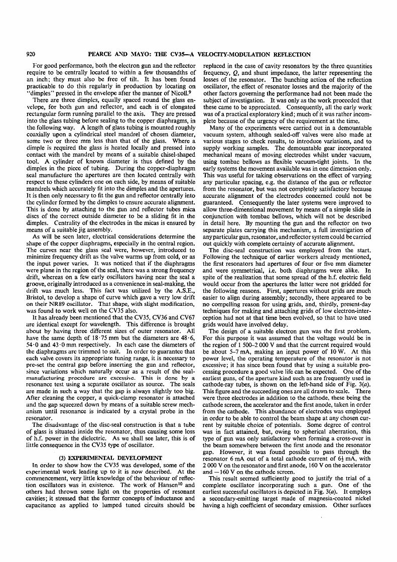
The design of a suitable electron gun was the first problem.For this purpose it was assumed that the voltage would be inthe region of 1 500-2 000 V and that the current required wouldbe about 5-7 mA, making an input power of 10 W. At thispower level, the operating temperature of the resonator is notexcessive; it has since been found that by using a suitable pro-cessing procedure a good valve life can be expected. One of theearliest guns, of the aperture kind such as are frequently used incathode-ray tubes, is shown on the left-hand side of Fig. 3(a).This figure and the succeeding ones are all drawn to scale. Therewere three electrodes in addition to the cathode, these being thecathode screen, the accelerator and the first anode, taken in orderfrom the cathode. This abundance of electrodes was employedin order to be able to control the beam shape at any chosen cur-rent by suitable choice of potentials. Some degree of controlwas in fact attained, but, owing to spherical aberration, thistype of gun was only satisfactory when forming a cross-over inthe beam somewhere between the first anode and the resonatorgap. However, it was found possible to pass through theresonator 6 mA out of a total cathode current of 6£ mA, with2 000 V on the resonator and first anode, 160 V on the acceleratorand —160 V on the cathode screen.
This result seemed sufficiently good to justify the trial of acomplete oscillator incorporating such a gun. One of theearliest successful oscillators is depicted in Fig. 3(a). It employsa secondary-emitting target made of magnesia-coated nickelhaving a high coefficient of secondary emission. Other surfaces
OSCILLATOR FOR WAVELENGTHS OF ABOUT 10 CM 921
W/////,
W//7/A (a)
777777/.
V/////A
W/////.V/////A (c)
Figs. 3 and 4.—Development arrangements,
(<0
such as oxidized aluminium were tried, but it was later foundthat untreated nickel was not inferior. Positive-target valvesoperate mainly by the fact that the target is run at a potentialslightly positive with respect to the cathode, in which conditionthe yield of secondaries is a rapidly-increasing function of theincident velocity of the primaries. Hence, those electrons thatare accelerated during the first transit through the resonatorgenerate more secondaries than the decelerated ones, some ofwhich may not even reach the target. In this way bunches areformed, the correct phase condition being that the electronsreturn to the resonator an integral number of periods n, afterleaving it. Maximum efficiency occurs when the drift length is asshort as practicable, since the electron motion between resonator
and reflector plays no such part in the bunching as it does in theklystron or in a negative-reflector oscillator. If, however, thedrift length is appreciable, as in the case under consideration inwhich n is approximately six, this straightforward state of affairsdoes not exist, because the electron beam is partially bunched bythe time it reaches the target. In the absence of velocity-selectionbunching, the latter mechanism also would return bunches tothe resonator, but the best phase condition is different, namely,that the transit time must be n + i periods. In all our earlyoscillators, both bunching processes were in partial operationsimultaneously.
Outputs of up to 150 mW at about 9 • 1 cm, and at efficiencies ofslightly less than 1 % were obtained with sealed-off tubes of thistype. They all required a high voltage of about 2 700 V, and ahigh input power of between 20 and 30 W, which necessitatedforced air cooling of the resonator. A small number of theseoscillators was, however, made and supplied to Service Depart-ments for bench test purposes.
In this design a concave target was used in an effort to directthe secondaries through the resonator aperture, a condition whichis clearly necessary for high efficiency. Tests showed, however,that a large fraction of the secondaries were not doing this, butwere striking the nearest diaphragm. A great improvement inthis respect was effected by surrounding the target by a cylindricalring operated at a suitable negative potential [Fig. 3(Z>)]. Thiswas tested by replacing the target by an oxide cathode of thesame shape, when about 85% of the current emitted passedthrough the aperture. In spite of this electron-optical improve-ment, several sealed-off oscillators incorporating the ring targetwere at best only just as efficient as the former simple-targetvalves. The potential of the ring did, however, influence theefficiency very noticeably. These phenomena are due to thefact, not fully appreciated at the time, that the ring potentialinfluences not only the efficiency of electron reflection, but alsothe bunching field; this is discussed later. One of these tubeswhich was investigated over a wide voltage range showed fivemodes whose optimum operating conditions and output were asshown in Table 2. All voltages are relative to cathode and theelectrodes are named as specified earlier.
In the highest-voltage mode, in order to limit the input powerto a just safe level, the first anode was run at accelerator instead ofresonator potential. This arrangement was known to producepoor focusing, so that the efficiency of that mode should be some-what increased, if comparison is to be made with the other modes.A rough calculation shows that the drift time of these modes isapproximately 8 periods in the first, decreasing to 4 in the last.
Positive-target valves have one great disadvantage, in that thetarget takes an appreciable negative current of several milli-amperes which varies with the state of loading of the resonator;a stabilized voltage supply for this electrode is therefore required.A subsidiary disadvantage is that secondary-emitting surfacesdeteriorate easily and are difficult to reproduce in production.
Table 2
OPTIMUM OPERATING CONDITIONS FOR DIFFERENT MODES
Res. and firstanode voltage
600840
1 30020004 700*
Ace.voltage
100150200370160
Cathodescreen voltage
000
- 2 0 00
Target voltage
* ••'""+ 2+ 4+ 25+ 75+ 20
Target ringvoltage
00
- 2 5 0- 2 2 0- 4 5 0
Res. curr.(mA)
4-567-5
1010
First anodecurr. (mA)
11-5570
Target curr.(mA)
- 10
- 1- 0 - 5- 0 - 5
Power output(mW)
< 101020
250350
0-15%0-7%0-75%
First anode at accelerator potential.
922 PEARCE AND MAYO: THE CV35—A VELOCITY-MODULATION REFLECTION
Negative-reflector valves, on the other hand, are free from thesedefects, so that negative reflectors were from time to time triedwith the various resonator and gun combinations. The abovevalve, for instance, would operate with the target and ringnegative, and gave about 100 mW output for 1 950 V, 18-5 mAinput. Other reflectors of various forms such as segments ofspherical shells and deep tubes were tried, but generally speaking,at this stage of the development all were inferior to the bestpositive-target valves. Two possible contributory causes ofinefficiency sprang to mind. These were poor reflection, andunequal drift times between marginal and axial electrons.
To study the first of these, a method of estimating electronreflection under non-oscillating conditions was evolved. Forthis the outer resonator is removed so that the currents to thecopper diaphragms can be measured separately. Firstly, thecurrents to the reflector, 7,, to the reflector-end diaphragm, 72,and to the gun-end diaphragm, 73, are measured with bothdiaphragms at the usual resonator potential and the reflectorabout six volts more positive. This condition has been found,by checking with a Faraday cage in place of the usual reflector,to give a result least disturbed by secondaries. If the reflectoris much more than six volts positive, it collects secondaries fromthe nearest diaphragm without returning any to it, so that 7,is too big and 72 too small (it may even be negative). If, onthe other hand, the reflector is much less than six volts positive,say, for example, actually at the same potential as the resonator,then it will, if of the flat dish form frequently used, return moresecondaries to the diaphragm than it receives, so that 7t is toosmall and 72 too great. At about six volts the net interchangeof secondary current between the two electrodes is approximatelyzero. We now switch the reflector potential to its usual negativevalue and measure the diaphragm currents again. Call these/2 and /3. Then assuming that this change of potential does notaffect the current leaving the cathode, the current reflectedthrough the reflector end diaphragm, which is the useful currentin the oscillator, is given by 7! — (i2 — 72).
The assumption made here, however, is not strictly correct.In the second case the total current (i2+ i3) is usually some ten totwenty per cent less than the total current (7j + 72 + 73) in thefirst case. This shows that some electrons are reflected backeither close to or actually on to the cathode; in either case, theprimary emission is thereby lessened. The useful current mayexceed the current (/2 + /3) if obstruction by the resonator issmall. The method may be criticized on several other groundsbut nevertheless it has been found to give a reliable measure ofthe amount of useful current available. On applying the test tothe negative reflector oscillators then under development, theuseful current was found to be as low as 50 % of the total current.
With regard to unequal drift times between axial and marginalrays, this is most likely to occur in a beam which is divergingrapidly as it leaves the resonator. Such a beam would also beexpected to be difficult to reflect, especially with diaphragms ofthe shape then in use [Figs. 3(a) and 3{b)]. Hence it was feltthat the aperture gun, which produced a beam that crossed overand thereafter diverged, might be accentuating the difficulty ofobtaining good reflection and equal transit times. Conse-quently, attention was turned to designing a gun to produce aless convergent beam. As a result, a number of reasonably gooddesigns of gun of both the apertured diaphragm and the tubulartypes was evolved. One of the latter is shown to scale in Fig. 3(c).The cathode of 6-mm diameter was slightly larger than theresonator aperture and was far enough away for the beam,which was approximately of the shape shown in dotted line, toclear the diaphragms and be almost parallel at the gap. At2 000 V this gun transmitted over 90% of a total current of6 mA, but required a negative bias on both electrodes near the
cathode in order to produce the necessary field curvature. Analmost parallel beam of this sort is clearly easy to reflect andleast likely to cause a difference of phase between marginal andaxial electrons in the drift space. On incorporating this gun intoa negative-reflector oscillator, the result was a somewhat greaterefficiency than previously at a slightly lower voltage, but althougha number of different reflectors were tried, the best efficiencyattainable was still less than 1 %.
In view of this result, attention was then turned to anotherfactor that was known to influence efficiency, namely, the potentialdistribution of the reflecting space. It was realized that thiswould considerably affect the degree of bunching. IndeedMr. S. Hill pointed out that with a reflecting field having asquare-law potential variation along the axis, no bunching atall would occur, all electrons taking the same transit time irre-spective of their initial velocities. Hitherto the shape of the fieldhad been controlled mainly by the trumpet-shaped diaphragms.These prevented good bunching and had two further disadvantages.First, a short drift length could not be used although there hadbeen indications that this was necessary, and secondly, efficientreflection could not be obtained. Consequently, the shapes ofthe diaphragms were changed to those shown in Fig. 4(a); herethe two diaphragms are dissimilar, the target-end one having aflat central portion of about 8 mm diameter surrounding theaperture so that, if necessary, reflectors could be brought up closeto the resonator gap. The other diaphragm was still trumpet-shaped in order to keep down the capacitance of the resonator asmuch as possible. In the first oscillators employing thesediaphragms an extra electrode in the form of a ring was intro-duced into the reflecting space in order to control the field shape,''and a spherical reflector was used.
As a result of these changes a negative-reflector valve wasproduced which, for the first time, gave an efficiency of about11%, 120mW output being obtained at 1 800 V, 4 mA input,with the reflector at —250 V and the reflector ring at zeropotential. The reflector ring voltage had, as expected, an appre-ciable effect on the efficiency, having a broad optimum at aboutcathode potential. In other tubes this optimum occurred atdifferent potentials depending upon the geometry. Simplerreflectors not having a ring gave lower efficiencies of about 1 %,but still slightly better than with former oscillators.
The position thus far was that using resonators having 4 or5 mm apertures, the best that could be done with negative-reflector valves seemed to be an output of 100-150 mW at anoverall voltage of 2 000 or more, and an input power of 10 ormore watts. This performance was not as good as desired, forthe output seemed rather marginal when allowance was madefor the usual scatter in production; moreover, the overall voltagewas higher than desirable.
By this time., however, our colleague, M. B. Manifold, wasdeveloping an extension of the theory of Webster12 for especialapplication to the reflection oscillator; it took into accountthe finite power loss in the resonator, the non-linear shape of thefield in the reflector space, and the finite time of transit of theelectrons through the resonator. Among other things a methodwas developed of computing the effect of the latter by numericalintegration from the field plots of a scaled-up model of the systemtaken in an electrolytic tank.13 This showed that with a 5-mmaperture the interchange of energy between the beam and theresonator was very poor, and that to improve matters it wouldbe necessary to decrease the aperture size considerably. Such astep would also lessen the capacitance of the resonator and hencethe copper losses, and so improve efficiency. The theory alsoshowed that under these conditions, in order to avoid over-bunching, it would be necessary to modify the reflecting field inthe direction of shorter drift length.
OSCILLATOR FOR WAVELENGTHS OF ABOUT 10 CM 923
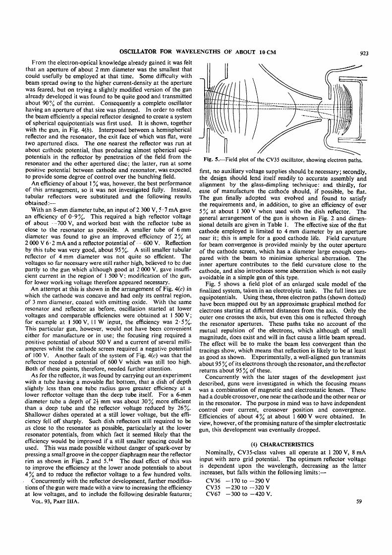
From the electron-optical knowledge already gained it was feltthat an aperture of about 2 mm diameter was the smallest thatcould usefully be employed at that time. Some difficulty withbeam spread owing to the higher current-density at the aperturewas feared, but on trying a slightly modified version of the gunalready developed it was found to be quite good and transmittedabout 90 % of the current. Consequently a complete oscillatorhaving an aperture of that size was planned. In order to reflectthe beam efficiently a special reflector designed to create a systemof spherical equipotentials was first used. It is shown, togetherwith the gun, in Fig. 4(b). Interposed between a hemisphericalreflector and the resonator, the exit face of which was flat, weretwo apertured discs. The one nearest the reflector was run atabout cathode potential, thus producing almost spherical equi-potentials in the reflector by penetration of the field from theresonator and the other apertured disc; the latter, run at somepositive potential between cathode and resonator, was expectedto provide some degree of control over the bunching field.
An efficiency of about 1 % was, however, the best performanceof this arrangement, so it was not investigated fully. Instead,tubular reflectors were substituted and the following resultsobtained:—
With an 8-mm diameter tube, an input of 2 300 V, 5 • 7 mA gavean efficiency of 0-9%. This required a high reflector voltageof about 700 V, and worked best with the reflector tube asclose to the resonator as possible. A smaller tube of 6 mmdiameter was found to give an improved efficiency of 2% at2 000 V 6 • 2 mA and a reflector potential of - 600 V. Reflectionby this tube was very good, about 95%. A still smaller tubularreflector of 4 mm diameter was not quite so efficient. Thevoltages so far necessary were still rather high, believed to be duepartly to the gun which although good at 2 000 V, gave insuffi-cient current in the region of 1 500 V; modification of the gun,for lower working voltage therefore appeared necessary.
An attempt at this is shown in the arrangement of Fig. 4(c) inwhich the cathode was concave and had only its central region,of 3 mm diameter, coated with emitting oxide. With the sameresonator and reflector as before, oscillation started at lowervoltages and comparable efficiencies were obtained at 1 500 V;for example at 1 500 V, 11 W input, the efficiency was 2 • 5 %.This particular gun, however, would not have been convenienteither for manufacture or in use; the focusing ring required apositive potential of about 500 V and a current of several milli-amperes whilst the cathode screen required a negative potentialof 100 V. Another fault of the system of Fig. 4(c) was that thereflector needed a potential of 600 V which was still too high.Both of these points, therefore, needed further attention.
As for the reflector, it was found by carrying out an experimentwith a tube having a movable flat bottom, that a dish of depthslightly less than one tube radius gave greater efficiency at alower reflector voltage than the deep tube itself. For a 6-mmdiameter tube a depth of 2\ mm was about 30 % more efficientthan a deep tube and the reflector voltage reduced by 26%.Shallower dishes operated at a still lower voltage, but the effi-ciency fell off sharply. Such dish reflectors still required to beas close to the resonator as possible, particularly at the lowerresonator potentials, from which fact it seemed likely that theefficiency would be improved if a still smaller spacing could beused. This was made possible without danger of spark-over bypressing a small groove in the copper diaphragm near the reflectorrim as shown in Figs. 2 and 5.14 The dual effect of this wasto improve the efficiency at the lower anode potentials to about4% and to reduce the reflector voltage to a few hundred volts.
Concurrently with the reflector development, further modifica-tions of the gun were made with a view to increasing the efficiencyat low voltages, and to include the following desirable features;
VOL. 93, PART IIIA.
Fig. 5.—Field plot of the CV35 oscillator, showing electron paths.
first, no auxiliary voltage supplies should be necessary; secondly,the design should lend itself readily to accurate assembly andalignment by the glass-dimpling technique: and thirdly, forease of manufacture the cathode should, if possible, be flat.The gun finally adopted was evolved and found to satisfythe requirements and, in addition, to give an efficiency of over5 % at about 1 300 V when used with the dish reflector. Thegeneral arrangement of the gun is shown in Fig. 2 and dimen-sional details are given in Table 1. The effective size of the flatcathode employed is limited to 4 mm diameter by an aperturenear it; this is ample for a good cathode life. Field curvaturefor beam convergence is provided mainly by the outer apertureof the cathode screen, which has a diameter large enough com-pared with the beam to minimize spherical aberration. Theinner aperture contributes to the field curvature close to thecathode, and also introduces some aberration which is not easilyavoidable in a simple gun of this type.
Fig. 5 shows a field plot of an enlarged scale model of thefinalized system, taken in an electrolytic tank. The full lines areequipotentials. Using these, three electron paths (shown dotted)have been mapped out by an approximate graphical method forelectrons starting at different distances from the axis. Only theouter one crosses the axis, but even this one is reflected throughthe resonator apertures. These paths take no account of themutual repulsion of the electrons, which although of smallmagnitude, does exist and will in fact cause a little beam spread.The effect will be to make the beam less convergent than thetracings show, which means that reflection is likely to be at leastas good as shown. Experimentally, a well-aligned gun transmitsabout 95 % of its electrons through the resonator, and the reflectorreturns about 95 % of these.
Concurrently with the later stages of the development justdescribed, guns were investigated in which the focusing meanswas a combination of magnetic and electrostatic lenses. Thesehad a double crossover, one near the cathode and the other near orin the resonator. The purpose in mind was to have independentcontrol over current, crossover position and convergence.Efficiencies of about 4% at about 1 600 V were obtained. Inview, however, of the promising nature of the simpler electrostaticgun, this development was eventually dropped.
(4) CHARACTERISTICSNominally, CV35-class valves all operate at 1 200 V, 8 mA
input with zero grid potential. The optimum reflector voltageis dependent upon the wavelength, decreasing as the latterincreases, but falls within the following limits:—
CV36 -170 to -290 VCV35 -230 to-32OVCV67 -300 t o - 4 2 0 V.
59
924 PEARCE AND MAYO: THE CV35—A VELOCITY-MODULATION REFLECTION
Jn practice a wide departure from the nominal input conditionsmay be made before the efficiency is much affected, as may be seenfrom the curves of Figs. 6, 7 and 8, which were taken on a typical,but not first-class CV35 specimen. For each set of observa-
800
600
^400
J
ys
i
/
i—•
A
J 4/—->a
^ ^
800 1000 1200 1400 1600Resonator voltage, V.
1800 2000
Fig. 6.—Variation of output and efficiency with resonator voltage.
300
^200
io 100
0
/
/
/
/
/
200
/
,
250
-v
\
\
[
\
300 35Reflector volt age ,V
Fig. 7.—Variation of output with reflector voltage.
2400
£300— —
-~
,-—- 1
_ .
a
9-8 10- 10 29-9 100o Wavelength, cm
Fig. 8.—Variation of output and reflector voltage with wavelength.
tions, the bias was first adjusted to a value that would makethe input exactly 10 W at an anode voltage of 1 300 and optimumreflector voltage, and was then left at that value. The wave-length for Figs. 6 and 7 was set to 10 0 cm. Fig. 6 shows thevariation of output with anode voltage under two conditions:
(«) with the reflector voltage constant, and(/>) with the reflector voltage adjusted to optimum at every
anode voltage.
The load consisted of a coaxial line of 75 ohms characteristicimpedance, approximately matched at its end and coupled intothe resonator by means of a loop of area about 35 mm2. In
both cases the position of the loop was adjusted for each testcondition to give a maximum output. It will be seen thatoscillation occurs over a broad band, especially in case (b).Curve (c) of the same figure shows the efficiency for case (b) asa function of anode voltage. It varies very little between 1 000and 2 000 V, but does have an optimum at about 1 500 V inthis particular valve. If the coupling is not adjusted, but leftconstant at the optimum value for the nominal input conditions,the efficiency falls off at both ends rather more steeply than incurve (c). 800 V is the lowest usable anode voltage in an averagevalve.
Fig. 7 shows the variation of output with reflector voltage.The variation here is more marked, as we should expect from thefact that the reflector voltage exercises more control over transittime than the anode voltage, but even so, the total oscillatingrange is 160 V on a mean potential of — 255 V. As we gothrough this range the frequency varies, but only very slightly, infact by about 4 Mc/s from half power on one side of the peak tohah0power on the other side. Variation of frequency with anodevoltage is on an equally small scale, being approximately 6 Mc/sfrom 800 to 1 600 V. The oscillator is thus suitable as a stablesource, but unsuitable for any application involving electronictuning by voltage adjustments.
In Fig. 8 we see how the output varies over the tuning range ofthe valve [curve (a)]. Although it is relatively flat, there is aperceptible dip at the short-wavelength end. This occurs wherethe tuning plungers are fully inserted into the circuit. It hasbeen found that in this position the Q of the resonator is appre-ciably lowered, indicating increased resonator loss, which issufficient to account for most of the dip. Curve (b) shows howthe optimum reflector voltage decreases steadily with increasingwavelength.
The grid-electrode characteristic, which is of interest if thevalve is being modulated, shows a current cut-off at about— 110 V. Oscillation ceases, however, before that point at avoltage of about — 40 V when the current is 1£ mA. If we takethis value as the "starting current" of the oscillator, the ratiooperating current/starting current is about 6, which agrees wellwith the k value computed later.
Another characteristic that is of interest in some applicationsis the frequency drift. This is very low; from cold to the equili-brium value in still air the frequency changes only a matter of afew megacycles/sec, usually less than three.
The life of the valve under normal conditions is over 1 000hours.
(5) DISCUSSION—THE FUNDAMENTAL ENTITIES INVOLVEDA complete first-order theory of the reflection oscillator has
been given in a paper by N. C. Barford and M. B. Manifold13
which will be published in Part III of the Journal. This theoryis used here as a basis for a brief discussion of the effects of thevarious fundamentals involved, without, however, entering into acomprehensive discussion of the behaviour of reflection oscillatorsin general. M.K.S. units are employed.
At a given frequency / ( - - (D/2TT) the entities which govern theperformance of a reflection oscillator are the following:—
The d.c. input voltage, Vo, the input current, ;0, the beam-resonator coupling factor, /3, the effective shunt impedance acrossthe gap of the resonator, R, and factors depending upon theproperties of the reflecting field. We assume that the anode andreflector voltages are such that the transit-time condition issatisfied and that the load coupled to the oscillator is theoptimum one.
Barford and Manifold show that the effect of the reflectorfield is expressible in terms of two parameters, one the driftlength s (from the centre of the gap to the reflecting equipotential
OSCILLATOR FOR WAVELENGTHS OF ABOUT 10 CM 925
and back) and the other a factor F', a dimensionless quantitywhich depends solely upon the shape of the field, i.e., the distri-bution of potential along the axis when normalized so thatabsolute potentials and distances are not involved. The effi-ciency 7) is expressed in terms of two compound parameters kand C and is given by the equation:—
where x is the root of the equation J0(x) =- 1/k . . . (2)
k ^ 1 - 6 8 x l O - ^ R i o o F ' s V f * . . . ( 3 )
and C - 1-68 x lO- (4)
The constant is the value of \/(m/2e) for an electron, / is theuseful electron current and VB is the d.c. potential at the centre ofthe gap; this is slightly less than Vo in an ungridded tube. Achart in the paper shows how 77 depends upon k and C. Ingeneral, rj 0 at k -- 1 and increases as k increases until itreaches a flat maximum for large values of k. t] is inverselyproportional to C. Hence for a high efficiency we need a highvalue of k and. a low value of C, although little is to be gainedby making k greater than ten. As a matter of interest, it maybe mentioned that k is numerically equal to the ratio of theoperating current to the unloaded starting current.
From eqn. (3) we see straight away that whatever the valuesof F', s, and VB (provided that k > 1), the efficiency increaseswith the product fi2Ri since these factors are involved only ink and not in C As for /, this is usually determined, like Vo,by other considerations, such as power input, the purpose forwhich the oscillator is intended, etc. It cannot therefore berigidly specified, but it should clearly be as high a proportion ofthe total input current as possible. In order to maximize fP-Rthe following considerations must be taken into account.
The factor j8 depends upon the transit time of an electronthrough the h.f. field at the gap, and approaches its maximumvalue of unity as the transit time becomes a small fraction ofthe periodic time. Its definition and computation are given inthe Barford and Manifold paper. It is sufficient for the presentpurpose to note that a high value of /? requires a small aperturediameter and a small gap. The former usually has a limit set,as we have seen earlier, by electron-optical considerations.
We now consider R. This is made up of two parts which maybe envisaged as being in parallel at the gap, one representingcopper and dielectric losses in the resonator and the other repre-senting beam damping of the resonator, which is due to the finitepower required to impart velocity modulation to the beam. Aswe shall see later, the latter is not very important in the CV35,and was in fact neglected in all the early calculations. Regardingthe resonator copper losses, these are least in a resonator of highinductance/capacitance ratio, so that for high R we require asmall capacitance at the gap. This means a small aperture anda large gap; the first coincides with the /$ requirement, but thelatter is in opposition to it. Hence, for any resonator thereexists a particular gap where j82i? is a maximum, but the latteris not a rapidly-varying function of gap. Since resonators areoften of such a shape as not to lend themselves readily to impe-dance calculations, the best gap is usually determined experi-mentally.
The total resonator loss in the CV35 is not very serious, and islargely due to the presence of the glass in the resonator. Measure-ment of the Q gives about 1 300 for the CV35 resonator, but about4 000 to 5 000 for a similar resonator with no glass inside. Hence,the shunt impedance, which is roughly proportional to thesevalues, is reduced by a factor of about three times owing to the
glass. The impedance has been measured directly by a methodwhich consists, in essence, in measuring the resonant wavelengthas a function of the outside diameter of the resonator, leaving thecentral portion undisturbed. By this means a value for theequivalent inductance is found, which when combined with theQ measurement gives the shunt impedance by using the lumpedresonant circuit formula R = OJLQ. The value obtained isR = 70 000 ohms.
So far we have neglected beam damping. This can be cal-culated, and is found to have a value of 700 000 ohms. Incomparison with the 70 000 due to resonator losses, this is almostnegligible.
We now consider the reflecting field. Here we have to satisfyconditions that may be divided into two classes, those concernedwith electron optics, and those concerned with efficient bunching.They may occasionally conflict, but we have already seen inSection 3 the conditions that appear to be necessary for goodreflection and uniformity of drift time, so we now deal only withthe second class.
It has already been remarked, and confirmed experimentally,that the shape of the reflecting field is an important factor inefficiency. The effect can be seen more precisely from thetheory. Representing the reflecting-field properties are the twofactors F' and s. Both are obtained from a field plot such asFig, 5, s by direct measurement, while to determine F' a plot ofthe potential along the axis, such as that shown in Fig. 9 for theCV67, is needed. Both co-ordinates have been normalized insuch a way that the gap centre is the point (0-5, 10), the zeroreflecting equipotential being the origin. In general the computa-tion of F' depends very largely upon the slope of the potentialcurve at the zero equipotential, a small slope leading to a high F'and a large slope to a small F'. This slope is determined mostlyby the reflector depth in relation to its diameter, and its potential.A deep reflector and a low potential give a low slope and a highF' and vice versa.
Eqns. (3) and (4) show that F' enters into the efficiency only incombination with s in the form of the product F's. The firsteffect of this is that F' and s are in a sense complementary; forinstance the same efficiency can be achieved with a short driftlength and a large F' as with a long drift length and a smaller F'.In order to have voltage insensitivity, the former condition isnecessary, as in the CV35. Secondly, the product enters intoboth k and C in the same way. Hence, for small F's we have asmall k and a small C leading to low efficiency and for largeF's a large k and a large C which also leads to low efficiency.Somewhere in between at a value depending upon the otherfundamental quantities is the optimum F's. This was deter-mined in the CV35 as already related by trial of various reflectors,but present-day technique would rely on more theoreticalguidance in computing the value required for any particularoscillator.
It is clear from the foregoing that a change in F' such as maybe produced by a small change in the reflector-space conditionsmay alter the efficiency very considerably.
In the CV35 and most other reflection oscillators, the bunchingis of what may be termed a negative kind, in which those electronsthat are accelerated at the gap have a longer drift time than thedecelerated ones; the transit time condition is then n -f i periodsand F' is positive. If the potential curve follows a square law ofthe form VB—V~ Ax2 where Fis the potential on the axis at adistance x from the centre of the resonator gap, VB is the potentialat x — 0, and A is a constant, then there is no bunching and F' iszero. If on the other hand V is greater than the value given bythis formula, then a positive bunching condition obtains inwhich the accelerated electrons spend less time in the field thanthe decelerated ones: F' is then negative and the transit time con-
926 PEARCE AND MAYO: THE CV35—A VELOCITY-MODULATION REFLECTION
dition is n + \ periods. The two-resonator klystron providesan example of this bunching mechanism. Some of our earlyreflection oscillators having elongated trumpet-shaped dia-phragms and shallow reflectors operated in this way.
(6) THEORETICAL EFFICIENCY AND STABILITYCONSIDERATIONS
In order to calculate the theoretical efficiency we need to ascer-tain the numerical values of the various fundamental entitiesused in eqns. (3) and (4). The following relates to the CV67 at awavelength of 9 • 1 cm. The factor j3 has been calculated bytwo separate methods and fairly close agreement at a value of0-90 obtained. R has been shown to be 64 000 ohms while/ has been found to be equal to the input current which is8-3 mA. A field plot shows that for Vo = 1 200, the voltageat the centre of the gap VB is 1 070. Fig. 9 is used to com-pute F' and a value of 2-36 obtained. The distance s is readoff directly from the field plot, the result being 5-65 x 10~3 m.Finally the angular frequency o» is 2 07.1010 (for 9 10cmwavelength).
Inserting these values in eqns. (3) and (4) we get
C - 14-2
From these, using the chart drawn from eqns. (1) and (2), wefind the efficiency to be 5 • 7. When allowance is made, however,for the fact that the actual input power is in excess of the usefulinput power because Vo exceeds VB, then the efficiency falls toan overall value of 5 • 1 %.
In practice, for well-aligned valves, efficiencies up to 5-5%have been observed using lamp power indicators. The theory isonly a first order theory, i.e., the h.f. voltage across Ihe resonatorgap is assumed to be negligibly small compared with the d.c.input voltage, which is known not to be the case, so that weshould not expect a result of high accuracy. In view of this andthe uncertainties of R and /, the agreement between theory andexperiment is close.
We are now in a position to consider the stability of theoscillator. In the first place the value of 5 • 7 for k is in the regionwhere the efficiency is not a rapidly-varying function of k.Hence appreciable changes in any one of the fundamentalentities, for instance R or /, will not affect the efficiency to anymarked degree. This feature of the CV35 is important in manu-facture where some variation of spacings, etc., is inevitable.Insensitivity to output coupling and to change of wavelengthis also largely due to the high k value.
The second aspect of stability is the insensitivity of the oscil-lator to change of supply voltages, well illustrated by Figs. 6 and7, particularly the former, which shows that if all other voltagesare left constant, oscillation takes place continuously over aresonator voltage band of about 800 V, and that if the reflectorvoltage is suitably adjusted the efficiency varies little between1 000 and 2 000 V. At first sight this appears to be at variancewith the discrete voltage condition mentioned earlier. Theresults may however be understood if the following three con-siderations are taken into account. First, the transit time in thereflector space is short. A calculation from the potential curveof Fig. 9 by numerical integration13 shows it to be \\ periods.Clearly the shorter the transit time the less will the phase of thereturning bunches be removed from the optimum value by agiven variation of say reflector or anode voltage. Secondly,the fact already mentioned, that k is high, means that theefficiency is not very sensitive to change of VB or to the phase ofthe returning electron bunches. The third factor mainly concernsthe effect of the anode voltage on the phase; it is the shape of thereflecting field and the potential at which the reflector is run.
1-2
10
0-4
02/
/
/
/
/
/
//
/f
Centre'of
•resUlldL ap-
0-2 04 0-6Distance
08
Fig. 9.—Axial potential between resonator and reflector for aCV67 valve.
It has been shown15 that if the field is linear then the transit timeis invariant to a first order of accuracy with Vo if the reflectorpotential VR is equal to — Vo. The physical meaning of this isthat if, say, the resonator voltage is increased, the speed of theelectrons is increased, but so is the distance they have to travelto the reflecting equipotential and the two neutralize one anotherwhen VR equals — VQ. In the case of a non-linear field such asthe one we are dealing with here, we may get invariance at someother reflector potential, the value of which depends largely uponthe slope of the potential curve at the zero equipotential. If thisis less than for a linear field then the value of \VR\ will usuallybe less than Vo. In the CV35, \VR\ is about iV0 but the resultsshow that we are fairly near to satisfying the invariancecondition.
As a matter of interest it is easy to compute the magnitude ofthe maximum alternating voltage impressed upon the beam fromthe h.f. power generated and the effective resonator impedance.131
Under conditions of normal optimum loading this is about 150 Vfor a well-aligned valve. Clearly then, the potential of thereflector must always be at least that amount negative, otherwisethe most accelerated electrons will strike the reflector, thusgenerating secondaries which will arrive at the gap in some inde-terminate phase and may produce inefficiency. Moreover,,reflector current will then be drawn and this may cause a dropof potential since the reflector supply circuit is normally ahigh-impedance one. Instability of operation then ensues.If the oscillator is only slightly loaded the peak voltage may riseto about twice the figure given above and the effect is worsened.Instability of this kind has been observed at the longer wave-lengths of the CV36 where the reflector voltage is least, underconditions of light loading.
We may also readily calculate the fraction of the total generatedh.f. power which passes into the load at optimum coupling.Taking the CV67 at a wavelength of 9 • 1 cm, for example,,theory shows that at optimum coupling the load is equivalentto a resistance of 27 000 ohms at the gap. We have already seen,that the resonator impedance due to all forms of loss is equivalentto 64 000 ohms; hence about 30% of the power is lost internally.With the disc-seal construction, this internal loss of powercannot be appreciably reduced, since it is mainly dielectric loss.With this condition, and for voltages in the region considered,the theory shows little possibility of changing the design of theCV35 to produce an appreciably greater efficiency.
OSCILLATOR FOR WAVELENGTHS ABOUT 10 CM 927(7) ACKNOWLEDGMENTS
The authors wish to express their indebtedness to their col-leagues and in particular to Dr. L. F. Broadway for manyvaluable suggestions throughout the course of the work and toMr. G. E. Condliffe for his continued interest. Thanks are dueto Mr. 1. Shoenberg, Director of Research of Electric andMusical Industries, Limited, for permission to publish this paper,and to the Board of Admiralty, under whose auspices theoscillator was developed.
(8) REFERENCES(1) LINDER: Proceedings of the Institute of Radio Engineers,
1936, 24, p. 633, and 1939, 27, p. 732.(2) HAHN and METCALF: Proceedings of the Institute of Radio
Engineers, 1939, 27, p. 106.(3) VARIAN, R. H. and S. F.: Journal of Applied Physics, 1939,
27, p. 321.(4) British Patent No. 535767.
(5) British Patent No. 201514.(6) British Patent No. 474706.(7) BROADWAY, L. F. et al.\ "Velocity-Modulation Valves."
See page 855.(8) British Patent No. 574997.(9) British Patent Nos. 507840 and 575027.
(10) HANSEN: Journal of Applied Physics, 1938, 9, p. 654.HANSEN and RICHTMYER: Journal of Applied Physics,1939,10, p. 189.
(11) British Patent No. 574972.(12) WEBSTER: Journal of Applied Physics, 1939, 10, pp. 501
and 864.(13) BARFORD, N. C , and MANIFOLD, M. B.: "Elementary
Theory of Velocity Modulation Systems." Radio SectionPaper to be published in Part III of the Journal.
(14) British Patent No. 576126.(15) PIERCE, J. R.: Proceedings of the Institute of Radio Engineers,