The de Mello Foundation Engineering Legacy Harry G. Poulos Abstract. This paper reviews the contributions of the late Victor de Mello to foundation engineering and attempts to highlight the insights that he provided in a number of key areas, including foundation design principles, the bearing capacity of shallow foundations, the axial load capacity of deep foundations, and the behaviour of foundations incorporating settlement reducing piles. In each case, de Mello challenged some of the existing concepts and as a consequence, subsequent research has clarified the profession’s understanding and has led to the development and implementation of improved methods of design. Some examples of developments in the above areas, and their application to practice, are described. Keywords: bearing capacity, design criteria, foundations, piles, piled raft, settlement. 1. Introduction The late Victor de Mello was no ordinary man. He was not only one of the world’s pre-eminent geotechnical engineers, but also a person with an enormous breadth and depth of knowledge, and with passionate but considered views of many aspects of human society and existence. As a consequence, he was a vibrant and stimulating colleague and friend. His personal qualities have been described fully and eloquently by Professor John Burland in his first de Mello Lecture (Burland, 2008) and I can only add that I was privileged, as was Professor Burland, to have the encour- agement of this giant of our profession in the early stages of my career. He was extraordinarily well-read, both in his professional field and in many other areas of intellectual endeavour, and could debate with equal authority the finer points of soil behaviour and the competing virtues of vari- ous philosophers of the enlightenment. De Mello was an expert in several areas of geotech- nical engineering, and in particular, embankment dams, and his 1977 Rankine Lecture dealt with this topic in an au- thoritative and expansive way. He also had a major influ- ence on foundation engineering, and it is this aspect that will be explored in this paper. In particular, there are two pivotal papers that will be referred to frequently here, his State of the Art Report at the 7 th International Conference in Mexico City in 1969, entitled “Foundations of Buildings in Clay”, and his General Report with Burland & Broms at the 9 th International Conference in Tokyo entitled “Behaviour of Foundations and Structures”. An indication of his breadth of reading is evidenced by the very large number of references in these papers, 344 in the first and 333 in the second. Mention can also be made here of his epic treatise on the Standard Penetration Test (de Mello, 1971) which contained no less than 353 references, his 1994 Terzaghi Oration at the 13 th International Conference in New Delhi, and in a different vein, his paper in 2000 uniquely entitled “Overview of hypotheses not plucked or pursued. Merit re- canting or rechanting?” I will attempt in this paper to summarize the engineer- ing philosophy of Victor de Mello and then to examine some areas within foundation engineering in which he made notable contributions, and in which he identified shortcomings. The questions that he raised have been ad- dressed subsequently by both researchers and practitioners, and have led to a better understanding of foundation behav- iour and to more robust practical methods of analysis and design. The areas that will be discussed include the bearing capacity of shallow foundations, the load capacity and set- tlement of piles under axial loading, and the behaviour and design of settlement reducing piles. 2. Some Aspects of the De Mello Philosophy 2.1. Broad views Victor de Mello expounded his philosophical views on a number of issues, some related directly to foundation engineering, and some to broader issues of design, educa- tion and the role of the engineer in society. Burland (2008) succinctly summarized de Mello’s philosophy in terms of five Design Principles (DP). These were oriented towards embankment dam design, but can perhaps be generalised as follows: 1. DP1 - Aim to design out any risk from behaviour triggered by local phenomena – Robustness. 2. DP2 - Use a dominant feature to cut across uncer- tainties – Change the problem 3. DP3 - Aim at homogenization – Redundancy. 4. DP4 - Minimize rapid uncontrolled loading – Ob- servational control. 5. DP5 - Question each design assumption and the consequences of departure from it – Ask “what if” ques- tions. Beyond these broad design principles, there were a number of other viewpoints that de Mello expressed (often very forcefully), and a small selection of these views is pre- sented below, based on his published papers. Most of the Soils and Rocks, São Paulo, 34(1): 3-31, January-April, 2011. 3 Harry G. Poulos, Coffey Geotechnics, Sydney, Australia. e-mail: [email protected]. Submitted on February 8, 2011; Final Acceptance on February 21, 2011; Discussion open until August 31, 2011.
Transcript
The de Mello Foundation Engineering Legacy
Harry G. Poulos
Abstract. This paper reviews the contributions of the late Victor de Mello to foundation engineering and attempts to highlight theinsights that he provided in a number of key areas, including foundation design principles, the bearing capacity of shallowfoundations, the axial load capacity of deep foundations, and the behaviour of foundations incorporating settlement reducingpiles. In each case, de Mello challenged some of the existing concepts and as a consequence, subsequent research has clarified theprofession’s understanding and has led to the development and implementation of improved methods of design. Some examplesof developments in the above areas, and their application to practice, are described.Keywords: bearing capacity, design criteria, foundations, piles, piled raft, settlement.
1. Introduction
The late Victor de Mello was no ordinary man. Hewas not only one of the world’s pre-eminent geotechnicalengineers, but also a person with an enormous breadth anddepth of knowledge, and with passionate but consideredviews of many aspects of human society and existence. As aconsequence, he was a vibrant and stimulating colleagueand friend. His personal qualities have been described fullyand eloquently by Professor John Burland in his first deMello Lecture (Burland, 2008) and I can only add that I wasprivileged, as was Professor Burland, to have the encour-agement of this giant of our profession in the early stages ofmy career. He was extraordinarily well-read, both in hisprofessional field and in many other areas of intellectualendeavour, and could debate with equal authority the finerpoints of soil behaviour and the competing virtues of vari-ous philosophers of the enlightenment.
De Mello was an expert in several areas of geotech-nical engineering, and in particular, embankment dams,and his 1977 Rankine Lecture dealt with this topic in an au-thoritative and expansive way. He also had a major influ-ence on foundation engineering, and it is this aspect thatwill be explored in this paper. In particular, there are twopivotal papers that will be referred to frequently here, hisState of the Art Report at the 7th International Conference inMexico City in 1969, entitled “Foundations of Buildings inClay”, and his General Report with Burland & Broms at the9th International Conference in Tokyo entitled “Behaviourof Foundations and Structures”. An indication of hisbreadth of reading is evidenced by the very large number ofreferences in these papers, 344 in the first and 333 in thesecond. Mention can also be made here of his epic treatiseon the Standard Penetration Test (de Mello, 1971) whichcontained no less than 353 references, his 1994 TerzaghiOration at the 13th International Conference in New Delhi,and in a different vein, his paper in 2000 uniquely entitled“Overview of hypotheses not plucked or pursued. Merit re-canting or rechanting?”
I will attempt in this paper to summarize the engineer-ing philosophy of Victor de Mello and then to examinesome areas within foundation engineering in which hemade notable contributions, and in which he identifiedshortcomings. The questions that he raised have been ad-dressed subsequently by both researchers and practitioners,and have led to a better understanding of foundation behav-iour and to more robust practical methods of analysis anddesign. The areas that will be discussed include the bearingcapacity of shallow foundations, the load capacity and set-tlement of piles under axial loading, and the behaviour anddesign of settlement reducing piles.
2. Some Aspects of the De Mello Philosophy
2.1. Broad views
Victor de Mello expounded his philosophical viewson a number of issues, some related directly to foundationengineering, and some to broader issues of design, educa-tion and the role of the engineer in society. Burland (2008)succinctly summarized de Mello’s philosophy in terms offive Design Principles (DP). These were oriented towardsembankment dam design, but can perhaps be generalised asfollows:
1. DP1 - Aim to design out any risk from behaviourtriggered by local phenomena – Robustness.
2. DP2 - Use a dominant feature to cut across uncer-tainties – Change the problem
5. DP5 - Question each design assumption and theconsequences of departure from it – Ask “what if” ques-tions.
Beyond these broad design principles, there were anumber of other viewpoints that de Mello expressed (oftenvery forcefully), and a small selection of these views is pre-sented below, based on his published papers. Most of the
Soils and Rocks, São Paulo, 34(1): 3-31, January-April, 2011. 3
Harry G. Poulos, Coffey Geotechnics, Sydney, Australia. e-mail: [email protected] on February 8, 2011; Final Acceptance on February 21, 2011; Discussion open until August 31, 2011.
quotations are self-explanatory and require little or no com-ment.
2.2. False conclusions from data
De Mello was highly critical of people who drew in-appropriate conclusions from available data, and illustratedhis point with the following example (de Mello, 1984):
“Most persons die in bed; therefore bed is the singlemost dangerous place for humans”.
2.3. Use and abuse of statistics
Statistics was viewed by de Mello as a useful tool butone that was frequently mis-used or abused. The followingquotation sets out his views on this subject.
“We must shun statistics at random, and choose to ap-ply statistical adjustments to our reasonable theories. Thetemporary application of a presumed theory does not pre-clude that it is not satisfactory, and consequently revising it,or even proposing an entirely different one; what cannot becondoned is the attempt to extract conclusions from data atrandom and spurious statistics, without any theory, how-ever nominal, or any design and purpose, since such effortsprove sterile and may even lead to dangerous conclusions”(de Mello, 1984).
2.4. The costs of undue conservatism and the problemof codes
An enduring theme in de Mello’s publications was hisextreme distaste for excessive conservatism brought aboutby a lack of understanding of geotechnical and foundationbehaviour and the shelter that codes and standards providedfor those who lacked such understanding.
“Two fundamental challenges in geotechnical civilengineering have been neglected under the avalanche of thepublished word in scientific quantifications. One is the nur-turing of past experience of individual cases. The other isthe global resulting cost to society of the constructed facil-ity, with due inclusion of the costs of risk and of discreditedprofessional prestige” (de Mello, 1994).
“Do the learned writers of prescriptions and codes re-alize how much and how unjustifiably they increase theconservatism of driven piling?” (de Mello, 1995).
“Misunderstood pronouncements, and a few visiblefailures, have weighed a thousand times more than thetrernendously more important silent record of cases that didnot merit study or publication”.
“How can committees, discussing Codes, lightly ban-ter around with changes of FS values (e.g. from 1.5 to 2.0,or vice-versa) without any statistical data to evaluate themagnitudes of the consequences?” (de Mello, 1995).
2.5. The philosophy of design
“We recognise two distinct phases of study, firstly,the adjustment of parameters and computational modelsand methods, so as to be able to predict deformations orother behaviour reasonably. The second problem is one ofdecision: how acceptable are the displacements predictedor observed” (de Mello, 1983).
“Of the many absurdities in design practices, one liesin requiring the same FS per pile whether it is alone in sup-porting a column, or is one of a group for that task” (deMello, 1995).
2.6. Role of computers and computations
“The computer has diverted a great proportion of at-tention from real-life field geotechnics – paper is easilygenerated and imprinted, and checking proof positive formental models is simpler” (de Mello, 2004).
“Computations (analytic or numerical) are a meansand not ends, in service of engineering” (de Mello, 1992).
2.7. Importance of knowing the ground conditions
“A prime requirement for foundation design and con-struction will always be a knowledge of the soil profile andgroundwater conditions across the site. No amount of de-tailed laboratory testing or sophisticated analysis can com-pensate for such knowledge” (Burland et al., 1977).
2.8. Professional communications
“Let us not make the mistake of speaking within ourclosed circle, to ourselves; it is to our clients that we mustspeak., and convincingly we must have the courage to sepa-rate some of the adulterated data that most often surroundus” (de Mello, 1983).
2.9. Case histories
“Although we emphasize the importance of analysingcase histories, in order to avoid chaotic conclusions, or con-clusions dominated by subjective and/or wishful thinking,it is even more important to run such case history back-analyses objectively, expurgating the inexorable subjectiveand deterministic reasonings” (de Mello, 1983).
2.10. The failings of contemporary civil engineeringeducation
“Am I becoming old and grouchy when I complainthat universities are no longer producing the civil geo-technical engineers, but mostly young technocrats who areabsolutely sure of their theories, and armed with comput-ers, absolutely sure of their numbers, to several decimalplaces?” (de Mello, 1985).
2.11. Specifications
“It is fundamental to reject once and for all the oftencited, and even lauded, method specification. It is illogical.
4 Soils and Rocks, São Paulo, 34(1): 3-31, January-April, 2011.
Poulos
The only valid principle acceptable is the end product spec-ification”. (de Mello, 2000).
2.12. Lack of proper progress in geotechnicalengineering
De Mello was passionate about the folly of pursuingunnecessary refinements that did not lead to material prog-ress, but rather to the perpetuation of irrelevant problem-solving. The following quotation expresses very clearly hisfrustrations with the perceived lack of direction in pro-gressing geotechnical engineering.
“For better setting our line of sight, it is imperativethat we keep revising our origins and reappraising our goalsof service to society. We move imperceptibly from findingadequate solutions to significant problems, to seeking illu-sory refinements of solutions, to finding problems in solu-tion, and to seeking problems in problems. Quo Vadis,Geotecnica?” (de Mello, 1995).
3. Foundation Design Principles and Criteria
3.1. Introduction
De Mello thought carefully and critically about com-monly used design principles, design methods and designcriteria. As mentioned in Section 2.3 above, he was particu-larly hostile to the unthinking acceptance of the provisionsof codes and standards that contained criteria that were ex-cessively conservative or that were not consistent withpractical experience. Some of his views on design princi-ples and design criteria are summarized below, togetherwith later views by other authors.
3.2. Design principles
A paper published in the Salas memorial volume in2000 set out de Mello’s views on the shortcomings of com-mon design practices for piling. Among the issues uponwhich he commented were the following:
• The lack of benefit granted by codes to the design ofpile groups, in comparison with single piles.
• The probability of failure or unsatisfactory behav-iour decreased greatly with large groups, yet this was nottaken into account in the codes of which he was aware. Hetherefore urged “earnest reconsideration of the historicalarbitrary fixed FS numbers”.
• “A building’s performance doesn’t know whether itis founded on footings, piles, piers or rafts; why is it that thesettlement-limited codified prescriptions are so muchtighter for piles than for footings?”
• Whatever the desirability may be, in 99% of practi-cal cases, prior testing of preliminary piles is not feasible, incontrast to the recommendation of the ISSMFE subcom-mittee
• The standards for pile load testing lack rationality inthe specified testing procedures. It is not necessary to waitfor settlements to stabilize beyond the working dead load,
as the emphasis is then on the pile capacity and checkingthe factor of safety. Accordingly, it would be more rationalto employ a constant, and rapid, rate of penetration test,rather than a conventional incremental loading test.
It is clear that de Mello was greatly concerned aboutthe lack of rationality of foundation design methods, and inparticular, the rather ad-hoc choices that designers made forthe factor of safety against failure. The following sectiondescribes one attempt to place this issue on a more rationaland logical basis.
3.3. The de Mello principles applied in a design code
The recently – released Australian Piling Code,AS2159-2009, incorporates a risk assessment procedurefor obtaining the partial factor of safety (or its reciprocal,the geotechnical strength reduction factor) when designingpiles against failure. This code adopts a limit state ap-proach, and the key requirement for the ultimate limit state(i.e. the design against geotechnical failure) requires thefollowing condition to be satisfied:
Rd,g � Ed (1)
where Rd,g = design geotechnical strength of the pile andEd = design action effect, i.e. the factored-up load combina-tion.
Rd,g is computed as follows:
Rd,g = �g Rd,ug (2)
where Rd,ug = ultimate geotechnical strength (capacity) ofpile and �g = geotechnical reduction factor.
The geotechnical reduction factor is given by:
�g = �gb + (�tf � �gb)K � �gb (3)
where �gb = basic geotechnical strength reduction factor;�tf = intrinsic test factor: 0.9 for static load testing, 0.75, forrapid load testing, 0.8, for dynamic load testing of pre-formed piles, 0.75, for dynamic load testing of other thanpreformed piles, 0.85, for bi-directional load testing, and�gb, for no testing; K = testing benefit factor: 1.33p/(p + 3.3)� 1, for static or rapid load testing, 1.13p/(p + 3.3) = 1, fordynamic load testing, and p = percentage of the total pilesthat are tested and meet the specified acceptance criteria
The basic geotechnical strength reduction factor (�gb)is calculated using the following risk assessment proce-dure:
(a) Each risk factor shown in Table 1 is rated by thedesigner on a scale from 1 to 5 for the nature of the site, theavailable site information and the pile design and installa-tion procedures adopted. This will produce an individualrisk rating (IRR) according to the level of risk assessed bythe designer, as set out in Table 2.
(b) The overall design average risk rating (ARR) isobtained using the weighted average of the product of all of
Soils and Rocks, São Paulo, 34(1): 3-31, January-April, 2011. 5
The de Mello Foundation Engineering Legacy
the risk weighting factors (wi) shown in column 2 of Ta-ble 2, times the relevant individual risk rating (IRR), as fol-lows:
ARRw IRR
wIi i� �
�(4)
(c) The basic geotechnical strength reduction factor(�gb) is then obtained from Table 3, depending on the levelof redundancy in the piling system. Systems with a high de-gree of redundancy would include large pile groups underlarge caps, piled rafts and pile groups with more than4 piles. Systems with a low level of redundancy would in-
6 Soils and Rocks, São Paulo, 34(1): 3-31, January-April, 2011.
Poulos
Table 1 - Weighting factors and individual risk ratings for risk factors (AS2159-2009).
Risk factor Weightingfactor (wi)
Typical description of risk circumstances for individual risk rating (IRR)
1 (Very low risk) 3 (Moderate) 5 (Very high risk)
Site
Geological complexityof site
2 Horizontal strata, well-defi-ned soil and rock character-istics
Some variability oversite, but without abruptchanges in stratigraphy
Highly variable profile orpresence of karstic featuresor steeply dipping rock levelsor faults present on site, orcombinations of these
Extent of groundinvestigation
2 Extensive drilling investiga-tion covering whole site toan adequate depth
Some boreholes extending atleast 5 pile diameters belowthe base of the proposed pilefoundation level
Very limited investigationwith few shallow boreholes
Amount and quality ofgeotechnical data
2 Detailed information onstrength compressibility ofthe main strata
CPT probes over full depthof proposed piles or bore-holes confirming rock asproposed founding level forpiles
Limited amount of simple insitu testing (e.g., SPT) or in-dex tests only
Design
Experience with similarfoundations in similargeological conditions
1 Extensive Limited None
Method of assessment ofgeotechnical parametersfor design
2 Based on appropriate labora-tory or in situ tests or rele-vant existing pile load testdata
Based on site-specific corre-lations or on conventionallaboratory or in situ testing
Based on non-site-specificcorrelations with (for exam-ple) SPT data
Design method adopted 1 Well-established andsoundly based method ormethods
Simplified methods withwell-established basis
Simple empirical methods orsophisticated methods thatare not well established
Method of utilizing resultsof in situ test data andinstallation data
2 Design values based on min-imum measured values onpiles loaded to failure
Design methods based onaverage values
Design values based onmaximum measured valueson test piles loaded up onlyto working load, or indirectmeasurements used duringinstallation, and not calibra-ted to static loading tests
Installation
Level of constructioncontrol
2 Detailed with professionalgeotechnical supervi-sion, construction processesthat are well established andrelatively straight forward
Limited degree of profes-sional geotechnical involve-ment insupervision, conventionalconstruction procedures
Very limited or no involve-ment by designer, construc-tion processes that are notwell established or complex
Level of performancemonitoring of thesupported structure duringand after construction
0.5 Detailed measurements ofmovements and pile loads
Correlation of installed para-meters with on-site staticload tests carried out in ac-cordance with this Standard
No monitoring
The pile design includes the risk circumstances for each individual risk category and consideration of all of the relevant site and con-struction factors.
clude isolated heavily loaded piles and piles set out at largespacings.
The approach is based on an earlier paper that devel-oped a reliability-based approach to pile capacity design(Poulos, 2004). It is considered that the approach incorpo-rates a number of the aspects of foundation design philoso-phy that de Mello advocated, including:
• Proper consideration of the various geotechnicalrisks involved, including the site conditions, the design pro-cess and the construction procedure.
• The application of engineering judgement by the de-signer.
• Allowance for the benefits of doing pile load testingto reduce uncertainties.
3.4. Foundation settlement criteria for design
In his State of the Art paper in 1969, de Mello hadcommented that “a great number of truly outstanding casesof buildings and other projects successfully designed onclays, under conditions so adverse as to challenge responsi-bility to the point of daring, attest to the fact that there hasbeen a very considerable progress in the field.”
The subsequent paper by Burland et al. (1977) washighly influential in promoting a more rational approach todesign criteria in relation to allowable foundation move-ments, and furthering the profession’s appreciation of theimportance not only of the type of structure, but also of thenature of the deformations. For example, following on thework of Burland & Wroth (1974), the 1977 paper empha-sized that brick walls subjected to “hogging” deformationswere more susceptible to damage than the same walls sub-jected to “sagging” movements.
They also summarized some of the available informa-tion relating building damage to foundation movements, in-cluding the following:
Skempton & MacDonald (1956) had recommendedsafe limits of total settlements of 40 mm for isolated foun-dations, and 40-65 mm for rafts, maximum differential set-tlements of 25 mm and a relative rotation (angular distor-tion) of 1/500. In sands, settlement takes place rapidly
under load, and therefore these criteria may be conserva-tive. Indeed, no cases of damage to buildings founded onsand had been reported up to that time.
For buildings on isolated foundations on clay, somecases of slight damage had been reported for total settle-ments in excess of 150 mm and differential settlements inexcess of 50 mm.
For buildings founded on rafts in clay, no damage hadbeen reported for total settlements less than 250 mm anddifferential settlements less than 125 mm.
The movements quoted above are well in excess ofthe allowable values that are commonly adopted for foun-dation design, and prompted the authors to question “who islimiting the settlements and why.”
More recent work by Zhang & Ng (2006) has con-firmed that the conclusions reached by Burland et al.(1977), and their recommendations are summarized in Ta-ble 4. Even these recommendations may be somewhat con-servative in light of the fact that a number of buildings inFrankfurt founded on piled rafts in clay have settled well inexcess if 100 mm without any visible signs of distress.
4. Bearing Capacity of Shallow Foundations
4.1. Introduction
In his state-of-the art lecture at the 7th InternationalConference in 1969, de Mello introduced a degree of scep-ticism in relation to the theory of bearing capacity of a shal-low foundation, and wrote as follows: “Notwithstandingthe great importance of the determination of the ultimatebearing capacity of a foundation, it is evident that the theo-
Soils and Rocks, São Paulo, 34(1): 3-31, January-April, 2011. 7
The de Mello Foundation Engineering Legacy
Table 2 - Individual Risk Rating (IRR).
Risk level Individual risk rating (IRR)
Very lowLowModerate
123
HighVery high
45
Table 3 - Basic geotechnical strength reduction factor (�gb) for average risk rating.
Range of average risk rating (ARR) Overall risk category �gb for low redundancy systems �gb for high redundancy systems
ARR �1.5 Very low 0.67 0.76
1.5 < ARR �2.0 Very low to low 0.61 0.70
2.0 < ARR �2.5 Low 0.56 0.64
2.5 < ARR �3.0 Low to moderate 0.52 0.60
3.0 < ARR �3.5 Moderate 0.48 0.56
3.5 < ARR �4.0 Moderate to high 0.45 0.53
4.0 < ARR �4.5 High 0.42 0.50
> 4.5 Very high 0.40 0.47
retical solutions to the problems are still subject to discus-sion, both in comparison between them, and in compari-sons with controlled tests designed to check their validity”.This scepticism proved to be well-founded, as subsequentwork demonstrated significant dispersion of theoretical so-lutions and also disturbing differences between theoreticaland measured behaviour. Some of these differences are dis-cussed below.
4.2. Conventional theory
The traditional Terzaghi bearing capacity theory(Terzaghi, 1943) expresses the ultimate bearing capacity,qu, of a shallow footing as follows:
qu = c. Nc + 0.5�B.N� + �D. Nq (5)
where c = soil cohesion, � = soil unit weight, B = footingwidth, D = depth of embedment of base of footing belowsurface, Nc, N� and Nq are bearing capacity factors that de-pend on the angle of internal friction � of the soil.
Terzaghi derived the bearing capacity factors from alimit equilibrium analysis. Subsequently, Davis & Booker(1971) obtained solution for the bearing capacity factorsNc, N� and Nq from plasticity theory, and compared thesewith the traditional Terzaghi theory. As shown in Fig. 1,the Terzaghi theory overestimates the bearing capacityfactors considerably as compared with the more rigorous
8 Soils and Rocks, São Paulo, 34(1): 3-31, January-April, 2011.
Limiting tolerable Settlement mm 106 Based on 52 cases of deep foundations.Std. Deviation = 55 mm.Factor of safety of 1.5 recommended onthis value
Observed intolerable Settlement mm 349 Based on 52 cases of deep foundations.Std. Deviation = 218 mm
Limiting tolerable angular distortion rad 1/5001/250 (H < 24 m)
1/330 (24 < H < 60 m)1/500 (60 < H < 100 m)
1/1000(H > 100 m)
Based on 57 cases of deep foundations.Std. Deviation = 1/500 radFrom Chinese Code(MOC, 2002)H = building height
Observed intolerable angular distortion rad 1/125 Based on 57 cases of deep foundations.Std. Deviation = 1/90 rad
Figure 1 - Comparison between Terzaghi (1943) and Davis & Booker (1971) solutions for shallow footing bearing capacity.
plasticity solutions of Davis & Booker, with the differencebeing particularly marked for the factor N� for a smoothfooting.
The superposition of the three components of bearingcapacity in Eq. (3) has been recognised as being an approxi-mation and Poulos et al. (2001) point out that the highlynon-linear behaviour of real soils may mean that the super-position is at best approximate. They also note that whilethe traditional bearing capacity approach is based on plas-ticity theory, there is a significant amount of empiricism toallow for practical complicating factors that make a rigor-ous solution intractable or very difficult to obtain, for ex-ample, the effects of footing shape, load inclination, andsoil surface inclination.
4.3. Effects of soil compressibility
A further issue was raised by Vesic (1973) who dem-onstrated the critical importance of soil compressibility indetermining foundation bearing capacity. While the tradi-tional bearing capacity theories for a rigid plastic materialmight be satisfactory for stiff clays under undrained condi-tions, they could seriously over-predict the bearing capac-ity of footings on relatively compressible soils such asloose calcareous sediments. Vesic introduced compress-ibility correction factors for the traditional bearing capacityfactors that were a function of the rigidity index Ir, definedas follows:
Ir = G / (c + q.tan �) (6)
where G = soil shear modulus, c = cohesion, q = verticalpressure, � = angle of internal friction.
Terzaghi had in fact recognised this shortcoming indescribing the mechanism of “local shear” failure for com-pressible sands. He recommended that, in such cases, a re-duced angle of friction of about 2/3 of the actual frictionangle be employed. An illustrative case of the importanceof soil compressibility was presented by Poulos & Chua(1985) who compared the bearing capacity of a shallow cir-cular model footing on silica sand and then the same foot-ing on calcareous sand. The calcareous sand had a muchgreater compressibility, as indicated by the load-settlementcurves in Fig. 2. Figure 3 shows the measured bearing ca-pacity as a function of the relative density of the soil. Themore compressible calcareous soil has a markedly smallerbearing capacity than the silica sand at the same relativedensity.
Figures 4 and 5 compare the measured bearing capac-ities with three different computed values:
• That computed from Terzaghi’s conventional rigidplastic theory (general shear), using the measured angle ofinternal friction;
• That computed from Terzaghi’s bearing capacity,using a friction angle reduced to 2/3 of the measuredvalue;
• That computed from cavity expansion theory.These comparisons show that, for both the silica sand
and the calcareous sand, Terzaghi’s conventional theorysignificantly over-estimates the bearing capacity, whereasthe latter two methods of calculation give a more satisfac-tory level of agreement with the measurements.
Soils and Rocks, São Paulo, 34(1): 3-31, January-April, 2011. 9
The de Mello Foundation Engineering Legacy
Figure 2 - Load-settlement curves for model footing on silicasand and calcareous sand (Poulos & Chua, 1985).
Figure 3 - Bearing capacity of model footings on silica sand andcalcareous sand (Poulos & Chua, 1985).
4.4. Combined vertical, lateral and moment loadings
The Terzaghi equation does not directly consider theeffects of horizontal or moment loading, and is confined topurely vertical applied load on a shallow footing. A varietyof approximations have been developed to cater for com-bined loading, and a review of some of these was made byPoulos et al. (2001). An equation describing the failure lo-cus in terms of all three components of the load was pro-posed by Taiebat & Carter (2000a) and was expressed asfollows:
fV
V
M
M
H M
H M
H
Hu u u u
��
�
� � �
�
�
�
�
�
�
��
2
1
2
1 � �
� � �
3
1 0 (7)
where Vu, Mu and Hu are the ultimate vertical, moment andhorizontal load capacities of the footing, and �1 is a factorthat depends on the soil profile.
For a homogeneous soil, a value of �1 = 0.3 providesa good fit to the bearing capacity predictions from the nu-merical analysis. The three-dimensional failure locus de-scribed by Eq. (7) will not tightly match the numericalpredictions over the entire range of loads, especially aroundthe abrupt changes in the failure locus that occur when thehorizontal load is high. However, overall the approxima-tion is satisfactory, conservative and sufficient for manypractical applications.
For a footing subjected to eccentric vertical loading,there is no exact expression to evaluate the effects of ec-centricity of the load applied to a foundation. However,the effective width method is commonly used in the analy-sis of foundations subjected to eccentric loading (e.g.,Vesic, 1973; Meyerhof, 1951, 1953). In this method, thebearing capacity of a foundation subjected to an eccentri-cally applied vertical loading is assumed to be equivalentto the bearing capacity of another foundation with a ficti-tious effective area on which the vertical load is centrallyapplied.
Comparisons presented by Poulos et al. (2001)showed that the effective width method, commonly used inthe analysis of foundations subjected to eccentric loading,provides good approximations to the collapse loads, andthat its continued use in practice therefore appears justified.
4.5. Differences between theory and experiment
According to the classical bearing capacity theory,the bearing capacity qu of a footing of width B on the sur-face of a soil layer with zero cohesion is given by:
qu = �BN� /2 (8)
where � = soil unit weight and N� = bearing capacity factordepending on the friction angle �.
This equation implies that the larger the footingwidth B, the larger is the unit bearing capacity qu. Unfortu-nately, there is now considerable evidence that demon-strates that this theoretical conclusion is not borne out inpractice. For example, Decourt (2008) has re-plotted datafrom tests on footings of various sizes and found that,when normalized with respect to settlement/diameter(S/B), the load-settlement curves are unique and not de-pendent on the footing size nor on the relative density(Fig. 6). Similar conclusions have been reached from re-cent centrifuge test carried out on model footings byGavin et al. (2009). In Fig. 7, the ratio of bearing pressureto cone resistance is plotted against S/B, and again, a rela-tively unique relationship is derived, regardless of footingsize (for prototype footings ranging between 1 and 3 m inwidth). Akbas & Kulhawy (2009) have arrived at similarconclusions to those of Decourt and Gavin et al.
10 Soils and Rocks, São Paulo, 34(1): 3-31, January-April, 2011.
Poulos
Figure 5 - Comparison between measured and calculated bearingcapacity of footing on calcareous sand (Poulos & Chua, 1985).
Figure 4 - Comparison between measured and calculated bearingcapacity of footing on silica sand (Poulos & Chua, 1985).
4.6. Summary
De Mello’s doubts in 1969 regarding the applicabilityof Terzaghi’s theory to practice appear to have been well-founded. Experience now demonstrates that:
• The original Terzaghi bearing capacity factors werenot entirely accurate;
• Soil compressibility plays a major role in bearingcapacity and the use of the original rigid plastic theory maytend to overestimate bearing capacity significantly for gra-nular soils.
• The “N�” term in the Terzaghi bearing capacityequation implies that the bearing capacity of a surface foot-ing increases in proportion to its size. However, this doesnot appear to be the case in reality.
It is interesting to note that, 31 years after his 1969classic paper, de Mello bemoaned the persistent adherenceby the geotechnical profession to conventional bearing ca-pacity theories, as follows: “My questions and objections to
be raised in these matters are unfortunately repeated from adistant candid outcry (de Mello, 1969). I appeal for an un-abashed abandonment of plasticity theory solutions, theirpostulates and results to be courageously recanted”.
5. Axial Load Capacity of Pile Foundations
5.1. Introduction
The 1969 General Report by de Mello highlighted anumber of important issues that were emerging in relationto the axial load capacity of piles. These issues included thefollowing:
• The pile installation method can have a significanteffect on the axial capacity;
• The displacement required to mobilize the ultimateshaft resistance is independent of pile diameter, whereasthat required to mobilize the base resistance is roughly pro-portional to pile diameter.
• The ultimate skin friction of piles in sand does notincrease linearly with depth, as would be inferred from con-ventional methods of calculation. Rather, the work of Vesic(1965) indicated that a limiting average skin friction wouldbe reached at some depth, typically 10-20 diameters.
• The shaft friction in compression is different fromthat in tension, which had been frequently overlooked in at-tempts to establish skin friction values from field tests.
• It is desirable to develop a load-settlement curve fora pile, not only an estimate of the ultimate load. Emergingmethods of analysis, such as those published by Seed &Reese (1955) and Poulos & Davis (1968) were mentioned.
For piles in clay, de Mello reproduced data fromKerisel (1965) that related the ratio of ultimate skin friction(fs) to undrained shear strength (su), as a function of su. Thisratio (which de Mello referred to as � but is more com-monly given the symbol �) was recognized by de Mello as“a rough indication which must be subject to “a consider-able latitude of judgement”.
De Mello concluded that there was a need to developimproved approaches to the estimation of pile shaft frictionin place of the rudimentary methods existing at that time.Some of these developments are outlined below.
5.2. Methods of estimation of pile shaft friction
5.2.1. Total stress approach
One of the traditional methods of estimating the ulti-mate shaft friction in compression, fs, involves the use ofthe total stress (“alpha”) method for piles in clay soils. Thismethod relates fs to the undrained shear strength su as:
f ss u� � (9)
where � = adhesion factor.Poulos et al. (2001) summarize several approaches
for assessing the adhesion factor �, most of which involve
Soils and Rocks, São Paulo, 34(1): 3-31, January-April, 2011. 11
The de Mello Foundation Engineering Legacy
Figure 6 - Load-settlement curves for footings of various diame-ter on sand (Decourt, 2008).
Figure 7 - Load-settlement curves for footings on sand at shentonpark, site C (Gavin et al., 2009).
relating� to su; for example, Kulhawy & Phoon (1993) sug-gest the following approximation:
� = 0.21 + 0.26 (pa/su) (� 1.0) (10)
where pa = atmospheric pressure.It must be admitted that relatively limited progress
has been made with total stress approaches since de Mello’sreport, the possible exception being the approach devel-oped by Fleming et al. (1992) in which � is related not to su
but to the ratio of undrained shear strength to vertical effec-tive stress, su/�v’:
� = (su/�v)0.5 (su/�v)
–0.5 for (su/�v’) � 1 (11)
� = (su/�v)0.5 (su/�v)
–0.25 for (su/�v’) � 1 (12)
5.2.2. Effective stress approaches
The effective stress (“beta”) method can be appliedfor piles in any soil type. fs is related to the in-situ effectivestresses as follows:
f Ks s v� �tan �� (13)
where Ks = lateral stress coefficient; � = pile-soil frictionangle; ��v = effective vertical stress at level of point underconsideration.
Several of the more recent effective stress methodshave employed cavity expansion theories in an attempt tomodel the effects of installation and subsequent loading ofthe pile (for example, Randolph et al., 1979; Carter et al.,1979b). While the results of such studies have been illumi-nating and have indicated the important effects of initial in-stallation and subsequent dissipation of excess porepressures, they appear to have had relatively little impact ondesign practice, due largely to the need to have reasonablydetailed knowledge of the initial stress conditions withinthe soil, as well as the soil strength and compressibilitycharacteristics. A detailed and intensive discussion of ef-fective stress approaches to estimating the ultimate shaftfriction is given by O’Neill (2001).
An alternative approach has been adopted by a num-ber of researchers, in which attempts have been made to de-velop more reliable methods of estimating the lateral stresscoefficient Ks. Notable among such methods is the ap-proach of Jardine & Chow (1996), who have related Ks tothe cone resistance, the distance from the pile tip, and thedilatant increase in normal stress during pile loading. Dif-ferent expressions have been derived for driven piles insand and clay soils, and the case of open-ended piles hasalso been considered. These expressions have been basedon carefully instrumented pile data and a close appreciationof the fundamental behaviour of soils and pile-soil inter-faces. Alternative methods have been developed more re-cently and these are summarised conveniently by Seo et al.(2009). Most of these recent methods have been developedfor the offshore industry and involve the use of data from
cone penetration testing. Where such data are available,comparisons between measured and computed shaft fric-tion values indicate more satisfactory agreement than withthe earlier procedures.
Seo et al. (2009) have presented an interesting com-parison of the computed shaft capacities for an H-pile in alayered soil profile consisting of interbedded clays, siltsand sands. The comparison is shown in Table 5, togetherwith the measured shaft capacity. The computed values arefor the assumption that the friction is mobilized around theouter shaft perimeter, rather than around the full interfacecontact perimeter. It can be seen that five of the seven meth-ods considered tend to over-estimate the shaft capacity, andthat there is a factor of almost 3 between the largest andsmallest estimates of capacity.
Thus, despite almost 40 years of research and applica-tion, there is still great uncertainty in predicting the shaftcapacity of a single pile in a realistic layered soil profile.
In addition, a number of issues raised by de Mello in1969 still remain to be clarified for practical pile designersin relation to the ultimate shaft friction on piles. Such issuesinclude the following:
• Does a limiting value of fs actually exist, especiallyfor piles in sandy soils?
• How does the value of fs in uplift compare to thevalue of fs for compression?
• Can laboratory testing be used to provide a more re-liable estimate of fs?
The results of recent research over the past decade orso can shed some light on these issues.
5.3. Limiting fs values for piles in sandy soils
The concept of limiting ultimate shaft resistance insandy soils was developed by Kerisel (1961), Vesic (1967)and BCP (1971). It arose from tests on instrumented piles inwhich it appeared that the average ultimate shaft frictionreached a limiting value for depths in excess of between 5and 20 pile diameters from the top of the pile. This was at-tributed to an arching phenomenon around the shaft, andled to the adoption of a practice of specifying limiting fs val-
12 Soils and Rocks, São Paulo, 34(1): 3-31, January-April, 2011.
Poulos
Table 5 - Measured and computed shaft capacities for an H-pile inlayered soil (after Seo et al., 2009).
The existence of such a limiting value has been ques-tioned critically by a number of authors subsequently (e.g.,Kulhawy, 1984; Fellenius, 1984). The apparent limitingvalues of fs have been attributed to at least two factors:
• The existence of residual stresses in the piles beforethe measurements of shaft resistance were made. This leadsto the shaft friction in the lower part of the pile appearing tobe lower than the true value;
• The overconsolidation of the soil near the surface,which gives rise to higher values of in-situ lateral stress,and hence values of shaft resistance. The effects ofoverconsolidation become less with increasing depth, andhence the rate of increase of shaft resistance with depth be-comes less.
Attempts to reproduce theoretically the apparent lim-iting shaft friction have been unsuccessful, although a re-duction in the rate of increase of shaft resistance has beenobtained by consideration of the effects of compressibilityof the soil, and the reduction of the soil friction angle (andhence the interface friction angle) with increasing effectivepressure and depth.
The conclusion to be drawn from research into thisaspect is that a limiting value of fs probably does not exist,although the rate of increase of fs with depth is not linear.However, from the viewpoint of practical design, the adop-tion of a suitable limiting value of fs is a conservative ap-proach which at least avoids predicting unrealistically largeshaft friction values at great depths within a sandy soil.
5.4. Shaft resistance in uplift and compression
It is generally accepted that the uplift shaft resistancefor piles in clay is similar to that for compressive loading.However, there is conflicting evidence in relation to piles insand, with some early researchers indicating similar valuesfor both compression and uplift, while others found the val-ues in uplift to be less than in compression.
A significant advance in understanding of this prob-lem was made by de Nicola & Randolph (1993) whoshowed that the ratio of the uplift resistances in uplift andcompression, fsu/fsc, was dependent on the relative com-pressibility of the pile, via the Poisson effect. The relation-ship they derived is as follows:
f
f Ld
su
sc
� ��
�
��
�
�
��
���
��
���
�� �1 0 2
1001 8 2510
2. log ( ! ! ) (14)
where L = pile length; d = pile diameter; ! = dimensionlesscompressibility factor = "p.tan�.(L/d).(Gav/Ep); "p = pilePoisson’s ratio; � = pile-soil interface friction angle;Gav = average soil shear modulus along pile shaft;Ep = Young’s modulus of pile material. For piles in medium
dense to dense sands, this ratio typically ranges between 0.7and 0.9, but tends towards unity for relatively short piles.
5.5. Use of laboratory testing for fs
It has generally been accepted by practitioners thatthere is no suitable laboratory test which can be used reli-ably to measure the ultimate shaft friction fs. However,there has been a significant development over the past10-15 years in direct shear testing of interfaces, with the de-velopment of the “constant normal stiffness” (CNS) test(Ooi & Carter, 1987; Lam & Johnston, 1982). The basicconcept of this test is illustrated in Fig. 8, and involves thepresence of a spring of appropriate stiffness against whichthe normal stress on the interface acts. This test provides acloser simulation of the conditions at a pile-soil interfacethan the conventional constant normal stress direct sheartest. The normal stiffness Kn can be “tuned” to represent therestraint of the soil surrounding the pile, and is given by:
KG
dn
s�4
(15)
where Gs = shear modulus of surrounding soil; d = pile di-ameter.
The effects of interface volume changes and dilatancycan be tracked in a CNS test, and the results are particularlyenlightening when cyclic loading is applied, as they dem-onstrate that the cyclic degradation is due to the reductionin normal stress arising from the cyclic displacements ap-plied to the interface.
Some success has been achieved in applying CNStesting to the estimation of skin friction fs for large diameterpiles in Middle East soft carbonate rocks. Figure 9 showscomparisons between values of ultimate static shaft frictionfrom CNS tests and measured mobilized values of shaftfriction from full-scale pile load tests for the EmiratesTowers (Poulos & Davids, 2005). There is a tendency forthe CNS data to be somewhat higher than the measured mo-
Soils and Rocks, São Paulo, 34(1): 3-31, January-April, 2011. 13
The de Mello Foundation Engineering Legacy
Figure 8 - Constant normal stiffness direct shear apparatus (Tabu-canon et al., 1995).
bilized values, but it must be pointed out that the full pilecapacity had not been mobilized when the maximum testload was reached. Hence, the actual ultimate shaft frictionvalues may well have been similar to those measured fromthe CNS testing. In any case, as a consequence of both thelaboratory testing and the subsequent pile load tests, the de-sign values of shaft friction were increased considerablyover the values that had previously been adopted in Dubai.
5.6. Methods of estimation of pile end bearing
In the total stress approach, the ultimate end bearingresistance fb is given by:
f N sb c u� (16)
where Nc = bearing capacity factor.This approach is almost universally used for piles
founded in clay, but clearly is inapplicable to piles foundedin granular materials or rock. For piles in granular materi-als, or for long-term bearing capacity generally, an effec-tive stress approach must be used, and the following ap-proximate relationship is commonly adopted:
fb =�v’. Nq (17)
where �v’ = vertical effective stress at level of pile base andNq = bearing capacity factor.
Figure 10 reproduces a figure that appeared in theclassic text by Lambe & Whitman (1969) and demonstratedan alarming spread of theoretical solutions for the bearingcapacity factor Nq for deep foundations. For a typical angleof internal friction of 35 degrees, this factor could vary be-tween about 53 and 380, depending on whose theory wasemployed. Perhaps as a consequence of this gross uncer-tainty with the theoretical basis of calculation, let alone theissue of appropriate geotechnical parameter selection, re-searchers have attempted to develop methods of end bear-ing capacity estimation that bypass the theory. A valuable
summary of some of these approaches is given by Seo et al.(2009), and again, many of these methods require cone pen-etration test (CPT) data.
For the same soil profile considered for shaft frictioncomparisons, Seo et al. (2009) compared the computed endbearing capacities from a number of methods for a steelH-pile, using the gross cross-sectional area of the pile in thecalculations. Table 6 compares the computed end bearingvalues, and the measured value for a settlement of 10% ofthe equivalent pile diameter. It can be seen that there is aconsiderable scatter of the computed values and that mostof the methods (except that of Jardine et al., 2005) over-estimate the end bearing capacity. Clearly, while there havebeen considerable advances in our understanding of themechanics of pile-soil interaction, there is still a consider-able uncertainty attached to our ability to predict the mostfundamental characteristic of a pile, its ultimate axial loadcapacity.
5.7. Load-settlement curve estimation
5.7.1. Single piles
In1969 de Mello had commented on the need to de-velop methods of load-settlement estimation. Over the fol-lowing four decades, some advances have been made in thisregard, but it is interesting that the method of Seed & Reese(1955), utilizing the load transfer (or “t-z”) curve concept,remains firmly embedded as one of the most commonlyused approaches. Over, the past forty years, advances have
14 Soils and Rocks, São Paulo, 34(1): 3-31, January-April, 2011.
Poulos
Figure 9 - Shaft friction data from Emirates project, Dubai (afterPoulos & Davids, 2005).
Figure 10 - Variability of theoretical solutions for bearing capac-ity factor Nq (Lambe & Whitman, 1969).
been made in the means of developing the “t-z” curves, pro-gressing from the purely empirical methods of Coyle &Reese (1966), through the method published by Kraft et al.(1981) that utilized some aspects of elastic theory, to therelatively sophisticated approaches described by Randolph(2003) via his RATZ analysis. This program combines par-abolic models for the shaft and base resistance responseswith elastic compression of the pile, to compute the overallpile head load-settlement relationship for the pile. Figure11 shows a satisfactory comparison between measured andpredicted load-settlement behaviour for a single pile withina silty sand and sand site (Deeks et al., 2005).
It is also possible to obtain good agreement betweencomputed and measured load-settlement behaviour using a
modified boundary element technique that utilizes elastictheory for the soil, but impose limiting values of shaft andbase resistances, and assumed hyperbolic relationships be-tween the local Young’s modulus and local stress level.Figure 12 shows an example of a “Class A” prediction for alarge diameter bored test pile for the Emirates twin towerproject in Dubai, using the modified boundary element ap-proach (Poulos & Davids, 2005). The agreement with themeasured load-settlement behaviour is reasonably good, al-though the measured axial capacity and stiffness of the pileare clearly greater than those predicted from the design pa-rameters.
A further development of elastic theory has been pro-posed by Mayne & Elkahim (2002) and Mayne & Zavala(2004), in which the elastic solutions for pile head settle-ment are combined with a modulus degradation functiondeveloped by Fahey & Carter (1993), namely:
E/E0 = [1 – f(P/Pu)g] (18)
Soils and Rocks, São Paulo, 34(1): 3-31, January-April, 2011. 15
The de Mello Foundation Engineering Legacy
Table 6 - Measured and predicted ultimate base capacities (Seo et al., 2009).
Prediction method Base capacity using gross cross-sectional area (kN)
Fleming et al. (1992) 1409
Aoki & Velloso (1975) –SPT 1488
Aoki & Velloso (1975) – CPT 1306
Bustamante & Gianeselli (1982) – CPT 1260
NGI (Clausen et al., 2005) - CPT 1096
Fugro (Kolk et al., 2005) – CPT 1257
UWA (Lehane et al., 2005) – CPT 1375
ICP (Jardine et al., 2005) – CPT 853
Foye et al. (2009) - CPT 1204
Measured (at 10% base diameter settlement) 906
Figure 12 - Comparison between predicted and measured load-settlement behaviour for test pile at Emirates project, Dubai (Pou-los & Davids, 2005).
Figure 11 - Measured load settlement curve and that computedfrom RATZ (Deeks et al., 2005).
where E0 = small-strain Young’s modulus, E = Young’smodulus for an applied load P, Pu = ultimate axial load ca-pacity, and f and g are parameters, generally taken as f = 1and g = 0.3.
Figure 13 reproduces the measured and computedload-settlement curves for a case considered by Mayne &Elhakim (2002) in which the small-strain Young’s moduluswas derived from shear wave velocity measurementswithin the soil. The agreement can be seen to be very good,both for the overall load-settlement behaviour and for theindividual shaft and base load versus settlement curves.
It appears that various methods of estimating theload-settlement behaviour of single piles have been devel-oped since 1969, and that, provided appropriate values ofpile shaft friction and end bearing, and soil stiffness, areused, these analyses can give a reasonable prediction ofload-settlement behaviour.
5.7.2. Pile groups
In their 1977 state-of-the-art paper, Burland et al.(1977) commented that the settlement of pile groups was atthat time commonly calculated from the assumption thatend bearing piles are rigidly supported at the toe and thatfloating piles are rigidly supported at the centre of the lowerthird point. Since then, there have been significant develop-ments in the prediction of the settlement of pile groups, anda number of methods are now available for practical appli-cation. A review of some of these methods has been madeby Randolph (1994), Mandolini et al. (2005) and Poulos(2006), among others. In general, the prediction of pilegroup settlement is less satisfactory than for single piles,because pile group settlement is influenced not only by theshaft and base load transfer characteristics, but also bypile-soil-pile interaction, which is dependent on a numberof factors, including pile spacing and configuration and thenature of the ground profile below the piles. An example of
a satisfactory single pile settlement prediction, but an un-satisfactory pile group settlement prediction, is given byPoulos & Davids (2005).
There is now an increasing tendency for full three-dimensional finite element analyses to be applied to pilegroup settlement problems. Thus, future advances maywell require more focus on proper ground characterisationand soil modelling, than on the further development of nu-merical techniques themselves.
5.8. Summary
Considerable research has been carried out since1969 to improve our ability to predict pile capacity andload-settlement behaviour. Regrettably, it is not possible toclaim complete success in this endeavour, as the accurateprediction of axial pile capacity remains rather elusive, de-spite the increased understanding of pile-soil interactionand the increased sophistication of some of the more recentmethods of calculation. While some success has beenachieved in predicting the load-settlement behaviour of sin-gle piles, accurate prediction of the settlement of pilegroups, particularly if the piles are floating, also remainselusive. Given the high degree of sophistication that it isnow possible to bring to bear on pile prediction tasks, it ap-pears likely that the lack of consistent success may be duemore to the deficiencies in characterising the ground pro-file, than to deficiencies in the methods of calculation.
6. Settlement Reducing Piles
6.1. Introduction
Burland et al. (1977) drew attention to the concept ofsettlement reducing piles, and commented that it should bepossible to carry a substantial part of the vertical load froma pile cap or raft in the soil between the piles. They empha-sized that the number of piles required to reduce settle-ments to an acceptable level will often be relatively smalland hence the spacing of the piles within a piled raft may berelatively large. The following quotation is still as relevanttoday as it was in 1977:
“Traditionally engineers engaged in a pile group de-sign have asked themselves “How many piles are requiredto carry the weight of the building?” When settlement is thecontrolling factor in the choice of piles designers shouldperhaps be asking the question: ‘How many piles are re-quired to reduce the settlements to an acceptable amount?’The number of piles in answer to the second question is in-variably less than in answer to the first question, provided itis accepted that the load carrying capacity of each pile willprobably be fully mobilized”.
In many countries today, pile group design is stillgoverned by the first question, but increasingly it is recog-nized that the second question is now the key design issue.This section will review, relatively briefly, some of the de-velopments in piled raft analysis and design that have oc-
16 Soils and Rocks, São Paulo, 34(1): 3-31, January-April, 2011.
Poulos
Figure 13 - Comparison between measured and calculated load-settlement behaviour for bored pile at Opelika site, Alabama(Mayne & Elhakim, 2002).
curred over the past 33 years, and will outline some cases inwhich the piled raft concept has been used successfully.
6.2. Foundation concept and alternative designphilosophies
Piled raft foundations utilize piled support for controlof settlements with piles providing most of the stiffness atserviceability loads, and the raft element providing addi-tional capacity at higher load levels after the capacity of thepiles has been fully utilized. A geotechnical assessment fordesign of such a foundation system therefore needs to con-sider not only the capacity of the pile elements and the raftelements, but their combined capacity and their interactionunder serviceability loading.
Randolph (1994) has defined clearly three differentdesign philosophies with respect to piled rafts:
• The “conventional approach”, in which the piles aredesigned as a group to carry the major part of the load,while making some allowance for the contribution of theraft, primarily to ultimate load capacity.
• “Creep Piling”, in which the piles are designed tooperate at a working load at which significant creep starts tooccur, typically 70%-80% of the ultimate load capacity.Sufficient piles are included to reduce the net contact pres-sure between the raft and the soil to below the precon-solidation pressure of the soil.
• Differential settlement control, in which the pilesare located strategically in order to reduce the differentialsettlements, rather than to substantially reduce the overallaverage settlement.
In addition, there is a more extreme version of creeppiling, in which the full load capacity of the piles is utilized,i.e. some or all of the piles operate at 100% of their ultimateload capacity. This gives rise to the concept of using pilesprimarily as settlement reducers, while recognizing thatthey also contribute to increasing the ultimate load capacityof the entire foundation system.
Clearly, the latter approaches are most conducive toeconomical foundation design. However, it should be em-phasized that the design methods to be discussed allow anyof the above design philosophies to be implemented.
Figure 14 illustrates, conceptually, the load-settle-ment behaviour of piled rafts designed according to the var-ious strategies. Curve O shows the behaviour of the raftalone, which in this case settles excessively at the designload. Curve 1 represents the conventional design philoso-phy, for which the behaviour of the pile-raft system is gov-erned by the pile group behaviour, and which may belargely linear at the design load. In this case, the piles takethe great majority of the load. Curve 2 represents the case ofcreep piling where the piles operate at a lower factor ofsafety, but because there are fewer piles, the raft carriesmore load than for Curve 1. Curve 3 illustrates the strategyof using the piles as settlement reducers, and utilizing thefull capacity of the piles at the design load. Consequently,
the load-settlement may be nonlinear at the design load, butnevertheless, the overall foundation system has an adequatemargin of safety, and the settlement criterion is satisfied.Therefore, the design depicted by Curve 3 is acceptable andis likely to be considerably more economical than the de-signs depicted by Curves 1 and 2.
6.3. Favourable and less favourable circumstances forpiled rafts
The most effective application of piled rafts occurswhen the raft can provide adequate load capacity, but thesettlement and/or differential settlements of the raft aloneexceed the allowable values. Poulos (2001) has examined anumber of idealized soil profiles, and found that the follow-ing situations may be favourable:
• Soil profiles consisting of relatively stiff clays• Soil profiles consisting of relatively dense sands.An example of the application of the piled raft con-
cept in such circumstances was described by de Mello(1972) who developed a scheme for adding piles to controlthe differential settlement of a heavily loaded building.
Conversely, there are some situations which are lessfavourable, including:
• Soil profiles containing soft clays near the surface.• Soil profiles containing loose sands near the surface.• Soil profiles which contain soft compressible layers
at relatively shallow depths.• Soil profiles which are likely to undergo consolida-
tion settlements.• Soil profiles which are likely to undergo swelling
movements due to external causes.In the first two cases, the raft may not be able to pro-
vide significant load capacity and stiffness, while in thethird case, long-term settlement of the compressible under-lying layers may reduce the contribution of the raft to thelong-term stiffness of the foundation. The latter two casesshould be treated with caution. Consolidation settlements(such as those due to dewatering or shrinking of an activeclay soil) may result in a loss of contact between the raft andthe soil, thus increasing the load on the piles, and leading to
Soils and Rocks, São Paulo, 34(1): 3-31, January-April, 2011. 17
The de Mello Foundation Engineering Legacy
Figure 14 - Load – settlement curves for various piled raft designphilosophies.
increased settlement of the foundation system. In the caseof swelling soils, substantial additional tensile forces maybe induced in the piles because of the action of the swellingsoil on the raft. Theoretical studies of these latter situationshave been described by Poulos (1993) and Sinha & Poulos(1997).
6.4. Design issues and the design process
As with any foundation system, a design of a piledraft foundation requires the consideration of a number of is-sues, including:
1. Ultimate load capacity for vertical, lateral and mo-ment loadings;
2. Maximum settlement;3. Differential settlement;4. Raft shears and moments, for the structural design
of the raft;5. Pile loads and moments, for the structural design of
the piles.In much of the available literature, emphasis has been
placed on the bearing capacity and settlement under verti-cal loads. While this is a critical aspect, and is considered indetail herein, the other issues must also be addressed. Insome cases, the pile requirements may be governed by theoverturning moments and shear forces applied by windloading, rather than the vertical dead and live loads.
It is suggested that a rational design process for piledrafts involves three main stages:
• A preliminary stage to assess the feasibility of usinga piled raft, and the required number of piles to satisfy de-sign requirements.
• A second stage to assess where piles are requiredand the general characteristics of the piles.
• A final detailed design stage to obtain the optimumnumber, location and configuration of the piles, and to com-pute the detailed distributions of settlement, bending mo-ment and shear in the raft, and the pile loads and moments.
The first and second stages may involve relativelysimple calculations which can usually be performed with-out a complex computer program. Poulos (2001) gives de-tails of some methods that may be employed for each of theabove design stages.
Once the preliminary stage has indicated that a piledraft foundation is feasible, and an indication has been ob-tained of the likely piling requirements, it is necessary tocarry out a more detailed design in order to assess the de-tailed distribution of settlement and decide upon the opti-mum locations and arrangement of the piles. The raftbending moments and shears, and the pile loads, shouldalso be obtained for the structural design of the foundation.
The detailed stage will generally demand the use of asuitable computer program which accounts in a rationalmanner for the interaction among the soil, raft and piles.The effect of the superstructure may also need to be consid-ered. Several methods of analyzing piled rafts have been
developed, and some of these have been summarized byPoulos et al. (1997) and Mandolini et al. (2005). It has beenfound that, despite some differences among the variousmethods, most of those which incorporate nonlinear behav-iour give somewhat similar results, although there are sig-nificant differences among the computed raft bendingmoments. However, it would appear that, provided theanalysis method is soundly based and takes into account thelimited load capacity of the piles, similar results may be ex-pected for similar parameter inputs.
6.5. Some characteristics of piled raft behaviour
Poulos (2001) has examined some of the characteris-tics of behaviour of piled rafts and the effect of the follow-ing factors on this behaviour:
1. The number of piles2. The nature of the loading (concentrated versus uni-
formly distributed)3. Raft thickness4. Applied load level.The following important points have been noted for
practical design:• Increasing the number of piles, while generally of
benefit, does not always produce the best foundation per-formance, and there is an upper limit to the number of piles,beyond which very little additional benefit is obtained.
• The raft thickness affects differential settlement andbending moments, but has little effect on load sharing ormaximum settlement.
• For control of differential settlement, optimum per-formance is likely to be achieved by strategic location of arelatively small number of piles, rather than using a largenumber of piles evenly distributed over the raft area, or in-creasing the raft thickness.
• The nature of the applied loading is important fordifferential settlement and bending moment, but is gener-ally not very important for maximum settlement or load-sharing between the raft and the piles.
A particularly interesting example demonstrating the“law of diminishing returns”, as applied to piled raft foun-dations, is described by Mandolini et al. (2005). They ex-amined the effects of reducing the number of piles for thefoundation of a pier of the Garigliano bridge in Italy. Theconventional design approach required the addition of 144piles to satisfy bearing capacity requirements. However,they found that a very similar settlement performance couldbe obtained with a significantly smaller number of piles, asshown in Fig. 15. Both their computer analysis, utilizing theprogram NAPRA, and a simple hand calculation method(PDR) described by Poulos (2000) showed that the settle-ment of the piled raft (expressed in dimensionless form interms of the settlement of the raft alone) would be virtuallyunaffected if the number of piles was halved to 72. Therewould also be virtually no change in the load sharingbetween the raft and the piles.
18 Soils and Rocks, São Paulo, 34(1): 3-31, January-April, 2011.
Poulos
It has been found that the performance of a piled raftfoundation can be optimized by selecting suitable locationsfor the piles below the raft. In general, the piles should beconcentrated in the most heavily loaded areas, while thenumber of piles can be reduced, or even eliminated, in lessheavily loaded areas (Horikoshi & Randolph, 1998). An in-teresting example of pile location optimization is presentedby Fadaee & Rowhani (2006), who considered a square raftwith a square line load as shown in Fig. 16. The authorscompared the computed distribution of settlement for twopile arrangements: 25 piles uniformly distributed across theraft, and the arrangement concentrated in the vicinity of theline load. This figure compares the computed settlementdistributions, and clearly demonstrates a dramatic reduc-tion in differential settlement with the latter pile arrange-ment.
Some useful further insights into piled raft behaviourhave been obtained by Katzenbach et al. (1998) whocarried out three-dimensional finite element analyses ofvarious piled raft configurations. They used a realistic elas-to-plastic soil model with dual yield surfaces and a non-associated flow rule. They analyzed a square raft contain-ing from 1 to 49 piles, as well as a raft alone, and examinedthe effects of the number and relative length of the piles onthe load-sharing between the piles and the raft, and the set-tlement reduction provided by the piles. An interaction dia-gram was developed, relating the relative settlement (ratioof the settlement of the piled raft to the raft alone) to the
number of piles and their length-to-diameter ratio, L/d. Fora given number of piles, the relative settlement was foundto reduce as L/d increases. It was also found that there isgenerally very little benefit to be obtained in using morethan about 20 piles or so, a conclusion which is consistentwith the results obtained by Poulos (2001).
An interesting aspect of piled raft behaviour, whichcannot be captured by simplified analyses, is that the ulti-mate shaft friction developed by piles within a piled raft canbe significantly greater than that for a single pile or a pile ina conventional pile group. This is because of the increasednormal stresses generated between the soil and the pileshaft by the loading on the raft. The results obtained byKatzenbach et al. (1998) indicate that the piles within thepiled raft foundation develop more than twice the shaft re-sistance of a single isolated pile or a pile within a normalpile group, with the centre piles showing the largest values.Thus, the usual design procedures for a piled raft, which as-sume that the ultimate pile capacity is the same as that foran isolated pile, will tend to be conservative, and the ulti-mate capacity of the piled raft foundation system will begreater than that assumed in design.
6.6. Some applications of piled rafts
There are many examples of the successful use ofpiled rafts in practice, several of which are described in the
Soils and Rocks, São Paulo, 34(1): 3-31, January-April, 2011. 19
The de Mello Foundation Engineering Legacy
Figure 15 - The effect of number of piles on the relative settle-ment and load sharing (Mandolini et al., 2005).
Figure 16 - The effect of pile configuration on the settlement pro-file below a piled raft (Fadaee & Rowhani, 2006).
book by Hemsley (2000). Some other cases are describedbriefly below.
6.6.1. Residential buildings, Sweden
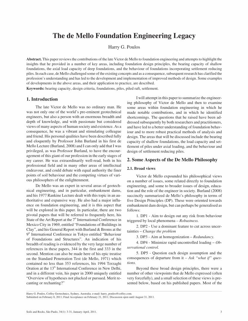
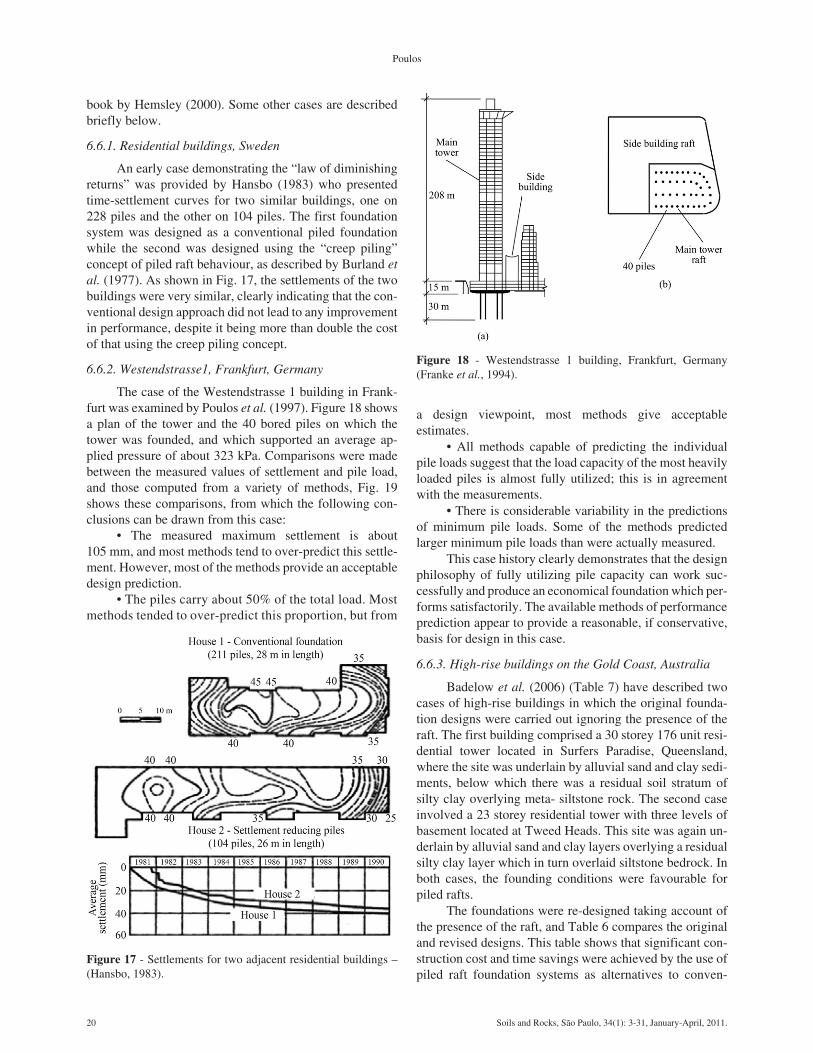
An early case demonstrating the “law of diminishingreturns” was provided by Hansbo (1983) who presentedtime-settlement curves for two similar buildings, one on228 piles and the other on 104 piles. The first foundationsystem was designed as a conventional piled foundationwhile the second was designed using the “creep piling”concept of piled raft behaviour, as described by Burland etal. (1977). As shown in Fig. 17, the settlements of the twobuildings were very similar, clearly indicating that the con-ventional design approach did not lead to any improvementin performance, despite it being more than double the costof that using the creep piling concept.
6.6.2. Westendstrasse1, Frankfurt, Germany
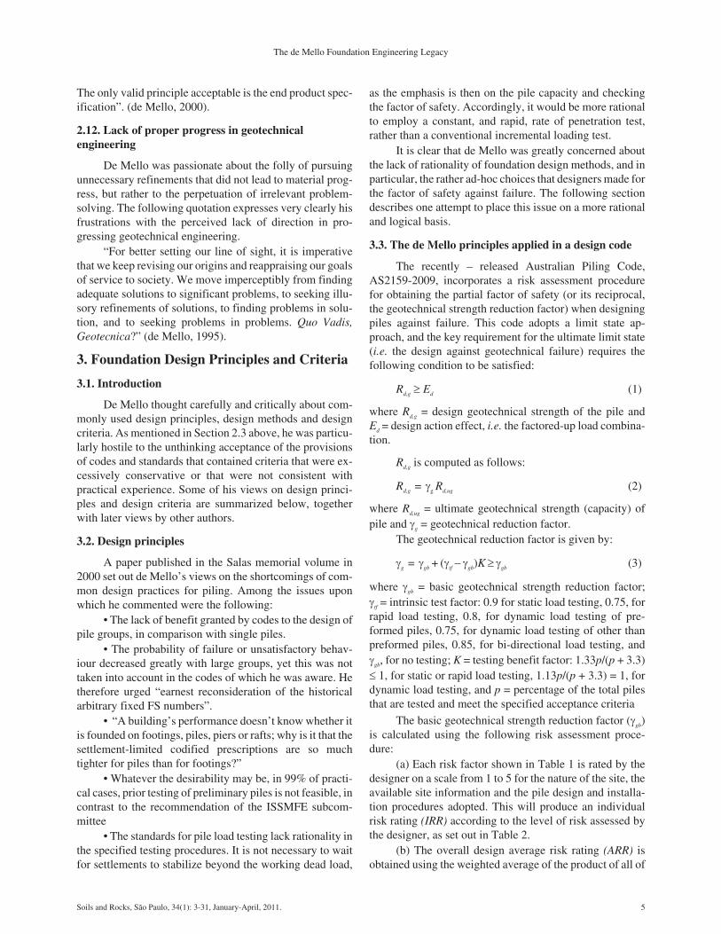
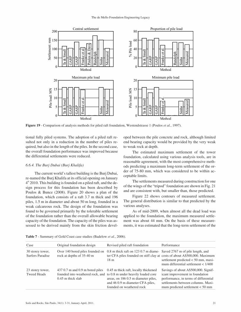
The case of the Westendstrasse 1 building in Frank-furt was examined by Poulos et al. (1997). Figure 18 showsa plan of the tower and the 40 bored piles on which thetower was founded, and which supported an average ap-plied pressure of about 323 kPa. Comparisons were madebetween the measured values of settlement and pile load,and those computed from a variety of methods, Fig. 19shows these comparisons, from which the following con-clusions can be drawn from this case:
• The measured maximum settlement is about105 mm, and most methods tend to over-predict this settle-ment. However, most of the methods provide an acceptabledesign prediction.
• The piles carry about 50% of the total load. Mostmethods tended to over-predict this proportion, but from
a design viewpoint, most methods give acceptableestimates.
• All methods capable of predicting the individualpile loads suggest that the load capacity of the most heavilyloaded piles is almost fully utilized; this is in agreementwith the measurements.
• There is considerable variability in the predictionsof minimum pile loads. Some of the methods predictedlarger minimum pile loads than were actually measured.
This case history clearly demonstrates that the designphilosophy of fully utilizing pile capacity can work suc-cessfully and produce an economical foundation which per-forms satisfactorily. The available methods of performanceprediction appear to provide a reasonable, if conservative,basis for design in this case.
6.6.3. High-rise buildings on the Gold Coast, Australia
Badelow et al. (2006) (Table 7) have described twocases of high-rise buildings in which the original founda-tion designs were carried out ignoring the presence of theraft. The first building comprised a 30 storey 176 unit resi-dential tower located in Surfers Paradise, Queensland,where the site was underlain by alluvial sand and clay sedi-ments, below which there was a residual soil stratum ofsilty clay overlying meta- siltstone rock. The second caseinvolved a 23 storey residential tower with three levels ofbasement located at Tweed Heads. This site was again un-derlain by alluvial sand and clay layers overlying a residualsilty clay layer which in turn overlaid siltstone bedrock. Inboth cases, the founding conditions were favourable forpiled rafts.
The foundations were re-designed taking account ofthe presence of the raft, and Table 6 compares the originaland revised designs. This table shows that significant con-struction cost and time savings were achieved by the use ofpiled raft foundation systems as alternatives to conven-
20 Soils and Rocks, São Paulo, 34(1): 3-31, January-April, 2011.
Poulos
Figure 17 - Settlements for two adjacent residential buildings –(Hansbo, 1983).
tional fully piled systems. The adoption of a piled raft re-sulted not only in a reduction in the number of piles re-quired, but also in the length of the piles. In the second case,the overall foundation performance was improved becausethe differential settlements were reduced.
6.6.4. The Burj Dubai (Burj Khalifa)
The current world’s tallest building is the Burj Dubai,re-named the Burj Khalifa at its official opening on January4th 2010. This building is founded on a piled raft, and the de-sign process for this foundation has been described byPoulos & Bunce (2008). Figure 20 shows a plan of thefoundation, which consists of a raft 3.7 m thick and 196piles, 1.5 m in diameter and about 50 m long, founded in aweak calcareous rock. The design of the foundation wasfound to be governed primarily by the tolerable settlementof the foundation rather than the overall allowable bearingcapacity of the foundation. The capacity of the piles was as-sessed to be derived mainly from the skin friction devel-
oped between the pile concrete and rock, although limitedend bearing capacity would be provided by the very weakto weak rock at depth.
The estimated maximum settlement of the towerfoundation, calculated using various analysis tools, are inreasonable agreement, with the most comprehensive meth-ods predicting a maximum long-term settlement of the or-der of 75-80 mm, which was considered to be within ac-ceptable limits.
The settlements measured during construction for oneof the wings of the “tripod” foundation are shown in Fig. 21and are consistent with, but smaller than, those predicted.
Figure 22 shows contours of measured settlement.The general distribution is similar to that predicted by thevarious analyses.
As of mid-2009, when almost all the dead load wasapplied to the foundation, the maximum measured settle-ment was about 44 mm. On the basis of these measure-ments, it was estimated that the long-term settlement of the
Soils and Rocks, São Paulo, 34(1): 3-31, January-April, 2011. 21
The de Mello Foundation Engineering Legacy
Figure 19 - Comparison of analysis methods for piled raft foundation, Westendstrasse 1 (Poulos et al., 1997).
Table 7 - Summary of Gold Coast case studies (Badelow et al., 2006).
Case Original foundation design Revised piled raft foundation Performance
30 storey tower,Surfers Paradise
Over 140 bored piles founded onrock at depths of 35-40 m
0.8 m thick raft on 123 0.7 m diame-ter CFA piles founded on stiff clay at18 m
Saved 2767 m of pile length, andcosts of about A$500,000. Maximumsettlement predicted < 50 mm, maxi-mum differential settlement < 1/400
23 storey tower,Tweed Heads
437 0.7 m and 0.9 m bored pilesfounded into weathered rock, and0.45 m thick slab
0.45 m thick raft, locally thickenedto 0.8 m under heavily loaded coreareas, on 186 0.5 m diameter piles,and 46 0.9 m diameter CFA piles,founded on weathered rock
Savings of about A$500,000. Signif-icant improvement in foundationperformance, in terms of differentialsettlements between columns. Maxi-mum predicted settlement < 50 mm
foundation would be of the order of 55 mm, somewhat lessthan the predicted 75 mm.
Overall, the performance of the piled raft foundationsystem has exceeded expectations to date.
6.6.5. Piled rafts on very soft soils
As mentioned earlier, soft clay sites do not provideideal ground conditions for piled rafts, but nevertheless, itis sometimes necessary to cope with such circumstances.As pointed out by Poulos (2005), possible foundation solu-tions may include:
• A compensated raft foundation;• A piled raft foundation;• A compensated raft foundation.Compensated piled rafts involve the excavation of
soil, before or after piles are installed, in order to reduce thenet increase in load applied by the foundation to the under-lying soft soil. The removal of soil reduces the verticaleffective stress in the soil, thus putting it in an over- consol-idated state and reducing its compressibility. The subse-quent loadings of the foundation will therefore tend tocause less settlement than if no excavation of the soil hadbeen carried out.
The key issues to be addressed in the design of com-pensated piled rafts are as follows:
• The maximum depth to which an excavation can becarried out.
• The effect of the overconsolidation caused by theexcavation on the stiffness and ultimate load capacity of theraft.
• The effect of the overconsolidation on the stiffnessand ultimate load capacity of the piles.
As a first approximation, it would appear reasonableto make the following assumptions with respect to raft be-haviour to allow for the possible effects of excavation:
• The modulus of the soil used to compute the raftstiffness is the unload/reload value until the average contactpressure below the raft reaches the “preconsolidation” pres-sure, i.e. the footing pressure required to cause virgin(first-time) loading of the footing to occur. For averagecontact pressures in excess of this “preconsolidation pres-sure”, the first loading modulus value is used.
• The ultimate bearing capacity of the raft is unaf-fected by the excavation process, other than for the effect ofembedment, which will tend to increase its capacity.
The possible effects of excavation on the soil modu-lus around the piles have been ignored, since the process ofpile installation generally causes a significant “preloading”of the soil around and below the pile shaft. Moreover, thesimplifying assumption is made that the ultimate axial ca-pacity of the piles is also unaffected by excavation.
6.6.6. Application to La Azteca building case
The case of the La Azteca building was described byZeevaert (1957) (Fig. 23). The building exerted a total aver-
22 Soils and Rocks, São Paulo, 34(1): 3-31, January-April, 2011.
Poulos
Figure 20 - Foundation layout for Burj Dubai.
Figure 21 - Measured and computed settlements – wing C.
Figure 22 - Measured settlement contours for the Burj Dubai(now the Burj Khalifa).
age loading of about 118 kPa, and was located on a deephighly compressible clay deposit which was also subjectedto ground surface subsidence arising from groundwater ex-traction. The building was founded on a compensated piledraft foundation, consisting of an excavation 6 m deep with araft supported by 83 concrete piles, 400 mm in diameter,driven to a depth of 24 m (i.e. the piles were about 18 mlong below the raft).
Figure 22 shows details of the foundation, the soilprofile, the settlement computed by Zeevaert, and the mea-sured settlements. The settlement without piles computedby Zeevaert (from a one-dimensional analysis) was sub-stantial, but the addition of the piles was predicted to reducethe settlement to less than half of the value without piles.The measured settlements were about 20% less than thecalculated settlements, but nevertheless confirmed the pre-dictions reasonably well.
An approximate analysis by the author was applied tothis case, excluding the effects of ground settlements,which were not detailed by Zeevaert in his paper. The fol-lowing approach was adopted:
1. The one dimensional compressibility data pre-sented by Zeevaert was used to obtain values of Young’smodulus of the soil at various depths, for the case of the softclays in a normally consolidated state. A drained Poisson’sratio of 0.4 was assumed. The modulus values thus ob-tained were typically very low, of the order of 0.5-1.0 MPa,and lower than would have been anticipated on the basis ofthe measured shear strength of the clay.
2. The bearing capacity of the raft was estimated fromthe shear strength data provided by Zeevaert, and wasfound to be about 200 kPa. This represented a factor ofsafety of about 1.7 on the average applied loading of118 kPa.
3. The settlement of an uncompensated raft was com-puted using these modulus values together with conven-tional elastic theory. A very large settlement, in excess of2.3 m, was obtained for the final settlement.
1. The settlement of a compensated raft was com-puted, assuming a 6 m depth of excavation, and assumingthat the soil modulus values for the overconsolidated statewere 10 times those for the normally consolidated state(based on the oedometer data presented by Zeevaert). Theadditional raft pressure to recommence virgin loading con-ditions, pec, was taken to be zero. A settlement of the orderof 988 mm was thus computed.
2. From the pile load tests reported by Zeevaert, val-ues of the single pile capacity and stiffness were obtained,these being about 735 kN and 25 MN/m respectively.
3. For the 83 piles used in the foundation, the groupstiffness was computed by using the approximation ofPoulos (1989) and applying a factor of 9.1 (the square rootof the number of piles, i.e. 830.5) to the single pile stiffness.A group stiffness of about 230 MN/m was calculated.
4. The average settlement of the foundation for an un-compensated piled raft was computed, using the equationsdeveloped by Randolph (1994) for the piled raft stiffness. Asettlement of about 1.08 m was obtained. The analysis indi-cated that, in this case, the raft would carry only about 4%of the load under elastic conditions, and that the capacity ofthe piles would be mobilized fully under the design load ofabout 78 MN.
5. The effects of carrying out a 6 m deep excavation(as was actually used) was simulated by reducing the thick-ness of the soil profile accordingly, and again assumingthat, for the raft, the soil Young’s modulus for the over-consolidated state was 10 times that for the normally con-solidated state (based on the laboratory oedometer datapublished by Zeevaert). The stiffness of the raft was thus in-
Soils and Rocks, São Paulo, 34(1): 3-31, January-April, 2011. 23
The de Mello Foundation Engineering Legacy
Figure 23 - Details of La Azteca building on compensated piled raft (Zeevaert, 1957).
creased significantly, leading also to a significant increasein the stiffness of the piled raft foundation, to about300 MN/m. The raft, at the design load, was found to carryabout 40% of the total load, and the computed settlementunder that load was reduced to about 280 mm.
The analysis results are summarized in Table 8. It canbe seen that the settlement of the compensated piled raft isabout 26% of the settlement of the piled raft without com-pensation, 29% of the settlement of the compensated raftalone, and only about 12% of the value for the uncompen-sated raft. Zeevaert’s calculations gave larger settlementsthan those computed above, being about 1000 mm for thecompensated raft alone, and about 370 mm for the compen-sated piled raft. This represented a reduction in settlementof about 63% in using the compensated piled raft ratherthan the compensated raft alone. This compares reasonablywell to the 71% reduction in settlement computed from thepresent approach. It is also interesting to note that the mea-sured settlements about 2 years after the commencement ofconstruction were about 20% less than those predicted byZeevaert. At that stage, the measured settlement was about205 mm and the computed settlement from Zeevaert was250 mm, i.e. about 68% of the final predicted settlement.Assuming a similar rate of settlement, the prediction madeby the author’s approach for the settlement after 2 yearswould be about 192 mm, in fair agreement with, but some-what less than, the measured 205 mm.
Clearly, the combined use of piles and compensationvia excavation, leads to a foundation that provides a supe-rior performance to that of an uncompensated piled raft or acompensated raft alone.
6.6.7. Piled raft cases in Malaysia
Tan et al. (2004, 2005) have described the applicationof conventional piled raft foundations to cases in Malaysiainvolving a series of 2-storey and 5-storey apartment build-ings founded on a relatively deep layer of soft silty clay.The soil profile consisted of 25-30 m of very soft to firmsilty clay with some intermediate sandy layers, underlainby silty sand. Figures 24 and 25 show the variation of com-pressibility and strength parameters with depth at the site.
The site was subjected to filling of 0.5 to 1 m in thick-ness, together with temporary surcharging having heightsvarying from 2 m to 5 m. After the subsoil had achieved aspecified percentage of settlement, the surcharging fills
were removed and construction of the foundation systemwas commenced.
For the 2-storey buildings, piled raft foundationswere used with relatively short friction piles of equallength. For the 5-storey buildings, piled rafts were alsoused, but the pile lengths were considerably longer and thepile length was varied, depending on the location.
24 Soils and Rocks, São Paulo, 34(1): 3-31, January-April, 2011.
Poulos
Table 8 - Summary of computed average settlements.
Case Computed average final settlement (mm) Ratio of settlement to settlement of compensated raft
Raft alone, no compensation 2342 2.37
Raft alone, with compensation 988 1.0
Piled raft, no compensation 1084 1.10
Piled raft, with compensation 283 0.29
Figure 24 - Compressibility parameters for Klang clay (Tan et al.,2004, 2005).
Figure 25 - Undrained strength and sensitivity of Klang clay (Tanet al., 2004, 2005).
In their analysis of the foundation systems, Tan et al.used a combination of techniques to estimate the overallsettlement behaviour and the pile-soil interaction. Theoverall settlement behaviour was computed from the con-ventional Terzaghi one-dimensional settlement analysiswhile the pile-soil interaction analysis involved iterativeapplication of a simplified pile group analysis based on thework of Randolph & Wroth (1979), together with a com-mercially available finite element analysis of the raft slab.
2-Storey BuildingsFor the 2-storey buildings, the column loads ranged
from 10 kN to 360 kN, and the line loadings from the brickwalls were from 9 kN/m to 16 kN/m. A uniform live load-ing of 2.5 to 3.0 kN/m2 was assumed to act over the groundfloor raft.
The foundation system consisted of a 150 mm thickraft slab thickened to a total of 600 mm over strips 350 mmwide below the column locations. 150 mm square rein-forced concrete piles, 9 m long, were located below the col-umns (Fig. 26).
Settlements were monitored over a 6-month period,from the completion of construction of the ground floorcolumns to the commencement of installation of the archi-tectural finishes. Figure 27 shows typical time-settlementrelationships for one of the buildings. During the observa-
tion period, the settlements increased relatively rapidlywith time, due to the increasing loads applied during con-struction, and at the end of the observation period, the max-imum settlement was about 17 mm, with a maximum angu-lar distortion of only 1/2850.
5-Storey buildingsFor the 5-storey buildings, the column loadings
ranged from 100 to 750 kN, and the line load from the brickwalls was 9 kN/m. A uniform live loading of 2.7 kPa wasassumed for the ground floor. The primary design criterionwas to limit the angular distortion to a maximum of 1/350 toprevent cracking in walls and partitions.
The foundation system developed consisted of a300 mm thick raft with thickened strips 350 mm wide by700 mm deep, supported by 200 mm square section rein-forced concrete piles with lengths varying from 18 m to24 m. The longer piles were located below the central por-tion of the buildings, as shown in Fig. 28. In this case, thedesigners followed the principle set out by Reul & Ran-dolph (2004) of reducing the differential settlements byconcentrating the stiffness provided by the piles towardsthe centre of a loaded area.
Settlements were monitored at various locations overa 10 month period from when the building had reached the3rd floor to more than 6 months after completion of thebuilding. Figure 29 shows the measured time-settlementbehaviour of the various locations. These measurements re-vealed that, while the observed settlements were relativelylarge, the maximum angular distortions over the period ofmeasurement were of the order of 1/1000.
Soils and Rocks, São Paulo, 34(1): 3-31, January-April, 2011. 25
The de Mello Foundation Engineering Legacy
Figure 26 - Typical column and pile layout for 2-storey building(Tan et al., 2004, 2005).
Figure 27 - Time-settlement monitoring results for typical 2-sto-rey block (Tan et al., 2004, 2005).
Analysis of Malaysian Cases
The Malaysian cases have been analysed using a sim-plified analysis for pile rafts (Poulos, 20001). On the basisof the available information, the following assumptionshave been made in the analyses:
1. The undrained shear strength su of the clay in-creases linearly with depth, according to the relationshipsu = 16 +1.6z kPa, where z = depth below ground surface inmetres.
2. The thickness of the soft compressible clay is 30 m.
3. The long-term drained Young’s modulus for theclay = 100su for calculating the settlement the raft and 200su
for the calculation of pile settlements.
4. The average loading applied to the foundation bythe buildings is 25 kPa for the 2-storey buildings and62.5 kPa for the 5-storey buildings (i.e. 12.5 kPa perstorey).
5. The raft for the 2-storey buildings is rectangular,with dimensions 80 m by 15 m.
6. The raft for the 5-storey buildings is rectangular,with dimensions 75 m by 25 m.
7. The settlement ratio for the pile groups, Rs, is ap-proximated as n0.5, where n = number of piles (Poulos,1989).
8. Interaction among adjacent blocks is ignored.Table 9 summarizes the results of the calculations for
the average settlement of each building when supported bythe piled raft system actually used. Also shown in this tableare the settlement computed for a raft without piles, and thesettlement computed if no account is taken of the presenceof the raft. It can be seen that the use of piles in conjunctionwith the raft has resulted in a substantial reduction in thesettlement, by a factor of about 3, as compared to the case ofthe raft alone, and by about 30%-40% compared to the pileswithout the raft.
Table 9 also shows the range of measured settlementreported by Tan et al. (2004, 2005) at the end of the settle-ment observation periods. The computed settlements forthe piled raft are of a similar order to those measured, bear-ing in mind that the measured settlements were still increas-ing significantly with time when the observations ceased.The cases reported by Tan et al. therefore clearly demon-strate the feasibility of employing piled raft systems to sup-port structures on soft clays.
6.7. Summary
The concept of settlement reducing piles, advocatedby Burland et al. (1977) has become recognized as a poten-tially economical and effective type of foundation whichhas been used successfully in a variety of ground condi-
26 Soils and Rocks, São Paulo, 34(1): 3-31, January-April, 2011.
Poulos
Figure 28 - Foundation system for 5-storey blocks with variablepile lengths.
Figure 29 - Time-settlement measurements for 5-storey blocks.
Table 9 - Summary of computed and measured settlements for buildings in Malaysia.
Case Settlement mm
2-storey buildings 5-storey buildings
Calculated final average settlement for raft without piles 128 329
Calculated final average settlement for piles without raft 63 132
Calculated final average settlement for piles with raft 43 99
Range of measured settlements at end of monitoring period 8-22 50-78
tions. It is not uncommon for savings in the cost of the foun-dations of about 30% to be achieved by using piled raftsinstead of conventional fully piled solutions.
Several of the world’s tallest buildings in the MiddleEast are founded on this type of foundation, while manybuildings in Frankfurt have functioned successfully onpiled rafts, despite the fact that total settlements in excess of100 mm have occurred. Piled rafts are most effective whenthe ground conditions near the underside of the raft are fa-vourable and allow the raft to develop considerable stiff-ness and bearing capacity. However, in recent years, theyhave also found application in very soft clays. The cases inMalaysia demonstrate that low-to-medium rise buildingson very soft clays can be supported by piled raft founda-tions in which the raft is relatively thin, and the piles are en-gineered to obtain acceptable settlement and differentialsettlement performance.
Compensated piled raft foundations can be an effec-tive foundation solution for very soft soils and have beenused successfully in Mexico City. They combine the reliefof overburden stress as a result of excavation, with the addi-tional capacity and stiffness that can be provided by com-bining piles with a mat or raft foundation.
7. Conclusions
Victor de Mello developed a philosophy of founda-tion design that incorporated both common sense andsound theory. He questioned a number of conventional de-sign approaches and pointed out their shortcomings. In par-ticular, he was highly critical of codes that were poorlyconceived and inflexible, and that led to uneconomical de-signs. The shortcomings that he identified in design meth-ods included the following:
1. The use of traditional bearing capacity theory to es-timate the ultimate load capacity of shallow foundations.Subsequent research has found that the traditional rigidplastic theory can be unconservative in that the effects ofsoil compressibility can reduce the bearing capacity verymarkedly, and that the theoretical size effect for founda-tions on sand (in which larger footings can develop largerbearing capacities) is not borne out in practice. However,on the positive side, the simple procedures adopted in prac-tice to handle eccentric loading and applied moment appearto have been verified by subsequent research using sophis-ticated three-dimensional numerical analysis.
2. The commonly used “� method” for estimating theultimate shaft friction of piles in clay is not always reliable.While considerable research has been carried out since1969 to improve our ability to predict pile capacity andload-settlement behaviour, the accurate prediction of axialpile capacity remains rather elusive, despite the increasedunderstanding of pile-soil interaction and the increased so-phistication of some of the more recent methods of calcula-tion. While some success has been achieved in predictingthe load-settlement behaviour of single piles, accurate pre-
diction of the settlement of pile groups, particularly if thepiles are floating, also remains elusive. Given the high de-gree of sophistication that it is now possible to bring to bearon pile prediction tasks, it appears likely that the lack ofconsistent success may be due more to the deficiencies incharacterising the ground profile, than to deficiencies in themethods of calculation.
3. The concept of settlement reducing piles, advo-cated by Burland et al. (1977) has become recognized as apotentially economical and effective type of foundationwhich has been used successfully in a variety of groundconditions. It is not uncommon for savings in the cost of thefoundations of about 30% to be achieved by using piledrafts instead of conventional fully piled solutions. There isalso potential for a compensated piled raft foundation to re-duce both the absolute settlement and the differential settle-ment between the foundation and the surrounding soft soil.It therefore provides a means of developing a foundationthat works and settles “with the ground”, rather than onewhich “fights the ground”.
It is sobering to reflect on the almost despairing ques-tion asked by de Mello in 1995 “Quo vadis, Geotecnica?” Itmay be argued that our capacity to solve numerical and ana-lytical problems in geotechnical engineering has developedenormously in the 15 years since he asked that question.Yet, it may also be argued that our ability to make realisticpredictions of foundation performance has barely im-proved. This lack of progress may be attributed to a numberof factors, but perhaps the most pertinent of these are:
1. The enduring difficulty of carrying out adequateground investigations to properly characterise a site. De-spite the ground conditions often being the most potent riskfactor in an engineering project, ground investigation is stillgenerally treated as a commodity to be obtained at thecheapest price, rather than as a vital component of the engi-neering design process.
2. The difficulty of quantifying the soil and rock prop-erties, taking into account the multitude of geological, envi-ronmental and geotechnical features that influence theground behaviour. There is likely to be an optimal level ofcharacterization that can be sought, perhaps analogous tothe story of Goldilocks and the three bears. There can be toolittle effort expended (“the porridge is too cold”) and so keyaspects of behaviour are overlooked or not described ade-quately. There can be too much effort expended (“the por-ridge is too hot”), in which enormous effort is expended onevery conceivable type of in-situ and laboratory test, andthen tries to incorporate every conceivable physical phe-nomenon into the ground model. In such cases, the transla-tion of the results into a practical ground model is either toolengthy or else it may still miss the key features of the prob-lem. Then there is the optimal solution (“the porridge is justright”) in which experience and judgement are combinedwith sound in-situ and laboratory testing to produce an ade-quate ground model that suits the key features of the prob-
Soils and Rocks, São Paulo, 34(1): 3-31, January-April, 2011. 27
The de Mello Foundation Engineering Legacy
lem, without trying to cover irrelevant aspects of behav-iour.
3. The enduring difficulty of honestly evaluating ourability to do “Class A” predictions. De Mello commentedon, and despaired of, the lack of success of experts in pre-diction events. It would no doubt be gratifying to him ifthere was a concerted effort made to make performancemeasurements and comparisons between anticipated andmeasured behaviour, a routine part of the construction andoperation process.
4. Perhaps because of the increasingly large numberof geotechnical researchers and the current publishing im-perative, much of the geotechnical research is directed to-wards what may be termed “the last 2%” of a problem, i.e.the refinement of analyses and design procedures that aremore than adequate for practical purposes. What is neededfar more in research is another concerted effort to close thegap between theory and practice and to identify what com-binations of ground investigation quantification and designmethod give reliable outcomes. It may well be time to heedde Mello’s pleas and discard some of the old traditional the-ories (for example, the Terzaghi bearing capacity theory)and to stop the perpetuation of teaching of such theoriessimply because they appear in text books that have beenwritten without an adequately critical appraisal of their ap-plicability to geotechnical reality.
It would be highly instructive for students to be di-rected back to the writings of such giants of the professionas Terzaghi, Casagrande, Taylor, Skempton and de Mello.There they would find a great deal of wisdom and guidancethat would assist them in understanding what is significantin a geotechnical problem and what is not. Then, in combi-nation with properly digested and calibrated modern theo-ries and design methods, they could achieve improvedcapabilities in designing foundation according to the 5 de-sign principles of de Mello set out in Section 2.
It may be appropriate to conclude by appreciating thebroader legacy that Victor de Mello left to our professionand recalling the following words from his Presidential ad-dress at the 1985 International Conference in San Fran-cisco:
“Engineering uses art and science, intuition, and ofcourse, the rational analyses of the day: all these are means.But the end is creativity, often inventiveness, ingenious.Engineering is the end product of design + construction +operation, a live function to be continually reviewed and re-vised in order to preserve or enhance the intent. As a com-munity of engineers, we must urgently repel the widespreadnotion of our acting on certainty, and providing static, per-manently valid projects”.
Acknowledgments
I am grateful to Prof. John Small for reviewing thispaper, and am indebted to many of my colleagues overmany years for their support and advice, both in academia
and consulting practice. Perhaps above all, three personshave had a major influence on my career: the late ProfessorE.H. Davis, who was my mentor, colleague and friend dur-ing the early part of my career, Professor T. William Lam-be, who gave me the opportunity to become involved in theprediction of the performance of foundations and embank-ments, and the Late Professor Victor de Mello, who was anearly supporter of my research and who subsequently pro-vided continual support, advice and stimulation.
ReferencesAltaee, A.; Evgin, E. & Fellenius, B.H. (1993) Axial load
transfer for piles in sand. III: Load transfer for piles insand and the critical depth. Canadian GeotechnicalJournal, v. 30:3, p. 455-463.
Akbas, S.O. & Kulhawy, F.H. (2009) Axial compression offootings in cohesionless soils. II: Bearing capacity. Jnl.Geot. & Geoenv. Eng., ASCE, v. 135:11, p. 1575-1582.
Aoki, N. & Velloso, D.A. (1975) An approximate methodto estimate the bearing capacity of piles. Proc. 5th PanAmerican Conf. Soil Mechs. Found. Eng., Buenos Ai-res, pp. 367-376.
Badelow, F.; Poulos, H.G.; Small, J.C. & Moyes, P. (2006)Economic foundation design for tall buildings. Proc.10th Int. Conf. Piling and Deep Founds., Amsterdam,DFI, pp. 200-209.
BCP Committee (1971) Field tests on piles in sand. Soilsand Founds, v. 11:2, p. 29.
Burland, J.B. (2008) Reflections on Victor de Mello, frien-d, engineer and philosopher. Soils and Rocks, v. 31:3,p. 111-123.
Burland, J.B.; Broms, B.B. & De Mello, V.F.B. (1977) Be-haviour of foundations and structures. Proc. 7th Int.Conf. Soil Mechs. Found. Eng., Tokyo, v. 1, pp. 495-548.
Burland, J.B. & Wroth, C.P. (1974) Settlement of buildingsand associated damage. In: Settlement of Structures.Pentech Press, London, pp. 611-654.
Burland, J.B. & Burbridge, M.C. (1985) Settlements offoundations on sand and gravel. Proc. I.C.E., v. 1,pp. 1325-1381.
Bustamante, M. & Gianeselli, L. (1982) Pile bearing capac-ity prediction by means of static penetrometer CPT.Proc. ESOPT II, Amsterdam, v. 2, pp. 492-500.
Carter, J.P.; Randolph, M.F. & Wroth, C.P. (1979b) Stressand pore pressure changes in clay during and after theexpansion of a cylindrical cavity. Int. J. Num. and Anal.Methods in Geomechanics, 3: 305-322.
Clausen, C.J.F.; Aas, P.M. & Karlsrud, K. (2005) Bearingcapacity of driven piles in sand, the NGI approach.Proc. 1st Int. Symp. On Frontiers in Offshore Geo-technics, Perth, Balkema, pp. 677-681.
Coyle, H.M. & Reese, L.C. (1966) Load transfer for axiallyloaded piles in clay. Jnl. Soil Mechs. Founds. Divn.,ASCE, 92:SM2, p. 1-26.
28 Soils and Rocks, São Paulo, 34(1): 3-31, January-April, 2011.
Poulos
Davis, E.H. & Booker, J.R. (1971) The bearing capacity ofstrip footings from the standpoint of plasticity theory.Proc. First Australia-New Zealand Conference on Geo-mechanics, v. 1, pp. 276-282.
Decourt, L. (2008) Loading tests: interpretation and predic-tion of their results. Geot. Spec. Pub. No. 180, J.E. Laieret al. (ed), ASCE, pp. 452-470.
Deeks, A.D.; White, D.J. & Bolton, M.D. (2005) A com-parison of jacked, driven and bored piles in sand. Proc.16th Int. Conf. Soil Mechs. Geot. Eng., Osaka.
De Mello, V.F.B. (1969) Foundations of buildings in clay.State-of-the art report, Proc. 7th Int. Conf. Soil Mechs.Found. Eng., Mexico City, SOA Volume, pp. 49-136.
De Mello, V.F.B. (1971) The standard penetration test.Proc. 4th Pan American Conf. Soil Mechs. Found. Eng.,San Juan Puerto Rico, ASCE, v. 1, pp. 1-86.
De Mello, V.F.B. (1972) Thoughts on soil engineering ap-plicable to residual soils. Proc. 3rd SouthEast AsianConf. On Soil Eng., Hong Kong, pp. 5-34.
De Mello, V.F.B. (1983) Present criteria for design andconstruction of high-capacity piles. Conf. 25 Anniv.Soc. Venezolana de Mech. Del Suelo e Ing. de Funda-ciones, Caracas, pp. 107-127.
De Mello, V.F.B. (1984) Design decisions, design calcula-tions and behaviour prediction computations; referredto statistics and probabilities. Proc. 6th Danube Conf.Soil Mechs. Found. Eng., Budapest, Ed. G. Petrasovits,pp. 37-44.
De Mello, V.F.B. (1992) Revisiting conventional geotech-nique after 70 years. US/Brazil Geot. Workshop on Ap-plicability of Classical Soil Mechanics Principles toStructured Soils, pp. 22-61.
De Mello, V.F.B. (1994) Revisiting our origins. In: Ter-zaghi Oration. Proc. 13th Int. Conf. Soil Mechs. Found.Eng., New Delhi, pp. 13-34.
De Mello, V.F.B. (1995) Revisitations on sample founda-tion designs. Solos e Rochas, v. 18:2, p. 75-92.
De Mello, V.F.B. (2000a) Reflections on needed logicalunifying of basic geotechnical prescriptions: simple ex-amples. Libro Homenaje a Jose Antonio Jiminez Salas,Geotecnia en al ano 2000, CEDEX, pp. 7-16.
De Mello, V.F.B. (2000b) Overview of hypotheses notplucked or pursued. Merit recanting or chanting? Geo-tech. Year 2000, Developments in Geot. Eng., Bang-kok, pp. 355-372.
Fadaee, M.J. & Rowhani, M. (2006) Optimization of piledraft foundations using generic algorithm and neural net-works. 10th East Asia Pacific Conf. on Struct. Eng. andConstrn., Bangkok.
Fellenius, B. & Altaee, A.A. (1994) Critical depth: how itcame into being and why it does not exist. Proc. Instn.Civ. Engrs., Geot. Eng., v. 113:April, p. 107-111.
Fleming, W.G.K.; Weltman, A.J. & Randolph, M.F. (1992)Piling Engineering. 2nd ed, Halsted Press, New York.
Foye, K.C.; Abou-Jaoude, G.; Prezzi, M. & Salgado, R.(2009) Resistance factors for use in load and resistancefactor design of driven pipe piles in sands. Jnl. Geot.Geoenv. Eng., ASCE, v. 135:1, p. 1-13.
Franke, E.; Lutz, B. & El-Mossalamy, Y. (1994) Measure-ments and numerical modelling of high-rise buildingson Frankfurt clay. ASCE Spec. Pub. v. 40:2, p. 1325-1336.
Gavin, K.; Adekunte, A. & O’Kelly, B. (2009) A field in-vestigation of vertical footing response on sand. Geo-technical Eng., ICE, v. 162:GE5, p. 257-267.
Hansbo, S. & Källström, R. (1983) A case study of two al-ternative foundation principles. Väg-och Vattenbyg-garen v. 7-8, p. 23-27.
Horikoshi, K. & Randolph, M.F. (1998) A contribution tothe optimum design of piled rafts. Geotechnique,v. 48:2, p. 301-317.
Jardine, R.J. & Chow, F. (1996) New design methods foroffshore piles. MTD Pub. 96/103, Marine TechnologyDirectorate, London.
Jardine, R.J.; Chow, F.; Overy, R. & Standing, J. (2005) CPdesign methods for driven piles in sand and clays.Thomas Telford, London.
Karlsrud, K.; Clausen, C.J.F. & Aas, P.M. (2005) Designcriteria for pipe piles in clay, the NGI approach. Proc. 1st
Int. Symp. On Frontiers in Offshore Geotechnics, Bal-kema, Perth, Australia, pp. 677-681.
Katzenbach, R.; Arslan, U.; Moorman, C. & Reul, O.(1998) Piled raft foundations: interaction between pilesand raft. Darmstadt Geotechnics, Darmstadt Universityof Technology, v. 4, p. 279-296.
Kerisel, J. (1961) Fondations profondes en milieu sableux.Proc. 5th Int. Conf. Soil Mechs. Found. Eng., Paris, v. 2,p. 73-83.
Kerisel, J. (1965) Vertical and horizontal bearing capacityof deep foundations in clay. Proc. Symp. On BearingCapacity and Settlement of Foundations, Duke Univer-sity, Durham, NC, pp. 45-52.
Kolk, H.J.; Baaijens, A.E. & Senders, M. (2005) Designcriteria for pipe piles in silica sands. Proc. 1st Int. Symp.On Frontiers in Offshore Geotechnics, Balkema, Perth,Australia, pp. 711-716.
Lam, T.S.K. & Johnston, I.W. (1982) A Constant normalstiffness direct shear machine. Proc. 7th S.E. AsianConf. on Soil Eng., Hong Kong, pp. 805-820.
Lehane, B.M.; Schnieder, J.A. & Xu, X. (2005) TheUWA-05 method for prediction of axial capacity ofdriven piles in sand. 1st Int. Symp. On Frontiers in Off-shore Geotechnics, Balkema, Perth, Australia, pp. 683-689.
Kraft, L.M.; Kagawa, T. & Ray, R.P. (1981) Theoretical t-zcurves. Jnl. Geot. Eng., ASCE, 107:11, p. 1543-1561
Soils and Rocks, São Paulo, 34(1): 3-31, January-April, 2011. 29
The de Mello Foundation Engineering Legacy
Kulhawy, F.K. (1984) Limiting tip and side resistance: factor fallacy? Anal. and Des. of Pile Founds., J.R. Meyer,ed., ASCE, pp. 80-98.
Mandolini, A.; Russo, G. & Viggiani, C. (2005) Pile foun-dations: experimental investigations, analysis anddesign. Proc. 16th Int. Conf. Soil Mechs. Geot. Eng.,Osaka, Millpress, Rotterdam, v. 1, pp. 177-213.
Mayne, P.W. & Elhakim, A. (2002) Axial pile responseevaluation by geophysical piezocone tests, Proceed-ings, Ninth International Conference on Piling & DeepFoundations, DFI, Nice, Presses de l’ecole nationaledes Ponts et Chaussees, pp. 543-550.
Meyerhof, G.G. (1951) The ultimate bearing capacity offoundations, Géotechnique, v. 2, p. 301-332.
Meyerhof, G.G. (1953) The bearing capacity of founda-tions under eccentric and inclined loads. Proc. 3rd Int.Conf. Soil Mechanics and Foundation Engineering, Zu-rich, v. 1, pp. 440-445.
Meyerhof, G.G. 1976. Bearing capacity and settlement ofpile foundations. Jnl. Geot. Eng. Div., ASCE,v. 102:GT3, p. 195-228.
O’Neill, M.W. (2001) Side resistance in piles and drilledshafts. Int. Geot. and Geoenv. Eng., ASCE, v. 127:1,p. 3-16.
Ooi, L.H. & Carter, J.P. (1987) A constant normal stiffnessdirect shear device for static and cyclic loading. Geot.Testing Jnl., ASTM, v. 10, p. 3-12.
Poulos, H.G. (1993) Settlement of bored pile groups. Proc.BAP II, Ghent, Balkema, Rotterdam, pp. 103-117.
Poulos, H.G. (1994b) Settlement prediction for driven pilesand pile groups. Spec. Tech. Pub. v. 40:2, p. 1629-1649.
Poulos, H.G. (1989) Pile behaviour – Theory and applica-tion. 29th Rankine Lecture. Géotechnique, v. 39:3,p. 65-415.
Poulos, H.G. (2000) Pile-raft interaction – Alternative me-thods of analysis. Devels. in Theoretical Geomechs.,ed. D.W. Smith & J.P. Carter, Balkema, Rotterdam,pp. 445-463.
Poulos, H.G. (2001) Piled raft foundations – Design and ap-plications. Geotechnique, v. 51:2, p. 95-113.
Poulos, H.G. (2004) An approach for assessing geotech-nical reduction factors for pile design. Proc. 9th Austra-lia-New Zealand Conf. on Geomechanics, Auckland,v. 1, pp. 109-115.
Poulos, H.G. (2005) Pile behavior – Consequences of geo-logical and construction imperfections. 40th TerzaghiLecture, Jnl. Geot. & Geoenv. Eng., ASCE, v. 131:5,p. 538-563.
Poulos, H.G. (2006) Pile group settlement estimation – Re-search to practice. Keynote Paper, Foundation Analysis
and Design, Innovative Methods, ED. R.L. Parsons etal., ASCE GSP No. 153, pp. 1-22.
Poulos, H.G. & Bunce, G. (2008) Foundation design for theBurj Dubai – The world’s tallest building. Proc. 6th Int.Conf. Case Histories in Geot. Eng., Arlington, VA, Pa-per 1.47, CD-Rom.
Poulos, H.G.; Carter, J.P. & Small, J.C. (2002) Foundationsand retaining structures – Research and practice. Stateof the Art Lecture, Proc. 15th Int. Conf. Soil Mechs,Found. Eng., Istanbul, v. 4, pp. 2527-2606.
Poulos, H.G. & Chua, E.W. (1985) Bearing capacity offoundations on calcareous sand. Proc. 11th Int. Conf.Soil Mech. Found. Eng., San Francisco, v. 3, pp. 1619-1622.
Poulos, H.G. & Davids, A.J. (2005) Foundation design forthe Emirates Twin Towers, Dubai. Can. Geot. Jnl.,v. 42, p. 716-730.
Poulos, H.G. & Davis, E.H. (1968) The settlement behav-iour of single axially-loaded incompressible piles andpiers. Geotechnique, v. 18, p. 351-371.
Poulos, H.G. & Davis, E.H. (1980) Pile Foundation Analy-sis and Design. New York, John Wiley.
Poulos, H.G.; Small, J.C.; Ta, L.D.; Sinha, J. & L. Chen(1997) Comparison of some methods for analysis ofpiled rafts. Proc. 14th Int. Conf. Soil Mechs. Foundn.Eng. Hamburg, Balkema, Rotterdam, v. 2, pp. 1119-1124.
Randolph, M.F. (1994) Design methods for pile groups andpiled rafts. Proc. 13th Int. Conf. S.M. & Found. Eng.,v. 5, pp. 61-82.
Randolph, M.F. (2003) Science and empiricism in pilefoundation design. 43rd Rankine Lecture, Geotechnique,v. 53:10, p. 847-875.
Randolph, M.F.; Carter, J.P. & Wroth, C.P. (1979) Drivenpiles in clay – The effects of installation and subsequentconsolidation. Géotechnique, v. 29:4, p. 361-393.
Randolph, M.F. & Wroth, C.P. (1979) An analysis of thevertical deformation of pile groups. Géotechnique,v. 29:4, p. 423,439.
Reul, O. & Randolph, M.F. (2004) Design strategies forpiled rafts subjected to non-uniform vertical loading.Jnl. Geot. & Geoenv. Eng., ASCE, v. 130:1, p. 1-13.
Seed, H.B. & Reese, L.C. (1955) The action of soft clayalong friction piles. Proc. ASCE, 81, Paper 842.
Seo, H.; Yildrim, I.Z. & Prezzi, M. (2009) Assessment ofthe axial load response of an H pile driven in multilay-ered soil. Jnl. Geot. Geoenv. Eng., ASCE, v. 135:12,p. 1789-1804.
Sinha, J & Poulos, H.G. (1997) Piled raft foundation sys-tems in swelling and shrinking soils. Proc. 14th Int.Conf. Soil Mechs. Found. Eng., Hamburg, v. 2,pp. 1141-1144.
Skempton, A.W. & MacDonald D.H. (1956) The allowablesettlements of buildings. Proc. Instn. Civ. Engrs.,v. III:5, p. 727-768.
30 Soils and Rocks, São Paulo, 34(1): 3-31, January-April, 2011.
Poulos
Tabucanon, J.T.; Airey, D.W. & Poulos, H.G. (1995) Pileskin friction in sands from constant normal stiffnesstests. Geot. Testing Jnl., ASTM, v. 18:3, p. 350-364.
Taiebat H. & Carter J.P. (2000) Numerical studies of thebearing capacity of shallow footings on cohesive soilsubjected to combined loading. Géotechnique, 50:4,p. 409-18.
Tan, Y.C.; Chow, C.M. & Gue, S.S. (2004) A design ap-proach for piled raft with short friction piles for low risebuildings on very soft clay. Proc. 15th Southeast AsianGeot. Soc. Conf., Bangkok, v. 1, pp. 171-176.
Tan, Y.C.; Chow, C.M. & Gue, S.S. (2005) Piled raft withdifferent pile length for medium-rise buildings on verysoft clay. Proc. 16th Int. Conf. Soil Mechs. Found. Eng.,Osaka, v. 3, pp. 2045-2048.
Terzaghi, K. (1943) Theoretical soil mechanics. John Wil-ley, New York.
Vesic, A.S. (1969) Experiments with instrumented pilegroups in sand. ASTM, STP v. 444, pp. 177-222.
Vesic, A.S. (1973) Analysis of ultimate loads of shallowfoundations, Jnl Soil Mechanics and Foundation Divi-sion, ASCE, v. 99, p. 45-73.
Zeevaert, L. (1957) Compensated friction pile foundationto reduce settlement of buildings on the highly com-pressible volcanic clay of Mexico City. Proc. 4th Int.Conf. SMFE, London, v. 2, pp. 81-86.
Zhang, L. & Ng, A.M.Y. (2006) Limiting tolerable settle-ment and angular distortion for building foundations.Probabilistic Applications in Geotechnical Engine-ering, GSP 170, ASCE (CD-Rom).
Soils and Rocks, São Paulo, 34(1): 3-31, January-April, 2011. 31