THE DEMONSTRATION OF AN ADVANCED CYCLONE COAL COMSUSTOR, WITH INTERNAL SULFUR, NITROGEN, AND ASH CONTROL FOR THE CONVERSION OF A 23 MMBTUlHOUR OIL FIRED BOILER TO PULVERIZED COAL Final Technlcal Repon lor the Period March 9.1987-February 28.1991 BY Bert Zauderer Edward S. Fleming Augusl30,lSSl Work Performed Under Contract No. FC22-97PC79799 For U.S. Departmen of Energy Pittsburgh Energy Technology Center Pittsburgh, Pennsylvanla BY Coal Tech Corporation Marlon, Pennsylvsnla REPRODUCED SY U.S. DEPARTMENT OF COMMERCE NA’IIONN. lEOHNkXL INFORMATION SERVICE SPRiNQFELD. VA %YSl
Transcript
THE DEMONSTRATION OF AN ADVANCED CYCLONE COAL COMSUSTOR, WITH INTERNAL SULFUR, NITROGEN, AND ASH CONTROL FOR THE CONVERSION OF A 23 MMBTUlHOUR OIL FIRED BOILER TO PULVERIZED COAL
Final Technlcal Repon lor the Period March 9.1987-February 28.1991
BY Bert Zauderer Edward S. Fleming
Augusl30,lSSl
Work Performed Under Contract No. FC22-97PC79799
For U.S. Departmen of Energy Pittsburgh Energy Technology Center Pittsburgh, Pennsylvanla
BY Coal Tech Corporation Marlon, Pennsylvsnla
REPRODUCED SY U.S. DEPARTMENT OF COMMERCE
NA’IIONN. lEOHNkXL INFORMATION SERVICE SPRiNQFELD. VA %YSl
DISCLAIMER
This repon wac prq!ard as an acu~unl of Work sponsored by an agency of the United Stars Government. Neither the United Stata Govcmment nor any agency IIuMI, nor any of their employees. makes any warranty, exprcs or implied, or assumes my legal liability or mponrihilily for the accuracy. wmpktepess. or usefulness of any’iniormation, app.waW product, or pmcus discllosed. 01 repisens that its use would not infringe privately owned rights. Refewa bettin to any specific commercial prcduct, prccts. or wrvia by trade name. tmdcmark, manufacturer, or otherwise does not nuxswily conrdrure or imply ifs cndorscmnt. recommendation, or iavming by the United States Govcmmcnr or any agency thereof. The views and opinions of authors cx. prcstd herein do nor -rily state or reflect thav of the United Staw.~Govemmcnt or any agency. there&
This report has been reproduced directly from the beat available copy.
Available to DOE and DOE contractors from the Office of Scientific and Technical Information, P.O. Box 62, Oak Ridge, TN 37831; prices available from (615)576~8401, FlB 626-8401..
Available to the public froin the National Technical Information Service, U.S. Department of Commerce, 5285 Port Royal Rd., Springfield, VA 22161.
DOElPCl79799-T7 (DE92002597J
Dirnib”dcm megor*, “c-102 a--d UC.104
U.S. lX)E-CLEAN COAL FRGRAM
"JTIE DE$KNSTRATICYN OF AN ADVANCED CYCLONE COAL CmlBUSTCm. WITH INTERNAL SOLFLR, NITRCT;GN, AND ASH CONTBOL FOR THE CORJERSICN OF A 23 MMBl'U/HOLJR
OIL FIRED BOILER TO PULVERIZED COAL"
FINAL TECHNICAL RERXI'
REXRTIffi PERIOD - March 9..1987 to February 28, 1991 DOE Cooperative Agreement No. DE-FC22-87FC79799
3.3.4.2. Environmental Performance .,,': 3.3.4.2.1: "Ox Control ~,
3.3.4.2.2. SO2 Control 3.3.4.'2.3. Slag Reactivity 3.3.4.2.4. Particulates 3.3.4.2.5. ,Wastswater
3.3.4.3. Impact on Combustor Design and Operation 3.3.5. Summary of Accomplishments
3.4. Recommendations ,for Future Work 3.4.1. Near-Term
3.4.1.1. Sulfur Capture Tests in Comtustor 3.4.1.2..Round-the-Clock Coal Fired Operation
3.4.2. Long-Term 3.5. Combtor Applications
,3.5.1: Boiler Retrofit Applications 3.5.2. Solid Waste Control Applications 3.5.31 Economics of Retrofit of a.250 MWe Power Plant.
APPENDIX I. Chronological Description of Tests APPENDIX II. Statistical Analysis of Com~tor Operating Data A?'PFNDIX III.Pho~aphic History of the Project APPKNDIX IV. Hodule~l-Slag Chemical Test Results APPBDIX V. Properties of Test C&ls and Sorb&x Ck$e: Appendices contain ,their own table of.contents) :
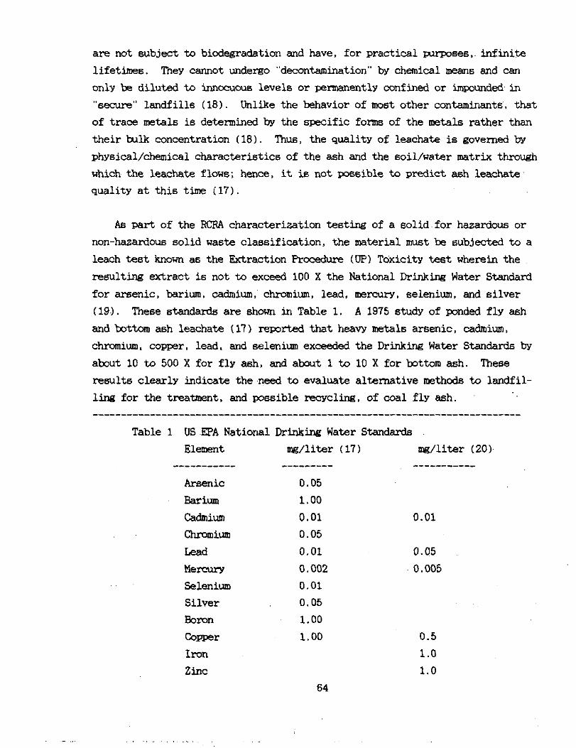
LIST OF TABLES Table 1. US EPA National Drinkti ~ Water Standad’ 64 Table 2. Leaoh Test Results for Parent Fly Ash and
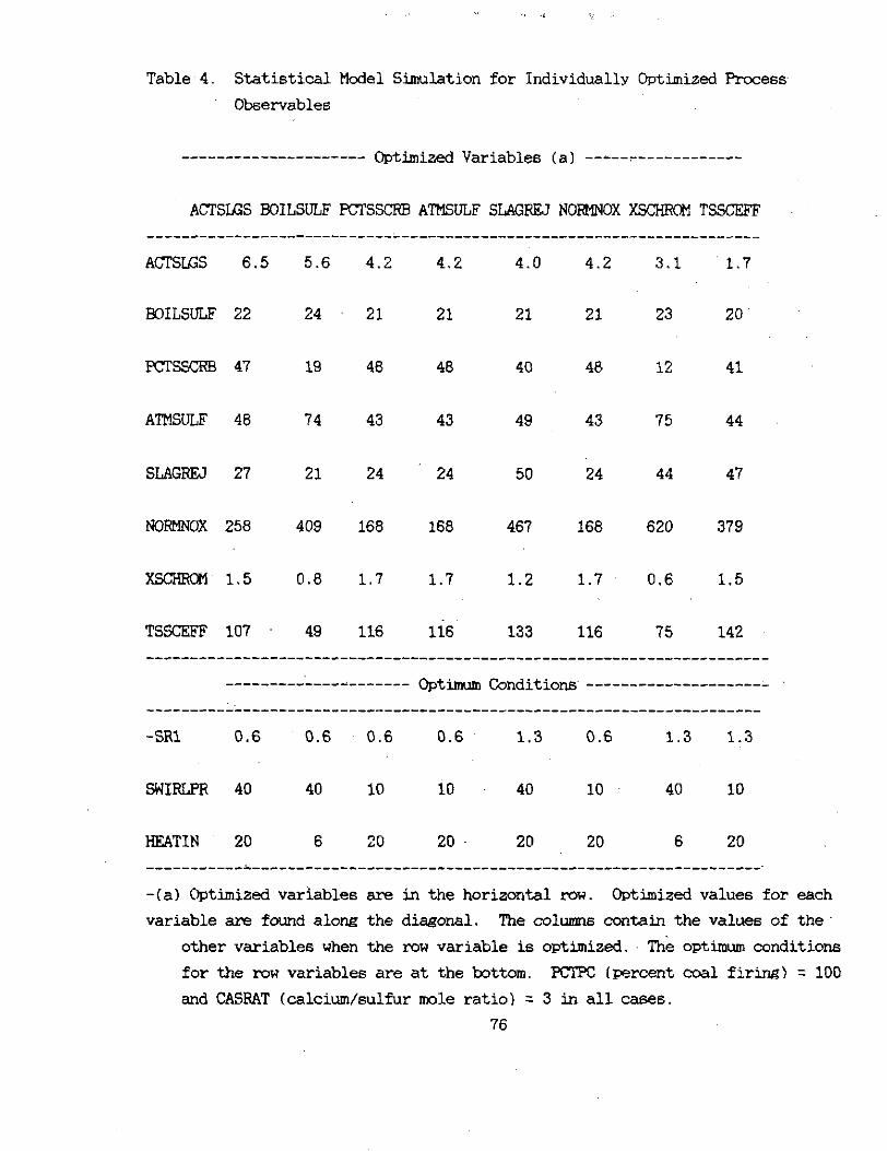
Resultant Slag from Test EPA1 66 Table 3. Metal Content of Parent Fly Ash 81 Resultant Slag fm Teat EPA1 67 Table 4. Statistical Model Simulation for Individtilly Optimised PlPcaes
Variables F 76
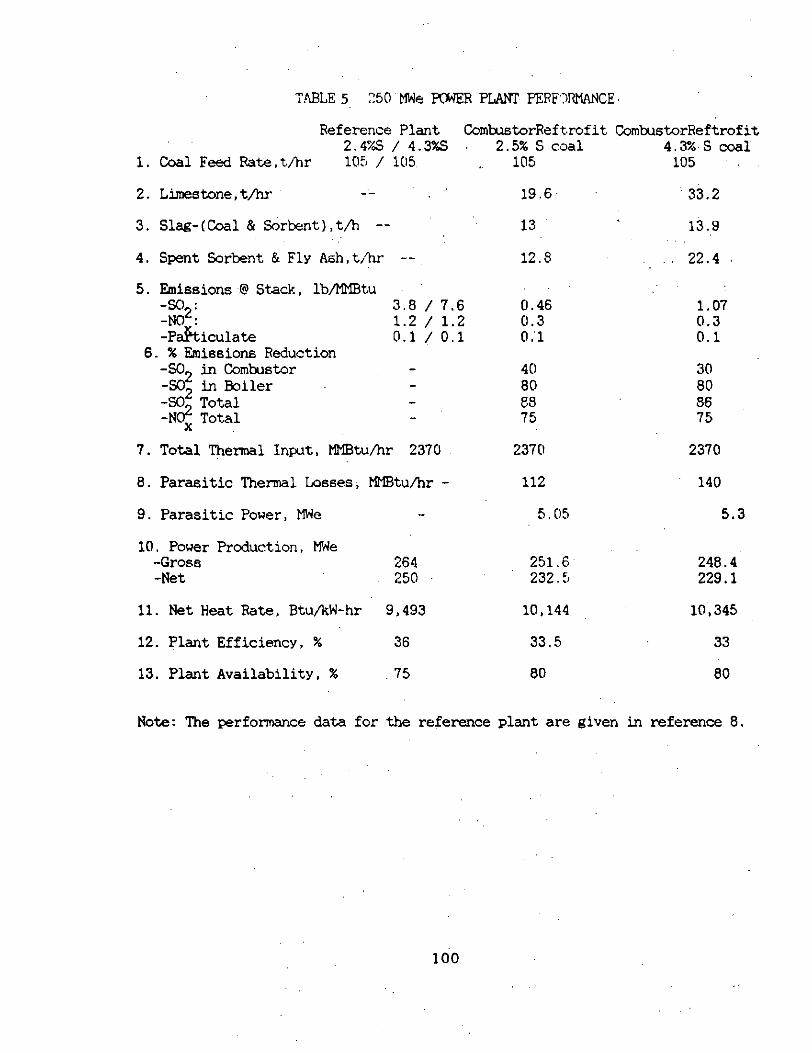
Table 5 -Perfonmnce & So2 Control in a 250 Mwe Plant Retmfitted with Coal Tech'6 Co&u&or
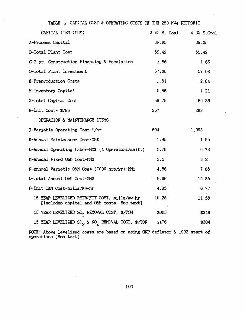
Table 6 -Capital and o&M Costs of a 250 MWe Retrofit 100 101
LIST OF FIG- Schematic Diagram of Coal Tech's Advanced Air Cooled Cyclme CcalComLu3tor. 102 Tampslla/Keeler Boilerhouse. 103 Side View of the Co&u&m Attached to the Boiler. 104 Plot Plan of the Installation. 105 Process Flow Block Diam-am of the Coal Fired Ccunbustor System 106 photograrh of the Stack Scrubber ontheBoilerhcuseRcof SteamFlou Chart for TwocOal Teats Comparison of Wall Heat Transfer in the Old & New Air Cooled Liners.
107 108
photograph of the Co&ml Ccmxaterfor the Comtustor Photograph of the Commter Screen with the Operating -0. Photograph of the Control Strategy for the Ckiokxmtor. photograph of the Co&u&or CkmtmlCcumt.er&reem Photcmaph of the Slag Conveyor photcgrmh of the Becknsn Gas Analyzer Bmk Effect of Coal Firing on Combustion Efficiency Effects of Fuel Heat Input on Cmlmstm Wall Flux Measured Stack NOxw First Stage Stoichiometry Measured Slag Sulfur Content with Sorbent Inktion vs First Stage Stoichiometric Ratio, SR Reducticm inlet Stage So2 with Sorbsnt Inbtztionvs SR Effects of let Stage Stoichiom8twm Sulfur PartitioaLiM Effects of Coal Firiruz on sulfur Partitionim Effact.6 of CalcilmfSulfur Ratio on 6ulfu Partiticmiln
109 110 lib
'111 111 '112 112 113 113 114
114 115 116 116 117
_ : :.
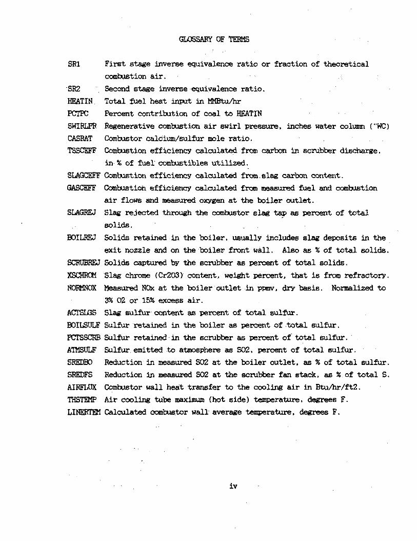
GKEARYOFTEBlS
SRl First 6-e inverse equivalence ratio or fraction of theoretical comwtion air. :,
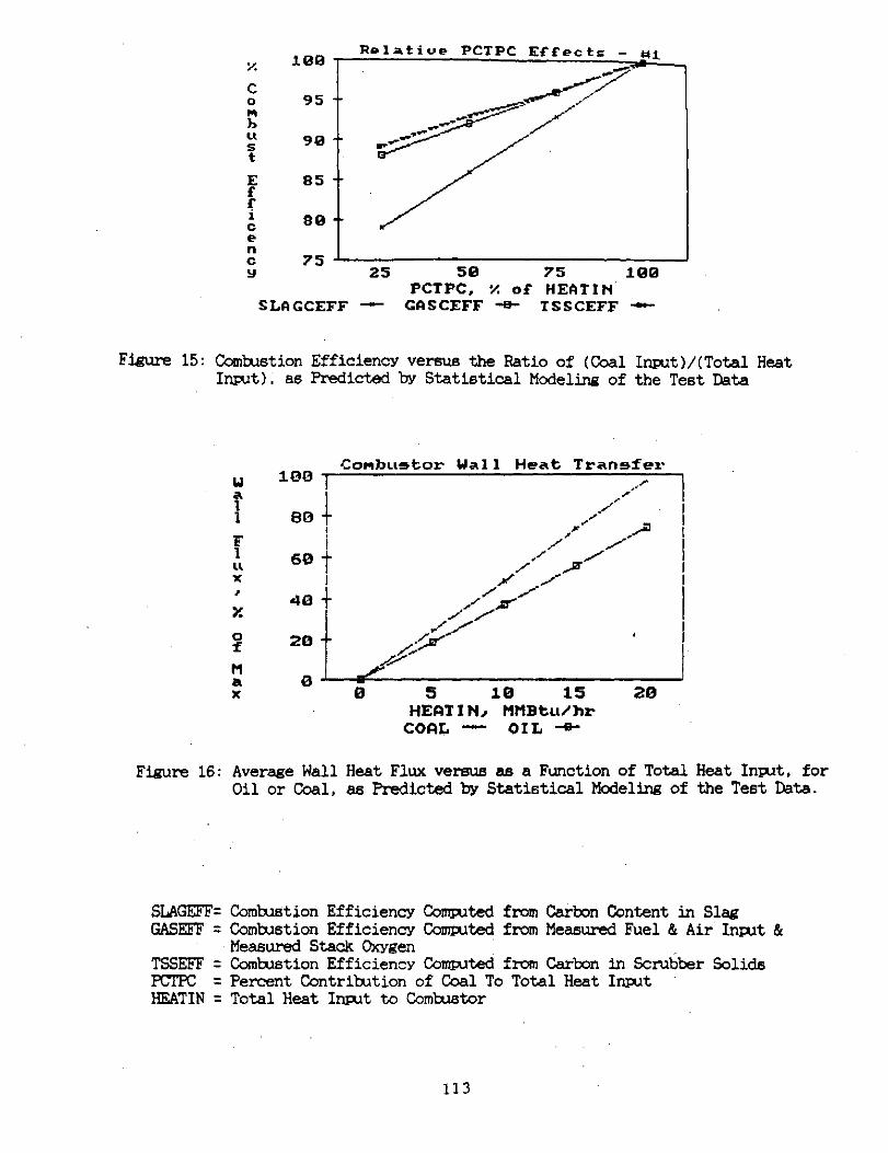
St2 ", Second stage inverse~equivalence ratio. RRATIN. Total fuel heat input in HlBx/hr
Percent contribution of coal to HEATIN SWIRLPR Regenerative combustion air swirl premura, inches water column ("WC,) CASRAT Comlaxtor calcium/6ulfix mole ratio. TSSCEFF Combustion efficiency calculatedfmm carbon in scrubbsrdischarge.
in% of fuel cMbJstible6 utilised. SLAGCEEF~Combxtion efficiency calculated f&mslsg carbon content. GAXRFF Cc&xt.ioh efficiency calculated from measured fuel and comtition
air flow6 and sea6urad oxygsn at the boiler cutlet. SLAGREJ Slag rejected +2mxghthe combstor slagtagaa psrcentoftotal
solids. WIm Solid6 retainedin the boiler. usually include6 slag deposits in the
.exit nozzle and on the~boiler front~,wall. Aleo a6 % of total solida. SCRUEW Solids capturedby the scmbberas pemantoftotalsolid6. XscHRoM 'Slag chroms (Cr203)~ content. weight percent, that is from refractory. NORKNCX Meammd NO% at the boiler'outlet .in pmv. dry basis. Normelized to
3% 02 or 15% excess air. ACl'SES Slag sulfurcontentas percent of totalsulfur. BOILSULF 5ulfu.r .x-stained in the boiler a6 percent of ,total sulfur. EC'lSSCllB Sulfur retained-in the scrubber a6 percent of total sulfur. ATMSULF Sulfuremitted to,atmosphers 6s SO2, psrcsnt of total sulfur. SREDBJ Reduction,in measured SC2 at the boiler outlet, a6 % of total sulfur. SREDFS Reduction in measured SO2 at the scrubber fan stack. a6 %,of total S. AIRFLUX Comtu6tor wall heat transfer to the ccoling air in Rtu/hr/ft2. THSTEMP Air cooling tub6 maximum (hot side) temperature. degrees F. LINlIRlBl Calculated cc&u&or wall average temperature, degrees F.
iV
Achowledsments
In addition to the DOE-CleanCoal Technology Prcgram, this work was "' sunxrted in part by the Pennsylvania Energy Daveloxarent Authority (WA), the PA. Power & Light Ccmpan~ (PP&Ll. and the Tampella-Keeler Company. .The author6 wish to note that the opinion6 and conclusion6 presented in this paper are their own and do not necessarily represent thcee of the project apcrisors, or any other govemrent agency. The author6 wi6h to express their appreciationfor their suppcrt and advice during the four year period of this project to Mr Arthur LBaldwin, Ix)E-Technical Project Manager; Mr.Uans Bickley, Mr.John Men&, and Mr. Joseph Garb&k of PDA, Dr.Heins Pfeiffer and Mr. Robert Johnson of PP&L, and Mr~~~Williem Morton and Hr.Bavid Cron of the.Tampella- Keeler Ccbpeny.
In addition, the authors wish t.c aclmowlsdge the work of Hr.Bmbrdn Borck on the ccmputer control system, Mr. lbne Bardo and Mr.Bsvid Alexander of C&I Boiler Coupany 'on the in6tallation. maintenance, and operation of the facility. Mr. Ed Caims'of~the Tampella-Kseler Cc6p6n~ for the operation of the boiler, Prcfeseor'Ch6rles Bar&m, ~Villanova U., for thermal analysis, Profess0rP.V: McLaughlin of Villanova U. for the stress analysis. Professor Bale Birr@son and Mr.R.Judkins of the Cak Ridge Fossil Energy Materials Labcratcry for the combator material6 analyses.
The authors also wish to especially express their appreciation to Mr. : Baldwin for his efforts on behalf of the project in the progrsmetic area, in securing the assistance of other DDE laboratories for materials analyses and for special test esuipnsnt. The latter were i.nstrum6ntalinpreventing premature shutdown of tests on several occasion6 during the course of the PrOhCt.
V
ksk? of the data generated in this~projsct relate6 to the performance of the CUmtmtOr,that utilizes prqrietary design and prccedure6, som6 of which weredeveloped independently of this Clean Ccal~prcject. As per the'terms of the Cooperative Agreaent between the Department of Energy and &al, Tech,~this data ha6 been supplied to DOE in a separate "Proprietary Cccument", concurrent-
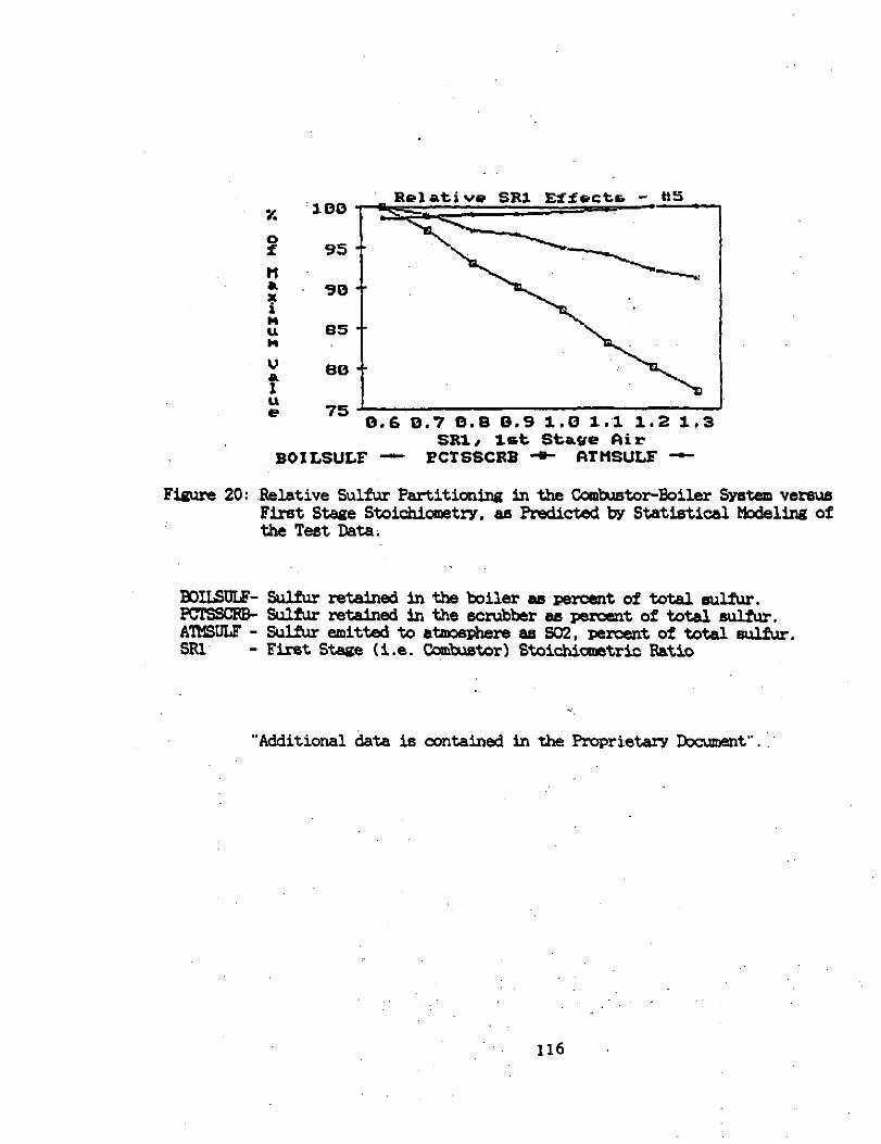
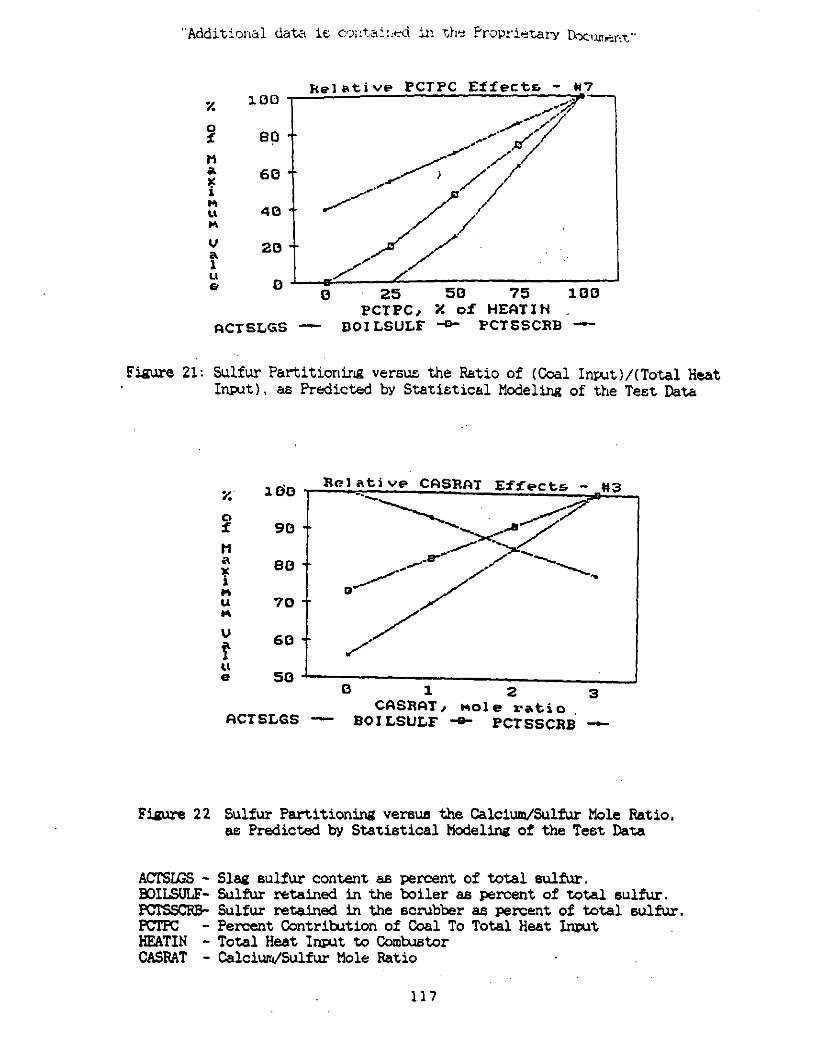
,ly with this Final Report. The author6 have p1aceda.fcotnot.e on each page in this Final Report which states that "Additional data i6 ccntainsd in the;Pro- prietary Dxumsnt". The.pages as: 35, 36, 37, 47, 56, 57, 59, figure6 8. 16, 20, 21, and 22. Also, Appendix II: Paes A-11-21, 22, 23, and 24, and figure6 S, S-2,,T, and U.
The Proprietary kxm6nt also contain6 additional Summary performance test data as .well a6 raw test data frcm representative test runs PC 9 and PC 26. (See list of test runs at the end of .Appendix "A").
In the course of several decade6 of F&D by Coal Tech's principals on a, nuder of advanced power systems, ithasbesnobserved thatinmanvcases capital and OperatinE a&Bhave a greater impact on energy costs than fuel costs and/or system efficiency. Therefore, Ccal Tech-s approach tc the air cooled ccmkustor ha6 been tc integrate the combustion and envircmtal ~, performance inside, the air cooled co&u&or, and to develop procedures that allow its fully automatic operation. It iS anticipated that this~apprcach will allow energy systems incorporating this combustcr to fully benefit from the low cost of coal and related solid fuels.
vi
1. SUWHARY
This Final Report presents the results of a three year demonstration test effort on a 30 MMEtu/hr comtustor retrofitted to an oil designed package boiler. In May 1990. this project became the first U.S. Department of Energy (DDE1 sponsored, Clean Coal Technology Program Project to complete its Phase III test effort. ,In addition to MIE. the $1 million project was supported by the Pennsylvania Energy Development Authority (PEDA) and the Pennsylvania Power & Light (PP&Ll Ccmpany. Project test work,was conducted at the Tampella/Keeler Co. plant in Williamspxt, PA. The praiect objective was to demonstrate a tschnolcgy whichcan be used to retrofit oil/gas designed boilers, and conven- tional pulverised coal fired boilers to direct coal firing, by using a patented air cooled coal combustor that is attached in place of oil/gas/coal burners. 'rxlring the Clean Coal project, the comtitor was operated for a total of 900 hours on oil, gas, and dry Fulverizsd coal. This includes about 100 hour-a of tests under other projects. One-third of the operational time was on coal, with 125 tons consumed. Evaluation of test results indicates that most of the Clean Coalprojectgoals have beenmet.
A significant part of the test effort was devoted to resolving operational issues ,related to uniform coal feeding, efficient combustion under very fuel rich conditions. maintenance of continuous slag flow and removal from the com- titer, development of,proper air cooling operating procedures, and determining camPonent materials durability.
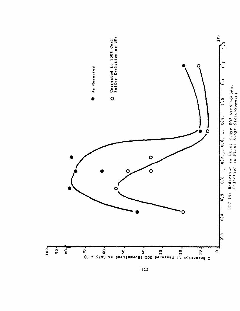
The second major focus of the test effort was on environmental control,. especially control of SC2 emissions. By using staged combustion, the NOx emissions were reduced by around three-fourths to 184 ppmv, with further r&x- tions to 180 ppmv in the stack particulate scrubber. By injection of calcium based sorbents into the comb.astor, stack Xl2 emissions were reduced by a '. maximum of 58% depending on the C&S ratio and combxtor operating conditions. In addition, -a small but significant amount .of the coal sulfur (maximum q 11%) was trapped in the calcium bearing slag. The test results suggest that further
significant sulfur retention in the slag is attainable. With sorbent injection downstream of the corntudor, tested in a preliminary fashionprimarilyunder the fly ash vitrification projects (Ref.l.1, page 2.A). a maximum of 82% 902 raduction was achieved.
1
Slag retention in the combxtor is a function of the combustor~ stoichio- ,: metry, decreasing with increasing fuel rich operation. A5 very fuel rich operation appear6 to increase sulfur reduction. a significant portionof then, tests were performed under these conditions. Slag retentionunder fuel rich conditions, is lower than that att.aFnable under fuel lean combustionconditions. The mitude of a6h/elag retainsd in the combustor and boiler floor waS;ob- tab-al from the ash collected in the,eczubber. It showed that on:average 72% of the ash/reacted sorbent was retained in the comtitor/boiler for all the test runs with a ranges of 55% to 90%; Under near ~stoichiometric conditions, the average value was 80%. Of the 72% value, about 55% was retrieved:fkom the slag on the combustor wall, exit nozzle; and slag tank, with the, other 17% being ash deposited on the floor of the furnace.
A6 a benefit to the present project,' in tenne of extended durability and operational ts6ting, as well as evaluation of the range of alternate comix6tcr applications, Coal Tech conducted tests under other projects, interspersed with cleancoalProk.ct testing. These other projects dealt primarily with the conversion of utility flyash or municipal solid waste incinerator ash to slag. Pertinent results of these test6 are mentioned in this report where appro- priate. Detailed information on these projects may bs found in the Coal Tech rtwx-ts cited on page 2A, references 1.1,1.2, and 1.3.
The data base for continuous and long duration operation of this combu6tcr has been established. Near the end,of the project, this data base was inccqo- rated under other proiecta into a micro-computer PX-QXSS control system that will allow complete automation of the comtustor's operation. The data base now exist6 to scale upthe comlazstor to a 100 MHBtuIhr thermal input. Usins.the above SQx/?IOx data, Coal Tech's economic a~lalvsi6 of the application of this combustor for emission control in coal fired utility boilers indicates that it may be lower in cost than other furnace sorbent ihiection processes. The combustor may also be economically attractive in certain industrial bAler applications, e.g. vitrification of fly ash to slag, and incineration of refuse derived fuels (FDF).
2
References to Section 1.'
1.1. "Use of a Cyclone Comb&or to Convert bnicipel Incinerator Fly Aeh to Inert Slag:', US EPA-SBIR Phase I Project Final Report, EPA Contract No. 68D90117, Period of Performance: Sept. 11, 1969 to April 30, 1990. 1.2. "Use of an Air Cooled Cyclone Coal Corntudor to Convert Aeh to Inert Slag", DOE-SBIR Phase I Project Final Rep3x-t. DOE 'Corntract No:DE-ACOl- 88ER80568. 1.3. .-Use of en Air Cooled Cyclone Coal Combstor to Convert Ash to Inert Slag", WE-SBIR Phaee II Project Quarterly Reporb. DOE Contract No. DE-ACOl- 88ER-80568. May, 1989.
2A
2. BRIEF CVIBVIEW OF PFXMECT
. . 2.1. m
The Coal Tech Clean Coal I project was conducted in three phases. Phase I comisted primarily of activities involvina design and specification of equip- ment peripheral to the combxtor and boiler. including coal and limestone dry feed systems, the stack particulate scrubber, several air blowers as well a6 the varicm squipmsnt required for flow stream measurement and control. In addition, efforts were initiated to acquire the necessary environmental regulatory operating permits.
Iku-IngPhase XI. Coal Tech installed the esuipment~desigmd in phase I and also conducted several one-day shakedown tests on the newly installed equipmerk tc determine its operability.
During Phase III the initial aim wa6 to develop a data base associated with comtmtor operation and to identify and ~resolve materials and hardware issues related to actual retrofit. The ultimate aim of Pha6e III was to conduct mlti- day test.6 dmmmtrating continuous operation.
The following test objectives were specified tc impleumt the joint. objective6 in the Clean Coal project cooperative aa;reement: _.
1. Ccmtaastor operation with coals having a wide range of sulfur contents.
2. 70 to 90% reducticm in Bulfur oxides in the stack, with maxim.16 sulfur retention in th6 slag. ,,
3. NOx reductions to 100 pr.61 or less.
4. The solid product6 from the comtu6tor, i.e. sl6g/6orkent/suh?ur com-
powxk, are enviromrmtall~ inert or can be readily converted to aminert~fonn.
5. Achieve high combu6tor slag retention and removal, with the goal beihg 90% - 95%. a6 well a6 compliance with local particulate emission standards.
3
6. Achieve efficient combustion under reducing conditions. .~ _I.
7. Determine combistor turndown, with a 3 to 1 objective. .~ :'
8., Evaluate materials compatibility and durability.
9. Operate the ccmbustor for about 900 hours of steadv state operation on coal uith frequent start-ups and shutdowns.
10. Develop safe and reliable combxtor operating prucedures.: :~ :
. 2.2. ,Proiect
Appendix III contains a photcgraphic record of the project. The photo-, graphs were selected to .shou the various stages of the-project. ,ir@uding the original installation of the equipment; various features of its operation. such as slag rsmoval. exit nozzle luminositv,~ steam blowoff plume, etc. Also, the comtitor-boiler internals after operation; wall,damage and repairs of the comtustor-exits nozzle wall: ~and,modifications to then original equ@aent as a result of the test,activities. The photcgraphsuere selected ti,give,:a visual chmnolosical record of the Project. with emphasis on the features of ,the cc&u&or ~inatallation. the type of operational problems encountered and solved, and the operational features of the combustor. The.selections do not reflscton their relative importance to the success of the pro.iect
'l'he.follouing sections briefly summarize the effort in the three project phases. "he acccmPlishn?ents will be Presented in. more detail,inthe next eut-
S~tiOIl.
2.2.1. Pllase
In work.Pre-dating the Clean.Coal:Technoloa~ I Project. the Coal Tech air cooledcyclone coal'combustor was designed, fabricated. and retrofitted to a 23 MMBttir oil designed nackage boiler at the Tampella facility in Williamsort,
a one yearperiod during 1985-6. Installation beganin late 1986 and it was completed in early 1987. The original installation was for use with low ash.
4
low sulfur, coal-water slurry fuels. No particulate stack SCrUbher orsulfur control system wa6 included in this original system. That effort Culminated with initial tests on the combxtor in the Spring of 1987.' using a coal water slurry. 'Ihe comtistor was operated for a period of 40 hours on coal-water slurry fuels at about 17 MMBtWhr. Comtustor operation was as per design;' An important result.was thatcomtistor xx-e-heat to operating temperature was accom- plished with the slurry fuel. This initial operating experience ,wa6 a major factor in the preparation of the test plan for the D3E Clean Coal project.
The Clean Coal project kegan in March, 1987; In Phase I, the auxiliary ewipvent necessary to allow dry Mverized coal firing ua6 designed. This included a 4 ton, on-site pulverized coal storage system, a Pneumaticcoal delivery system to the comtuehr, a l/2 ton dry &verized limestone storage and pneumatic feed s~sten; and a,wet stack Particulate scrubber. Coal. pllverization wa6 off-site with regular fuel delivery hy pneumatic tanker truck. (ktmamial design6were u6ed for each system, and it wa6 planned to mW&ase the equirxnentinFha6e 2. .~
The secondpart of Phase 1 consisted of preparation of the required project environmental reports, and initiation of process to obtain the various emviron- mental parmits for op6ratins the comwtor on ~lveriz.ed coal. These parrnits included an operating permit from the PA Department of &n+'onm6ntal Resources (DEB), which included an initial approval of,the operating plan, followed hy an air quality emission permit. Both permits were obtained inFhase~Y?he second permit "66 for the discharge of the scrubber waste water$nto the williamsport sanitary system, which had been obtained prior to the start of the Clean Coal project. The third Permit was for the disposal of the solid waste prcduced during oomhustor operation in an a~~rov6d landfill. This application wa6 delayed until the start of Phase 3, as a PrOfiIe of the solid mast-6 stream was required to file for th6 permit.
Fha6e 1 was completed on schedule in May 1987. During the traxxition to Phase 2, pmwremen t of the long lead items required for the coal~convenaion
km. 5~ 1.
2.2.2. Pbaae 2: Fabrication.
Phase II c~nced in July 1987. A ccnsercial 4 ton ~lverizsd coal storage and delivery system wa5 procured. As no connnercial pneumatic coal and 'limestone feed systems were available, they were fabricated and assembled to Coal Tech~s~deskns. The original plan to purcha5e a recirculatingparticu-'. late scrubb5r system and install.it inside the boiler house.,was altered to a, roof mounted once-through system. The former design apprcachhadbeen selected due to concern over waterline freezing and boiler roof weight bearing capabili- ty. However, ita cost was considerably beyond project res ources, and Goal Tech ~es~edendpmntredtheonce-through~fm3untedsysteman apiecemeal basis. The installation of this,ecuipment was completed in November,l987,~and the two planned, one;day, shakedown tests .were performed to evaluate the new ecuig75antperformarge. One test was perfonaed with coal water slurry and the second test was performed with dry pulverized coal.
Then first test revealed a design flaw in the secondary air fan which provides the combustor cooling air and most of the combustion air. The fan operated on the wrong side of the fan curve which caused damaging vibration5 and extremely high noise levels; Coal Tech found tempxary solution to this problem by modifying the fan inlet. However, during the combxtor~overhaul in. the Springof1988. the fanwas returnsdtothe manufacturer for rebuilding and it has operated quietly and without problems since that tims.
The second shakedown test was the first one with dry pllverized coal. .This test revealed that all the new esuiment was ~functional. The test was j.: performed with a low volatile, (<20% volatile matter);refractory ash .CT250 > 2600°F, PA bituminous coal. The test showed that the air cooled refractory liner ,was considerably outside the optimum wall heat transfer range for this~. coal. In addition, it was found that the coal feed system.prduced up to 17% feed fluctuation5 of several minutes frequency. Finally, it was determined that dry zulverized coal could not be used effective19 to preheat the cc&u&or wall6 to operating temperatures. However, :a5 the entire comIxator- boiler system operated within an acceptable dry wlverized coal firine .~ envelope, I: was dezided to proceed to Phase 3. with initial focus on the coal feed and combustor wall Dr-e-heat.
6
2.2.2. Phase3:p
Phase 3 bemn i.p November 1987. In the period between E/87 and 5/90. 26 Phase III combustor tests were performed for a total operating time of around~ 800 hours; consuming about 125 ton6 of coal. All but the last seven tests ~were nominally 24 hrs in duration, including heatup and cooldown on auxiliary fuels. After December 1988, the balance of the tests were of multi-day duration.
~ The tests can be divided into the following groups, with major overlap among the various groups:
A- The initial group of tests was aimed at improving the combustion effi- ciency'from the 80% level measured in the first tests. and to reduce the coal feed fluctuations. The latter goal was achieved by a series of incremental changes to the coal delivery and, pneumatic feed system, which eventually reduced the feed fluctuations from 17% to a little over 1%.
The combustion efficiency was gradually improved to the 95-99% range by using an oil burner to preheat the comkustor walls to operating temperature. instead of the planned use of coal. Incidentally, this change in the pre-heat from ccal to oil was a maior reason for the discrepancy between the.oriRinallv planned 900 hours of coal fired operation, and the actual value which was about l/3 of that. In addition, higher volatile and less refractory ash coals were used. and limestone fluxing was added to improve slamming performance. However. the mismatch in thermal properties of the corn&&or refractor-v wall with the combustion ga6 heat transfer resulted in operation of the combxtor wall beyond its safe operating envelope. This caused refractory wall failure in several sections of the ccmbustor roof in February 1986. which necessitated a complete disassembly of the combustor. .A new refractory liner was installed having therm51 properties consistent with the wall heat-transfer. Also. the wall temperature diagnostics a5 well as the air cooling oneratti procedures were revised in light of the prior test experience. The combustor.was reassembled and one day duration testing resumed in May 1988. Since that time the comb-&or wall has operated for almost 800 hours with only occa5ional minor patching required. Since the introduction of computer control of the comk&.or's operation, and a redesign of the comlxstor-exit nozzle interface in the Spring
of 1990. no ccmbu6tor wall patching ha6 been nece88ar-y. 7
The second set of tests was primarily aimed at solvin6 the slag tap plug- ging problem in the combstor.~ .Very early in the test effort, olzeration wa6 continued for a number,of hours after the slag tap'plugged and a nearly 1 foot. thick layer of frozen slag formed on the floor of the combustor. which had 'cc,~ be removed manually by chisel and h-r. After that time. all tests were '~ terminated when the sla6t~4'pl~z@ad~ By a series of trial and error methcds~. a combination thermal and mechanical slan breaker procedure was developed in the course of the project so that by the beginning of 1989. very few test were terminated due to slag tap plugging. Only one of the seven multi-day test5 :was terminated several hour5 early on the last day of the test due to a human error related to the operation of the slag breaker.
The third group of tests was ,related to durability of the combustor wall, materiale. The air cooled liner test results were noted above. The second materials area related to the comtustor exit nozzle, which operated under near adiabatic conditions. The material used in the the exit nozzle withstood the aggressive slag environment throughout the test effort. However, the nozzle- comtistor interface, as well a6 the nozzle-boiler wall interface suffered materials breakdowns due to differential expansion or selection of ceramics with poor slag or thermal resistance. The boiler front wall was redesigned in mid-1988. The combustor-exit nozzle interface was redesigned this year. l'he5e changes have resulted in a design suitable for long term -ration. However. the present design requires a small amount of additional wall cooling tc allow round-the+lock coal fired operation at fully rated ccal fired thermal input. The combustor wall, on the other hand, .is currently capable of operating continuously at full rated therm51 inmt.
The fourth group of tests were focussed on'enviromntal control of NO,;
SO2 and particulate emissions. The results will be sunanarized in the next sub- section. For present purmses, the item of major interest is that the'gas emis- sion controls require very fuel rich operation. Therefore. amsjor aspect of the test effort wa6 to achieve efficient comb-&ion under fuel rich conditions. During the course of the tegt effort, the combustor air flows were re-arranged a number of time5 until condition5 at Which air cooling. wall temperature. slag- ging, and comtustion efficiency w"- re optimised at fuel rich conditions. This result was achieved inmid-1989, and nearly ail subsequent test5 were performed at fuel rich conditions. However, fuel rich operation resulted in reduction of
8
slag retention. At the end of the test effort, considerable progress in So2 reduction had been made. However,.a major project objective,of high sulfur capture in the combustor and retention in the slag removed from the combustor
had not yet been achieved. In subsequent post Clean Coal project tests, it was discovered that a high frequency coal feed fluctuation existed throughout the test effort. It is suspected that this IMY have adversely affected the sulfur capture prccess. Very recently this fluctuationhas been dampened, and it is planned to perform future sulfur capture experiments under fuel rich operating conditions.
The next group of bSt6 were to i.ntEWate all the operating data base, gained in the project into a computer controlled operating system. The nece66aIY eNiFTWnt was installed prior to the last test of the Clean Coal project. However, it was.only after the project tests ended that this couazuter system has been placed in operation. The prozess control software incorporates the operational data base. Its use in a series of tests since the completion of the Clean Coal project test6 in hay 1990, ha5 resulted in a major improvement in the controllability of the combustor. It is anticipated that with a number of additional controls relate&to ~slag tap operation, and combustor start-up and shutdown, it will be possible to operate ~the comb.&cr completely automatically.
Beginning in the Fall of 1988. the Clean Coal Phase 3 test effort was focu6sed primarily on longer duration operation., In &cemb5r 1988. the first three day duration test with overnight shutdown wa5 implemented. Overnight shutdown was necessary because the comb*stor-boiler controls were manual. and required continuous operator supervision. To allow longer daytime periods of coal fired operation, and more rapid heatup to operating conditions,, the combustor+oiler controls were converted to automatic. unattended. overnight
.opsration on pilot gas fuel in early 1989.
Ee&.nning in March 1989,, a series of five 4 day tests with round-the-clock operation were implemented. Nighttim operation wa6 on pilot natural gas.and
daytime opration wa6 on oil, for heatup and ccoldown, and coal. These tests were interspemed with one to twc day tests on the comtu6tor for other pm- jects. A5 a result by the end of the Clean Coal project in May 1990, a total
9 ~.
of 900 hours of operation had been completed, of which 100 hours were on two other DOE and EPA R&D projects on fly ash vitrification. As of the'date of this report, the combxtor has operated an additional 100 hours of daytime coal fired operation. Most of the test goals were directed at optimisation of comtitor and support equipment operation as well as developing the operational database a5scciated with environmentally acceptable performance.
For the~tests, eight different Pennsylvania coals having different sulfur' content6 were used. Parametric testing of comtustor operation wa5 evaluated with regard to environmental and process effects. Parameters tested included first and second stage stoichiometries, coal type, coal firing rate, calcium/sulfur mole ratio, and 50 forth. In May 1990, Coal Tech completed the planned test effort on its IDE Clean Coal demonstration project. Thefinal effort on this project ha5 been analyzins and evaluating test results. and ', preparing the Final Report.
The Clean Coal project Cooperative Agreement specified five technical objectives. To implement these objectives. the followit-@ 10 Sub-ObjeCtiVeS were defined. The following is a swmnary of the accomplishments a6 compared to the sub-objectives listed in section 2.1.
The first objective was to use Pennsylvania coals with up to 4% sulfur content. About eight different PA. bituminous coals with sulfur contents ~~ ranging from 1 to 3.3%, and volatile matter contents ransing from 19% tc 372, were tested.
The second objective was to achieve 70 to 90% SC2 reduction at the stack. with maximum eulfur encapsulation in the slag. With regard ta the first part of the objective, a maximum of over 80% SC2 reduction maaeured at the boiler outlet stack, using sorbentinbction inthe furnace at various, C&S ratios. However, this result is besed on limited data from work,mainly conducted under the ash melting projects. It should be emphasized that these results were ob- tained during preliminary trial mm which made no effort at parametric optimi- sation. Until further tasting can be performad, a full analysis of the results is not possible. Gocd progress was being made at the end of the~test effort
10
toward meeting the second par-t of this objective. which,requires sorbent in.iec- tion into the combustor. ,A maximum 602 reduction of 56% was measured at the stack with limestone injection into the combustor at a Ca/S of 2. A maximum of one-third of the coal sulfur was retained in dry ash removed from the combustor and furnace hearths, and a high of II% of the coal sulfur was retained in the slag rejected through the slag tap. Further slag sulfurretention is definitely possible by increasing the slea flow rate, by further improvements in fuel rich combustion, and ~bv further improvea+nts in sorbent-gas mixing.
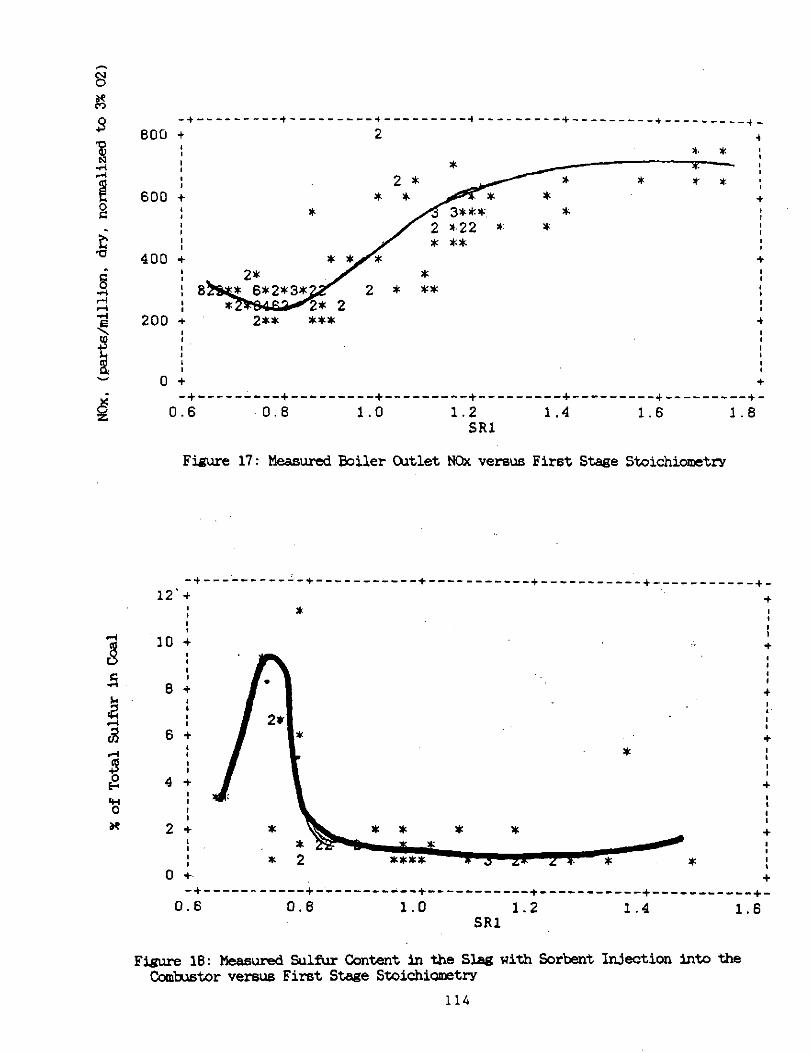
The third objective was to achieve NC& reductions to 100 ppm or less. With fuel rich operation of the combustor, a three-fourths reduction in measured
boiler outlet stack NC% was obtained, corresponding to 184 Pam. An additional 5 to 10% reduction was obtained by the action of .the wet particulate scrubber. resulting in atmospheric NOx emissions as low as 160 prm.
The fourth objective was to produce an inert solid waste. All the slag removed from the ccmixstor has produced trace metal leaohates well,below the EF'A Drinking Water Standard when subjected to the Ep TCX test, and has yielded sulfide and cyanide reactivities within the regulatory limit.
The fifth objective was to achieve SO%-95% slag/sorbent retention in the combustor. and meeting local stack particulate emission standards. The second part of this objective ,was met with the wet venturi particulate scrubber. To- tal slag/sorbent retention under efficient combustion operating conditions ave- raged 73% with a range of 55% to 90%. Under more fuel Lean conditions. the slag retention averaged 60%. In Past Clean Coal project tests on fly ash vitri- fication in the combustor, modifications to the solids injection method and in- creases in the slag flow rate produced substantial increases in the slag reten- tionrate.
The sixth objective was to achieve efficient combustion under fuel rich conditions, was met. Comtition efficiencies exceeding 99% were obtained after props- opsratingm-ocedums were achieved.
The seventh objective was to achieve a 3 to 1 combustor turndown. Turndown to 6 !PBtu/hr from a peak of 19 l%Btu/hr was achieved. The maximum heat mt during the tests was around 20 MWStu/hr, even though the combustor was designed
11
for 30 MMERu/hr and the boiler was thermally rated at around 25 Hb!Btu/hr.~ This situation was due to facility limits on water availability for the toiler and' for ooo1i.n~ the combustor. In fact. even 20 MlBtukr wa6 borderline, so that most of the test& was conducted at lower rates.
The eighth objective was to evaluate materials compatibility and durabili- ty. Different sections of the comktor have different materials requirements. Suitable materials for each section have been identified. Also. the test effort has shown that operational procedures are closely coupled with materials durability. In other words by implementing certain prozedures, such a6 changing the combustor wall temperature, it has been possible to replenish the combmtor refractory wall thickness with slag.
The ninth objective~was to operate the comb&or on coal for approximately 900 hours of steady state operations with frequent start-up and shutdowns. The combustor's total operating time during the life of the Clean Coal project wa6 abut-900 hours. This included about 100 hours operation in two other fly ash vitrification test projects. of the total time about one-third was with coal. About 125 tons of coal were consumed.
The tenth'and most impztant objective was to develop propar couhtor operating procedures. Not only were procedures for properly o=rating in air cooledcomtustordeveloped, but the entire operating database was incorporated into a computer controlledsystem for automatic comhstor operation..
In conclusion, Coal Tech's-gcal for this'project was to validate the air cooled combustor'at a commercial scale. This was accomplished. While the combustor is not yet fully ready for sale with commercial guaranties, it is ready for further major scaleup for application to commercial projects such a6 waste solid fuels, limited sulfur control in coal fired toilers, and ash to slag conversion.
3. DETAILED DESiCRIPTION OF PROJE'X WOAK
The discussion in this section will highlight those aspects of the project effort that are significant in evaluating the project accomplishments and directions for future work. The material is not a reproduction of the discussion contained in the various project technical reports, which,have been previously submitted to DOE.
In work pre-dating the Clean Coal project, the Coal Tech air cooled cyclone coal combustor was designed. fabricated. and retrofitted to a 23 MMBtu/hr oil designed. package boiler at the Tampella/Keeler facility in Williamsport, PA. The combtor design effort began in late 1984; combuetor fabrication required a one year period in 1985-6. and installation began in late 1986 and it was completed in early 1987. The original installation was for use with low ash. low sulfur, coal-water slurry fuels. No particulate stack scrubber or sulfur control system was included in this original system. Thateffortculminated with initial tests on the comtxstor inthe Spring of 1987, using a coal water 6lLJ.rry. The combustor was operated for a period of 40 hours on coal-water slurry fuels at about 17 MKERu/hr: Comb.&ator operation was as per design. An important result was that ccmbustor pre-heat to operating temperature was
.accomplished with the slurry fuel. lhis initial operating experience was a major factor in the preparation of the testplan for the Clean Coal project.
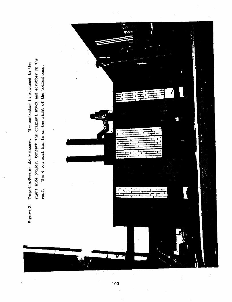
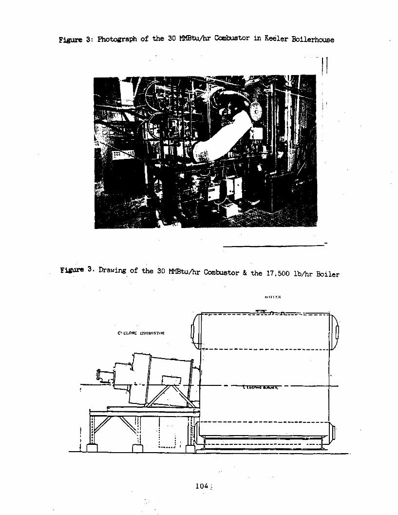
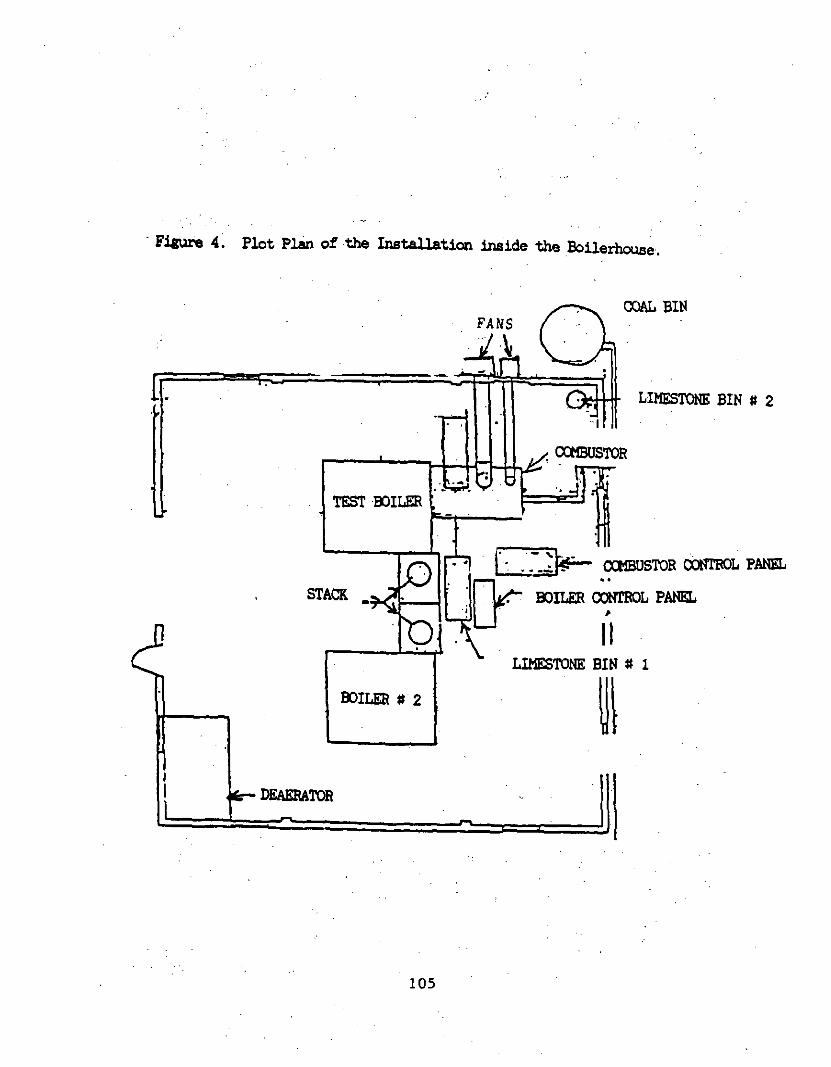
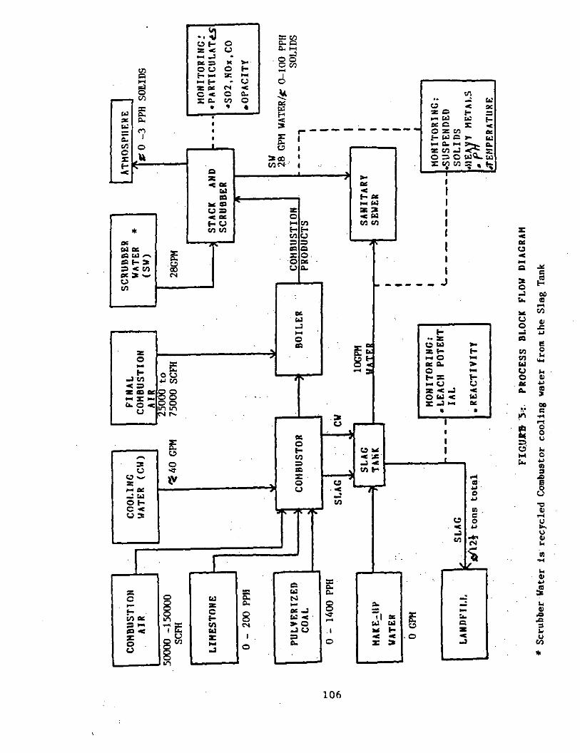
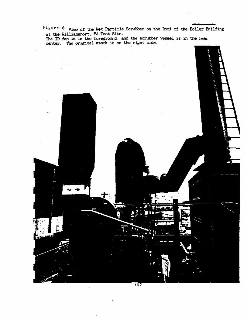
The combustor and the test facility will bs described below. Here relevant drawings and photcgraphs will be introduced to clarify the subsequent discussion of the Phase l.desiw effort. Figure 1 is a schematic diagram of Coal Tech's Advanced Air Cooled Cyclone Coal Gom&stor. The combustor is attached to a 17,500 lb/hr of saturated steam (23 HMStuflr) D frame,oil designed, package boiler in the.boiler house of the Tampalla/Keeler Company in Williamsport, PA. The latter is shown in figure 2. Figure 3 is a side view photograph of the ccmbustor as it is currently attached to the boiler while figure 4 is a plot plan of the installation. F&u-e 5 is a process flow block diagram of the coal fired combustor-boiler 6~st.m. Figure 6 is a photograph of the stack scrubber on the roof of the boilerhouse.
13
The Clean Coal project began in March'1987. In Phase I, the auxiliary equipment necessary to allow dry pllverized coal firing was designed. This included a 4 ton on-site pulverised coal storage system, a pneumatic coal delivery system to the combustor, a l/2 ton dry pulverised limestonestorage and pneumatic feed system, and a wet stack parti&lati scrubber. Coal pulverization was 'to be off-site with regular fuel delivery by pneumatic tanker truck. Coaxnercial desizns were used. and the entire system was planned for Phase 2 purchase. The basic design consisted of an upper (4 ton capacity) bin which discharged automatically it& a small lower bin that was integrated with a screw feeder. The latter discharged the coal into a pneumatic air line that deliver& the coal to the comb&or. Injection was either axiallythough a pintle, or off-axis, downstream of~a pneumatic coal flow splitter.
A limestone bin, with a i/2 ton capacity was placed alongside the comlxstor, and it,delivered the powder to the comlxstor in a manner similar to thecoalfeed.
To control stack particulate emission a wet particle scrubber was designed. with a recirculating water loop. The de&n called for placement of'the : scrubber inside the boilerhouse due to concern of winter freezing of the water loop, as well as concern over. inadequate roof load capability of the boilerhouse.
The slag removalsystemdesignconsistedof a simple drag conveyorwhi~ removed slag dropped into the slag tank l&tedundemeaththecomt~st,or.
It was planned to Fwrchase all this equipment commercially. In fact, certain comzonents were not available or they performed poorly, and Coal tech had~to modify them extensively.
An existing sophisticatec'O'J2:C!Q, NO,. s02, HC stack gas sa&ling system in a Keeler test facility adjacent to the combustor facility was made available for use in the combustor project.
14
A second major activity of Phase I ras the penittinfz necessary to implement the Phase II and III test efforts. The water discharge permit was obtained from the Williamsport Sanitary Authority. while the application for the air emission permit was filed with the Pennsylvania Department of Environmental Resources (PA DER), F%u-eau of Air Guality Control, with subsequent approval of both the Test Plan and Operating Permit in Phase II.
Finally,,the procedure for obtaining a solid waste disposal permit was initiated with the PA DER, Bzeau of Solid Waste Management, including provision to accumulate and storeslag samples on site for subsequent
representative sampling and analysis as per the required Module 1 in Phase 2 & Phase 3 testing. However, it was discovered later in the project that the slag was covered under the Pennsylvania Coal Waste Product Recycling Actand, as such, did.not require extensive testing/analyeis~ to obtain disposal permits. In view of this. plus the fact that the Module 1 testing had already been performed, showing no hazardous solid waste characteristics; disposal of most of the slag and bottom ash produced in the tests was at the PP&L Montour solid waste facility. However, solid waste characterisation testing of the ,slag was still deemed important in overall development and demonstration of the combustor and we therefore continued to monitor this substance. Late in the phase 3 tests, PP.!& could not accept the slag -use a-significant quantity of material consisted ,of large slag blocks. In addition, it was necessary to dispose of refractory removed from the comtitor. As a result a Module 1 application is now being processed by a local landfill. Ixle to the lengthy filing period, it is planned to diszoae,of the remaining material at a secure private landfill.
.,Another activity of Phase I was the compilationand preparation of the necessary documentation as specified in the Cooperative Agreevat and the preparation of the appropriate reports, including an Fnvironmental Plan Outline and the Environmental~Plan itself. These documents are on file at COE and will not be reproducedhere.
15
In Fhase II, the ecuiFment designed and selected in Phase I was installed at the TampellaKeeler facility. tiring installation the stack scrubber design was modified for placement on the roof of the boilerhouse, as opposed to inside the building, as in the original design. It was determined that the installation cost inside the building was much greater than the roof installation. The original-contractor that erected the boilerhouse was able to ascertain that the rcof bearing load was sufficient for this purpose. A, seconddesignchangenas touseaoncethroughplainsteelsct~bbervessel~ instead of a stainless steel scrubber vessel with a recirculating water system. This reduced the cost of the scrubber system by a factor of 5. The decision to proceed with this approach was based on Coal Tech's assumption thatthe use of lime injection in the combxtor would result in a basic water flow in the scrubber, which would reduce the corrosion rate substantially. This proved to be the case. The pH of thescrubber water ranged up to 12. The duct work and the scrubber fan were redesignedandprccured separately.
In nearly 3 years of operation the scrubber operated very statisfactorily. even in the winter, with air temperatures as low as S°F. To prevent freezing, the water lines were drained sfter each test. It was necessary to rearrange the water discharge to assure propar gravity flow for drainage Wpases. The only problems encountered were erosion of the scrubber vessel inlet scroll which~ was caused by the fact that the wall thickness was too thin at that location. This section was replaced with a section of thicker, erosion resistant steel. In addition, the scrubber inlet duct was not properly supported which caused a. shear tear in one wall of the inlet vessel. This was also readily corrected. The final problem with the scrubber system was damage to the fan wheel. which had to be replaced. It was not certain whether this was caused by inadequate mintenance. e.g. regular fan wheel cleaning and fan shaftbolttightening. or whether it was caused by residual debris thathad not bsen removed from the scrubber vessel after its repair. These three problems occu&'in December 1989. and it is suspected that the fan problem was caused by flying debris.
A commercial, 4 ton capacity. dry Fulverized coal storage and delivery system was PIZCUZ&. The originalplanhad been toraxchasethepneumatic
16
conveying system as part of the Coal system. However, the high cost and limited commercial availability of a complete system resulted in the decision to design our own system. Various size sductors were tested with Coal Tech
'des&ned .flow splitters to determine the appropriate component sizes. The final design 5elected allowed coal feed of UP to 3/4 ton per hour with multi- point off axis injection in the comb-&or. The. limestone feed 5ystem~was limited to only about 200 lb/In capacity due to the small size of,the limestone injection tubes in the comtustor. This proved to be a s&nificant drawback in sulfur capture tests in the F'ha6e 3 effort. To partially correct this problem, one of the coal ports was used for limestone injection. However, this was not a,satisfactorv solution as sorbsnt-gas mixing was not as uniform. (It should benoted that Coal Tech has recently installed a new solid5 injection systems that would allow lhxzstone injection rates in excess of 1000 lbhr at off-axis locations. )
In addition, a 1000 lb canscity liuestone ~storage and feed system was fabricated and installed alongside the comb&or.
As noted in the Phase I section, an existing gas sampling system in an adjacent building was made available for our use during this project. In Phase II, sampling lines were installed to allow extractive comtistion gas sampling from either the boiler outlet, upstream of the scrubber, or from the scrubber fanstack exhausting to atmosphere.
Although a 51~ removal system had been designed prior to Phase~I, it wa5. decided to delay installation of a continuous slag removal system until~the result6 of early testing could provide a determination of the nature of the Slas. Ck~ing to slag tap operation problems in the early F'hase III tests, a continuous slag conveying system wa5 not procured until later in Phase III.
This conveyor, which is shown in several photographs in Appendix III, proved to be of very poor design, as it'was very prone to jamming. After one modification by the original manufacturer, Coal Tech made a number of incremental improvement5 to this conveyor: However, even at this date the unit is still prone to janrning. and for future multi-day tests, Coal Tech will use the experience gained to-date to design a new slag conveyor.
17
Two comtustor shakedown tests were implemented in Phase II. The originally planned tests were to consist of two. one day tests with dry pulverised coal (PC) to establish the performance of the scrubber and the PC feed system. This plan wa6 modified to a new test sequence in which the bulk of the first test was to be performed with coal water slurry fuel, with a brief operatingperiod ondrvpC. The second test was to remain unchanged with dry PC operation. The change in plan6 was motivated by the fact that both the ECNbter and pneumatic feed SYSt.@JE for coal and limestone'wers purchased a5 individual components-: : from multiple suppliers. Ther6fox-e.~ a prudent approach to test the scrubber first, using the proven slurry fuel, was followed.
The first test, -which achieved 10 WBtu/hr slurry firing, showed good scrubber performance but identified excessive noise and vibration of the combustion air fan as a problem. The details of this problem and its resolution are presented in section 3.3.3. Briefly, it was determined that the fan had a design defect and that it was operating on the wrong side of the fan curve. Coal Tech determinedthatby increasing the inletopeningto the fan the vibration could be eliminated. However, the fan noise was still unacceptably high,. As a result. when the comk&.or wa6 rebuilt in March 1908, the fan was returned to the manufacturer for in6tallation of a new:-fan wheel. Since that time the fan has operated quietly and trouble free.
In the second test, 17 HMBtuAu- of dry PC was fired under fuel rich conditions. The coal storage and delivers system performed well. as did the scNbber. However, combustion efficiency was determined to be only around 80%. This problem and its resolution are also discussed insection 3.3.3.~ Briefly. the problem was caused by noor slagging on the coutitor wall and very high coal feed fluctuations. Phase 2 was completed in November 1987.
18
3.3. pIms&kJ3-
The original Phase III test plan for the dry pulverised Coal tests was developed on the basis of experience gained in earlier tests on this combustor with coal water slurries (11. It was assumed that after a brief checkout of the new dry pulverizsd coal storage and pneumatic feed systems. and the stack gas scrubber, that coal tests of increasingly longer duration could b6 imple- msnted. However, as more operating tima on H: was accumulated. the original test plan was modified to focus on technical issues which were discovered dur- ing testing that required additional work. For example. UXX-~ extensive paran&-
ric tests were necessary to deal with the refractory ash properties of the test Coal which made effective slag flow very difficult. This was not totally unex- mtsd since in reviewing the literature on commercial and advanced cyclone com&ator6. it was noted that considerably lower ash fusion temperature coals have been used. While good combustion efficiency and slag flow were eventually achieved, it recuired considerable develoPment work, including the refurbish- ment of the ceramic com~tor liner when the~combustor was inadvertently ore- rat-&outside its designsd thermal envelope. Another factor which impacted the tsst plan was the difficulty encountered in-the operation of the dry PC storage and feed system. This commercial system required extensive modifications before reliable and steady coal flow to the combustor was achieved.
Another major factor that influenoed the total operating tims on coal was the finding that dry nulverized Coal Could not be used to pre-heat the combustor to operating temperatures. This statemant resuires clarification. Coal could be u6sd to pre-heat the co&u&or. However, if the walls were too Cold to slag the Coal ash. a large fraction of the coal particles would blow out of the comtu5tor. The furnace section of the package boiler is not designed to bum coal. Therefore, significant unburnt coal would entrain in the stack exhaust and overload ths ECNbber. For this rea5on, oil firing uas used to pre-heat the comtustor wall. Since we had planned frequent startups
and shutdowns at least one-half of the scheduled hour5 of Coal fired oreration werseliminated. This is the major reason why only about l/3 of the 800 hours of combustor operation in this project were on coal.
19
In the process of PZEOlVti these issues, the test effort was focused on the following area5 of the comtustor system:
-Use of a wider range of.coals than had been originally planned. -Extensive development of the,coal storage and feed system. -Debugging of the auxiliary components of the facility, such as the high,
P~~EEUW fan, combustor diagnostics and controls. -Development of efficient combustor operation with the refractory coals.
under fuel rich ,and fuel lean conditions. -Development of effective and continuous slag rejection. -Eevelozsrant of efficient.332 and NOX control techniques.
It should be emphasised that while the experience gained in the, past decade of cyclone combustor I&D in pilot scale units has been extremely valuable in the present test activities, the operationof this commercial scale combxtor
is very different from the smaller units tested previously. Thus, during Phase III, the general aim was to develop a data base,asscciatsd with~comtustor operation as well as to evaluate the performance of various system hardware and comlxlstor components a&upgrade where necessary.
This type of operationaLevaluation was necessary since the- simultaneous optimisation of key performancecharacteristics such a.~ Sax and NGx control. combustion efficiency, and.slag retention/rejection was not straightforward owing to cmpling effect5 of operational wramet-ers. In addition, "mappin& of this kind cccasionally required running. the unit at non-ideal condition5 in order to identify the boundaries associated with good environmental control a5 well as satisfactory combustion.,and thermal performance. Another constraint was to operate the combustor in a manner which would not result in severe deterioration or failure of the comtustor or any of its components. It was impossible to avoid this generation of a combustor operating data base since the available literature on commsrc&al siaed units is vauue. Ek-thenmre..ths data available. from pilot scale combxtors, ~thowzh useful globally, does not usually address materials issues such as compatibility and durability. Thus a major goal of the Phase III test, work was tqaddress durability and rela+ad technical ~issue5.
20
3.3.2. Facility Description
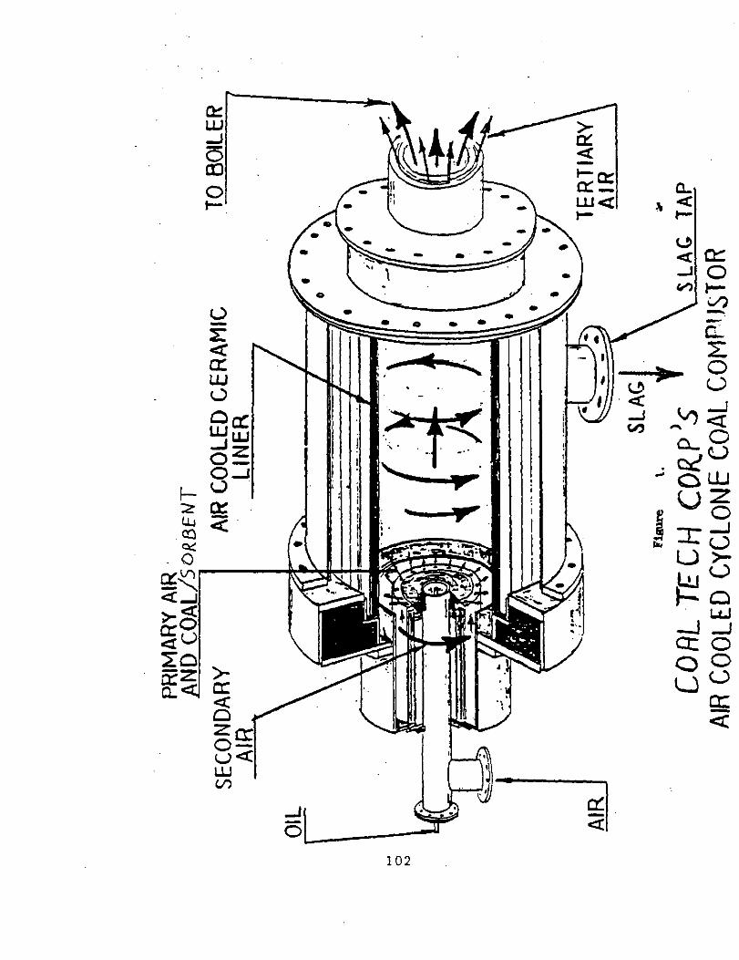
~Figure 1 is a schematic diagram of coal Tech'6 Advanced Air Cooled, Cy- clone, Coal Combustor. The cyclone comtxWor is a hi& temperature (,3000 F) device in which a hi& velocity swirling gas is used to lxlrn cru6hed or rulver- ized coal. The ash is separated from the,coal in liquid form on the cyclone comlxstor walls, from which it flow6 by gravity toward a psr-t located at the downstream end of the device. Coal Tech'6 cyclone.combustor is an advanced ver6ion Of COmJnercial Cyclone6 USed in large utility boiler6 in the IS50*6 and 60'6 (2). The use of these cyclones waereduced due to the high NOx emission6 re6ultif-g from their mode of operation.
A brief description of the operation of the air cooled comlxstor is as follows: a gas ixrner, located at the center of the closed end of the unit, is used a6 a pilot. A light oil gun, similarly located, ie then used to pre-heat the ceramic lined co&u&or wall and to start coal combustion. Ery pulverized coal (70% minus 200 mesh or finer) is transported by primary air (= or ( 2/l coal to air-mass ratio) and injected i&the comtistor through tubes in an annular region enclosing the gas and,oil burners. In a similar way. limestones or calcium hydrate powder for slag viscosity and/or 502 control is conveyed and injected into the comtustor. The comtxxtor can simultaneou6ly or separately fire all three fuels noted above; in addition coal water slurries can be fired if a slurry gun is installed in place of the oil gun.
Secondary air (SA) is used to adjust the overall combastor stoichiometry for So2 and NOx control. .Final or tertiary combxtion air is injectsd directly
into the boiler to establish overall stoichiometzy. The key novel feature of this cc&&or is the use of air ccolirx. This is accomplished by using a. ceramic liner, which is cooled by the SA and maintained at a temperature high enough to keep the 61ag in a liquid, free flowing state. The SA tangential injection velocity and the off-axis coal injection are designed to ensure quick and complete mixing of fuel and air, resulting in suspension turning of the coal particles near the cyclone wall with high cc&u&ion efficiency.
This arrangement also promotes slag retention, and value6 in eXce66 of 90% were achieved (3, 4) in the pilot scale,unit.while maximum value6 of 90% are obtained on Pc~with the present unit. This liquid slag is drained into a.water
21
quench tank where the solidified material is removed by a belt conveyor to a drum for subsequent disposal, a6 shown in figure 13. The balance of the slag/spent sorbent particulates, which are not retained in the comtxlstor or deposited in the bdiler,' are conveyed by the flue gases to a venturi type wet scrubber which remove6 sufficient particulate6 to meet emission requirements. This device is shown in figure 6.
Although the corn&&or is mostly air ccoled, some internal members are water cooled. This cooling water, as well a6 the slag quench water and the water discharged by the scrubber are all collected and dischargedto the sanitary drain6 at the test site. This water discharge .is routinely sampled
and analyzed for compliance with the thermal, suspended solids, and heavy metal trace element standards and.regulations of the William6poz-t Sanitary Authority.
Tests~on the combstir were performed in the boiler house of the Tampella/ Keeler Company in Williamsport, PA. and shown in figure 2. Installation work began in the Fall of 1986, and it was completed in March 1987. Figure 3 is a side view photograph of the com?xstor a6 it is currently attached to the boiler while figure 4 is a plot plan of the installation. Figure 5 is a process flow block diagram. ~
To contain the capital equipment costs at the comtustor site, it ~66
decided to sub-contract the'mlverization of the coal to a local vendor, who would deliver the coal to the site in a tanker truck. The latter acts as the primary on-site storage system, and it ha6 sufficient capacity for about 24 hr operation at full boiler load. To allow~6horter duration testing, and~to allow replacement of the empty trailer without combustor shutdown, a smaller 5 ton coalstora~e bin was.in&.alled at the site. to which coaliatraneferred from the trailer,~and from which it is metered to the combxtor by a pneumatic line.
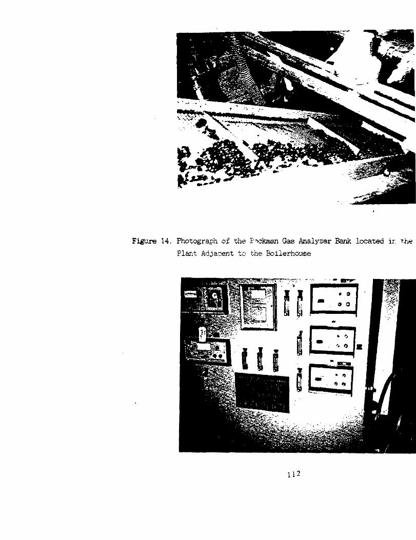
A6 noted in the Phase I 8ection, an existing gas sampling 6yatem in in adjacent building was uiade available for our use in this project. This system,
which ia pictured in figure 14. consi&ed of Beckman analv~er-6 for'02. CO, Go2. NCx, and 302. In Phase II, sampling lines were installed to allow extractive combustion gas 6amplin6 from either the boiler outlet. upstream of the Bcrub- ber, orfrom the 6crubber fan stack exhausting to atmosphere.
22
3.3.3. e
In the period between 12/87 and 5/99. 26 Phase III combustor tests were performed for a total operating time of around 800 hours, consuming about 125 tons of coal. All bat the last seven tests were nominally 24 hrs in duration, including heatup and cooldown on auxiliary fuek. The final series of tests was multi-day with overnight firing on pilot natural gas. The final four test6 involved three and four consecutive day operation. Most of the test goal6 wer? directed at optimization of comtu6tor and support equipment operation a6 well a6 developing the operational database associated with environmentally accept- able performance. The following sub-sections di6cuss these key issues on a topical basic. A chronological description of the test6 is pre6ented in Appen- dix I, while the compositions and properties of the CC&E and sorbents used are presented in Appendix V.
. 3.3.3.1. Solids
Problem6 encountered with solid6 feeding were either a total or partial loss of feed, or too much variability in the flow. Feed loss was~usually associated with hang-up of the pulverized coal or limestone (LS) in the feed hopper or 6crew, while diminished flow resulted from partial blockage of downstream flow components. In addition, the presence of oversized "tramp" material. such a6 rocks, can lead not only to flow problems tit also to equimnt damage, which occurred on one occasion. The hang-up problem wa6 overcome by adding vibrator6 on the hopper6 and by rearranging the pneumatic PiMmz The first occurrence of the "tramp" material problem wa6 associated with improper quality control at the subcontractor's Pulverisation site. The 6eCOnd occurrence involved metal nodules, which were attrilxztable to inadequate quality control at the pllverization company.
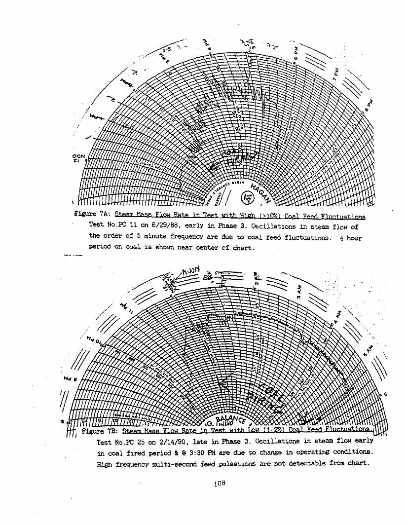
Variability or oscillation in 6olidS flow; which for coalzhad a sine wave
period on the order of several minutes, usually resulted from excessive interac- tion between the coal feed and pneumatic conveying SYStem. The problem was greatly reduced by testing various arrangement6 of the yneumatic lines. By early 1989, the oscillations ,in the coal flow were reduced from a high of 17% tolti3%. Fuel rich operation below 90% of theoretical combustion air CSR (0.9). which is necessary for both NOx and SO2 control. only‘~becarne possible
23
when these fluctuation6 had been essentially eliminated. Since the boiler acts as a CalOriJI&er lOW fEqUenCY COal.feedflUCtuatiOn6 can be seen on the steam flow chart records.. F-e 7 6hOWS the steam flow chart6 for two coal fired te6t.s. Figure .7a was obtained during a test early in the Project; while the: figUre 7b wa6 taken later in the project after the feed fluctuation problem had been solved. Note that strong fluctuations in the steam flow rate inthe top chart compared ,to the 611~0th ste6mflow in the bottom chart.
Air/coal mixing is critical to proPer combxxtion. It was determined that central pintle injection of the coal resulted in poorer mixing than off-a&, injection. However, even with off-axis injection,, non-Uniform or irremlar coal flow,can result in flame Pulsation with fluctuation6 in flame length of, several feet and frequencies in the seconds range. In this situation. efficient combustion within the combu6tor is not achieved.
: However, even with Uniform off-axis coal injection, initial dry PC testing yielded cwnkxxtion efficiencies of 80% or less. Thi.6 problem was SOlVed bY providing sufficient combJ&.or heatup prior to coal injection. This was accom- Pli6,hed by the addition of a hi& thermal inPut oil~sun which was u6ed to heat the walls to temperatures at which the nominal slag viscosity was 250 poise or le66. .he ti the P3fraCtOZ-Y n&U'E Of the ash for 606t Of the PeIIIISylVatIia..
bituminous coals used in the project, it was necessary to flux the ash with .the injection of limestone or calcium hydrate. These measures also improved combxtion efficiency, resulting in efficiencies averming 97% and 94%; based on slag carbon and stack gaS/ParticUlatB analysis, respectively, since test S of May, 1986.
As can bs seen from Appendix V, coal Particle size was not varied greatly and therefore had little impact on test obeervablea. However, work performed under other PrOjeCtB SuBBeStS that overall COmtNStiOn efficiency i6 enhanced by having a finersized coal.
.' : 3.3.~3.2. Air .,
The original liner material in6talled in the comtustorwas determined to have thermal Properties that were inconsistent with the,hi&lY refractory coal aghea, and correspondingly hi& slag ,fluid temP6ratures. enrployed in the early
24
tests. In addition, chemical analysis ,of slag samples obtained during this testing period showed evidence of slag/liner 'chemical interaction.~ Initial attempts to achieve good slagging conditions with this liner resulted in ovsr- heatingof the liner and partial refractory failure. This oxurred early in Phase III, land the combustor was disassembled and a new liner material, which was more compatible with the specific test coals, was selected and installed. As part of this redesign effort, sections of the ceramic and metal wall materi- al was submitted by DoE/FZIC to the Cak Ridge National Materials Laboratory and by Coal Tech to Professor D. Simpson of the Lehigh University Geology Depart- ment for electronmicroprobe and X-ray probs analysis. The results showed that while slag attack of the wall materials use taking pla&. this was not the probable cause of the wall failure. Instead it appeared tbhave been caused by failure of the support structure of the.ceramic wall. This hypothesis was strengthened by a stress analysis of the'&mbustorwall performed by Professor P.V. McLaughlin of Villanova's Mechanical hgineering Department. It showed that the suppOrt structure was subject to high thermal stresses. These,rssults tire incorporated in a modified support structure forthe comtustor wall.
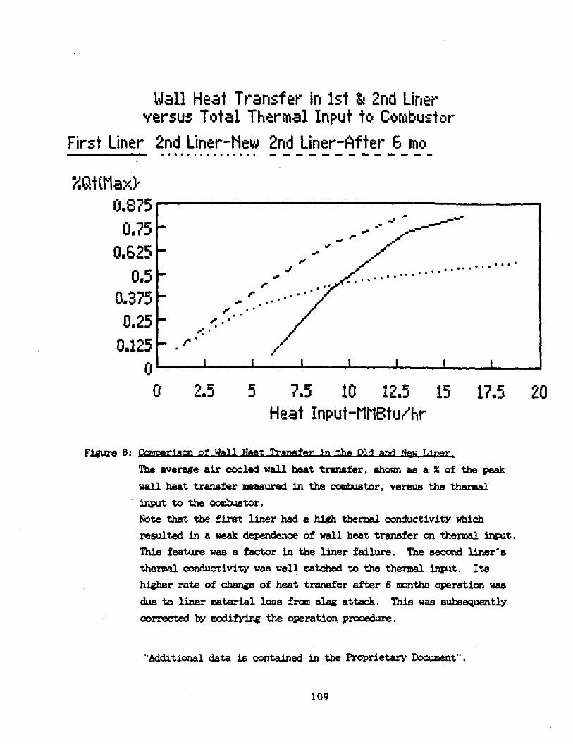
In addition; an upgradedcomtustor operating procedure, which relied on improved prccess 'temperature measursmsntandcontrol, was implemented. This procedure was designed to limit thermal shcck of the refractory as well as to minimise slag corrosion.' The new liner and control strategy were implemented during tests 8 and 9 in May of 1988. and have proved to bs very satisfactory. Between 800 and 850 oft the nearly 1000 hours of comlxstor operation, since the start of the Clean Coal tests, have been performed with the new liner, without having to replace it. Figure 8 shows the different nature of the wall heat transfer in the new liner ccmpared to the old liner. The new liner is much. less dependent on total thermal inrut to ,the comb-&or.
However, it,should be noted that the present combstorwas operated under a harsher thexmalenvizunmentthan conmisrcialslagging comtustors due to daily. thermal cycling, an@ due to the wide range of operating conditions experienced ,during the parametric test effort. In commercial units; the combustor is only shutdown for maintenance after a relatively long campaign, at which time the refractory is.generally replaced. As ,a result, in the present combustor, loqa- lized refractory losses were experienced from time to tims but were quickly re- paired with chemically identical cement. As cyclic operation generally occurs
25
occurs in smaller industrial and coarnercial boilers, a means had to.be deve- loped to replenish the refractory wall during comb&or operation.' A procedure to accomplish this, which.involved adjusting process tempsratureand slag laver thickness, was developed late in Phase III testing. This procedure had been further refined in postCleanCoalpro.iecttests, andno patching of the comkus- tor wall has been necessary since the early Spring of 1990.
..3.3.3.3. CombustAr/Boiler
A major operational difficulty encountered during the Phase III testing was refractory failure inthe exit nozzle section, at its attachment pointto the toiler. The exit nozzle section connects the comb&or to the boiler. In September of 1988, during test 14, hot comktion gases vented out of the boiler through small openings in the boiler aozess dcor. Post test inspection revealed extensive damage tothe boiler front wall. Howwer, the refractory in the exit nozzle was not damaged, and it indeed survived the entire 900 hours of operation. Detailed mechanical and heat transfer analysis led to the conclu- sion that the failure occurred mainly due to inadequate insulation at the nozzle/boiler interface.. A different installation design, using different refractory materials, we implemented and has performed 6atisfactorily.
A second area of difficulty was overheating at the comb&or/exit nozzle thermal interface. While temporarvsolutions controlled the problem initially, it was decided in the Sunnner of 1989 to design and install a modifisd interface refractory the next time the problem reappeared. This did not,occur until. February 1990, after about 250 to 300 hours of operation. Since the ccmb&.or was being used for testing under-other projects, the modification was imple- mented in two steps in Mamh and June 1990. In recent tests, the modification has performed as per design. Nevertheless, thermal data show that a modest degree ~of.additional cooling is required at the boiler front wall in order to allow round-the-clock operation-at full thermal comtxzstor load.
Cne,final point~of importance regarding the operation of this comi&tor is 61&x flow into the toiler. Depending on the cantxuxtnr’s operating conditions. and on ,the geometry and contour of the exitnozzle. it is possible~ to either close a major part of the exit nozzle with slag, or to alternatively produce significantslag flow onto the boiler furnace floor. This ccanplex issue was
26
investigated in'detail during the test effort, and procedures to prevent exit nozzle~closing or slag flow into the boiler were developed.
3.3.3.4. Slae
As not& in a previous section, initial testinz on dry FC resulted in pzor combustion efficiency and,slagging due to the high viscosity of the slag. It wae not until L3 injection was routinely implemented that both combustion effi- ciency and elsg retention/rejection were greatly improved. In addition, plug- ging of the slag tap was the primary cause of premature termination of coal fired operation early in the Phase III testing. On one occasion, operation con- tinued with a closed tap. After the test, a one foot thick layer of frozen slag covered the combustor'floor. After many modifications to the slag tap operation, a combined mechanical and tap heating procedure wae developed to keep the slag tap open. This procedure was introduced in mid 1989, and since thattimsonly one test wss terminated due to slag tap plugging. 'After the modifications were finalized, slag retention in the combustor. exit nozzle, and rejection to the slag quench tenk averaged 72% with a range of 55% to 99%. ,Un- der near etoichiometric conditions, the comtietor/boiler retention was better., averaging about 80% with a range of 65% to 96%. The slag retention is very sensitive to the injection location. After the completion of the Clean Coal project a new and improved solids in&&ion procedure was used for fly ash injection. In one test better that 86% slag retention in the comtustor was measured from the slag paseirg through the slag tap in the combustor.
3.3.3.5. E
The combustor was controlled manually for virtually all of the coal fired Clean Coal Tech.nolc& testing/The original test plan called for overnight , shutdoun of the combtorwith daytime coal fired operation: This was dictated by project resource limitations. However, as it beams clear that heatup and cooldown of the comtustor could not bs implemented with coal firing. and that cold-start daytime heatup and cooldownwastedtoo wtch opsratingtime, the con- trol system was converted to automatic overnight operation on low firewith pilot natural gas at the bsginning of 1989. This operational and safety inter lock system was devised and implemented to permit unattended overnight firing. This allowed a more rapid start-up the next day. which resulted in more test
27
timeon coal, and also allowed round-the-clock operation. This, procedure has worked well, and five four-davteets with round-the-clock oreration. were loaxed since that time.
Dx-ins the Spring of 1990, sufficient operational data had.been acoumula- .ted to implement comrxlter controlled operation. Under another pro.iect, a,
commercial prccess control software wckage was 9tomized for control of the air cooled combustor using,the control strategy developed during Fhase.111. This system was installed prior to the final four-day Clean Coal test in Ma!, of 1990. It is currently undergoti.shakedown as part of,other test efforts. This system is very impxtent to the commercial success of the combustor, as .it will allow automatic combustor operation with minimum supervision. .This, is ~. critical in small boiler .ayplications., Since May 199O;..the computer system has been,used to control the combustor operation.uith manual control inputs. In addition. more and more comlxlstor control functions are beins automated in each eucceedti test. The ,objective ie,to achieve completelv,automated combustor operation.
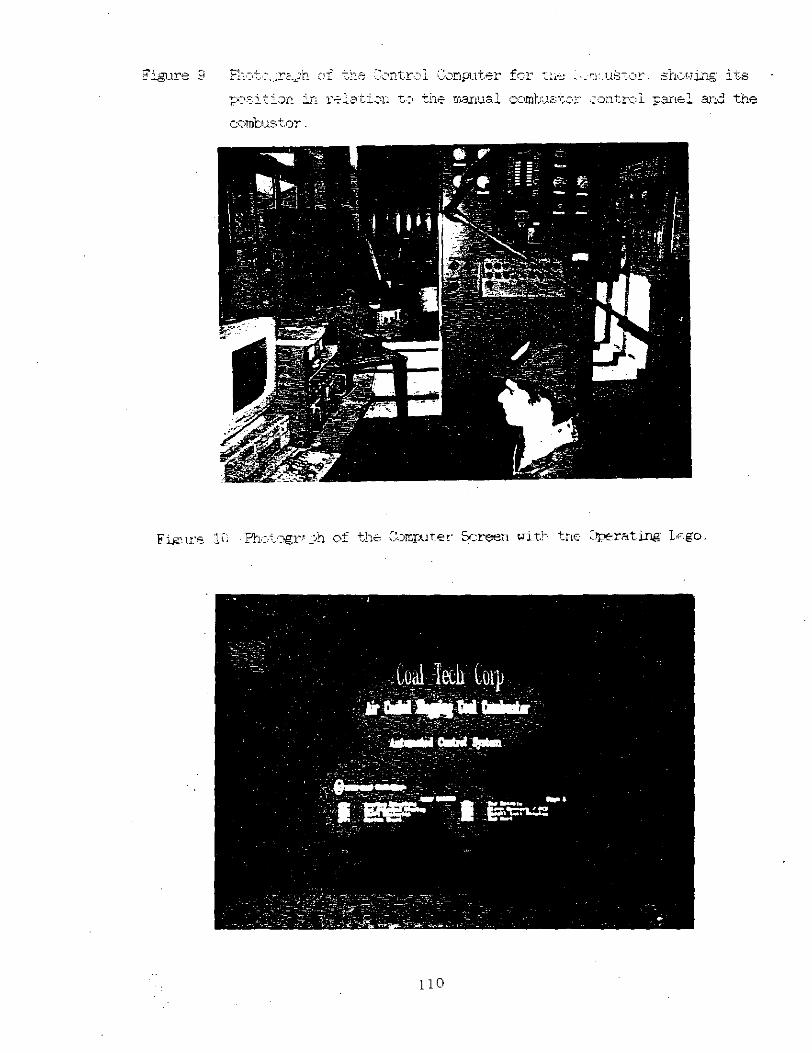
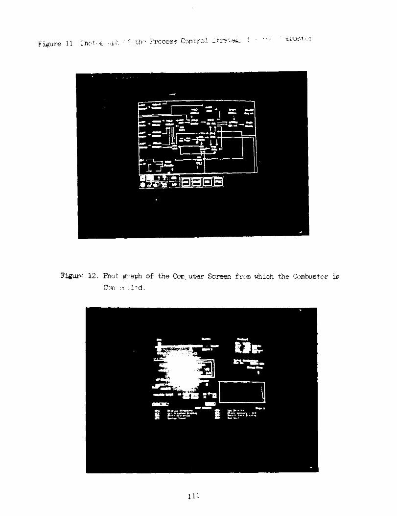
Figure 9 shows the.location of the computer relative to the computer and manual oontrol,panel. Figure 10 ,shows the pmpxter screen with the Coal Tech operatinslogo.. Figure 11 shows a sample~contryol,strat.egy for the combustor. Figure 12 shows the computer screen of the combxtor control sequence.
3.3.3.6. Miscellaneous
I&-b shakedown testing of the system; .excessive noise and vibration from the hi& pressure ccoling/cc&xstion air fan was noted. Althou& not strictly a compliance problem, the noise level was a,considerable nuisance. After exten- sive consultations with the manufacturer, the problem was discovered to be main- ,ly caused by a design defect in ,which the fan operated in the surge mcde to the mint where damagetothe fanhousing 8uppxt.s occurred. CoalTechdeviseda temporary method of operating the.fan which eliminated the surge. but the pro- blem was not fully solved until the fan was returned to the manufacturer for rebuilding. The rebuilt fan was installed during the combustor refurbishment, and it now operates satisfactorily at a noise level far below that of other equipment at the test site.
28
Althoughthe scrubber has probably been the most reliable conmercially installed handwane cxxnrment of the entire system. there were three occasions when it nesdsd repair, all in the second half of Phase 3. The first occasion involved replacing a section of the cyclone wall where it had been worn by solids ~abrasion. In order to minimize the scrubber cost and in view of the limited lifetime required for this ecuiment. a low cost and thin wall sectioh had besn originally installsd. A heavier gage. abrasion resistant steel patch was installed to repair this section: The sscond repair involved replacins the scrubber fan owing to imbalance which was most probably caused by scrap matsri- al relsased during the scrubber wall failure. The imbdance loosened the fan bearings. The scrap metal also dams@ the stack damper outlet used to mcdu-
late the fan. The third incident was related to the first; in that a side panel of the scrubbsr inlet developed a shear tear, which was probably caused by the stress induced by the 'first repair. This section was provided with added supports to reduce the shear load. To prevent future fan and scrubber vessel problems. a procedure was im~lemnted to clean the scmbber,fan and scrubber tilet after each test.
Two pin-hole leaks in the water cooled lmrner developed during Phase III. These Leaks had non adverse effect on operation and were fixed between test nrs.
29
3i3.4. &.&d&&E .~.
In this section the technical results are presented by specific topic, and categorized as either a comtustor or an environmsntal performance observable. Combustor performance refers to oneration of the unit as a burner and thermal process device. Here, specific observables~include combtion efficiency or fuel utilization, thermal characteristics such as heat release and operating temperature; slag retention/rejection. and refractory wear. Environmental parfomance deals with project goals in the environmentalcontrolarea, addressing NC% and Sax reduction as well as slag reactivity. In addition, results of regulatory compliance testing for particulate6 and wastewater are included.
In an attempt to unravel the complex interactions of comtustor operating conditions on test obeervables, the Coal Tech Clean Coal data bsse, supple- mented by the DOE and EPA ash conversion data .wassubjscted to statistical analysis. The extensive data base consisted of a matrix sired 207 X 45, i.e.~ there were 207 separate test conditions, each having up to 45 different obaer- vations or measurements. Thus the matrix potentially consisted of over 9000 entries. However, in many cases certain measurements were not always taken so that the actual data base consisted of about 6500 entries. It should be noted that the Clean Coal data base did not include teats with the initial liner since mostofthatdatawas obtained in preliminary testing, where combustion efficiency and slagging were very poor snd, in any case, the recorded date were not as comprehensive as with ths new liner. Thus, all statistical ,results are for the new liner only.
After evaluating hundreds of models, it was determined that all key process observable6 could be adequately aocounted for by models having four independent variables, namely, first stage inverse equivalence ratio (SRI), combustion swirl air pressure WIFWR in inches of water column or "WC), total fuel heat inplt (HEATIN in MMStWhrl, and percent contribtion of coal to the total heat inwt EcrFc). In addition, models of the sulfur related independent variables included the C&S mole ratio (CASRAT). It is important to note that all exneri- mental obeervables or dependent variables, including measured SC2 reduction in the boiler outlet (SEMIBO), providsdindependent variable or operating params- ter models having a lou(< .05) probability (two-tailed significance) of zero
30
cosfficient. This suggests that the measured changes in test observables. as a function of parametric operation, were in fact due to changes in operating conditions and not simply random events.~
It should bs emnhasized that the statistical method, while useful in &au& ins relative effects at'averase conditions, is less useful, and may even bs q islsading, in predictins the true or actually measured ranse.of values for the various dependent variables. This resides in the fact that model predicted 'values used in this analysis are based on the full range of one independent variable plus the average values for the other independent variables in the model. In 'actual operation. the negative effects of one of the process,vari- ables on good operation were orxlinaril~ compensated for by varying other wra- meters, usually away from their average values.
In the following subsections a brief technical description of the relevant physical and chemical processes is first pressnted as ba&round. Follows this, the test results ars presented and discussed. Key results from the statistical analysis are also included; however, a detailed presentation of the statistical analysis is found in Appendix II:
3.3.4’.1. ‘Combustor
. . 3.3.4.1.1. CambustiMl
Coal combustion msv~bs thoughtof as cccurring in two steps: couhstion of volatilss followed by char turnout. Under oxidizing (fuel-lean) conditions the nnjor products of combustion GlX'sl are CO2. H20, N2, and 02 with small amounts ofc0, NOx, and SO2 depending on exact fuel composition and details of the wmtustion ptccess. With reducing conditions, as would beencountered in fuel-rich staging. the char residue is gasifiedby endothermic reactions with. the CO2 and H20 produced from "normal" combustion: Hers the major Rx.6 are CO2, CO, H20, H2, and N2 along with some unburned hydrocarbons (UHC) and other reduced species.
he efficiency of this carbon conversion or utilisation ~mcess depends on temperature, residence time, and stoichiomstrv as well as char particle size. In addition,~ chsr not converted in the fuel-rich first stagema~ be consumed if
31
it is carried over to the second, excess air stage, resulting ingcodoverall comtustion efficiency. Even with less thsn 100 % carbon conversion or char turnout in the fuel rich first stage. both the coal sulfur and nitrogen are essentially completely evolved if they are organically bound (5). .However. this conclusion doss not apply to coals with high inorganic sulfur or nitrogen.
Shakedown testing of the system was conducted with coal-water slurry (CNS'P and resulted in near 100% fuel utilization based on measured CWS and air flows plus stack gas combustion product analysis. Initial dry coal,t.esting. however, resulted in estimated combustion efficiencies < 80 %. as already noted. To see if coal/air mixing was playing a role, coal injection geomstry was ucdifisd with inconclusive results. Efforts were then directed to providingsufficient comhstor preheat prior to coal injection. This required installation of a high thermal input light oil gun. The initial results of this effort were still poor.
Evaluation of the coal chemical composition show4 low volatile matter (VW and an extremely refractory ash, having a T-250 of about 2800 F. It should be noted that the poor combustion characteristics ,of the coal were simultaneously related topoor slagging and high solids carryover into the boiler. With these apparently related results in mind, limestone in&action was tried to flux the ash. The results were greatly improved slagging, which will be discussed in more detail later, and an improved combustion efficiency estimate of = or > 95 %. This encouraging result was obtained by the fourth Kase III tsstand was subsequently improved with higher VM and less refractory ash coals to yield overall coal combustion efficiencies, during steady state opsration, of 95 to. 99 %, based on stack gas, slag carbon, and scrubber particulate analysis.
Testing aimed at fuel-rich comtitor operation to optimise Nox and,S02 control was initially plagued by poor overall carbon hunout. However, ,reconfiguration of the Tertiary Air piping, leading to improved fuel/air mixing in the comb&ion second stage within the boiler, allowed fuel-rich comtustor operation (0.7 inverse equivalence ratio).with gocd overall combustion efficiency.
However, recent (post Clean Coal Technology project1 tests have shown that, previcusly undetected coal feed induced non-uniformities produce multi-second.
32
flame pulsations even at fuel.lean conditions inthe combustor. .These ,Fulsa- tions wculd, have had aneven greater adverse impact on the local fuel burnout in the combustor under fuel rich conditions. This in turn would adversely affect prccssses such as sulfur.capture in the combustor. The feed fluctua- tions have,bsen very recently greatly reduced by reconfiguring the coal feed. It is, therefore, essential that fuel rich combustor tests, including sulfur capture tests, be rereated under the new fuel fesd conditions.
In the statistical analysis there were three independent methods ~to assess the degreeof fuel utilization or combustion efficiency as a percent of total. combustibles: slag carbon content (SLAGCRFF). msasured air and fuel flows vs.- &a&oxygen ( GASXFE'l, and carton content of the solids discharged by the scrubber (TSSCRFF). These values are expressed as percent conversion of fuel combustibles to final products. SLAGCEFF (slag carbon combustion efficiency)' relates directly to the comb&or's operation, which includes fuel rich conditions, while the other two relate to overall efficiency, including second stage combustion with excess air. In percent units, the average measured value, standard deviation, plus high and low values for each of these variables is: SL&CEl?F (slag carbon combustion efficiency): 99.8, 0.7, 100.01 95.0; GASCRFF (~flow and oxygen com&stion efficiency): 107.0, 9.0, 135.0. 81.0: TSS!XF (scrubber carbon comb&ion efficiency): 94.4, 3.8. 99.8, 90.8.
Based on' statistical model&!, the dependence of each combustion efficiency variable on key operating! parameters was determined. Although each.of the .' combustion efficiency variables depends on several operating parameters, the relative effects vary.
All three combustion efficiencies increased as SRI (first stage inverse equivalence, ratio):increased, which is expected on the basis, of imp?ovsd.com~- tion at stoichiomstric and low excess air conditions. " The effect of.SRl (first stage inverse equivalence ratio) is nearly equal for all three combustion. effi- ciency variables. Combustion air swirl pressure (SWIRLPR) ,had a small effect, on combustion efficiency with all three combustion efficiencies decreasing as air swirl pressure was increased. This effect is likely due to increased liner surface cooling at higher swirl pressure. This phenomenon had been obeervedon several occasions. This cooling probably results in partial quenching of the wall coal turning reactions, especially at.low SRl (first stage inverse equiva-
33
lence ratio) where endothermic char gasification reactions mu& proosedto com- pletion to obtain good fuel utilisation and/or com!aW.ion efficiencies.:, All combustion efficiencies increased as fuel heat-input increased.-. This effect is probably attributable to increased combustion intensity at higher firing rates, resulting in improved fuel utilization. . .
The psrcsntof fuel heat input due to coal (PcTpc) effects indicated that all combustion efficiencies increased as the percent of coal firing increased. At first glance, this appears to be unexpected since coal is more difficultto bum than natural gas or light oil, the auxiliary fuels used in -the tests: However, as PCPK (percent coal firing) incrsases, the percent of,auxiliary fuel decreases and there is therefore less coetition for oxygen from the premium fuels, and coal combustion can proceed to .a greater extent. In addition, and probably more importantly, coal char com&stion/gasification takes place to soms extent in the oombustor wall slag layer. As FClX (par-cent coal firing) gce6 up, there is relatively more coal ash/slag in which the char particles can be embedded for subsequent reaction via gas scrubbing. This, interpretation is supported by testing in early Fhase III, which showed that the presence of a liquid combuator wall slag layerwas ,nscessary to snsure gcod coal comtition.
Unlike SRl (first stage inverse equivalence ratio), SWIRLPR (swirl air pressure). and REATIN (total fuel heat input). the effect of KXFC (percent coal firing) on the three comhstion efficiency variables is not of comparable msgnitude. This is illustrated in figure 15. PClTC (percent coalfiring) apxzeam to affect SLAWRFF (slag carbon combustion efficiency) about twice as much as 'CWCEFF (flow and oxygsn combtion efficiency) or TSSXFF (scrubber carbon combustion efficiency). This is not unexpected inasmuchaathe latter two variables are measures of overall combustion efficiency and thus include the effects of second stage hunout, which always.takes place under,excess air conditions. SLAGCRFF (slag carbon combustion efficiency)., .however. includes fuel rich combustion and would therefore bs mope susceptible to the oxygen' competition and wall,tuming effects of FCEC ksrcent~ccal~firing1 than the, other variables.
In conclusion,,the present project achievsd many of the technical goals repuired to demonstrate co-r&al readiness of,this technology for boiler
34
retrofit applications. Odimization of combustor oRration in a safe and efficient mode, which was a n&or goal%of the testpiogram, was generally achieved. A key element in reaching this goal was achieving m&r 100% overall comtition efficiency. It should be emphasized that the ultimate success in ~area~uiredsimultaneous~mvementincombustorslagping,aswellas proper ~mces6 temperature control. The latter optimisation was achiwed by flexibilityprovided by comtustor air cooling. and its effects on wall tempera- ture control; Air cooling was decisive in achieving not only.good.comtition efficiency but also enhanced operation and control in other areas as will be discussed later. Attaining high levels of comb&ion efficiency with a.wide variety of coals, under bath oxidizing and reducing conditions. was therefore a major accomplishment of this project.
3.3.4.1.2. m
Actual combustoroperating temperature was determined by three experimental observables. Thecalculatedliner surface temperature (LIREXl'ENl. dsgrees F, is an indicator of the combustorwalltemperature. The ccmbustorcooling air tube-hot-side temparaturs CTRSTBP), degrees F, is a directly measured variable whichrelates to the amountofheatbsinggenerat-ad in and extracted fromthe comhastor . Finally. the wall heat flux in Btu/hr/ft2, as calculated from the cooling air flow and delta-T (AIRRLUX), is an overall measure of the thermal interactimbetweenthe hotcomtuEtiong55e5 and the comhstor wall *.
Basically. process Mnparatute variables are affected by the 6ame indepen- dent variables. and to the 6ams degree, as the comtition efficiency variables. This isto be expected, since good combustion is associated withhigh heat release.
Statistical analysis of the effectsof SRl (first stage inverse equivalence ratio) on the three process teagerature variables showed that all temperature indicatcrs increassd as SRl (first stage inverse squivalence ratio) increased, which is expscted on 'the basis of improved combustion efficiencyand/or heat release at stoichiometric and low excess air conditions. This effect is natu-
(*I-"Added thermal parformancs data is contained in the Proprietary Document". 35
rally coupled to the effect of SRl (first stage ,inverse equivalenceratio) q combustion efficiency discussed above. The effect of SRJ (,fir+ stage inverse equivalence ratio) is nearly equal for LINERTEB komtmtor wall temperatq-eJ and TRSTEMP ~(air cooling tube temperature) but considerably less for AI&.@ (wall heat trksfer). This difference,is probably due to the fact that,AIP@LUX (wall heattransfer) is a measurement intesrqti over the entire comb.ztor wall surface, including boththe relatively cool mixing zone as well as then main flame or conkustion7,one. The other two measureren ts are localizedto the downstream side of the comtustor where the main flame zone is.lcxated. Peak flame temperatures strongly depend on SRl (first stage inverse equivalence ratio)? so that flame zone wall t.emperaturemaaaumments are expected to be highly influenced. Alternatively. integrated or averaged wall thermal effect+ would tend to smooth out this SRl (first stage inverse equivalence ratio) effect due to combustor geometry effects on radiative heat transfer.
Analvsis of comtustor circumferential and.axial wall thermocouple (TC) .' temperature meas uremsnts, made in early Phase III testing (March; 19881. showed that comkustor~heat release was essentially radially uniform but axially non- uniform. Excluding the exit nozzle, approximately the first one-third of the comtustor served as an air/fuel/sorbent mixing zone and had a'relatively low temperature, accountini.for less than 30% of the heat release, while,the,r&t. of the combustor had higher temperatureand heat release; It should be em&a- sized that these meas urements reflect the smoothing effect of radiative heat transfer, so that the actual differences in comtx&or zone gas temperatures are probably much greater than those suggested by the wall TC measurements.
Comb-&ion swirl air pressure (SWIRlPR) effects on LINERIB (combustor wall ~rature),~THSlDlP (air cooling tubs temperature), and AIRE'LUX (wall heat transfer) were small*. Analysis of fuel heat input UIEATIN).effects indiated that all process~temparatures increased aa fuel heat input increased. This effect is attributable to increased combustion intensity at higher firing rates, resulting in'higher heat release.'. The effect of RRATIN (total fuel heat kwt)~ is about the sams~.for all three process temperaturevariables. The pscentof fuelheat i.np& due to ccal (PGPPC) caused all process temperature
iridicatorsta increase as t.he.percentof coal firing increased. This effect is nodoubt ccnapled to improved combustion efficiencv at higher PGTE (percent.
(*)"Added thermal performance data is contained inthe Proprietary Document". 36
coal firing) as already noted. However, the relative effect is. larger for, pro&s temperature than for comtuetion efficiency. This is probably attri- butable'to enhanced wall heat transfer as PCI'FC (percent coal firing) in- creases, owing to its higher flame emissivity ~8. oil & natural gas (ffi~). and the effects of wall'bumin43. The effect of PCl'FC (percent coal firing) on the pmce6s temperature variables is essentially the same for LINERI'Dl (cdmtxstor wall~.temperature) and THSTEW (air cooling tube t.empePature). hat is.somewhat
higher for AMF'LUX (wall heat transfer). Figure 16 illustrates the effect of HEATIN (total fuel heat inrut) on wa&flux for coal and oil firing.
In, addition to operating temperature, thermal performance includes the corn-- tustor's efficiency a6 a tumer.or combustion chamber.' This aspect ha6 already been discussed in the preceding section. It also refers to the combztor as pat-t of an overall sy&em, namely, a6 a heat source for a package boiler. In this regard, effects of the combu6tor on prccess efficiency are imgortant. Un- like water cooled comk&ors, the preesent air cooled unit recoverscomtustor en- thalw as regenerative air preheat, resulting in combastion air temperatures of between 300 and 500 F. Minimal water ccoling to comkxMzor component6 resulted in &manent heat losses of only 2 to 3% of total heat input. Thus recovery and direct utilization of combustor thermal energy is one significant advantage of the Coal Tech airccolins.concept as compar& to water cooled units. In the latter. water coolti energy is low grade heat that cannot be efficiently uti- lised in a power cycle.
Another advantage is the high level of flexibility that air cooling pro- vides with regard to tailoring wall temperatures.for efficient combustion and slagging. This permits operation over a.wide range of conditions [e.g. SRl (first stage inverse equivalence ratio), HEATIN (total fuel heat tit)] for a variety of fuel6 which would not have been attainable.with water cooline. This flexibility is a major plus in spin-off applications such as incineration and. vitrification of environmsntally active solids. Furthemore, the integrity of air cooling proved to bs far superior to water cooling. Namely, even with par- tial.failure of the first liner and nerforation of soms of the cooling tubes,, the unit was still operable such that it could be shut down in .a safe and gradu- al manner. 'Thi6 is important since with water cooling, a'water tubs failure of similar siegnitude would have resulted in immediate shutdown and additional re- fractory damage owing to thenoal shock, as well as possible system over-pressure
37
due to steam generation., Thus the potential for catastrophic cooli.~ failure is much less with air than with water; an imp&ant consideration in a conmerci- al process application.
Another impytsnt as- of thermal performance is boiler derating, which is almost always required with retrofit of conventional FC turners to oil fired boilers. In the ClssnCoal~ test program, with the comtustor itself acting as a combustion zone, there was no evidence of,flame impingement or boiler tube ero- sion/corrosion inthe fir&ox, even with staged combztion. However, dry ash deposits did form on the boiler tubes. They were easily brushed off, and soot blowing and/or.ms&nical.tube cleand must be an integral part of the mainte- nance schedule for a commercial boiler using this comtustor. There was not sufficient operating t&e to establish a tube cleaning maintenance schedule.
3.3.4.1.3. m
In general, efficient operation of the slaggins prccess resuires rapid re- moval of the slag-from the combustor. To achieve rapid slag floyrequires a
relatively low slag viscosity, .generally below60 poise (61 and possibly consi- derably lower (71. The viscosity,of coal slags ~depends on comwition and temperature. Highly acidic (high silica or alumina content) or highly basic (high iron, calcium, or magnesiumoxide content) slags have hi& melting points or equivalently high relative viscosities. Numrou~ studies,to measure the viscosity of coal slags and to correlate the viscosity to the slag composition have generally indicated that most coal,slags will have the Fesuiredviscosity for r&id slag flow in the temperature range of 22OO.t.o 2700 F.
Wing to materials durability and other process constraints such as minimi- zation of trace metal vaporization, it is usually not advisable to operate a slagging unit above about 2400 to 2500 F wall temperature, i.e. a key require- ment is to provide a slag with a.low enough viscosity to flow at about 2500 ;' in the combastor.-.-In cases of highly refractor-v, acidic coal ash it is known that additions of a fluxing sBent such as calcium oxide (CaO), usually intro- duced as limestone (C&03), which quickly calcinss to CaO, will produce a slag having decreased fluid temperature and viscosity. A6 noted in a previo<= sec- tion, initial testing on dry PC resulted in poor combustion efficiency and slagging due ~to the high viscosity of the slag. It wea not until limsstone
38
(LS) injection was routinely implemented that both combustion efficiency and slag retention/rejection were greatly improved.
Of the total solid6 injected into the combustor, which include coal, sor- bent, and, -on occasion, fly ash, various percentages of the non-combustible and/or non-volatile solids report as slag rejected by the comtustor (SLAGREJ). a6 boiler de&vsits (BoILR&?). a6 scrubber Solid6 (SCRtlRREJ). and a6 atmospheric emissions. In a separate D3E SSIR nroject, aimed at evaluating the feasibility of converting utility fly ash to an environmentally inert slag, using the Coal, Tech combustor. non-isokinetic particulate sampling of the atmospheric dis- charge, downstream of the scrubber, was performed. Results of these prelimi- nary measurements showed that with coal firing (HRATIN, total fuel heat input. q 10.6 KMStu/hr; FCTFC, percent coal firing, = 75%), plus combustor sorbent and fly ash injection (0 to 150 PPH). the solids discharged to atmosphere accounted for about 0.5 to 3% of the total solid6 input. This relatively small amount was neglected in the,present bulk solids distribution analysis.
SLAGREJ (co&u&or tap sl6~ rejsction) is actually a lower limit on combus- tar slag retention since the measurement only cccasionally included slag inven- toriedin the comtustorand exit nozzle and basically was only the slag rejec- tedthroughthetap. In our assessment, the slag depositing in the exit nos- zle, and flowing onto the boiler front wall and hearth. should be con6idered a6 part of the ccmbustor slag. This ie especially important at high coal fire, when .there can be large.slag deposits in the exit nozzle. since this, material can rarely backflow into the combustor and be rejectedthrough the tap. Hou- ever, in practice, ,this material was seldom included in the SLAGREJ (comtqetor tap slag rejection) meas urement since retrieval of this slag required consider- able effort and downtime. Thus, in the statistical analysis, this slag was included as BOILRRJ (boiler solids retention) by default. (In recent post Clean Coal,project tests, very high .a6h injection levels have been utilized to thepointwhere inventoried slag/ash in the boiler is being recovered after each one day test.. These recent result6 show that slag rejection i6 better than the levels reported for the Clean Coal project. 1
An examination of factors leading to exit nozzle slag buildup is relevant to this section. Exit nozzle slagging can occur either as an greet in opera- tion or as a normal adjunct to operation at moderate to high fire. Upset exit
39
nozzle slag buildup/blockage has two requirements: (11 poor slagging in the com- bustor; and 12), a hot exit nozzle. ,The foci resuiremsnt is usually accom-: par&d by poor combustion as evidenced by "char balls" in the rejected slag. Poor sl&ing/com~tion occurs when the ash/slag is not tacky or sticky so that injected solids tend not ,to be trapped on the conitustor wall but are carried out to the exit nozzle. Since the exit nozzle is almost always hotter than the cc&u&or, due to heavier insulation and the lack of active cooling. slagging occurs here with buildup and potential blockwe, or with sla$flou into the boiler.
Conditions in the combustor itself, which are not conducive to gcod slap- gins/combustion can arise if (11 the combustor is too cold; (2) the flame tempe- rature is too low; or (3) the slag T-250 is too high. The first case occurs when the comtitor is cooled too muchor if the switch-over from oil to coal is premature. The second condition occurs when SRl (first stage inverse tiuiva- lence ratio) is too low (< 0.61 or too hi& (>1.5 as per test FA4 of the DOE SBIR project), in which cases ,thers is poor heat release to the comtustor due to incomplete combustion or excessive flame cooling, respectively.. Thus the interplay of these thres factors can account for poor slagging/corotition as well as exit nozzle slag buildup. As noted above. there is aLao& alwavs'scme nozzle slagging at moderate to hi& firs owing to direct flame impingement.
One finalpointon this subject is thatovernightheatingof the combastor, even at low levels, revealed that the refractory insulated exit nozzle, unlike the air cooled co&u&or, runs near-adiabatic, retaining much of its thermal storage. This resulted in initiation &slag formation in the exit nozzle, probably in addition to comb&or wall slagging. This was not evident during the one-day parametric tests. &pending on ,the com~stor's operating condi- tions. and on the geunetry and contour of the exit nozzle, 'It is possible to either close a major ~&art of the exit nozzle with slag, or to alternatively produce significant slag flow onto the boiler furnace floor. This complex issue was investigated in detail during the test effort, and ~rccedu~s to prevent exit nozzle closing or Slag flow into the boiler were developed.
It should be noted that the louer SLAGREJ (combustor tap slag rejection) measurements were obtained for non-optimised paremetric opsration. This kind of operation was necessary for scoping the effects of operating conditions on
40
.,,, I’ .~,_ ;.
SLAGFEJ ~(comhstor tap slag rejection), but does,not reflect optimum per-for-. msnce. SCRUBREJ (scrubber solids rejection) wasdetermined .from the scrubber water discharge solids content and flow. ,BoILRRJ [boiler solids retention) was obtained by difference, namely. IDILREJ (boiler solids retention)=.l00SCRUBR5J (scrubber solids rejection)-SLAGREJ (comlxstor tap slag rejection), and.is therefore an upper limit. As percents of,total permanent solids, the average measured value, standard deviation. ~1~s high and low values for each of these variables is: SLAGRRJ (comb&or tap slam rejection): 45..13, ,80, 18; BOILREJ (boiler solids retention): 19, .14, 50, 0; SGRUBREJ (scrubber solids rejection): 36, 16, 66, 1.
Statistical analysis of the three bulk solids distrimtion variables.showed that SLAGFEJ (combustor tap slag rejection) and BGILREJ (toiler solids reten- tion) increased as SRl [first stage inverse,equivalence ratio), increased, while SCRLlBREJ (scrubber solids rejection) decreased. The:considerable positive ef- fect of high SRl (first stage inverse equivalence ratio) on SLAGFZJ (comb&or tap slag rejection) is probably related to the already discussedenhancement of comtaxtion efficiency and process tempsrature; which -is expected to result in better solids melting and slagging. In a similar~ way, hi& BOILRRJ (boiler solids retention) is also associated with high SRl (first stage inverse.equiva- lence ratio). As noted above. a substantial fraction of BOILEEJIbo~ler solids retention) could bs conceptually considered as part of SLAGREJ ('combustor tap slag rejection). Thus it is reasonable that SRl (first stage inverse eouiva- lence ratio) should produce the same qualitative effect on both variables. In addition, it is possible that with improved comlxstor melting, the material carried out of the, comkustor is partly melted and thus sticks easier toboiler surfaces than dry ash. The effect of increasing SRl.(first stage inverse esui- valence ratio) on %R6BREJ (6CNbber solids rejection) is negative. This is. expected due,to mass balance considerations, i.e. 'if more solids are retained by the comtaxtor/boiler at hi& SRl (first stage inverse equivalence:ratio) then less will be in the scrubber.
Combustion swirl air pressure (SWIRLRR) effect6 on SLAGRRJ (comb2ator tap slag rejection),, BOILREJ (boiler solids retention), and SCRUEZEJ (6CNbb6r solids rejection) indicated that SLAGREYJ (combustor tap slag rejection) in- creased, but BOILRRJ (boiler solids retention) and.SCRUBREJ (scrubber solids rejection), decreased. as SWIFLpR (swirl air p~ssure) increased. Improvec.,slag
41
rejection at hi&er SWIRLF'R (swirl air pressure) is likely due to enhanced cv- clonic action of the swirl air. Although the malelsd strength of this effect on SLAGR!&J (comtxxstor tap slag rejection) is relatively small. the large nega- tive influence it has on BOILREJ (toiler solids retention) and SCRUBREJ (scrub- ber solids rejection) can only be attribtable to emhancsdcombastor 61ag r&en- tion at h&h swirl pressu~.' The relatively small strength of SWIFLPF~(6wirl air pressure) in the SLAGREJ (comb&a- tap 6kz rejection) model may reflect a non-linear threshold effect.~ In any case, the effect of SWIRLPR (swirl air pressure) on total comkstor slag retention is believed to bs of more signifi- cance than indicated by the SLAGREJ (combustor tan s+ag rejection) modelins results.
Fuel heat input (HEATIN) effects on SLAGREJ (co&u&or tap slag rejection), BoILF&I (boiler solids retention). and SCRUSREJ (sctibbsr solids rejection) indicated that all solid stream contents, as a percent of total solids, increased as fuel heat inmt increased. There appear-6 to be a relatively small improvement In SLAGREJ (cantastor tap slag rejection) as HRATIN (total fuel heat input) incrsases. concsptuallv in line with improved comlxM.ion intensity and melting as discussed previously. However, both BOILRFJ (boiler solids retention) and SCRUBFEJ (scrubbsr solids rejection) are also increased as the total fuelheatinp~tgces up. Here we have a contradiction since ma66 balance considerations require that the sisn~dependencies of the d-dent variables cannot all be the sass.
Even though comtmstion efficiency/process temperature increase'as HEATIN' (tot&fuel heat inmt) increases, and you might therefore expect better ash melting and slag rejection, visual observation6 of the 0omtxMor exit nozzle have ihdicatedthatathigher HEATIN (total fuel heat imutl a significantpor- tion of the combustion take6 place in the exit nozzle, parikularly with staged combtion. In this situation~the flame is not entirely confined within the comtistorproper. Thus experimentalobeervations suggestthatthe rate of com- tustor slag rejection increases at higher firing rates, bt that slag r&en- tion, as.percent of tot61 solids inzut, probably ha6 a neeative dependence on HEATIN (tot& :iuel heat immt) when FCEC (percent coal firingj'is large, i.e. total solids loading to the comtmstor is high. This interpretation is at odd6 with the statistical result tM, is ,justified to 6ome extent by the huge PoBi- tive effects of HRATIN (total fuel heat Input) on BOILRFJ (boiler~eolids reten-
42
tion) and SCRUBFULJ (scrubber solids rekction), and by the FCTE (percent coal firjngl effects discussed below.
The percent of fuel heat .input due to coal (FCIFC) effects on SLAGFSJ (com- lx&or tap slag rejection), BOILFEJ (boiler Solids retention). and SCRLJEJFW (scrubber Solids rejection) indicated that both SLAGRJ?J (comb&or tap slag rejection) and BOILFEJ (boiler solids retention) are reduced. while SCFUBREJ (scrubber Solid6 rejection) i6 increased, as the percent of coal firing in-~ creased. This result is in line with the above discussion where it was general- lyconcludedthathigher solidS 1oadi.n~ lead to decreased SLAGFCSJ (comtustor tap slag rejection) in spite of better combustion efficiency and higher process temperatures. As FCTFC (percent ccal firing) increases, we have higher ,solids input, with the associated negative effect on SLAGREJ (comtuetor tap slag rejection). It is important to emphasize that the positive effect of increased FCl'FC (percent coal firing) on XFWBR!IJ (scrubber solids rejection) is due to increased scrubbsr.solids loading as ash, not as unburned coal. In section 3.3.4.1.1. it wan determined that increased EIFC (percent coal firing) lead to improved combu&ion efficiencies. Thus, the positive effect of increased KTFC kercent coal firing) on scrubber solids cannot be due to poorer ccmbxW.ion efficiency and, hence. more unburned coal carryover to the scrubber. Instead. it must be due to more 66h and other non-comkxAible carryover.
To summarise, SLAGREJ (co&u&or tap slag rejection) appears to be positive- ly influenced by conditions which enhance ash melting via improvements in com- bustion efficiency/process temperature, and by reducedslag viscosity.,But it is negatively influenced by conditions which increase total mass or solids input,. As solids input increases, the rate of slag rejection also increases tit SLAGFUIJ (conk&or tap slag rejection), as a percent of total solids. goes down while the amount of solids in both the boiler and scrubber goes up. Part of this result is due to the narrow definition of SLAGFW (combxtor tap slag rejection) imposed by the experimental method., In addition, solids not cap- tured in the comkustor tend toend up in the ScNbber rather than layout in the boiler as ths total solids input increases. As ~IEUE’R (swirl air pressure) increases there is bet.ter SIAGREJ (combustor tap slag rejection) ,and less boiler end scrubber solids.
In.general, these results, plus test observations, support the view that 43
the present comtustor volume is underutilized. or that the combustor is too shortto adequately retain and reject slag at hi.& mass/thermal'infut. Reconfi- guration of the solids injection geometry under the D3E ash vitrification pro- ject has recently resulted in a sianificant increase in combustor slag rejec- tion owing to improved utilization of the combustcr's air/fuel/solids,mixing zone. In addition, the flame pulsations in the ash project also,would be expected to have an adverse impact on slag retention. It is, therefore; be- lieved that solids injectionand combustor geometry design changes. 'as well as improved flame uniformity can result in comtrustor retention and rejection of slag currently depositing~in the exit nozzle and on the boiler front wall.
3.3.4.1.4. Refractor/
In this section thereare three areas of interest: (11 the combustor liner, (2) 'the exit nozzle, and (3) the com&tor/boiler interface.
Ouing to the highly 'refractory nature of the coals employed, plusthe apoa- rently cross-coupled interaction of combustion efficiency and slagging, all Phase III tests,"from the fourth throu& the seventh, utilized limestone injec- tion and/or veryhot combustor liner wall temperatures to achieve the comti- tion efficiency and slagging test goals. This was not a desired mode of conti- nuous operation since a previous literature survey indicated that the combustor refractory liner being used was not compatible with these operating conditions. Chemical analysis of slag samples obtained during this testing period bore out the literature-derived prediction by showing evidence of slap/liner chemical interaction. Eventually, visual combustor liner inspection. conducted after excessive comtustor temperature readings were recorded during the seventh test, revealed partial liner failure due to thermal and chemical causes. It must be emphasiz:ed that the ultimate cause of liner failure was the refractory nature of the coal ash, requirinG extreme conditionsin the combustor to achieve proper combustion and slag flow.
Working within the operational constraints imbued by the available coals, a new linermaterial was selected and installed. In addition. a modified com- bustor di~ostic.arrangement ;~as devised and implemented to allow combustor' control to be directly related to its thermal status.' This control concept was implementedwith the new liner to prevent thermal shock and/or overheating s&
,44
well as to minimize slag corrosion. The new liner and control strategy were implemented during tests 8 and 9 in Hay of 1988, and have proved to he very satisfactory. Between 700 and 750 of the nearly 900 hours of comtitor opera- tion, since the start of the Clean Coal tests. have been performed with the new liner, without.having tc replace it.
This second comtuetor liner is contains chroms oxide refractory. Thus then presence of excess chrome as Cr203 (XECRKM, as percent of slag sample weight) in the coal ash slag is an indication of liner loss. As percents. the average measured value, standard deviation, plus high and low values for XSCHRCM (refractory chrome in slag) are: 0.83, 0.59, 2.23, 0.01.
The effect of SRl (first stage inverse equivalence ratio) on XSCHRCM (re- fractory chrome in slag) showed that as SRl (first stage inverse equivalence ratio) increased there was less liner degradation. From the preceding discus- sions, we have determined that high SRl (first stage inverse equivalence ratio) yields hi& heat release and process temperature, which are generally known to be unfavorable to refractory life (23). However, SRl (first stage inverse equivalence ratio) also affects the nature of the gaseous environment in terms of oxidizing vs. reducing conditions. Articles in the literature (e.g. 24) indicate that reducing atmospheres usually promote refractory corrosion by slags. Thus, it appears in the present case that the negative effects of reduc- ing.atmosphere on refractory life outweigh the benefits of reduced gas temnera- ture. Rut another way, the positive effect6 of an oxidizing atmosphere on refractory life at high SRl (first stage inverse equivalence ratio) outweigh the negative effects of higher Wrature.
Combustion swirl air pressure (SWIRLPR) effects on XSCHRCM (refractory chrome in slag) indicatedthatX.SCINN Irefractcgchroma in slag) decreased as SWIRLPR (swirl air pressure) increased. As in several of the ahove discus- sions, this effect may te attribted to increased liner/slag cooling at high SWIFUPR (swirl air pressure). which results in a kinetic rate reduction of slag /liner chemical interaction. The fuel heat inwt (HEATIN) effects on XSCHRCM (refractory chrome in slag) indicated that liner degradation. as measured by XSCHRCM (refractory chrome in slag). increased siwificsntly as HEATIN (total fuel heat &ut) increased. This effect is likely due to increased P-E tenrperature at higher heat inFut, which aocelerates the.kinetics of slag
45
corrosion of the liner. 'R-&percent of fuel heat innut due to Coal (FCTFC) effect on XSCHRCPl (refractor-v chrome in slag) indicated that'XSCHRCM (refrac- tory chrome in slag) is greatly increased as the percent of coal firing is in- creased. As with HEATIN (total fuel heat input). increases in K?l'FC (percent coal firing) lead to increased process temperaturei with its associated negad- tive effect on liner life. In addition, as FCTPZ (percent coal firinz) is raised, the amount of coalash slag also increases, thereby providing greater potential for corrosive interaction between the slag and the liner.
To su&arize, degradation of the second combustor refractors liner. as indicated by excess chrome in the rejected slag. is primarily caused bv the presence of coal ash slag. This is undoubtedly a chemical corrosion effect which increases kinetically as process temperature increases. a HZATIN (total fuel heat' input) effect. Although this coal ash effect is largely immune to effects of ash composition, analysis indicated that higher iron content slags somewhat accelerated the negative effect of coal ash on liner wear. Alternative- ly, the presence of basic sorbent material had no discernible impact on liner' 1065. Increased SWIRLPR (swirl air pressurel wrtiallv offsets slag corrosion by cooling the liner/slag surface. In addition, liner wear appears to bemore. severe under reducing vs. oxidizing conditions. a SRl (first stage inverse equivalence ratio) effect. in line with the literature.
On the surface. the liner degradation results appear unfavorable to oontinu- ous operation athish coal firing rates. dictating frequent .liner replacement, with resultant hi& cost due not only to labor and materials for repair b& al- so'due to down time. However, toward theend of the Phase III testing, an opa- ratins technique was developed to replenish the comtustor walls with slag by precisely controlling the slag viscosity via coal ash/sorbent blending. This technique requires careful monitoring of process temperature as well as timely. application in order to be effective. Thus, the adverse effects of high coal firing rate on liner life can be neutralized without derating the comb-a&or: Development of this technique was a major accomplishment of the present prolect
Although the above technique was developed under manual combustor opera- tion, it is believed that its full potential can only be achieved with coazgter process control. Economic factors related tothe degree of operator supervi- sion in a commercial use, a.160 dictates an computer control wccedure.
46
The second msjor operational difficulty encountered during the Phase III testing was refractory failure inthe exit nozzle section, which connects the combustor to the boiler. In September of 1988, during test 14. hot combustion gases vented out of the boiler through small openinss in the boiler access door. Post test inspection revealed extensive damage to the boiler front wall. However, the refractory in the exit nozzle was not day&, and it indeed survived the entire 900 hours of operation. Detailed mechanical and heat transfer analysis led to the conclusion that the ,failure occurred mainly due to inadequate insulation at the nozzle/boiler interface. A different installation design, using different ~refractorv materials, was implemented and has performed satisfactorily.
A.third area of difficulty was overheating at the combustor/exit nozzle thermal interface. While.temporary solutions controlled the problem initially. it was decided in the Sunnaar of 1989 to design and install a modified interface refractorythe next time the problem reappeared. This did not.occur until February 1990, after about 250 to 300 hours of operation. Since the comtustor was being usad for testing under other projects, the modification was impleman- ted-in two steps in March and June 1990. In recent tests, the modification has performed as per design. Neverthelass. thermal data show that a modest deg-rae of additional cooling is mauired at the boiler front wall in order to allow round-the-clock operation at full thermal comtitor load.
33.4.2. Environmental
The main impetus for the Clean Coal I~project was the demonstration of the Coal Tech combustor for environmsntal control of NCx and So2 as well'as paxticu- lates during combustion of PC. Within ths framework of operational and mater-i- als constraints discussed above, sisnificant progress was made in the environ- mental control area. It should also be added that soms portion of the effort made in this araa was related to testing for compliance with the various air, water, and solid waste stream regulations.
The major objective of the hvironmental Monitoring Plan (EMP) generated in Phase I was to provide a detailed description of Coal Tech's anvironmantal compliance and supplementalmonitorins tasks. These, in turn.. served to provide operational and perfontiance data aimsd at ensuring that the dsmonstra-
4-l
tion project was not in violation of the applicable environmental standard5 and was otherwise not detrimental to human health or the environment: However,
since one of the technical objectives of this project was to establish perfor- mance characteristics of the combustor, it was necessary to operate the comb- tar over a range of parametric test variables. soms of which fell outside the range of acceptable env+xmental performance; if only for brief periods: With the exception of these short test periods, the combzetor was operated within environmental 'star&~&. The compliance performance result5 fall into~three categories: Air Bnission Monitoring, Waste Water Effluent Monitoring, and Solid Waste Monitoring.
Air quality compliance monitoring resuirements were specified by the Penn- sylvania Dapartment of Environmanta Resources (PA DER), Bxeau of Air Quality Control, viz. SO2 limit of 4,lbAfHEHx, psrticulata limit of 0.4 lb/IIMStu, and opacity limit of 20%. Water quality compliance requirements were specified by the Willismsport Sanitary Authority, in concurrence with the PA DER. EUrsau of Water Guality Control. As psr the Authority, the followins parameters were monitoked: total water discharged into the sanitary system; totalsuspendad solids (TSS) in the discharged water; the heavy metals cadmium, copper, and selenium suspended in the water; the water discharge temperature and pIi. The discharge limits are 0.5 lb of Cd/day, I.0 lb of CWdau, 0.1 lb of Se/day, maximum water temperature of 135 F, and 5 c PH < 9.
The solid waste compliance monitoring raquiremants were specified by the Resource Conservation and Recovery Act UCRA), and administered by the PA DER, Bxeau of Solid Waste Msnagement. Theper.-tinantsubetancasthatfell under the RCRA are the slag nitrcgen and sulfur reactivity to form gas phase cyanide and sulfide compounds, and the leaching potential of heavy metals and cyanide in the slag;' the reactivity limits are 250 ~/kg for cyanide and 500 a/kg for sulfide while the heaw metal limits are found in EPA-SW-846, 2nd ed., section 2.1.4. The evaluation of complianca was to ba determined by preparation of a Module 1 document in which the characteristics of the solid waste product are dccuinsnted, using laboratory test result.5 86 a basis, to obtain the nacessaTy landfill pennits.
In practice, once oparatFng condition5 were stabilizad, tima resolved boiler outlet snd stack gas, scrubber discharge water, and xGct.ed slag
48
samples were obtained at varying intarvals.~ The boiler outlet gas samples ,were analyzed on site via continuous sampling to a tank of inst-nts giving direct readings on oxygen, carbon dioxide, carbon monoxide, nitrogen oxides, unburned hydrocarbons, and sulfur dioxide. Periodically. this system was switched over to monitor the scrubber stack emissions to atmosphere. It should be noted, however, that since one of the main goals, of the project was to evaluate cmtustor snvironmental performance, the bulk of the gas sampling focused on the boiler outlet upstream of the scrubber. In addition, combustion condition6 were routinely checked by oxygen and combustible measurement6 in the boiler outlet provided by a Teledyne (and later an Rnerac) portable analyzer.
Although the combastor is mostly air cooled, soue internal members are water cooled. With coal firing, this cooling water was then used as the slag quench water and thescrubber water. The slag quench tank (SQT) and scrubber water streams were then discharged to the sanitary drain5 at the test site. The scrubber water discharge was routinely sampled and.analvzed for compliance with the thermal, suspsndacl solids, and heaw metal trace elements standards and regulation6 of the Williamsport Sanitary Authority. Scrubber water samples,. taken in plastic bottles, and slag sarrsles were collacted at definite time intervals, nominally every half hour. Selected water and slag ,samples were suixesuently sent to a commsrcial laboratory for chemical analysis.
In the following subsections, the environmental monitoring results for the various waste streams s.re presented. These results are reported in more detail inthe Annual Rnvimnmental Reports.
3.3.4.2.1. w
There are two sources of NOx in coal comb-&ion, namely ~fuel-bcund-nitro- gen CF'RNI and molecular nitrcgen (N2) in the combustion air. It is well known (e.g. 3) that staged combustion with a fuel rich first stage, followed by gas cooling for about 0.5 to .l sacond duration. prior to introduction of the final combtion air, usually results in significant overall total NOx reduc$ion.
In general, FRN conversion to NOx is relatively insensitive to temperature while-N2 conversion is very temperature dependent, being the primary source of thermal NGx. Thermal NGx is controlled bvthe Zeldovich mechanism which at high
49
temperature, and under excess air conditions, is dominated by the reaction (9)
N2 + 0 = NO + N
Grdinarilu, therms1 NOx is supreseed by reducing the combustiontemperature to below about 3000 F by delaying second stage air mixing, allowing some combuS- tion gas heat loss to surroundings, or by thermal quenching via recirculated flue gas.
With fuel-rich combustion the~FBN is found in the gas as HCN, NH3, and NO, (e.g. 10). The key to reducing NOx from F6N is to wnvert the above species to N2 prior to the introduction of the final combustion air; otherwise they will oxidise to NOx. Calculation5 performed in (5) suggest that significant reduc- tion of the fuel-N'& intermediate species can occur in around 10 to 100 msec at an inverse equivalence ratio of 0.7 inthe tarnparature range of 2500 to3200 F.
Cne of the main goals of the Claan Coalprojact was to reduce the atmos- pheric emissions of oxides of nitrogen ‘INOx) to 100 ~BI or less. The techriique used to achieve this was staged combustion. with a fuel rich first stage to convert fuel-bound-nitrogen (FHN) tomolecular nitrogen, followadbv a fuel lean second stage to wmplete fuel hunout, but without generating excessive thermal NOx. In the present project, the combtor itself was the first stage, while second stage or tertiary air was injectad into the boiler firebox sur- rounding the comtitor gas exit nozzle. The effect5 of this control strategy ware determined by measuring N@x (ppmv. dry basisj'at the boiler outlet. For comparison, the measurdNOx levels were convert& tc esuivalent values at 3% oxygen or 15% excess air (NOFMNOX). In addition. 'a small further reduction in NCx was obtainad due to the action of the wet particulate scrubber. This ef- fect wntritited an additional 5'to 10% reduction in NCx emitted to atmosphere. As ppnv, dry basis,~ snd normalizad to 3% 02; the average measured value, stan- dard deviation; plus high and low values for' NORKNOX (noaalized NGx in the boiler outlet) are: 355, '148, 769, 61. It should be noted that the lowest value corresponds to oil-only firing and that the minimum with coal firing was 184 p&m. The minimum ccal fired NOx level in the scrubber stack was 160 PPUI.
The results of the statistical analysis showed that as SR1 (first stage inverse equivalence ratio) increased the level of,NOx in the boiler outlet
50
increased. This relationship has been demonstrated many times by various groups, and is due to increased oxidation of FEN to NOx at higher SRl (first stage inverse E4uivalence ratio). For high coal firing as percent of total heat i.nFut. namely PCEC > 70%. the degree of control of NOx at the boiler outlet, obtained by staged combustion, is shown in figure 17. As can be seen. a minimum in NOx cccurs at SRI (first stage inverse equivalence ratio) around 0.75. ,Globally, measured NGx levels have been reduced from an unstased value of 769 ppm to below 200 ppm, a reduction of more than 75%.
Gombustion swirl air pressure (SWIRLPR) effects on NORMNOX (nonnalized NOx in the boiler-outlet) indicated that NORBNOX (nozmalized NOx in the boiler outlet) increased as SWIRIPR (swirl air pressure) increased. As SWIRLPR (swirl air pressure) increases, we have seen that slas ccmkustion efficiency and prooess temperature decrease while comtustor slag rejection increases. The fonnsr,effect is due to higher liner/slag surface roolins. while the latter result is caused by higher cyclonic action. With regard tc NOx control via staging, it is important to release the EBN in the fuel rich first stage. Otherwise, FBR carried over to the fuel lean second stage will be easily converted to NOx. In the present instance, the twin effect6 of increasing SWIRLPR (swirl air pressure) on EER release are at cross-purposes. Decreased combustion efficiency and prone66 temperature ars expected to result in lower FBR release, while higher ccmlazstor solids retention is expected to improve FBN release. Since the overall effect of increased SWIRLPR (swirl air pressure) is to increase NOx emissions, the solids retention effect must be subordinate to the combustion efficiency and temperature effects, i.e. there is pocrer release of FBN in the comtustor, resulting in more NOx formation on the second stase:
The fuel heat.&& C-EATIN) effect on NORMNOX (normalized NGx in the boiler outlet) indicated th& NoRhNGX (normalised NGx in the boiler outlet) decreased as RRATIN (total fuel heat inwtl increased. This effect is likely due to increasec~~;lag ccmkastion efficiency and pmcess temperature at higher heat inplt, which accelerated the release of FBR in the combustor. The percent of fuel heat input due to coal ECl'FC) effect on NOFPlNOX (normalized NGx in the boiler outlet) indicated that NGIUiNGX (nonaalized NOx in the toiler outlet) increased as the percent of coal firing increased. As FCTFC (psrcent,coal firing) increases the total amount of FBN increases. It is generally agreed that fuel-NOx is.highly,dependent on the amount of fuel nit-en or FBJ present
51
in the .sustem. For the eight Ma16 tested, fuel nitrczzen.avera& 1.27% bv weight, with a range of 1.12 to 1.83%. This narrow range of FFlN content was tested in models of NORPfNOX'(normalized NO% in the boiler outlet) b&had a relatively low tolerance of FCIFC (percent coal firing), which was a more important variable. ~~
In review, the control of nitrogen oxide emissions dur& the Clean Coal I project wa6 aCCOmpliEhed by rich/lean Staged~COmbUStiOn. With SRl (first stage inverse equivalence ratio) around 0.75, NOx ,levels at the boiler outlet were reduced by ) 75% from the unstaged, excess air (XSA) values. This correspond6 to about lM.pom, normalized to 3% oxygen, or 69 m at gas turbine outlet conditions, namelv~ 15% oxvgeri. Additional NGx reduction6 of 5 to 10 % were obtained in the scrubber,outlet discharging to atmosphere. A6 SRl (first stage inverse equivalence ratio) and KZFC .(perCent coal firing) increased. NCx increased a6 expected. A6 REATIN (total fuel heat input) increased, NOx decreased due to betterFBN relea6e on the first stage. owing to higher combustion efficiency and proces6 temperature. This resulted in lower overall NOx with staged 'combustion. A6 SWIRLPR.(swirl air pressure) increased, NOx increased due to the liner/slag cooling effect quenching FBN release.
Further reductions in NOx emission6 are no doubt possible,with improved ~bu6tor volume utilization. This would result in longer'first stage re&dencetimes and thu.6 enhance FRNrelease andconver6ion tomole~ular nitrogen. In addition, the,orientation of tertiary air injection is known to ,beanother critical factor in overall NOx control.~ This parameterwas not evaluate.in the Clean Coal I project due to limited resources and the demands of other project objectives.
One of the most significant results to emerge from renent work on cyclone, coal combustors is the discovery of reductionsin sulfur oxide emissions with sorbent injection into the comtitor. However, fire-side or "in situ" &fur capture andretention by 6orbsnt injection is complicated, involving several hetercgeneous processes.
In generai (111,~ the first step in the 6ulfu.r Capture proCe66 with lime: 52
stone ILS) is calcination. where CacO3~is converted to CaO. 'IhiS reaction iS very fast and is essentially complete at about ~J3OO F for atmospheric comtu6- tion of fossil fuels. A similar reaction also occurs with calcium hydrate where II20 instead of 02 is driven off. A pxous CaO structure is left after calcination and, with exce6s 02, sulfur capture via gaseous diffusion through the pore structure lead6 to the formation of CaSD4. Eventually. a layer of CaSQ4 encapeulates the particle and hinder6 the reaction. Kinetic modelti
.~ .results (121 suggest that for 10 to 50 6iCron LS PWtiCleS Significant sulfur capture can occur if the particles are suspended in the ga6 stream for about 100 msec.
An alternate or complementary capture mschanismis the reaction ofCa0wit.h H2S to produce CaS (13), which has about the same kinetics a6 the sulfate reac- tion. hi.6 pathway would be available only at very fuel-rich conditions, ngce- ly inverse equivalence ratio < 0.7. In either CaBe, total sulfur capture times depend mainly on sorbent particle si6e and pmxity.as well as the termm-ature and the partial pressures of the gaseous species. Also, depending on collec-, tion efficiency. the hulk of the sulfur-tearing sorbent.mau be ,exrected to
'rep0i-t to the slag.
Under equilibrium condition6 in oxidizing atmospheres. the C&O4 moves toward dissociation above about 2200 F (14). Thi5 result6 in the possibility of sorbent desulfurization if the sulfur-bearing 6OrbeIIt is allowed to reside in the hot comba&ion environment for an extsnded time pariod. The objective then is to remove it with the slag in the cc&u&or before it can re-evolve gaseous sulfur compounds.
For oxidising condition6 in the oomkustir, an ~rimental study (15~) SuSgeStBd that super-equilibrium levels of so2 can be retained in 61@ ICdtS for periods up to 20 minutes. This result ha6 be6n confirmed on an order-of magnitude basis by a more recent study and forms the basis of Coal Tech*6 unique sulfur removal concept.
hU-il&? oomtustiOn the Coal SU1furW66 partitionedSDOl-l&t four StreamB: sulfur retained and rejected with the slag (ACELGS). sulfur deposited in the boiler (B3ILSULFl. sulfur found in the scrubber discharlge ECE%CRB),. in solu- tion and/or a6 &XX?. of the su6Pended SOlidS, and sulfur emitted to atmosphere
53
(ATMsutF)~ In practice, BoIbSLlhF (sulfur retained in the boiler) was not mea- sured directly butwas determined by subtracting ACTSLGS (slag sulfur content) from the measured reduction in So2 (as percent of total sulfur) inthe boiler outlet or SFEOFJI. In a similar way A'LWUIJI (sulfur emission to atmosphere) was taken to be.100 - SRJZDFS (sulfur reduction in the scrubber stack). where SREDFS (sulfur reduction 'in the scrubber stack) is the measurkd reduction in SC2 in the scrubber fanstack. RSSentiallY all'Of the sulfur emitted to atmosphere Vi11 be S02. Baseline measurWnent6 with no environmental control perfoR@ in the Clean Coal and previous projects have confirmed this. Although no dir+ mea6urements have been made by ~6, boiler Studies by other6 suggest that up to several % of the SCx may be SC3 on the basis of equilibrium.
As percent of total sulfur, the averaBe measured value for all the tests, the standard deviation for all the tests. plus hi& and low values for each of the directly measured variable6 in all the tests wa6:
-ACXSLGS~~6ulfur content in the slag):'l.SO, 2.54, 11.15. 0.16:
-SREDRC (sulfur reduction in the boiler outlet): 15, 17, 82,~ 0;
-El'SSCRB (sulfur content in the scrubber water & solids): 25, 18, 100, 1;
"-SREDFS (sulfur reduction at the scrubber stack): 35, 12, 57, 9.
It should be noted that then maxiinum value of sulfur reduction in the boiler outlet (SREDBO) of 82% was obtained with boiler sorbent injection. The uadnnxn value obtained with combustor sorbent injection was 58%. The above average values yield a nonu$ized sulfur balance of 2% in the slag (ACl'SLGS), 12% as boiler deposits (BOILSLLF), 24% in the scrubber di6charge ( FCTESXB), and 62% emitted to atmo6pher-e (ATHSULF), for a total of ,lOO%, averaged over all the sorbant injection teStSi
For the four sulfur variables ACTSLGS (slag sulfur content),: l3CIbSULR (sul- fur retained in the boiler), PCTSSCRR (scrubber sulfur content). and A'IEULF (sulfur emission to atmssphere),~ statiritical 6nalY6i6 of the effect6 of SR1 (first stage inverse equivalence ratio1 ,indiCated that overall s~s+an 6ulfur retention decreasedas SRl (first stage inverse equivalence ratio) increased, while emission to atmosphere increased. It is likely that these effects, t&an
54
as a whole, are due to increased sorbant deadburning at high SR1 (first stage inverse equivalence ratio). which has been shown to raise combustor tempera- ture. On an individual basis, however, the different degrees of dependency of the sulfur variables suggest that other changes in operating conditions, due to variation in SR1 (first stage inverse equivalence ratio), must be at work.
The slag sulfur content is the sulfur variable most susceptible to SR1 (first sbge inverse squivalsnce ratio) variation, as shown in figure 18. Thic prcfcund dependency suggests that at low SRl (first stage inverse equivalence ratio), around 0.6 to 0.7.'lccal conditions of temperature and gas composition are optimised for in-situ sulfur capture by sorbent uith subsequent rejection in the slag. This a&s&. had been studied in detail by Coal Tech in previous work (25) where it was found that first stage stoichiometry was a critical parameter in the sulfur capture prcces6. For comparison, data obtained 'from, Reference 25 are presented in figure 19, showing a remarkable qualitative
similarity to figure 18.
It should bs noted that gocdslag sulfur retention/rejection is also associated with rapid slag removal from the comtustor, in order to minimize slag desulfurization. As discussed in section 3.3.4.1.3 gcxzd slag rejection depends most significantly upon high SR1 (first stage inverse equivalence ratio). This rkalt contrasts with the slag sulfur results, which show maximum slag sulfur at low SRl (first stage inverse equivalence ratio). This implies that local. co&u&or thermal/chemical environment is more imporbant than bulk slag removal in achieving good slag sulfur retention. Inanycase, it is probably necessary to optimize both ACTSLGS (slam sulfur content) and SLAGRRJ (combustor tap slag rejection) by msni~lation of operating parameters other than SR1 (first stage inverse equivalence ratio) and/or by incorporating cm&u&m- design changes as discussed in section 3.3.4.3.
It should also bs noted that the Coal Tech concept of rejecting the cap- tured sulfur ,uith the liquid slag has been conceptually verified by slag chemi- cal analysis wherein the presence of significant mounts of sulfur - only if CaO from sorbent is also present.~ .Analysis of comtustor slag samples from test 22 yielded values of 20 t.c 32% of the total sulfur present in the ash along with high CaO levels. While the maximum value obtained from rejected slags was 11%. These higher amounts of sulfur retention are extremely encou-
55
raging and clearlvgive titus to the Coal Tech concept of "in situ:' sulfur capture by injected sorbent; the requisite corollary being rapid rejection and removal with the slag.
Figure 20 illustrates the relative effects of SR1 (first, stage inverse equivalence ratio) on BOILSULF (sulfur retained in the boiler), FCESC~ (scrub- ber sulfur contentl. and ATMSULF (sulfur emission to atmosphere). .~Both boiler and scrubber sulfur contents decrease as SRl (first stage inverse equivalence ratio1 ,increases. This is pwtlv due to sorbent deadburning, a6 noted above. In the case of FCTSSCRB (scrubber sulfur content), however, the reduction at higher SRl (first stage inverse equivalence ratio) is undoubtedly coupled to the fact that total scrubber solid6 (SCRUBREJ) also decrease as SRl (first stage inverse equivalence ratio) increases, as discussed ~J-I section 3.3.4.1.3. In addition, it was shown in section 3.3.4.1.1 that increasing SRl (first stage inverse equivalence ratio) lead to improved combustion efficiency and. thus, less unburned fuel. Since FCI'SSCRB (scrubbsr sulfur content)~~ increased as SRl (first stage, inverse equivalence ratio) decreased, it is fair to attribute part of the increase in scrubber sulfur to the pre6ence of some unturned coal. Fi- nally, more sulfur is emitted to atmosphere as the sorbent becomes less effec- tive in capturing sulfur due to the deadlxrning effect of high SR1 (first stage inverne equivalence ratio). However, the correspondence is not proportional since the scrubber can remove some sulfur with or without sorbent.
Combustion air swirl pressure (SWIRIPR) effects on ACTSLGS (slag sulfur contents indicated that.slag sulfur content greatly increa6ed as air 6wirl pressure increased. The high msitive effect of increasing SWIM (swirl air pressure) on slag sulfur content may be due to a number of factors. First. it ha6 been shown that high SWIRIPRCswirl air pressure) leads to increased liner/slag surface cooling. This could be important for 6lag sulfur retention
.bv (a) helping to reduce sorb6nt deadburning. and (b) minimizing temperature dependent slag desulfurization. Secondly. it has also baen shown that high swirl air pre66um bupmves slag rejection. This would result in more of the ~su,lfated sorbent being thrown to the wall and embedded in the slag: The other sulfur variables show only a weak dependence on SWIRIPR (swirl air pressure). These effects are believed to boindirect and coupled to the SWIRLPR (suirl air pressure) effects on combustion efficiency and process temperature, with their attendant impact on fuel sulfur release. and on bulk solids distriktion.
56
Then fuel heat input. (HEATIN) effects on ACEJ.GS (slag sulfur content), BOILSULF (sulfur zW.ained in the boiler). PCTSSCRB (scrubber sulfur content). and ATMSULF (sulfur emission to atmosphere) indicated that ACI'SLGS ,(slag sulfur content) and FCISSCRB (6crubber sulfur content) increased when HEATIN (total fuel heat .inpltl increased, while BJILSULF (sulfur retained in the boiler) and A'lWJLF (sulfur emission to atmosphere) decreased as HEATIN (total fuel heat inwt) increased. The positive effect of higher fuel heat input on slas sulfur r&ention/rejection IMY be due to enhanced combustion efficiency/process tempe- ratureresulting in better coal sulfur release. Alternatively, the higher combustion intensity my promote more vigorous mixing of the air/fuel/sortent. In addition; the rate of,slaB rejection, but probably not SLAGRJU (comtustor tap slag re3ectionl a6 percent of total solids. also increases as HEXTIN (total
fuel heat input) increases, thus minimizln~ slag residence time and desulfurization in the combustor.
As HEXTIN (total fuel heat ,irsxt) increases there is a slight decrease in boiler sulfur. This may be due to unfavorably high flame temperatures and/or more sorberit deadburning in the second stage, which generally burns more inten- sely at higher HEATIN (total fuel heat in&l. The siiznificant increase in scrubber sulfur with increasing heat input is no doubt largely related tc increased bulk solids in the scrubber as discu6sed previously. In addition, higher fuel rates may Provide a higher and more favorable sulfur/sorbent reac- tion temperature in the boiler. downstream of the second stage flame sane. and in the boiler outlet. For example/the boiler outlet stack temperature was found to increase-most at higher fuel heat inwts. Finally. as IEATIN (total fuel heat ,Mtl increases, there i6 a fair decrease in atmospheric sO2. This
drop is mainlydue to improved scrubber sulfur retention at hi& HEXTIN (total fuel heat .imut).
The percent coal firing (Fcl'EC) effect on the sulfur variable6 wa6analyzed statistically. The extremely large positive effects.of higher FCEC (percent coal .firing),on slag, boiler, and scrubber sulfur contents are shown in figure 21. 'Ibis situation arises since higher coal contriM5ons to total,heat input are expec%d to kinetically increase the sulfur/sorbent reaction rate by in- creasing the partial pressure of 502. It has bean variously shown (e.g. 26) that the overall reaction rate of 6orbent and So2 is pro~rtional to the concen- tration of 502, usually expresssd in atmospheres. In the present analysis,
57
this~effect is believed to be mainly important for improvedslag and'boiler sulfur retention, while the enhancement of scrubber sulfur is mainly attribut- able to increased scrubber,solids at high FCTFC (percent coal firing). B possible corollary effectis that at higher FCl'FC (percent coal firing) there may be more condensation of SO2 vapors on particles going to the scrubber. As with fuel-nitrogen, efforts to explicitly include coal-sulfur content in the models were not successful owing to hi& correlation with KXC (percent,coal fir*). With increasing PCl'FC (percent coal firing), there is a moderate decrease in atmospheric sulfur, a6 expected from an overall sulfur balance.
It is important to note that the positive effects of increased FCTFC (per- cent coal firing) on slagand boiler sulfur retention are not due to lack of complete release of sulfur from the coal. That is, ,the sulfur measured in the slag and boiler solids is.chemically associated with the presence of SOrbent. and is .not associated with the presence of unburned coal. With no combustor sorbent injection, slag and boiler solids sulfur contents are always below the level of detectability.
Scrubber sulfur content may be slightly associated with the presence of unburnedcoal. With no-sortent injection and TSSCEFF (scrubber carbon combus- tion efficiency) > 95%, PZXCRE? (6crubber sulfur content) averaged 14% of total 6UlfUr. Of this, the vast-majority is,due to the washing out of So2 (i.e. 502,+ 0.5 02 + H20 = H2S041, as indicated by the hi& dissolved sulfur content, accounting for 94% of FCI'SSCRB (scrubber sulfur contentl, and the low p+I of 4. Thus, with about 6% of PCPSSCRB (scrubber sulfur content) in the scrub- ber~solids, presumably as unburned coal, less than 1% of the total sulfur can be associated with unturned coal under these conditions. In the relatively few cases where TSSCEFF (scrubber carbon combustion efficiency) < 95%. again with no sorbent injection. FCTSSCRB (scrubber sulfur content) averaged 2S%, of which 77% is dissolved and 23% is ,&the suspended solids. Thus for these ca6es of low TSSCEFF (scrubber carbon combustion efficiency), only about 6% of the total sulfur can be associated with unturned coal. This would be the worst CaBe.
With comtustor sorbrant injection, FCl'SsGRB (scrubber sulfur content) averaged 24% while TSSCJXFF (scrubber carbon combu6tionefficiencv) averaged 94%. Here, around 58% of FCl'SSCFfB (scrubber sulfur content) is dissolved while 42% is in the solids. Ba6ed on the above analysis with no ,sorbent injection,
58
the bulk of the sulfur solids cannot be coal since TSSCEFF (scrubber carbon " combustion efficiency) is' relatively high. This ~3.6 confirmed by chemical ana-' lysis of the scrubber solids. showing high sulfur content only in the presence of sorbsnt calcium. In addition, the associated pH averages 9.5,.showins the, neutralization effect of hydrolyzed sorbent on the originally acidic scrubber water. Virtually all of the dissolved sulfur is present as sulfate. withy measured dissolved calcium and sulfate concentrations corresponding to, the solubility limit of CasO4. In this situation, "excess" C&C4 would remain as a solid, since the ionic solubility product cannot be exceeded.
The effects of the calcium/sulfur mole ratio (CASFUT) on ACTSLCS (slag sulfur content), EDILSCLF (sulfur retained in the boiler). F'Zl'SSCF3 (scrubber sulfur content), and ATMSULF (sulfur emission to atmosphere) were also evalu- ated statistically. As anticipated, both slag and boiler sulfur contents in- creased significantly a6 the CWS ratio increased due to enhancement of the sulfur/sorbent reaction rate via increased sorbent availability. Since more sulfur is retained in the slag and boiler at higher CASRAT (calcium/sulfur mole ratio), the amounts retained in the scrubber and emitted to atmosphere c.orre6- zcndingly decreased. These effects of CASRAT (calcium/sulfur mole ratio) are illustrated in figure 22 for the slag, boiler, and scrubber sulfur variables.
The data show little or no dependence of the sulfur variables on combu6tor sortent type. This result is in agreement with previous Coal Tech work, reported in reference 25, where no effect of sorbent type on sulfur capture was
observed for limestone v6. pressure hydrated lime. No re+ctivity or porosity measurements were made for the commercially available sortents used in the tests, while their compositions are given in Appendix V. However,, data pre- sented in reference 29 suggest that calcium hydrate may have a higher transitc- z-y internal surface area durins calcination than limestone, thus potentially leading to better calcium utilization with the hydrate during sulfur capture. It is pssible that calciumhydrate performed slightly better than limestone but only marginally 80. In addition, injection of calcium acetate could not be fully evaluated due to feeding problem6 associated with combustion of the orga- nits at the injection mint. resulting in heavy ash kuildup. It should also be noted that no evidence of ash alkali effects on sulfur capture wa6 observed:
Although there was limited data on toiler sorbent injection, it is clear 59
that this technique was most efficacious in reducing $X2. At a Ca/S ratio > 3. an 82% reduction in measured stack 502. using hvdrate.,was obtained. With limestone injection at Ca/S > 3, the reduction in SC2 was less than 20%. How- ever, this result is based on limited data from work mainly conducted under the ash melting projects. It should be emphasised that,these result6 were obtained during preliminary trial runs which made no effort at parametric optimization. Until further testing can be perform&, a full analysis of the results is not possible. In any case, ,&proved SC2 reduction in the boiler outletwith hy- drate vs. limestone was probably related to the lower calcination temperature of hydrate, which, in the present application gave rise to more internal sur-
face emsure,'i.e. a higher porosity, for reaction with the SC2 thandid the limestone: Resides sorbent type and Ca/S ratio,, analysis.of the limited data indicates that the~temperature in the toiler sorbent injection area is also critical.
In the Clean Coal I project, at LS injection rates corresponding to various
Ca/S ratios, reductions in measured So2 at then boiler outlet of from 0 to > 50% have teen obtained, depend- on thermal and stoichiometric conditions. In addition, test data showed that the scrubber itself can reduce measured 'SC2 by > 40%; however, ,the ,sorbent and scrubber reduction6 are not additive. seven though the global phenomena are complex and not yet fully understood. several conclusion6 are possible. Slag sulfur retention and rejection is clearly a' delicate process, having very narrow parametric windows in which to be opti-
.mized. Every independent variable in the ACTSLGS (slag sulfur content1 model exercised great influence. Aside fromthe obvious requirements of sufficient sorbent,~a CASRAT (calcium/sulfur mole ratio) effect, and high sulfur concentra- tion, a FCTPC (percent coal firing) effect, maximum slag sulfur strongly de- pends on the local thermal/chemical environment a6 indicatedby its sharp depen- dence on SRl (first stage inverse equivalence ratio), which is believed to have a major impact on sorbent deadburning as well a6 sorbent/sulfur reaction kine- tics and the stability of the sulfated sorbant product. Other variable enhance- ment~ factors seem .to include minimum 6orbent deadturning, minimum slag desulfu- rization, and good 61ag rejection,.a SWIRLPR (swirl air pressure1 effect; gcod coal-sulfur release and good air/fuel/so&ant mixing, a.HEATIN (total fuel heat inwt) effect.
(BJILSVLF) is qualitatively affected by the indewndent variables in much the sameway as ACTSLGS (slag sulfur content). Since the boiler observable6 implicitly include the exit nozzle ,snd the surrounding boiler refractory face, it i6.nOt~UZea6Onable to consider at least soms portion of this zone as sn extension of the combustor. Thuf3 it is expect-edthatparamsters affectin6~-. combustor slag sulfur rejection also affect BoILSULF (sulfur retained in the boiler). The negative dependence of BOILSULF (sulfur retained in the boiler) on increasing REATIN (total fuel heat input) may be attrikted to second stage sorbant deadming.
R7X%CRB (scrubber sulfur content) aPBar6 to totally depend on the amount of lxllk solids reporting to the scrubber since its dependence on the four major independent ~variables practically mirror6 the SCRUBREJ (scrubber,solids rejec- tion) dependence. The negative dependence of KTSSCRB (6crubber sulfur con-
tent) on increa6ing CASRAT (calcium/6ulfur mole ratio) simply states that sul- fur not retained in the comtustor/boiler, due to sorbs& captu~, will end up in the scrubberor go to atmosphere. A'lTlSOLF (6u1fur emission to atmosphere1 essentially increases when operating condition6 tend to deadbum the 6orbsnt, namely at high SRl (first stage inverse equivalence ratio), or tend to reduce FCTSSCFEI (~6crubber sulfur content), namely at low HEATIN (total fuel heat in- put) and/or FCl'FC (percent coal firing), which are in turn coupled to reduced SCRUBWJ (scrubber solids rejection).
Experimental evidence indicate6 that almost all observed reductions in ,' boiler outlet SC2 were due to carried over sorbent. What is unclear is'whether the actual XZ capture took place within the canbztor, with the sulfated wrbsnt being carried out, or whether the sorbent was first carried out, then basted with the 6~lfur in the 6acond StaRe. The overall impression. however. ie that significant sulfur capture ia actually:taking place in the co&u&or tut that there is insufficient reactive residence time to accomplish fuel burnout/ash melting at the higher coal firing rates needed to maximize slag rejection. Consequently, a large portion of the reactive 6Olid6, at high fire, arenotretainedand rejectedby thecombtor.
From the above it canbe seen that the entire concept of sulfur capture in- side-the comtistor with sulfur retention/rejection with the slae: has not been operationally confirmed in the present comtitor under the Clean Goal I pro-
61
ject. The main difficulty being insufficient slag rejection in the comtustor m-a=. However,'iridividual prcoe66 capture steps and independent slag sulfur evolution studies performed by others have validated critical aspect6 of the concept. Thus, we believe that our process does work and that it is simply a matter of implementing relatively minor design and operational change6 to. arrive at condition6 where sulfur capture is optimum. Part of our confidence, as noted, is due to post-test chemical analysis of boiler solids, .obtained late in the Phase III testing, which yielded a maximum of 30% total 6ulfur in the presence of CaO.
In terms of air quality ccmoliance monitoring, the experimental test pro- gram was designed 60 that stack 502 levels could never, with one exception, exceed the prescribed limit, i.e. the sulfur content6 of mo6t of the coals used were such so as to be always in compliance even with no environmental sulfur control, as would occur during baseline wrametric~operation. For high sulfur coals, co-firing with oil & NG yielded an effective fuel sulfur content that almost always mat emission requirement6 with no environmental control.
Calculationsshow that for 100% coal firing and 100% conversion of coal sulfur to SO2 the 4 1bAllWu limit on So2 emissions would be exceeded only if the coal 6ulfur content were higher than 2.5%. The combtor wasoperated in 1988 with coal6 having sulfur content6 ranging from l.l.,to just under 2.5%. In 1989 the comtustor was operated with coals having sulfur content6 ranging from about 2.1 to 2.3%. while in 1990 the range was around 1.1 to 3.3%. In prac- tice, however, co-firing with oil & M yielded an effective field sulfur content that was lower, such that emission requiremnt6 were almost always met even with no environmental control. The only exception was baseline operation with the 3.3% sulfur coal. In any case, the bulk of operating time was with sorbed
injection 60 that the above “wor6t case" So2 emission rate was only for a brief period. Thus, measured boiler outlet and stack,902 levels were virtually always below the regulatory limit.
In 1988, boiler outlet 902 levels averaged 2.03 lb/WBtu. In 1989, boiler outlet 902 levels averaged 2.30 lb/NM&u, while in 1990, the figure was 3.58 lb/HMBtu. It should be emphasized that the yearly increase in SC sdssions was generally due to the use of higher suliur ccals as well as an increase in the coal firing rate relative to the auxiliary fuels.~ Since these data were
62
obtained with the combxxtor operating over a wide range of parametric condi- tions, som6 of which were outside the envelope of maximum sulfur capture. the reported SC2 emission levels are not entirely indicative of optimum perfor- mance. It should also be emphasized that these emission rates are upper limit6 on actual atmospheric 6missions since the wet Scrubber itself had some sulfur capture capacity, partly independent of the level of sorbent injection, result- ing, on average, in a further 2O.to 25% reduction in the SC2 actually emitted. Details of this monitoring are presented in the Annual Environmental Reports.
. 3.3.4.2.3. W
The DOE Clean Coal'1 project aimed at demonstrating the capture of coal sulfur by fire-side sorbant injection and rejection with the slag to form an inert material. Similarly, the I0E-SBIR Phase I project aimed at evaluating the feasibility of using Coal Tech's slagging cyclone combustor technology to convert fly a&powder into an inert, glassy slag retaining all or most of the initial fly ash trace metals, and thereby significantly reducing the potential risk for environmental harm upon disposal or recycle. Thus the properties of the slag as an inert solid waste are of impxtance. A6 noted in Reference 16, the attractiveness of glass a6 a long term disposal medium is its low leaching rate as well as its chemical inertness and mechanical strength. It is general- ly recognized that glass is the preferred Waste form for disposal of nuclear wastes for geologic periods in underground repositories.
Lu-ing coal co&u&ion the trace elements undergo a partitioning among the slag.the fly ash captured by the particulate collection device, and the fly ash and vapor6 escaping to atmosphere. Laboratory studies of power plant type coal ash (21. 221 found that the more volatile trace elements are discharged to atmosphere as ga6es (most mercury and some selenium) and/or concentrated in the fly ash (arsenic, cadmium, chromium, copper, lead, and selenium). Some cadmi- um, chromium, and copper, less volatile elements, were also in the bottom ash/ slag at levels more or less uniform with the fly ash while barium and strontium ShOWed little preferential partitioning.
Lea&ate from ash disposal site6 is of concern due to the possibility that heavy metals present in the ash&au enter thegroundwater system and contami- nate present or future drinking water (17). 'IhiS i6 Of importanCe SinCe met.&6
63
are not subject to biodegradation and have, for practical purposes,. infinite lifetimes. They cannot undergo "decontamination" by chemical means and can only be diluted to innccuous levels or parmanentlv confined or imszounde& in "secure" landfill6 (18). unlike the behavior of most other contarninant6, that of trace metals i6 determined by the specific forms of the u&al6 rather than their k~tulk concentration (18). Thus, the quality of leachate i6 governed by physical/chemical characteristics of the ash and the soil/water matrix through which the leachate flows; hence, it is not PoBsible to predict ash leachate quality at this time (17).
As pax-t of the RCEU characterization testing of a solid.for hazardous or non-ha6ardous solid waste classification, the material mu6t be 6ubjected to a leach test known a6 the Extraction Procedure (Up) Toxicity test wherein the resulting extract is not to exceed 100 X the National Drinkin&! Water Standard for arsenic, barium, cadmium,' chromium, lead, mercurv, selenium, and silver (19.1. ,These standards are shown in Table 1. A 1975 study of ponded fly ash and bottom ash leachate (17) reported that heavy metals arsenic, cadmium, chromium, copper, lead, and selenium exceeded theDrinking Water Standards by abut 10 to 500 X for fly ash, and about 1 to 10 X for bottom ash. These results clearly indicate the.nead to evaluate alternative methods to landfil- ling for the treatment. and possible recycling, of coal fly a6h. ---------------------------------------------------------------------------
Table 1 USEPA National Drinking Water Standard6 Element mg/liter (17) mg/liter (20 1,
----------- --------- ^__________
Arsenic Barium Cadmium chromium Lead Metcurv Selenium Silver Boron Comer Iron ZiilC
As noted inthe 1988 Annual Environmental Report, the m-was developed on the basis of compliance monitoring requirement6 specified by the Resource Con- servation and Recovery Act (RCRA); and administered by the PA DRR. kreau of Solid Waste Management. The pertinent substances that fall under the RCRA are the slag nitrogenand sulfur reactivity that form gas phase cyanide and sulfiae compounds, and the leaching potential of heaw metals and cyanide in the slag. The evaluation of compliance is determined by preparation of a Module 1 dccu- ment in which the characteristics of the solid waste product are documented, using laboratory test results, to obtain the necessary landfill permits.
In 1988, the slag chemical analYsis~and other properties providedby the testing lab (see Appendix IV) indicated that the material had none of the characteristics~of a hazardous Ua&e,Ud could. therefore. be diEpoSed in a landfill for non-hazardous solid waste. However, it was determined that the 61ag generated by the comtustor qualified under the Pennsylvania Coal waste Product Recycling Act and, as such, did not require extensive testirdanalysis
to obtain disposal permits. In view of this, it was arranged to dispose of the shg, in total amount of about 2.5 tons. at the PP&L slag processing center at the Montour powerplant.
In 1989/90, virtually all of the solid waste, approximately 10 tons. was also Shipped to the PP8L landfill. A small amount of slag, around 1000 lbs. generated in the final Clean Coal test. could not be sent to PP&L owiruz to procedural difficulties involved in ~roc6ssinn such a small shipment. Instead. this material will be sent to an Alabama landfill owned by Chemical Waste Mana- gement Company.
As part of DOE's Waste Manaaement Pro6ram. which aims at identifYin emers- ing coal utilization technologies and performs comprehensive characterisations of the waste streams and products. Coal Tech con6ented towardthe end of~the Clean Coal Technology project,'to on-site waste steam sam~line by an indepen- dent environmental sampling firm sub-contracted bY DOE. Slaa. scrubber dis- charge, slas quench water. a6 well as raw coal and inlet water samples were therefore obtained by this group during one of the multi-day test runs ,in February. 1990. The sampling protocols. analytical test result6 and evalua- tions have been presented in reference 30.
65
Under the Waste Hsnaaement Program. slaa and scrubber solids weresub.iected to the new, and more rigorous. TCLF' (Toxic Characteristic Leaching Prccedure) and the SGLP (Synthetic Groundwater Leach% Procedure) leach tests. In addi- tion. cyanide end sulfide evolution rates were obtained. In all cases, none of the wastes contained concentrations of regulated elements high enough to be considered hazardous.
Supplemsntal mnitodng in the DfP involved slag sample analysis for carbon, nitrozen, and sulfur. The yearly results were essentially identical. namely slag carton’ < 0.01%. sulfur between < 0.01 to 0.05% with occasional values in excess of 1.0%. Slag nitrogen content remained uniformly.low.
Also under the Waste Management Program, slag and scrubbar solids were analvzed for 24 target-list organics. Roth samples showed no significant concentrations of the target analutes.
:
Additional slag leachability data were obtained from the EPA SBIR Phase I project, which aimed at converting municipal solid waste MSW) fly ash $ an environrsantally safe slag retaining a significant amount of the initial trace metals. This data is of interest here since it illustrates the global apnlica- tion of ash-to-slag conversion as a technique for producing environmentally inert material from potentially hazardous ash. regardless of the ash source. The main criterion for evaluation of slag environmental safety at that time was the Ep Toxicity (1310 SW-6461 or leach test. the results of which are shown in Table 2 for the parent fly ash (MSW 1) and two slags collected during test EPAl: EpAl-3 with oil plus ffi firiru!. EF'Al-4 with some FC firing. Key operat- ing test conditions are given in the table at the b&nning of Appendix I. Table 3 presents the corresponding m&ale contents.
(a) Use of FC inthis test resulted in a slag which wa6 69 4 HSW 1 ash and 31 % PC ash. The original PC ash content6 are: cadmium < 17.4 mg/kg, copper not measured, and lead < 116 x&kg.
The data in Table 2 show that leaching of parent fly ash cadmium and lead exceeds 1OOXthe EPADrinking Waterlimitused a5 a standard for hazardous classification in the EP Toxicity Test while co-r is below the limit. The slag metals leaching data, even taking into account the reduced metals content of the slag vs. fly ash shown in Table 3, is at least an order of magnitude
,below the EPA limit, thereby confirming the environmental safety of the slag produced from the fly a5h with and without coal firing.
3.3.4.2.4. ifada&&'
.A5 noted, initial tests on dry FC gave rise to high solids carry-over to the boiler and the stack. However, even with these early adversities, the stack venturi wet scrubber performed well, giving a clean white, steam plums at the designed pre5suredzvp. &set operation, associated with extremely vari- able PC flow in the earlier tests. diminished the scrubber performance to the point where frequent cleaning of the scrubber duct inlets wa5 necessary when the comb&or operated in this mode. However, in general the scrubber hes per- fonaed very well with far less problems than any of the other new equipment at
the site.
In late Phase II and early Fna5.e III testing, opacity meter readings taken at the 12 ft. location at the bass of the stack (boiler outlet) were u5ually in the 40 to 60% r-e urpn initial JLS and FC injection and gradually climbed
67
to 100% a6 fly ash depositedon the optical windows. It should be noted that either direct or indirect particulate level measurements made here are of little environrental concern since this location i6 up&ream of the stack,gas scrubber. However; it was possible to correlate these opacity readings with Racharach smoke number-6 obtained from a portable device which could be used in the 'stack, either upstream or downstream of the scrubber. This correlation was made by obtainiM several simultaneou6 opacity and smoke number readings at the boiler outlet. The opacity data were then formulated as a linearfunction of the smoke numbers (nanely opacity = 13.5 X smoke number) yielding the opacity value to within 20% on average. This expression waS then USed to convert scrub- ber stack-smoke numbers to an effective opacity. This allowed us ,to indirectly determine the opacity of the stack gases dischar&ng to atmosphere. The relevant data were presented inthe 1988 Annual Environmental Report.
Based on measured stack gas smoke numbers. and the above correlation, the opacity of the gas being discharged to atmosphere was < 20% Peven includins the 20% uncertainty) when the sctibber pressure drop was = or > 15 "WC, the manufacturer's designed operating value. At a lower pressure drop, briefly tested a6 part of the.param&rics, the opacity wa6 higher. After these initial tests, scrubber pre66ure drop has been held at 15 "WC or more with visual observation of the scrubber stack discharge indicziting good scrubber operation. For this reason, opacity maasuremsn ts have not bsen continued beyond the initial test6 noted above.
Representatives of the PA DER, Bxeau of AirQuality, have been on-site dur- ing testi&! and ar6 satisfied, by the scrubber~s operation.' Successful perfor- manceof this relatively inexpensive technology in an urban environment is an encouraging development forother retrofit applications.
No stack particulate mass loading rate (EPA Method 51 or size distribution (cup filter, 10 micron cutoff) measurements were performed under the.Clean Coal I project owing to limited re6ource allocationtoother project goals. How- ever, a measurement of particle ma66 (PMR) rate with coal firins via EPA Methcd 5 was made by a couznercial testing firm under ~&her p?x xt in July. 1990. In addition. non-ieokinetic stack, sem~ling wee wrfoxmed by Coal Tech, also under another project. in January of.1990.
.: 66
TheXPA Method 5'measurement of the particulate emission rate was~conducted in July 1990 at a total fuel heat inp& of 9.0 MMBtu/h.r with coal and oil co- firti, along with sortent injection. The measurement was made in the boiler outlet stack, uz&xeam of the scrubber. Tne resulting RIR is therefore an upper limit on the solids loading to the scrubber ~since it does not reflect solids layout in the ducting between the measurinB-point end the scrubber inlet. At 107% isokinetic, the boiler outlet solids emission was repx-tsd as 17 PPB or 1.89 lb/NMBtu. Analysis of scrubber discharge samples obtained in the,sarce time interval yielded a scrubber solids rejection of 15 PPH or'1.67 lb/MM&-a. Discounting solids deposition losses, this places an upper limit of 0.22 lb/MHBtu on the particulate emissions to atmosphere.
In a separate WE SBIR project; aimed at evaluating the feasibility of converting utility fly ash to an environmentally inert slag, using the Coal Tech combastor, non-isokinetic particulate sampling of the atmospheric dis- charge, downstream of ths scrubber. was performed. These teats were conducted with coal and oil co-firing at a total fuel heat irnxt of 10.6 MBBtu/hr, plus comixstor sorbent and fly ash injection at various levels. With coal and oil co-firing, the atmospheric FNR was 0.20 lb/MMBtu. The addition of flyash yielded 0.09 lb/MMBtu, and for coal plus flyash plus eorbent the value was 0.30 IbfMNBtu. Itshould be emphasized that these figures are probably lower limits on the actual atmospheric emission rates due to samoling line losses. However. the values are in line with the one derived from the risorous Method 5 measure- ment.
The scrubber flyash size or reaistivity were not measured. However, the. size distribution is expected to be similar to that reported for the 40 MMBtu/hr TRW slagging cyclone co&a&or in Cleveland, CH, namely, 11.1% c 0.5 microns, 19.5% < 1 micron, and 54.5% < 5 microns on a weight basis.
Water used for combustor cooling only, i.e. not in contact with any waste stream. was discharged to the storm sewer. With PC firing, the cooling water was recycled for slag quenching and scrubber operation. .Thia resulted in two waste water streams, onegenerated in the scrubber and the other by contact with slag in the slag quench tank (SQT). These were eventually combined and
69
.~
dischargti into a sanitary drain going to the Williamsport Sanitary Authority Central Treatment Plant. This~ facility is ratedfor a maximum flow of 10.5 million gallons per day CGD). The daily average flow is tvpicallv 6 to 6 KGD or about 250,000 to 333,000 gallons per hour (GPH).
Compliance requirements are specified tw the Williamsport Sanitary Authori- ty, in concurrence with the PA DFB. Bureau of Water Quality Control. As per the Authority, the following parameters were monitored: total water discharged into the sanitary system; total suspended solids (TSS) in the-discharged water; the heavy metals cadmium, coppar, and selenium suspended in the water; the water discharge~temperature 'and PH. The discharge limits are 0.5 lb of Cd/day, 1.0 lb of Cu/day, 0.1 lb of Se/day, maximum water~ temperature of 135 F, and 5 < pH < 9.
Testing in 1988 consumed around 750,000 gallons of water for cooling the comtuator, forquenching and solidifying the molten slag, and for operating the venturi scrubber. In 1989 and 1990 the water consumption was arcund 1,250.OOO and 560;OO0 gallons respectively. In 1988 about 37% of the water was discharged to the sanitary sewer, the remaining 63% being dischargedinto the storm sewer system. Of the amount discharged into the sanitary drain. about 67% was smut-
ber discharge ahile the balance came from the SQT. It should be noted that roughly one-third of the 1989/90 water usage occurred under projects other than the Clean Coal. Cf these yearly totals about 25% was discharged to the sanita- ry sewer, the remaining 75% being discharged into the storm sewer system. Of the volume discharged into the sanitary drain, about 7% was scrubber discharge while the balance came from the slag quench tank (ST).
Sanitary sewer discharge occurred only during PC operation. Thus, mch
operating time was not on PC but on natural gas or light oil firing for comtus- tor heat-up and cool-down procedures, for refractory curing, and for overnight idling of the system during the multi-day teats. In these latter instances the discharged water was used only for combastor cooling via indirect heat exchange and therefore contained no waste materiale.
Water diacharged.from the SQT was filtered and therefore had a low total suspended solids (TSS), spot checked in 1988 to be 19 r&l, the solids being unturned coal. Owing to this low solids loading of the EQT water, as well as
70
the relatively low flow of arcund 10 gallons per minute (GFPlj, uater,suality te6ting foCuSBed on the SC?Ubber where Water EaUI&?S were U6UdlY obtained several times during each test run for subeaquent commercial laboratory analysis.
Discharged scrubber water Total Suspended Solids (TSS) averaged 5423 r&l, in 1989., This TSS level is higher than the average value of 3344 n~/l repx-ted in 1988. The primary reason for the increase is the u6e of relatively higher coal firh rates in 1989. At the scrubber water u6e rate of 28 GFN the 1989 TSS discharge rate averaged 76'PPH. Variability in the TSS measurements is largely due to parametric operation which often resulted ir,leaa thar.maAmum COmbuSkW 6OlidB XtHItiOn. C-omlete date and operating condition6 are given< in the Annual Environmental Reports.
In 1988, several scrubber water samples were tested for the presence of the trace metals cadmium, copwr, and selenium. The average levels, in n&l, were < 0.03,~0.291, end 0.014, respectively. Independent determination6 for cadmium and copper, made by the Williamsport SanitaryAuthority, yielded < 0.001 and 0.046 mg/l respectively. For an eight hour test day,our measured 1988 level6 translate into < 0.0036, 0.035, and 0.0017 lb/day of Cd. Cu, and Se. Thus, our measured 1988 discharge rates for these metals are well below the Authority'6 limits noted above. In 1989/90, scrubber water samples were tested for the presence of the trace f&a16 CadmiWi and copper. Selenium was not inkluded in the analysis since it6 1988 level wa6 extremely low. The averaBe levels of cadmium and copper, in s&l. were 0.042 and 0.513.
Independent determinations of cadmium and selenium in filteredscrubb6r water, made under the Waste Management Program, yielded < O.OZ.and 0.138 m&l respectively. For an eight hour teat day the highest measur6d 1989/90 levels translate into 0.0047, 0.0575, and 0.0155 lb/day of Cd, Cu. and Se. Thus, the mea6ured discharge rates for these metals were well below the Authority*6 limits in 1989/90 a6 well.
In 1988, a acxubber discharge water sample was anal~zed by the Authority for other zeta15 in addition to the compliance monitored cadmium and comer noted above. The following amie6 were measured (n&l): lead (0.015). nickel (0.0111, zinc (0.5881, iron (93.0), and silver (< 0.001). Based onthe dilu-
71
tion of the scrubber discharge at the treatment facility. these metal,concen- trations would have no, or only incremental. effects on the metal levels al- ready handled by the plant. e.g. 0.011 u&l of nickel, 0.138 u&l of zinc.
Scrubber discharge water temperature has been uniformly between 100 and 120 F. In 1988, water pH was found to vary between a low of 3.2 and a high of 12.6. The average value is 9.2, which is' nearly within 'the Authority's maximum value.of 9. However, this .figure would be misleading since the measured pH's exhibit a b-1 distribution depending on whether sorbent injection was on or off during PC operation. With no sorbant injection the SO2 produced from the coal sulfur acidifies the scrubber water resulting in an average pH of 4.9, while with sorbent injectionthe average is 11.35 owing to the basic chemical nature of the sorbent. The 4.9 PH is close to the acidic limit of 5. while the 11.35,value exceeds the basic limit of 9.
Water PH in 1989 was found to vary between a low of 4.5 and a high of 12.4. Because of the routine use of aorbent injection, the average value is 10.5, which somewhat above the Authority'6 limit. However, this waste water stream is diluted by the P&T water (PH normally 6 to 7, temperature < 100 F) in about a 3 to 1 ratio upon entering the sanitary drain. In addition, based on the Central Treatment Plant's average daily influent rate noted above, the relative- ly low flow of 1800 to 2280 GPH would ba diluted at the plant by a factor of around 150 to 125, which is expected to result in little variation in total treated water PH.
Analysis of the SQT and filtered scrubber water was performed under DOE's Waste Management Program. The samples were checked for 10 regulated trace metals and 24 target-list organics. As noted in reference 30. none of the samples had concentrations ofanalytea high enough tote considered hazardous.
In addition to the trace heavy inetals. supplemental monitoring was to address the carbon, nitrogen, and aulfur content of the water discharged to the sanitary system. As noted above, the SBT water, which had low solids content and flow, had low levels of partially turned FC.~ As mr the Waste Han&ement Program testing, scrubber water TSS were comprised of around 41% unburned carbon, 43% ash, 3% sulfur, and 13%,calcium oxide from the inSacted sorbent. It should be noted that this carboncontent corresponds to >95% overall coal combustion efficiency.
72
3.3.4.,3. IQl!act on co-
Reesults of the Clean Coal I project. in terms of design and.operation of a commercial air cooled cyclone coal comtu&3r, are of great importance. Even though most of the technical goals were achieved with the present prototype comtustor, evaluation of test observable6 as well as the statistical analysis of accumulated data has provided ~additional insight and guidance regarding future development and application. It is important to note thattesting of the present demonstration unit was a necessary step between the~initial bench or.pilot scale studies snd the develomnt of a fully cwrmercialized unit since the present combustor is at a scale appropriate to corsnercial units and was testedin a, zeal ~rmesb application. In.this section the global effects of operating parameters on key process variables are discussedin terms of optimized operation. In addition, the test results are evaluated,with regard to new design or operating changes needed to umade performance in key areas.
Overall, four major independent operating parameters were discovered to produce one or more general effects on the werall process; These effects, for increasing values of the variables. are as follows:
SR1: - better fuel combustion, turnout, heat release. - tetterashmelting. - a more oxidizing atmosphere. - higher flame temperature.
HEATIN: - higher air/fuel/sorbent mixing, comtition intensity, and heat release.
- better ashmelting.. - higher mass throughput. less combustor gas and/or solids
residence time.
FCITC: - more ash/slag svstem loadins. - more coal wall burning, different co&u&or heat release
pattern. - increased sulfur- and fuel-nit-en to the system.
73
Based on maximum effect in the statistical models. F'ClTC (percent coal firing) was found to have the greatest impact on operation, followed closely by SRl (first stage inverse equivalence ratio) and HEATIN (total fuel heat input). SWIF&PR (swirl air pressure) proved to have the least global influence although it6 contribution to slag sulfur retention was very high. For models containing CASFtAT (calcium/sulfur mole ratio), its influence was about midway between SR1 (first&age inverse esuivalence ratio) or HEATIN (total fuel heat inwtl, and SWIRLPR (swirl air pressure). This relatively modest effect of Cd/S mole ratio may te due to some type of threshold effect and/or the fact that the scrubber can remove some sulfur even with no sorbent.
Consideration of the modeling results, as well as other ex-perimental obser- vations. yielded several conclusions and/or hypotheses applicable to operation and design of a commercial coal fired, air cooled com~stor. One clear result was that best overall comtustor performance was obtained at high fuel heat in- wt. This is important from an operational and economic point of view. The maximumheat Fnputdurins the tests wa6 around 20 NMRtu/hr, even thou&the combustor ws6 designed for 30 MMBtuhr and the boiler was themlly rated at around 25 MMBtuhr. This situation was due to facility limit6 on water avail- ability for the boiler and for cooling the comtu6tor. In fact, even 20 lllE%u/ hr was borderline, so that meet of the testing was conducted at lower rates:
Attempt6 to optimize process ~?rformsne observable6 via independent para- meter changes showed that there were two difficulties in this approach.-'The first was that change6 in operating parameter6 to enhance one dependent vari- able often resulted in degradation of other process variables. For example, both NOx reduction (NORMNOX) and slag sulfur content (ACI'SLGS) were optimized at low SR1 (first stage inverse equivalence ratio) while slag rejection (SLAG- REJ) was decreased from the exce6s air value. In addition. NOx levels were significantly decreased at low air swirl pressure, but slag sulfur content was reduced. These results indicate that these perfonasnce variable6 cannot be simultaneously optimized in the present su6tem b *anipllation of,oparating parameters alone. This situation is largely inherent to the prooe66 physics and chemistry and cannot be disregarded. .Here, one must either compromise and choose operating condition6 which involve a trade-off in performance anxons the affected variables. or introduce changes in operating technique and/or combustor design which ,will offset the negative effects of certain operating
74
condition6 for one or more prccess Variables.
This latter approach had been SUCCeSSfUllY implemented for X%HROM (refrac- tor-Y chrome in slag) where liner life, at operating condition6 associated with good overall performance but higher liner wear, was extended by wall slsg reple- nishment. In a similar way, the addition of externai air preheat is considered a possibility to upgrade combustion efficiency, if necessary, at low SRl (first stage inverse equivalence ratio). It is possible that high air preheat at low SRl (first stage inverse quivalence ratio) may also be helpful in improving the combustion efficiencv/process temperature needaassociated with good elan rejection, while at the same time retaini& the stoichicmetry/chemistty needed for good NOx and So2 control. Here, the key parameter for slag sulfur reten- tion and NGx control, SRl (first stage inverse equivalence ratio). could be maintained while the combustion intensity necessary for goccl fuel utilisation. heat release, and ash melting would be improved. Implementation of this external air preheat modification would require an auxiliary air preheater, electrical or gas fired. plus new piping including insulation.
Of perhaps more importance is the second difficulty, namely that the perfor- mance level of certain process variables could not be broUght to acceptable levels for any practical combination of operating parameters. Even Under opti- mum conditions, the best values for ACl'SLGS (slag sulfur content). ATMSLJLF (sul- fur emission to atmosphere), and SLAGFEJ (combustor tap slag rejection1 are con- siderably less than desired. It is observed in Table 4.that predicted SLAGFSJ (combstor tap slag rejection) does not exceed 50% even Under optimized condi- tions. Part of this result is due to the narrow operational definition of SLAGREJ (comh.&or tap slsg rejection) af; discussed previously. It should te noted that the values in Table 4 are from the statistical model and that during actual combustor operation the measured values sometime6 surpa6sed these in per- forarrnce. However, these "high water” marks were not typical and were probably due to a combination of operating conditions. likely including unobserved tran-
sitory or non-Steady-St.&e phenomena, which were not routinelv aCCeEBible, and therefore were not easily repeatable.
75
Table,4. Statistical Model Simulation for Individually Optimised Rrocess Observable6
-(al, Cptimized variable6 sre in the horizontal row. Cntimized values for each variable are found along the diagonal. The columns contain the values of the
other variables when the row variable is optimized. The optimum conditions for the row variables are at the bottom. FCTPC (percent coal firing) = 100 and CASRAT (calcium/sulfur mole ratio) = 3 in all cases.
76
Regarding overall system sulfur retention, the upshot 6eem6 to be that sulfur capture and rejection in the co&u&or have not been optimized due to undemtilization of the comlmstor volume. i.e. the air/fuel/sortent mixing zone is too exten6ive. or the comb-&or is in fact too short to allow complete reaction to LXCIX, including fuel burnout, sorbent sulfur capture, and ash melting, within the combustor proper. With the first stage reaction6 continuing in the exit nozzle and/or near the boiler front wall, especially with staged operation, it is not surprising that relatively little sulfur is captured and rejected with the slag, andthatthe amount of rejected slag is reduced. It is also not surprising that carried over sorbent/sulfur reaction6 in the boiler do not approach the efficiencv of direct boiler sorbent iniection since the sulfur capture reactions are either thermc&namicallY reversed. or the sorbent deadturned, as the first stage gases, encounter the hot second stage flame front.
This second difficulty then suggests that optimization of the affected process variables is limited by 6ome sort of barrier inherent to the present comb&or operating technique and/or design. This in turn suggests that im- provemant can only be obtained by radically altering operating conditions. As already mentioned, experimental evidence strongly BUgRest that the combustcr volume is underutilized. i.e. the air/fuel/sorbent mixing zone is too exten- sive, or the comtuBtcr is in fact too short, to allow comnlete reaction to cccur, including fuel turnout, sorbent 6ulfu.r capture. and ash melting. Thus corrective operation or design modifications would include char@es in the air/ fuel/Borbent mixing via injection modification. or by making the comtustcr longer, i.e. increasing the length to diameter (L/D) ratio. With the present injection geometry, an estimated lenath increase of one to two feet would probably result in substantial impmvement. Alternatively. modified air/fuel/ sorbent injection geom6trY could have a noositive effect if it reduce6 the size of the mixing zone. In fact, injection modifications have recently teen imple- mented under the DOE ash project and nave yielded significant improvement in SLAGFZJ (combastor tap slag rejectionl. Additional testing of this new injec- tion geometry for imprcving slag rejection and slag sulfur retention with coal firing would ba extremely useful since up till now both parameters could not be sknultaneouBlY optimized.
One of the chief scale of the Clean Ccalprckctwas tocapture the coal 7:
sulfur in the comtustor and reject it with the slas. Although this 'concept was clearly validated, the quantitative levels of slag sulfur content were generally too low. Part of the problem was that two key proce66 requirements. low SRl (first stage inverse 6quivalence'ratio) operation for maximum combustor sulfur capture, and high sla.6 rejection, could not be simultaneously optimized in the present unit. The latter result is important since it basically say6 that atmospheric So2 emissionscannot be reduced below about 43% of total sulfur with combustor sorbent injection, using the present combustor oparation- al and design configuration. .'I'he fact that boiler sortent injection resulted in atmospheric SC2 of less than 18% of total sulfur clearly show6 that thermal/ chemical regimes of hi& sulfur capture potential do exist in the current sy6- tern configuration, but were not achieved by comb&or sorbent injection. This is seen on Table 4 where even the optimized value of ACTSIGS (slag sulfur content) is disappointingly low.
Regarding atmospheric SO2 emissions, if combustor sulfur capture and rejection with the slag cannot be raised to acceptable levels by combustor operation or design changes, then direct boiler sorbent injection would be the preferred sulfur control technique. In this situation, combustor sorbent injection would mainly be for slsg viscosity control, and only secondarily for sulfur capture. Another possibility is multi-point sorbent injection. However, these 5raasures should be regarded as fall-back positions only, and not a6 R?comr5SIdatiOnS since we believe that '&fire-side capture proce56 can be made to work.
3.3.5. L?umarY Of AccomP~i5hI65nt6
The Cooperative Agreement between DOE and ,cOal Tech work statement for this Clean Coal project listed a group of five objectives. They were:
A. Demonstrate that 70-90% df the potential sulfur oxide emissions from the comIaJ5tion of a 2-4% sulfur coal can be picked-up in the comtustor by a sorbent
B. Demonstrate that 90-95% 02 the ash contained in the feed coal plus the sorbsnt used for the SO2 pick-up can be discharged from the comb&or as a low viscosity slag before it enters the boiler.
78
C. Demonstrate, on a commercial scale, that nitrogen oxide emissions can bs reduced to 100 ~*pm, or less through fuel and air staging.
D. F'rove that this combastor has a,durabilitY of approximatelY 900 hour5 of steady state operations, with frequent start-ups and shutdowns.
E. &veloped the knowledge that this comhstor is.comPatible with existing boilers, has a 3 to 1 turndown ratio. and will have the potential of bringing existing boilers to meeting New Source Performance Standard6.
To implement the above five objectives, a set of.10 sub-objectives were fomulated by Coal Tech. The following describe6 the progres6 that was made in meeting these 10 sub-objectives: (Each of these will bs referenced to the letter corresponding to the 5 overall objectives, i.e. "Objective A-l" refers to overall objective A, sub-objective 1.)
Objective #A-l. C sulfur.
Tests were performed with about eight different Pennsylvania bituminous coals with sulfur content5 ranzing from 1% to 3.3%, and volatile matter [VM) content ranging from 19% to 37%. Early in the Program, before proper Procedures for air cooled operation had been developed. it was not Possible to efficiently bum and slag very low,VM coals. However, this problem was solved and all the coals were efficiently turned and slasaed.
The use of an off-site 6ource to provide the pulverized coal (PC) in a tanker truck, a6 opposed to on-site Fulverization, was a hi& risk decision that was dictated by resource limitations. This PlWedUre proved to be generally satisfactory. In the course of three years of testing, only two ,loads of coal were contaminated with foreign or tramp material, and the cause in each case wa6 rapidly identified.
. Objective #A-2. 70 to SD% reduction the t&g.
A maximum of over 80% So2 reduction wa6 measured at the boiler outlet stack, using sorbent injection in the furnace at Ca/S ratio5 > 3. However, this result is based on limited data from work mainly conducted under the ash
73
smelting projects. It should also be emphasized that these results were obtained during preliminary trial runs which made no effort at parametric optimization. Until further testing can be performed, a full analysis of the furnace injection results is not po6sible.
Good progreess was being made toward the end of the test effort in meeting the second part of this objective. his involves,a two-step process of sulfur capture, narrelv, sorbent injection in the corntudor and retention of the sulfur bearing sorbent in the slag that is reunved from the combustor. 'his process requires efficient comtition under very fuel rich condition5 for the sulfur capture to occur, and rapid slag removal from the comtitor of the sulfur laden slag. Efficient fuel rich comhstion and rapid slag removal were only simulta- neously achieved in ~the later stages of the three year test effort, follow!ng MY incremental improvement5 in the combMor.6 operation. Ry the end of the project, a maximum 58% SC2 reduction had been measured at the boiler outlet stack with sorbent injection at C&/S = 2 in the combustor. About one-third of the coal sulfurwas retained in the dry fly ash removed from the floor of the combustor at the,end of one of the tests. Very recently, with much improved slag removal from the combustor, 11% of the coal sulfur was retained in the slag, which was about a factor of lb greater thsn that measuredearlier & the project.
In tests subsequent to the completion of the Clean Coal pro.is&, hi& frequency (about I second 'frequency and several feet in amplitude) coal flame fluctuations were detected in the combs-b- at part load.conditions and at near stoichiom&ric air/fuel ratio in the comtitor. These fluctuation5 have been traced to the feed system. It is, therefore, quite probable that similar ~fluc- tuations exist in the sorbent injection system. This mean6thatthe temporal air/fuel ratio changes significantly intime p6ricd5 of the order of the gas transit time in the czomhstor. At the,hi&er firing rates used in most of the Clean Coal tests these fluctuation5 were not as pronounced. mo6t probably they were masked by the intense luminosity of the comtustor flame. such a situation will have an even greater impact at very fuel rich comtustor conditions. It is. therefore, possible that these fluctuation5 were in part the cause for the poor&and varying sulfur capture experienced in the pre6ent comtustor compared to the result5 obtained in the smaller (5-T kft'JBtu/br) cyclone CGXObUStor used by Coal Tech at the Argonne National Laboratory fRef.5).
80
A second factor that is of major importance in comixstor sulfur capture is efficient sorbent, coal, and air mixing. This point has been noted previously in this report. Post Clean Coal project tests have been performed with an improved solid6 injection system and significant improvements in slag reten- tion have been observed. This new injection system could be used to achieve better mixing during sorbent injection. It would be of great interest to repeat the sulfur capture tests in the comtaztor with the improved so&ant injection method as well as with the smoother coal feed system. In addition, other experiments have been defined which should conclusively validate the process of high sulfur capture and retention in the 61ag. We are very confident that this non-equilibrium process of sulfur capture and retention of the sulfur in the slag. for which Coal Tech has a patent, can prcduce.the levels of sulfur reduction stated in this objective.
Recently. workers at AVCC Research Laboratory (R.Diehl, et,al.,"Emissions Control in a Coal Fueled Gas Turbine Slagging Combustor for Utility Applications" in 7th Heat Fr&.nes Contractors Meeting, NTIS #-DE90000480, p.,l13- 122) reported measuring about 90% sulfur capture by this process in a slagging coal combustor in a 6 atm. pressure combustor using a similar non-equilibrium sorbent injection process.
Objective K-3. NOx to 100 oun or lea With fuel rich operation of the combustor, a three-fourths reduction in
measured boiler outlet stack NCx was obtained, corresponding to 184 pprmr. An additional 5 to 10% reduction was obtained by the action of the wet particulate scrubber, resulting in atmospheric NCx emission6 as low as 160 ppmv. This range of reduction is readily achievedin numerou6 staged combustion furnaces. The novel aspect of the present results is that they were achieved with final combustion air injection near the fuel rich exhaust from the combztor. In this kind of arrangement. it is known that reductions in overall NOx have not been optimized owing to the effect6 of second stage flame temperatures, which, were probably higher than nece6sax-y to achieve good fuel utilization. Modifica- tion of .tertiary air injection geometry to evaluate the.effects on NCx control VS. combustion efficiency were not undertaken since project goals, as well as limited resources, dictated that most of the effort be directed toward improv- igz sulfur capture.
81
Objective #B-4. a3e from wtor. i.e. Elae/sorbent/sul- or canhe
All.slag removed from the combustor has yieldedtrace metal leachates well below the EPA Drinking Water Standard, when subjected to the Extraction Prcce- dure OIP) Toxicity test. In the future, it is planned to test slag leachabili- ty with the newer TCPI'test. In addition, combustor slags were tested non- hazardous with regard to cyanide and sulfide reactivity.. Also, it remains to be determined whether high sulfur retention in the slag will maintain the 61~ leachability and/or reactivity of sulfides within acceptable limits.
The scrubber solids were disposed of in the Williamsport sanitary sewer sys- tem. This solution is unacceptable for lorig duration operation in large indus- trial and utility boilers. Coal Tech has a project currently in pro~reess to determine the feasibility of converting fly ash collected in stack particulate equipment to inert 61~ by reinjectingthe ash into the co&u&or. In any case. our scrubber fly ash represent6 only about one-quarter of the total a6h, com- pared to 85 to 90% in a PC fired boiler. Flu ash is mostly landfilled while bottom ash and slar! can be used beneficially.
Objective #B-5. Achieve a6 well
The local particulate emission standard of 0.4 1bMMBtu ha6 been met with the use of a single stage, wet venturi, particulate scrubber. The resultant fib&e iS disposed of in the sanitary Sewer system.
Slag retention is critically dependent on proper Solid6 injection, effici- ent combustion, good slag flow and drainage from the comb&or, and the dura- tion of the run. The last item is of 'importance in that in single day runs. as in the bulk of the present Project a stiificant quantity of slag is inven- toried ,in the combustor and/or collect6 in the exit nozzle. The degree of collection in the exit,nozzle also depends on the operating condition6 in the combustor . In any case< total slag retention under efficient combustion aperat- ing conditions has average3 about 72%, with a range of 55% to 90%. These fi- gures include the 61~ inventoried in the comb.ist.or exit nozzle and on the toiler front wall. Under more fuel lean conditions, the slag retention averaged 80%.
82
Inpost Clean Coal project tests on fly ash vitrification in the comtustor.
modifications to the solids injection method and increases in the slag flow rate produced substantial increases in the slap, retention rate.
An equallv important aspect of slag retention is sla&.ng of the boiler tubes in the boiler furnace and convective sections. In three year6 of operation with 100's of hours of coal fired operation, no slag deposits were formed on the boiler tubes, only dry ash deposits were formed. The latter were easily brushed off. This is a very significant result for future oil fired boiler retrofits.
this required development of proper air cooled combustor operation. After proper operating procedures were achieved in 1988, 99+% combustion efficiencies were measured in the,boiler outlet stack with first stage inverse equivalence ratios (SR's) in the range of 0.85 to > 1. Achieving the sams combaxtion efficiency at SR in the raruze of 0.65 to 0.85 required considerable development in the -6 of air cooling. coal type and firin rate, slag flow, sorbent~type and thwt; and process temperature. It was only in the latter part of the test effort that efficient combustion was achieved at SR = 0.7 or less. One should note that inefficient fuel rich combustion is characterized by extensive unburned char rejection in the slag tap.
Objective #E-7. C This is one area where the air cooled comkstor has a clear advantage over
water cooled units 6h2e with air ccoling~wall temPerat.ures can be addted
over a wide range. Nevertheless, it required considerable effort to achieve this goal. Efficient turndown requires a pzpper integration of the-1 input with wall coolink procsdure6. The initial az~roach selected to attain this was found tobe incorrect and anumberofaltemate procedure6 were tried before the correct one was identified. be ccmponent of the correct procedure was to preheat and cooldownthe combustor on oil since coalcomtustion wa6 poorer at very low fire. 'Ihi6 resulted in less coal ConsUmPtiOn than had been Orif3inallY Planned. The resulting turndown was from 19 to 6 KHRtu/hr with coal. a 3.2 turtldown . At this time we believe that a 4 to 1 turndown from 20 HMRtu/hr can bs achieved with coal.
83
One other plus with air:,cooli& is that the bulk of the comtistor~wall ,. enthalpy was recoveredas regenerative combu6tion air preheat while the small amount of cooling water to some of the comtu6tor component6 accounted for only 2 to 3% of total heat input as permanent heat loss.
Another related result is that even with sta&.ng. coal fired flame length6 fit into the boiler fir&ox. Thus no boiler derating wa6 required for this reason. This is in contrast to conventional PC turners wherein the entire combustion process must take-place within the boiler. Several visual inspections of the boiler tubes in the radiant section showed no evidence.of corrosion/erosion due 'co coal firing. In addition, the small dry ash buildup in the firebox was quickly removed between test 'runs by vacuuminq. Periodic soot blowing at the end of a test series kept the convective section clean.
It is appropriate to notesome of the constraint6 which prevented the. comtustor from being operated at its desiw maximum of 30 MMBtu/hr. In the first place, the 30 MMBtu/hr rating is based on fuel-rich, staged operation at 70 % or less of theoretical combztion air. In practice, it wa6 discovered that the comtitor could not be brought up to operating temperature under fuel-
~' rich conditions. Thus~ a stoichiometric or excess air heatup was required. At the 30 MHBtu/hr level there was insufficient combustion air toachieve a near- stoichiometric heatup. Secondly. the test boiler had a thermal limit of 23 HMBtu/hr . This factputaceiling on thethennal~heatinputregardle6s of combu6tor operation. Finallu. the availability of water to the boiler wa6 largely limited by supply pres6ure. which tended to fluctuate and drop, especially in summer afternoons, .and/or by the flow capacity of the boiler water de-aerator. This set the practical operating limit,at 19 to 20 MtBtu/hr.
Objective #IM~'Eyaluate and dur&&ty. ,Different sections of the comhtor, i.e. the consumables injection sec-
tion, air cooledliner,: slag tap, and exit nozzle, have different material6 requirements. Suitable materials for each section have been identified from test I-BUltS. Also, the test effort,has shown that operational prcced~s are closely coupled with material6 durability. This applies especially to the refractory comPonents includb the air cooled comixstor liner, slag tap. and exit nozzle. "he pi-cad- used inthe tests of daily cyclin.~ the comtitor between pilot heating and full thermal load imposed much more-6ever-e thermnne-
~' 84
chanical stressing on the svstem than steady state operation over extended periods. In any case, a combination of materials and onerating procedures has teen identified which will result in acceptable materials durability. For example, by wall temperature control it is possible.to replenish the comb&or wall thickness with slag, and this procedure has beenrecently successfully tested. Due to continuing changes in environmental laws, concemina solid waste disposal, this area requires further work. For example, chanses inleachins standards for solid waste produced in coal combustion may reouire channes in refractory selection or in operating procedures to maintain environmentally inert solid wastes.
Objective #D-9. ODerate- for av 900 HEXES of-em-
The combustor's total operatins time during the life of the Clean Coal project was about 900 hours. This included about.100 hours operation in the ash-to-slag conversion tests. Of the total time about one-thiidwas with coal. As noted above, the major cause for this lower coal firins period was the, inabi- lity to use coal for Preheat and ccoldoun, as had been orininallv planned. About 180 tons of coal were used in the course of the project, of which about 125 tons were consumed. Another factor in limitinsthe totaloneratinstime on coal was ~the considerable work that was expended. especially in the first half of Phase 3. in correctins operational problems in commercial auxiliarv compo- nents, (e.g. fans. ccal feed.etc.) (See cormnents in Ob.iective DlO). It should be noted that in the latter par-t of the pro&&. and after the completion of the Clean Coal prolect when the combustor computer control system was implemented, the actual coal firins tests times were very close to the scheduled coal fired tests times.
Objective #D-10. DB&PLS&~I&.CP 22Fe&im_Bllore In our opinion this was one of the major objectives of this pro.iect. and it
was fully met. Operatins procedures are necessary to achieve coal tvpe flexibi- litv. efficient air cooled liner operation. uniform coal and sorbent feed. icon- tinuous slag removal, acceptable combustor/boiler interface thermal perfor- mance, and acceptable particulate emission control. In planning the project, it was assumed that the auxiliary systems. e.g. solids feed. air fans, etc.. were commercial "off-the-shelf" items. As such they would require essentially no additional developsent. and the ktlk of the project effort would focus on
85
the combustor. In practice. it was found that problems were encountered with all auxiliary systems.. Fans had to bs replaced, the coal and sorbent feed systems required extensive development. the scnabber,walls eroded and had to te replaced. To each of these problems, unique solutions were developed. They now form a valuable and proprietary data base for-operating this combustor.
The entire test effort was performed with manual control of the combustor during preheat, cooldovn,~ and coal fired operation. This was done for two reasons: bdget limitations. and lack of an operational data base for commerci- al scale air cooled combustors. A connzrcial conventional computer control svstem suitable for an R&D facility would have cost a significant fraction of the.entire project budget. In the course,of the final year of Clean Coal test- ing, sufficient data had been accumulated to allow conversion of the comtustor to commuter control. Coincidentally, Coal Tech had developed a computer con- trol system for one of its other projects that was based on a personal ~XX&X- ter.: This system was combined with a conmercially available generic prccess
-control software package. which was customized by Coal Tech for the air ccoled combustorps operation. This system was installed for use in the final Clean Coal test in May, 1990. IXle to "bugs" in the software, as well as some defects ir'plrcbased hardware, only limited comuater control was imolernented in this .test.' However, the corncuter was able to operate all the control comnonents with msnualir~ttothe computer. It is anticipated that complete computer control will be implemented shortly under the ash pro.+&.
In conclusion, the pnxedures needed for long duration air cooled combtor operation have been developed durti the Clean Coal Technology F'hase III test effort. Additional round-the-clock continuous operation verification tests should validate this conclusion. Since there was some doubt among comtustor experts whether,air cool& would work, this is a msjor accomplishment. Air cooling was shown to provide more operational.flexibility than water cooling. As anexample. athreeto onecorhstirtumdown, whicbwas a project objective, was achieved with a thermal input ranse of 6 to 19 WBtWhr.
86
3.4. Reconrmendations
3.4.1. B
The two most important tests that remain are optimisation of sulfur cap- ture in the combustor snd sulfur retention slag removed from the combustor, and round-the-clock coal fired operation. With the new comFuter controlled combus- tar onerating system and the improved feed and solid injection systems both ,stepe can now be taken and Coal Tech has sulxnitted a proposal to IDE for this mmmse . The following briefly describes the nature of these tests:
3.4.1.1. SulfurtB in!&&J&X
As has been noted in several places in this report, sulfur capture inside the comkkor requires efficient very fuel rich combustion as well as rapid slag removal to prevent desulfurization of the slag. In addition, thedata to- date suggests that the maximum sulfur concentration in the slag formed from the reacted sorbent and. coal ash may be limited to a small fractionof the'total coal sulfur. This problem can be solved bv increasing the total slag mass flow rate by injecting additional ash into the co&u&or. Coal Tech is developing ~rccedures for injecting fly ash into the present air cooled combustor as par-t of another DOE spmaored project on fly ash vitrification. To-date, the ash level injected has reached the equivalent of a, 45% ash coal under conditions where good slag flow and slag removal from the combustorwas sustained. This is considerably greater than the slag mass flow rates needed to capture sulfur in the combustor in very high sulfur coals and still maintain good slag flow. At these high ash level the degree of sulfur retention in the slag can be very low. For example, in a 4% sulfur,.lO% ash, bituminous coal, with sorbent injec- tion at a Ca/.S ratio of 3, ash injection at the rate of 22% of the coal flow rate (total equivalent ash level is 32%). will produce acceptable slag flow properties in the combustor and result in less than an 8% sulfur concentration intheslag. The latter is within the sulfur concentrations measured in Clean Coal project tests.
The second partof the sulfur optimizations tests is to opt&size the comtuetion efficiency. As noted. recent tests have uncovered strong multi- second flame fluctuations under part load, fuel lean conditions. These were
87
most probably present .in the higher thermal inmt fuel rich tests performed during the Clean Coal project. Very recently, a ~mcedure has been found that has considerably smoothed out these fluctuations. and this r&r&s the direction for further improvements. This result is of home significance to the sulfur capture tests as temporally uniform coal and sorbsnt injection are essential to achieve rapid sulfur-sorbent reaction in the combustor.
Another part of the sulfur capture optimisation process is to bsable to inject sufficient sorbent to achieve a high CWS ratio and to assure r&id and uniform n&&-g of the sulfur and sorbent. The sorbent injection capability of the combustor during the Clean Coal tests was limited to a very low Ca/S ratio even in medium sulfur coals. Very recently a new injection svstem has been installed which allows a fivefold increase in the injection rate, as well as better mixhg with the fuel.
Even with the above improvements it is still essential to separate the sulfur capture process from the sulfur retention Prbcess in the slag. To accom- plish this a test was planned at the end of the Clean Coal project to inject calcium sulfate, instead of limestone, into the comtitor, and to measure the. fate on the sulfur in the comtition gas phase and in the slag. Unfortunatelv. this test was the one test when the mechanical slag breaker was damaged due to an oversight and the ~YIWIXI injection did not continue for a sufficiently long time to evaluate the fate of the sulfur. This test, as well as a test in which a surrogate material having an extremely rapid sulfur gas release. e.g. high sulfur oil or H2S gas, should be implemented. These tests and the new proce- dures should finally resolve the sulfur capture potential of the combustor.
3.4.1.2. Round-the-Clocb
DLle tomanpower andbudgetary constraints, there were no plane to perform
round-the-clock coal fired tests in the Clean Coal project. In addition, only several tests were performed with round the clock rnsnned operations in which substantial'oil and gas heat inpA6 were used. This experience shwedthat overnight manned coal fired operations would be very costly since a full test crew including senior test engineers would have to be in attendance.
The automation of the combustor for overnight unattended operation with a 88
:,,I ;. : :,’
gas fired pilot heat input in early 1989 was an important first step in the direction of continuous coal fired operation. However, it was only with the addition of.the current comxxter control of the combuetor that round-the-clock coal fired operation is feasible at a reasonable cost. The currentwter control system has most of the components needed for automatic unattended coal firing. .l'he only additions necessary would be automation of the slag removal and slag tap clearing,: which can be easily implemented. In addition. the present coal and limsstone storage systems are capable of one 8 hour shift operation eat half load without refilling. and this step cculd,also~be partially automated bycontrollin~the coal bin refilling froma tanker truck placed alongside the boilerhouse. In addition, the use of comzxter control and data acquisition has considerably reduced the, manpower required to monitor and record the comtzustor parfonmnce.
Therefore, it has been ProFosed that a series of increasin& longer con- tinuous coal fired tests at part and full (20 KMBtu/hr) boiler load be implemen- ted with continuous coal firti for periods of 24 to 48 hours duration. The only modifications to the combutdr needed to implement these tests would bs to refurbish the boiler front uall to add a modest amount of additional cooling of the front.wall of the boiler, and to refurbish one water cooled circuit at the u&&ream end of the combustor.
Ccme:.of the test data suggest that either additional air pre-heat or a somewhat longer combustor might result in improved combustion and sulfur cap ture inside the comlxtor. Several design approaches have been considered to implement these chsnges. One would involve averymodestchange to the comb- tar, while,the other would muire the addition of another section. Whether this is in fact necessary, and which of these two approaches should be selected should become clearer as the above tests are implemented.
The total test time required to implement the above tests is estimated at an additional,500 hours. At their completion the sulfur capture capability, durability, and degree of automatic operation of.the comlxstor would bs established.
89
3.4.2. Lone-Term
Coal Tech is currently testing the use of this combustor for the vitrifi- cation of coal fly ash and two one~davtests on the vitrification of municipal incinerator~ash were performed. The objective of these tests is to determine the degree of trace heavy metal retention in the chemically inert slag andthe m&mm throughput of fly ash thxuzh the combustor. Experiments to date are approaching l/2 ton/hour ash throughput rates, and theoretical ,analysis ,sug- gests that this rate could be doubled in the present 3O'lMBt~hr combustor. % second application is the combustion of municipal refuse derived fuels (PDF) under conditions where no undesirable micropollutants are emitted with the stack gases, and where the resultant slag is also chemically inert. Four one day tests on co-firjng of refuse derived rmnicipal waste with coal were very successful. The ratio of RDF/coal was varied from 15%/85% to55%/45% by weight. lbe slag properties of. the solid waste were ~similar to those with coal only firing..
.". The next logical step in the commercial~developxtent of the combustq is a
scale-up to the 100 MHEku/hr size.. Coal Tech has performed preliminary engi- neering design studies of a 10 MWe electric power plant using the Coal Tech air cooled cc&u&or on an oil design boiler for this .purscse. .Several sites in the Southeast Pennsylvania - have been identified. The objective of this commercial scale project is to produce electric goner for sale to a local utility over a 10 to 20 year mricd. -The plant would also 'serve as a ooarner- cial demonstration site of this technology for future use in i.ndustrial,and utility boiler applications because the 100 HM9tu/br size range is the modular size that would be retrofitted on larger boilers in nnaltiple units.
another application is to use the comkastor in a combinedgas turbine-, steam turbine cycle. Coal Tech has performed preli~~inarv several analyses of, two novel combined 'cvcle.configurations in which, the air cooled comtaxtor is fully integrated with the gas turbine gas stream Both cycles result in substantial increases in overall cycle efficiency. In addition,, in one of the cycles, the comkustor’s integration in the combined cycle could result, nc:. : only in higher cycle efficiency, bA also much higher 902 and NO% reductions. specifically above 95% and 90% respectively. 'he combined cycles would apply topwerplants in the 5 NWe rangeandhigher. The fuelcouldbecoal, or coal
90
co-fired with refuse derived fuel. 'The minimum economical thermal rating for the combustor would be about 50 MHBtuhr, which is only about a factor of two scale UP frcm'the Present combustor rating. BY using comkaetors rated at 100 HMEtu/hr~these cycle6 could be scaled UP tc small utility sizes in the 100 MWe range'. The 5 MWe commercial project could be implemented at the conclusion of the,durability tests outlines in the previous sub-section.
3.5.1. -
tiring the past decade, Coal Tech has explored several applications of the comtustor. The primary focus in the first half of the 1980'6 were detailed stu- die6 on the retrofit of the combustor to various utility size boilers. The most extensive of these was to a 125 MWe oil fired power plant lcc&ed in the Southern California Edison Cowany system (9ef.28). This study resulted -in a detailed design of a 100 INEttu/hr air cooled cyclone comtustor that served a6 the prototype desks for the present 30 PPlBWhr unit. In addition, a'consi- derable effort Was expended on obtaining a co&&&&n for the attachment of multhe 100 MK&u/hr comtustor6 ta the I25 BWe rxower plant. Other unPubli6hed studies~considered ,the retrofit of this comtu6tor tc power plant6 up to 800 MWe rating, and a6 Bmall a6 100 IlMBWhr industrial boilers.
olle major comtu6tor application is for eulfur control in utility boilers. The following sub-section will Provide a 6uppnary of recent analvsie of the eco- nomics of the retrofit of this combu6tcr to a nominal 250 HWe power plant.
The 6econd important application for this comlxstor is the retrofit of industrial~bcilers inthe 100 MHBUhr size range and LIP. from oil/gas to coal. The10 Mk!ePcwerPlantpro.iectmentioned in the PZXVioUS section is an eWnPle Of Such an appliC&iOn. The design 6ekCiXd iS econOmiCal for in-plant St&a! generation for a wide range of coals. It is also economical for over the fence power generation sales, if the coal fuel is mixed with a waste type fuel, Such
as RDF, A6 the economic6 of these~smaller plants ie very site specific no dis- cussion will be presented at thie time. However,' note that the delivered fuel cost is a major factor in the plant6 economics. For economic application the plant must be generally within about 200 miles of the fuel 6ource.
91
The third application is tc boilers in the size range of the present corn-- b&or project. i.e. bilers,legs than 100 M!Btu/hr rating. Here. the preferred fuel would bs a slurry or an off-sitecentral cosl Fulverization plant, or a waste fuel, 6UCh as RDF. In the first two ca6e6 fuel delivery would be by tan- ker truck, i.e. the methcd used in the prior coal-water slurry proJect and the. pre6ent Clean Coal project. With oil/gas in the $20~3O/barrel price range this application could become very imoortant. provided the boiler operator costs are drastically reduced. This goal can be achieved if,the present computer control 6y6ten.i~ fully demonstrated. Its use would allow the combxtm to operate with little or no supervision. This application i6 the nearest to corqercial readiness.
. 3.5.2.. solid
Another combustor application i.6 to the economic u6e of solid wastes, 6uch a6 a6h vitrification,,organic waste incineration, or solid waste corn&&ion, such as.RDF. The key elements in the technical and economic feasibility of this application are the maximum attainable feed rate, and the degree of reten- .tion or destruction of'organic and inorganic micropollutants in the slag or in the combtor. 'he Bolution to these problems is the focus of current tests on the.30 MIBtu/hr combustor. The solid5 feed problem i6 very challenging, es-i- ally in material6 such as RDF and fly a6h. The novel feature of Coal Tech-6 approach to trace metal retention in the slag is to assure rapid ash melting and slag removal in a time that is,less than the diffusion and vaporization time of the volatile trace meta16, such as pb, As, etc. To te economical these materials~mu6t represent. a significant fraction of the total solid6 16356 flow rate in the combu6tor.
3.5.3:- of a.250 Ilt.im
&r&&Performance: The following diecussion 6wSnarizes the results of~an analy6is performed during the past year that is based on the sulfur control results obtained in the Clean Coal project,. Chlv
were & Therefore, better economic6 are attainable a6 the combu6tor sulfur,capture :.?IProves. Full detail6 and referaxes are given in reference 27.
The analysis was based on the conversion cost of the 250 M!+k coal &nt sped-
92
fied in the~D3E Innovative Clean Coal Technology III Solicitation, and it considers only the cost of a retrofit with 16 Coal Tech-6 combxtors, each rated at 150 klb&u/hr. The eCOnOmiC 556Umptions Used in the follow- cost data were obtained either from the guideline6 that were specified by ICE Clean Coal III Solicitation (Ref.321 or by the KroundIules specified for the "Ccmpara- tive Economics .of Clean Coal Technologies" Conference (Ref.27). Coal Tech makes no claims as to the validity of the economic assumptions in the three referenced docMent6. The following result6 are m56nt to te used for compari- tive purposes. Also, Ccal Tech'6 cost estimates on the combustor and immediate auxiliary equipment are based on proprietary data of the Gomnany.
Table 5 shows the performance for the 250 MWe plant. The first column show6 the original coal fired plant specified by DOE Clean Coal III. It does not control either SO2 or NOx. The 2nd and 3rd columns show respectively, the performance with a 2.4% and a 4.3% 6Uh?Ur Coal. The SO2 reductions shown in Table 5 are achieved in two steps. With limestone injection into the combas- tar, 40% and 30% SC2 reductions are achieved in the 2.4% and 4.3% coal re6pec- tively. The different reductions in the two ~0615 are dictated by the need td maintain proper slag flow condition6 in the comlxstor. The second step of 80% SO2 reduction is achieved by lima injection downstream of the combu6tor into the boiler. With this 2 step proce86, overall So2 reduction6 of 88% and 88% are achieved for the two coals. with Ca/S ratio6 of 2.5 & 2.35, rsspsctively:
The next item of intere6t in Table 5 is the parasitic power. This con-. sists primarily of the added fan power di66ipation required for the air Cooling
.of the'combustors and the limestone pulverisation pOwer. The secondmajor source of parasitic losses are heat losses from calcination. water cooling of several parts of the combustcr which cannot be air cccledd, and heat losses due tOquenching of the Sk&! remOVed from the CombUkcr: These 1066e6 are estima- ted at 112 MM&.a/hr [equal to 4.7% of the thermal inmt of 2370 MBtwhr1, and 140 HHBtu/hr [5.S% of the thermal inrut for the'2.M and 4.3%S coals, re~pec- tively.
A 75% NOx EdUCtiOn is aSSIX& Using StZl,Wd CO!hl6tiOll. It i5 666umed
that the comtaMzr~wil1 retain at least 80% of the mineral matter as slag, and that the injected sorbent in the boiler will partition in a-manner similar to b&tan ash and fly ash. Therefore, the e.xi6ting Stack particulate cleanup
93
equipment will satisfy the 0.1 lb/MMStu emission standard.
The net result of the above calculation6 reduce the net Power outplt of the plant from 250 HWe to 232.5 & 229.1 MWe for the 2.4%4 and 4.3%5 coals, and the heat rates from 9480 Ektu/kW-hr to 10,144 & 10,345. respectively.
C&M Cc&: The capital cost of the retrofit is shown in Table 6. It consists of the fol.lowing sub-sYstem6: LimeStOne storage, Pulveriza- tion. and feed system; coal feed to the combustors; 16 combustors, including fans and ducting; boiler sorbent injection; slag removal.'
The total cost for the process equipment CO6t for the retrofit wa6derived from the DOE Clean Coal III guidelines (Ref.32). It is estimatedat $39 mil- lion. This cost include6 a Retrofit Difficulty Factor of 1.55 for the combu6- tar sub-system, and 1.1 for the other retrofit sub-systems. Of the basic cost of 525.6 million, about 5O%~represents the combxtor 6ub-system. To this cost are added Process Contingency Factors, a6 Specified in ref.32. The total Plant cost factor of 142% of the Proce66 cost, which:accounts for general facilities, engineering, and.other contingencies, results in a Plant cost for the retrofit of S55'millibn:
The next item is the allowance for interest and price escalation during construction which is estimated to require 2 years, and equal to 3% of the total Plant cost, or 5 1.66.M. The 2 year period for actual construction is abased on the fact that the air cooled comtaastors are attached to the boiler without any modifications to the heat distribution in the boiler. Therefore, the only change6 to:the boiler are breaching of the water wall, if a comer fired .boiler is used. No added wall breaching is needed if a face fired boiler i5 Used. 'Ihe COmbJ6tir6 are SuppOrted Separatdy from the boiler.
The~next item is Pre-ProdUCtiOn costs which relate to startUP costs, and COnsiSt mainly Of one month'6 total Operating cOSt5. It is estimated at $1.81 MM & $2.04 MM. for the 2.4"%S and 4.37s coals, respectively. The next item is inventory capital, which equal6 a 60 day SUPPLY of m coal and lime- stone supplies for the retrofit. It is.$O.86 HI'! & 5 1.21 MM for the two coals.
-
The total capital cost for.the retrofit is $59.75 MM. ($257/k?) and $80.35 94
MM. ($263/kw) for the medium and high sulfur coal ca6es.
The next group of items in Table 6 are the operation & maintenance costs. (Again note that the66 costs were derived with the DOE-CC III guidelines, ref. 32). The first item, the variable operating cost/hour, consists of the follow- ing items: The cost of the parasitic power, which is charged at a rate of 5 cents/ kw-hr; the,parasitic heat, which is ctargsd at the co& rate of $2O/ton; the limestone, charged at a rate of $20/t; water loss, which is negligible: .the slag [consisting of a melt of coal ash and C-a compounds] and calcium sulfates/ CaO. for which a credit of $ 4/tori is taken; end the maximum 20% of these material6 that are captured a6 fly ash for which a 56/t charge is made. The justification for the slag sale is that it is chemically inert and could justi- fy a price of at least 510/t a6 a construction material: Similarly, the parti- ally reacted sorbent injected in the boiler is relatively ash free, and it could be used in gypsum manufacture.
The annual mdntenance cost is taken as 5% of the process area capital. The annual incremental operating .latxx is based on 4 operators/shift. The annual fixed 0&M cost6 are taksnas 112% of the annual maintenance cost plus 130% of the annual labx costs. This result6 in a total ennual C&M cost of $8.06 MM. & $10.85MM. for the 2.4Z and 4.3%S coals, assuming 7000 hour opera- tion. This converts to 4.95 millsflrw-hr & 6.77 mills/kw-hr. It is to be emphakzed that these are incremental costs only associated with the conversion of the 250 MWe plant with the Coal Tech combstirs. .
ofSQ+~: Since the analysis of the 250 KWe power plant is for a retrofit whoee primary purpose is to reduce SO2 and NOx emis- sions tc N8P8 requirements, the conversion cost analysis ha6 been structured to allow a determination of the incremental cost of meeting NSPj zwwirements. The results are shown in Table 6. and they were arrived at in the following manner :
The,econodc a66umption6 were (Ref.27 guidelines): 10% cost of funds,~ 25% equity-75% debt financing, a 50% tax rats, and straight line'depreciation. A 15 year life, including depreciation and amortiiation over15 years vas used. The reason for this was to allow comparison with an EPA/ERR1 economic study of the LIMB proce6s (Ref.311, which is.similar to the present technical approach
95
in that sorbent injection occurs in the toiler.
The o&M costs shown in Table 6 were escalated over a 15 year period using the GNP deflator, and added to the 15 year amxtized debt service. After de- ducting taxes, an arithmetic average of the total 15 year cost wan complted. To this was added, using an arithmetic average over the 15 year period, of the 25% equity investment. For the latter a 10% opportunity cost was assigned. The resultant levelized average annual cost over the 15 year period is shown in table 6. This capital and o&M cost of about 10 mills/k-hr is essentially identical to the values quoted in the EPA/ERR1 study for 10 different LIMB cases applied to a 300 MWe wall fired unit at 62.8%.capacitv factor and using 1985 dollars and 1.92%6 & 3.36% coals. These costs are about l/2 of the equivalent wet flue gas scrubber costs cited in reference 31. However. the economic assumption used in the ?PAEPRI study were not fully specified and they may not be identical tc the present ones.
The incremental capikl costs for the present case of about $25O/kw are in the range of the EGD costs, and about double those for the LIMB costs as given in the~EPA/EPRI study. Again, the economic assumptions may not be identical.
The best means of comparison is the cost per ton of s02/NOx remov,ed. .Here, the present analysis shows levelized values of $304/tori for the 4.3X6 and $476/tori for the 2.4%S coal for removal of both pollutants. This compares with $752/tori for the 3.36X5 CC+, and $924/tori for the 1.92%6 coal for So2 removal only in the EPA/EpRI study. The comrarable FGD costs are $1359/tori and $829/ ton for the two coal5 raspactively. This nnxh lower cost of the present approach is rmxh too great to be due to different economic assumptions..
It should be noted that it has been a55umd that the retrofitted plant has a higher availability than the conventional coal plant, 80% versus 75%. This assumption applies to a mature plant. It is alao basedonthe use of modular air cooling comtustor designs that wculd allow removal of individual comtustcr and their replacement with spares in a period that is rmch shorter than in- boilermaintenance of water cooled slagging combxtors. The reason is that there is no connection of,the combustor to the boiler watar+esm loop. Also, the low ash carryover reduces the fouling and ash deposits in the boiler, there- by reducing downtime for boiler maintenance from a conventional coal plant.
96
REFERFNCES
1. "Design, Fabrication and Testing of an Advanced Cyclone Coal Comhstor on an Induatrial Boiler, 'Us- Coal Slurries as a Fuel", D3E Report No. PETC-87-FR-1, Coal Tech Corp., June 15, 1987.
2. B&cc& & Wilcox Co., Steam, Ch. 10, 1978. 3. C. S. Cook et al., A Regeneratively Air Cooled Cyclone Coal Combastor",
4.:S. Chori et al., "High Sleg-Rejection, Air Cooled Cyclone Coal Comb-&or for MHU Regenerative Heat Exchangers", Prac. 18th Eng. Aspects of MND, &tte. MT, June, 1979, P. K.5,1.
5. Zauderer, B. et al., "NOx Control in an Air Cooled Cyclone Coal Comtitor", paper presented at joint EF'AAPRI Symposium on Stationary Combustion NOx Control, May 619, Boston, MA, 1985.1
5A. Zauderer, B. et al., “NOx Control in an Air Cooled Cyclone Coal Comtustor' paper presented at jointEPA/EPRJ Symposium on Stationarv~Combustion NOx Control, May 6-9, Boston, MA, 1965.)
6. J. G. Singer, ed.. Combustion, CK Inc., Windsor, CT, 3rd ed., 1981.
7. "Design, Fabrication and Testing of an Advanced Cyclone Coal Co&u&or on an Industrial Boiler, Using Coal Slurries as a Fuel",, K0E Report No. PETC-87-m-1, pre@ared by Coal Tech Corp., June 15, 1987.' :
S.~M&shall, J.J. et al.. "The Role of Tangential Firing and Fuel Properties in Attaining Lou NOx *ration for Coel Fired Steam Generation", ~2nd FPRI NC& Control Technical Seminar, Denver. M), Nov. 1978.
9. Smoot, L.D. et al., "Pulverized Coal Combustion and Gasification"; Plenum Press, NY, 1979.
10. Ress~, D.P. et al., "NO Formation in a Laboratory Pulverised Coal
L Comtustor". 18th International Symposium on Comtwtion,' Combustion Institute, b. 1305, 1981.
11. Zauderer, B. et al., "'Analytical Investigation of Sulfuz'Capturs and Slag Rejection in Cyclone Coal Combustors", prepared for US DOE-PETC, Contract No., DE-AC22-62FC50050, 1983.
12. Zauderer,, B. et al., "Sulfur Capture with Limestone Injection in Cyclone Combustion Flow",'prepared for NSF, Grant No. CFE-8260265;1983:
97
13,. Sirnone, G. A., et al., "Reaction of SO2 and H2S with Porous~Calcined Limestone", I&EC Prcc. Des. and Dev., Vol. 19, p. 565, 1960. ~~ '.
14. Turkdogan, E. T. et al., 'Desulfurization of Limestone and Bunt Lime", Trans. SC. Mining Ens., Vol. 254, p. 26, 1973. ,..
15. Pelton, A. D. et al., "Kinetic5 of So2 Evolution From Metallurgical Slag"; Met. Trans., Vol. 5, p. 1163, 1974.
16..Fraeman, H. "Innovative Thermal Processes For Treating Hazardous Wastes", Technomic Publishing Co., Lancaster, Pa., 1986.
17. R. A. Tripodi and P. N. Cheremisinoff. "Cc&Ash Disposal: Solid Waste Impacts", Technomic fib. Co., Lancaster, Pa., 1980.
18. Chemical and mineering News, Sept. 8, 1986, pp. 37-42. 19. B. W. Haynes et al., "Resource and Environmental Assessment of Large-
Volume Wa5t55: Cement Kiln IUst, Phosphate Rack Wastes, And Coal Ash". & J. E. .Alleunn and J. T. Kavana&, eds., "Industrial Waste: Pmceedinge
of the,14th Hid-Atlantic Conf.", Ann Arbor Science, 1979. 20.,Honour, W.W., "Honour's Energy and Environmental Handbook",
Technomic Pub. Co., Weestport, Conn.,1979. 21. D. H. Klein et al., "Pathway5 of 37 Trace Elements Through Coal-Fired Power
22. R. W. &&ant et.al., "Determination of Trace Elements In a Combu5tion system", Battelle Report to EPRI, Jan., 1975. Program No. RP-122.
23. Chen. E.S. and Buyukosturk. 0.. "Thermomechanical Behavior and Design of Refractory Linti for Slagging Gasifiers", Am. Ceram. See. Iplll., 64, 7. 1985.
24. Chen. E.S., et al., "Modeling of Long Term Corrosion Bahavior of Refractory.Lininge in Slagging Gasifiers", ibid.
25. Zauderer, B. and Fleming, E. S., "Comtition and Fuel Bound Contaminant Control with a Stased Cyclone Coal Combu&or for Gas Turbines ", prepared for US MIE - MFX, Contract No. DE-AC21-84MC21389, Dec. 31, 1986.
26. Borgwaxlt. R. H. et al., "EPA Experimental Studies of the Mechanisms of Sulfur: captureby Lim5stone", 1st Joint Symposium on Dry 502 and Simultaneous SO2flOx Contrvl~Technologies. ,San Dieso, CA, Nov. 13, 1984.
27. B.Zauderer & E.Fleming,"The Air Cooled Cyclone Ccal~Comt~5tor Project", Coal Tech orp.presented at the "Comparative Economics of Clean Coal Tech- nologies" Conference, Vista International Hotel, Washington, DC., March 25, 1990
98
28. B. Zauderer et al., "Application of Cyclone Coal Ccmkustcrs to Oil,Fired Boilers". Vol. 1, 2, &3,~South. Calif. Edison Cc. Rnt. No. SCE- RD-83-141. Nov., 1983.
29. Flamant, G. et al., "Direct Sulfur Capture in Flames Ttn-cugh the Injection of Sorbsnts", IFRF I&. No. GlS/a/S. Nov. 1980, IJmuiden, Netherlands.
30. "Solid Waste Sampling and Distritxztion Project", Sampling Report iii, prepared by EER for METC. Contract No. DE-AC21-88MC251S5, May. 1990.
31. L.Lachapelle. "EPA'S LIMB Cost ComnarisonO. in RTCX?~~~~E 1st Joint Dry SO2 Symposium, EPRI Report +I CS-4178, July 1985.
32. DOE Innovative Clean Cbal Technologoies Round III Solicitation-1989
Fig"re 6 view of the Wet Particle Scmbber on the Roof of the Boiler BAlda at the Williamsport, PA Test Site The ID fan ia in the foreamm d, and the scrubber vessel i&in the rear centa-'. 'RET original stack is on the rieht side.
Fisure ?A: - [,,wO) m Test No.FC 11 on 6/29/66. early in Phase 3. Ckcillations in s'c& flow of the order of 5 minute frequency are due 'to coal feed &&u&ions; '4 hour period on coal is shown near center cf c&t..
-- .--
1111 ---- .- te in [l-2%) bl
Test No.FC 25 on 2/14/90. late in Phase 3. Oscillations in steam flow mlv' in coal fired period & @ 3:30 R1 are due to change in operating conditions. High frequency multi-second feed wlsations are not detectable from chart.
108
Wall Heat Transfer in 1st 81 2nd Lirw v&us Total Thermal Input to Combustor
First Liner 2nd Liner-New 2nd Liner-After C mo . . . . . . . . . . ..I.. -------------
%QtCMaxl, %QtCMaxl, 0.875 0.875 6.75 6.75 - -
0.625 0.625 - - 0.5 0.5 - - I. I.
0.375 0.375 - - .- .- z z . . ’ ’ 0.25 0.25 . . . . - - r: r: 4.. 4.. 0.125 0.125 * * - - p p - - 0 0 , , ,, ,, I I l l
F&I.w 8: Conraarieon jn the The average air cooled wall he& transfer; shown aa a X of the peek uallheattransfer meas- in the mmkuator, versus the themsl irwt to the oombustor. Note that the firet liner had a high thermal oonductivity which pxuhd in a weak demndence of wall he&transfer on thermal ingut. Thi.5featurewasafactorinthelinsrfailw3. Theeecondlinar's thermal conductivity was well mtikhed to the themal inwt. Its higher rats ofchawe ofhsattransferaftsr 6months operation uas due.toline.rmaterialloss from slag attack. This was eutmquently conactedb~ modifying the 0perati~waAure.
"Additional data is contained in the Proprietaw Ikcument'.
109
F&SF 12. Fhot $>'sph of t:le Corr_uter Screen frm which the Carkustcr iF Qa;- II ;.l:d.
Figue 14. Photograph sf the Ex!man Gas Aralyzer Bank located ir. the Plant, Adjacent tc -ti:e ikiierhouse
raa _I Relatiue PCTPC Effects - tll
PCTPC, % of HEt3TIN. SLfiGCEFF - GClSCEFF - TSSCEFF -
Figure 15: Comtiustion Efficiency versus the Ratio of (Coal Input)/(Total Heat Imt); as Predicted by Statistical Modelins of the Test Data
U 100
f 80
F I, 60 x I
40 x
P 20
tl a 0 I
Conbustor Wall Heat Transfer -I ,,f / 1
I I
HERTIN, HtlBtu/hr coCIt- OIL-
Figure 16: Average Wall Heat Flux ve- ae a Function of Total Heat Inwt, for Oil or Coal, as Fredicted by Statistical Mcdeling of the Test Data.
SLAGEFF= Comkubtion Efficiency Competed from Carbon Content in Slag GASEFF = Comtuetion Efficiency Comzuted from Measured Fuel & Air Inwt &
Measured Stack Oxygen TSSEFF q Ccmbxtion Efficiency Comwted from Carbon in Scrudber Solids FCl'FC = Percent Contribution of Coal To Tot.4 Heat Iruxlt HEATIN= TotalHeat Irwtto Comtistor
Figure 20: .Relative Sulfur Partitioning 5n the Cmhsta-Boiler System versu First Stage StoichiolPetry, asEkedictedby Statisticalkdelingof the Test Data;
mnsJLs- sulfur retained in the boiler SE Pmcarlt of total 6ulfur. FCBXBB-Sulfurre~inedinthe~caubteraspercent oft.&a.lsdfur. A'ltWLF - SulYux emitted to atxoepbere as SQ2, pacent of total sulfu. SRl' - First Steae (i.e. C!canbMrl Stoicbhmttrti Ratio
"Additional &ta is amtained in the Proprietay Ibcumnt". 1
116
"Additional d&c-. ic cwtai::cd 21 T,h? F-'rowi.e:tary hlmtirLt..
% 100
9 89 n a F 60 , n ,I 413 n v ?
20
:! (3
CTPC Effects - 447 .- Relative Pl -/,:fl
--*.>Y
r ,'
A.'--
/y- ,/"
/
9'
,',. ,
I A’ /
a 25 50 75 1DD PCTPC, )! of HEFlTIN
MTSLGS - DOILSULF -p- PCTSSCRB -
Fjgure 21: Sulfur Pm-titionim versus the Ratio of (Coal Inp&)/(Total Heat Input). a~ Predicted by StatiEtiCal flcdeling of the Test. Data
lo;0 Relative - CRSRnT Effects - #3
98 --
88 --
i-0 --
60 --
CI a 50 ' J
a 1 2 3 CRSRAT,
FlCTSLGS - nole ratio
BOILSULF - PCTSSCRB -
Figure 22 Sulfur Partitioning verws the Calcium/Sulfur Mole Ratio. as Predict.& by Statistical Modeline of the Test Data
ACEGS - Slag sulfur content Ed percent of total mlfur. BDILSULE- Sulfur retained in the boiler ae percent of totalsulfur. PCPSSCRB- Sulfur ~~M.ned h the scrubber as percent of total sulfur.
ZEN - Percent Contribution of Coal To Total Heat Inmt - Tot..alHeetIrmttoCanhetor