3. FRICTION STIR WELDING This chapter deals with the Friction Stir Welding (FSW) process, equipment, tools, advantages, limitations, process parameters, weld quality and applications. The purpose of this chapter is to present the FSW as a new welding technique and to highlight its advantages over the conventional welding processes. 3.1 PROCESS ANALYSIS The Detailed Process Description In Friction Stir Welding the heat is generated by a non-consumable tool which is rotated at high speed, plunged into and traversed through the material creating a joint at the rear of the tool. The forging force in this case is the downwards force exerted by the spindle. Figure 3.1 details the separate parts of the process from start to finish. The friction stir welding process is a simple one by its nature. It uses simple technology to produce state-of-the-art joints in previously difficult to weld or un-weldable materials [28]. A simple breakdown of the processing steps result in: Material positioning, tool plunge, tooling traverse and pull out/run off, these stages will be described in detail below.
Transcript
3. FRICTION STIR WELDING
This chapter deals with the Friction Stir Welding (FSW) process,
equipment, tools, advantages, limitations, process parameters, weld
quality and applications. The purpose of this chapter is to present the
FSW as a new welding technique and to highlight its advantages over the
conventional welding processes.
3.1 PROCESS ANALYSIS
The Detailed Process Description
In Friction Stir Welding the heat is generated by a non-consumable
tool which is rotated at high speed, plunged into and traversed through
the material creating a joint at the rear of the tool. The forging force in
this case is the downwards force exerted by the spindle. Figure 3.1
details the separate parts of the process from start to finish.
The friction stir welding process is a simple one by its nature. It uses
simple technology to produce state-of-the-art joints in previously difficult
to weld or un-weldable materials [28]. A simple breakdown of the
processing steps result in: Material positioning, tool plunge, tooling
traverse and pull out/run off, these stages will be described in detail
below.
Figure 3.1 Friction Stir Welding process flow chart
3.1.1 Material Positioning
The material positioning is strictly linked to both the configuration
of the desired weld and the application for the finished material. The
material must be held together with a very small tolerance for gaps and
constrained so there is no possible movement in the X, Y or Z axis i.e.
zero degrees of freedom. Figure 3.2 defines the axis system used
throughout this thesis and highlights the main points for material setup.
Figure 3.2 Schematic diagram of material constraints
From previous studies it has been determined that a gap of 10% of
the weld thickness is tolerable before the weld quality is affected [29].
This need for accuracy may hinder repeatability unless this factor is
controlled. Significant movement during the process can cause
unsatisfactory welds due to poor bonding of the material, caused by
either intolerable gaps or poor oxide break up on the abutting surfaces.
The forces experienced during FSW can be very high, meaning
FSW requires a heavy duty rigid fixture. It is this rigid fixture of an FSW
joint which plays a significant part in the build up of residual stresses in
the welded material. The inability of the weld to contract when cooling
causes the build up of these stresses in both the longitudinal and
transverse directions [30]. Holding the material sections in place, whilst
the FSW process takes place, is difficult when dealing with more complex
shapes of parts, these will require complex jigging to secure the work
pieces. Some simple clamping methods for butt welding include bolting
the sections to the backing plate and using vacuum tables.
FSW requires a rigid backing plate of stronger material than the
weld material. The backing plate or anvil will experience a proportion of
the heat experienced by the weld nugget and so must not warp or deform
under the heat applied. It must also be free from coatings and oxides as
these may be drawn into the weld root by the process causing failures
due to inclusions [31]. The downward force exerted by the tooling is
resisted by the backing plate and prevents some distortion of the welded
material. To make sure there is no deflection or gap between the weld
material and the backing plate, a roller can lead or follow the tool
applying a constant force to press the material to the anvil [32], this is
further described in Appendix F1.6.
3.1.2 Tool Plunge
The tool plunge is an important part of the process as it is in this
stage the tool is most susceptible to damage from unheated, pre-welded
material. The depth of this tool movement is critical in maintaining a
quality weld. Insufficient depth will result in poor bonding in the weld
root; too much depth may break the tool but would also cause flaws, due
to inclusions from the backing plate [32]. Position or force control or a
combination of both can be used to regulate the plunge depth.
3.1.3 Traverse
This stage of the operation creates the joint between the pre-
welded sections of material. Once the tool is plunged to the correct depth
and has been allowed to produce sufficient heat the tool traverse is
initiated.
As the tool is pulled through the heated and ultimately plasticized
material, the material flows around the contours of the tool towards the
rear of the tool where it cools to form the joint.
3.1.4 Pull Out or Run Off
Once the length of the weld is completed the tool can be retracted
from the material. This produces a dimple left by the tool profile as
shown in Figure 3.3. For this reason a run off area is required at the end
of the weld which is usually trimmed off after the process. Advancements
in tooling have moved towards a retracting probe which allows for no run
off or dimple [33].
Figure 3.3 Dimple Feature Produced when the Tool is removed from the
Material
3.2 FSW REQUIREMENTS
To be able to carry out the FSW process there are two main
requirements: a machine and a tool, these are explained in Sections
3.2.1 and 3.2.2 respectively.
3.2.1 Friction Stir Welding Machinery
The first requirement is a machine capable of rotating and
traversing a tool through a resistive medium. This can be a vertical mill,
robotic arm or gantry mounted spindle as shown in Figure 3.4.
Figure 3.4 FSW Machines: a) Milling Machine Spindle, b) Robotic Arm
Mounted Spindle [34], c) Gantry Mounted Spindle [32].
When choosing a machine the two major welding parameters must
be dealt with first. These are spindle speed and feed speed [35]. The
speed of the spindle determines the amount of frictional heat generated
beneath the tool. The feed speed determines the amount of time for
which the pre-welded material is subjected to the heat and deformation.
An optimum balance between these factors must be struck to produce
good quality joints. Other factors associated with the machine are the tilt
angle and downward force. FSW requires a large downward force through
the tool, currently vertical mills and gantry mounted spindles are the
perfect candidates to withstand the forces required but research is
ongoing to improve the acceptance of the process for use on robotic arms
[13].
Figure 3.5 Schematic diagram of Tilt Angle, Shoulder Heel Plunge and
Downward Force.
Tilting the spindle produces a lower shoulder heel as shown in
Figure 3.5. This means a greater compressing force at the rear of the
tool. During the welding process the material beneath the tool is being
deformed. A complex material flow takes place around and beneath the
tool which must be contained. The tool shoulder compresses the top of
the weld and stops any weld material escaping. The downward force,
which maintains the constant contact between the tool and the material,
must be regulated to prevent defective welds due to too much or too little
downward force through the tool [36].
3.2.2 Friction Stir Welding Tools
The second requirement is a tool specially designed for the process,
a simple tool is shown in Figure 3.6. The tool is designed to heat the
material and deform it to produce a void free joint [37]. The design of
friction stir welding tooling is a large subject area in itself [38-40].
Friction stir welding tooling and tooling design will be detailed in Chapter
3 Section 3.4 entitled FSW Tooling.
Figure 3.6 Basic Friction Stir Welding Tool
3.3 PROCESS PARAMETERS
The process parameters are the direct inputs to the process which
will ultimately affect the outcome i.e. spindle and feed speeds and down
force. Other considerations which affect the weld include material type
and material thickness, these will be called weld variables and will be
detailed later in Chapter 3 Section 3.4.5.
3.3.1 Welding speed (or) Material Feed Speed
This is the most important variable in terms of success of the weld.
In some cases for industry, the faster the weld can be made the cheaper
it is, studies have been carried out in efforts to minimize the lead time for
FSW parts by increasing the traverse speed, currently the fastest welding
speed for FSW using an ESAB SuperStir machine and GSP5651 tooling
is 6000 mm/min [41]. In other cases the weld quality is the governing
factor so the traverse speed is not the driving factor [42]. The traverse
speed governs how much time the tool spends in contact with a given
area. A fast moving tool will spend less time over an area and so will heat
it less than a slow moving tool. This variable determines the length of
time the material is subjected to the process and so will have a large
influence on the microstructure and properties of the weld [43].
The maximum traverse speed can be increased by advanced tooling
designs and concepts. It is difficult to traverse the tool through the
material because although in a more malleable state the material is still
resistive. Sufficient heat must be generated by the spindle rotation and
tool before the translation can begin. Designs of tooling and how the tool
traverse is made easier will be described in Chapter 3 Section 3.4 entitled
FSW tooling.
3.3.2 Spindle Rotation
Another important variable is the spindle rotation. The speed of
this will influence how much friction and so how much heat is generated
by the process. The spindle rotation determines the amount of friction
applied to an area per unit of time. That is to say that up to a point, the
faster the tool is rotated the more heat and deformation is generated by
the resulting friction in a given time span. After a certain critical point
the amount of heat generated will decrease with an increase of spindle
speed due to a decrease in traction between the tooling and the weld
material caused by localized melting [44,45].
3.3.3 Weld Pitch
Combining the process variables gives the feed rate or „weld pitch‟.
This figure, with units of mm/revolution gives a first assessment of the
heat input associated with the welding conditions as it provides an
estimate for the amount of material being processed by each revolution of
the tool.
A fast spindle speed and a slow travel speed gives rise to a low weld
pitch and so therefore is considered to be a hot weld; low spindle speeds
and fast travel speeds result in a high value of weld pitch and is
considered a cold weld [44].
3.3.4 Heat Input
The FSW heat input relationship behaves in the same way as in
conventional rotational friction welding [44]. As the heat input rises, the
torque decreases, up to a critical point. After this point no further
increase in heat input is possible due to extreme softening and localized
melting of the material directly beneath the shoulder, resulting in a loss
of traction between the tool and the weld material. As the welding pitch is
increased the torque rises, the tool requires more power to rotate the
tools as the weld material is harder under cold welding conditions. When
the weld pitch is low the material becomes soft and in some extreme
cases can cause localized melting of material in direct contact with the
tool shoulder. This thin layer of melted material acts as a lubricant and
so decreases the amount of torque, this makes FSW a self regulating
process unable to attain fusion of the bulk material [44, 45].
The heat input for a friction stir weld can be calculated using the
spindle torque. The tool rotation accounts for as much as 99% of the
total heat generated, with the remaining heat derived from the traverse of
the tool. A dimensionless efficiency factor represents the amount of heat
which remains in the plates and has been estimated to be ~0.85 [36, 45].
Q = 3
4Π μ N FZ r /S ------------ (3.1)
Where Q is Heat Input, μ is Friction coefficient (0.2), N is the tool
rotation speed in rpm, FZ is the axial force in kN, r is radius of tool
shoulder, and S is Traverse speed (mm/min) [36].
Applying the spindle torque, spindle rotation speed and the
traverse feed to equation (3.1) gives the FSW heat input measured in
kJ/mm. Table 3.1 shows the estimated power requirements for welding
6mm thick AA6082-T6 aluminium. It is clearly visible that FSW requires
far less power than MIG welding and produces considerably less heat
input.
Table 3.1 Estimated Power Requirements for 6mm AA6082-T6 material,
recreated from [46]
Process Welding Speed
(mm/min)
Power at Work (kW)
Gross Power Required
(kW)
Heat Input (kJ/mm)
FSW 500 2 2.5 0.24
MIG 300 7.5 8.6 1.5
CO2 5000 10 112 0.12
Laser 1600 5 55 0.18
3.4 FSW TOOLING
3.4.1 Tool Requirements
The tool must be designed to generate sufficient heat, through
means of rotational surface contact, to create a plasticized region
beneath the tool.
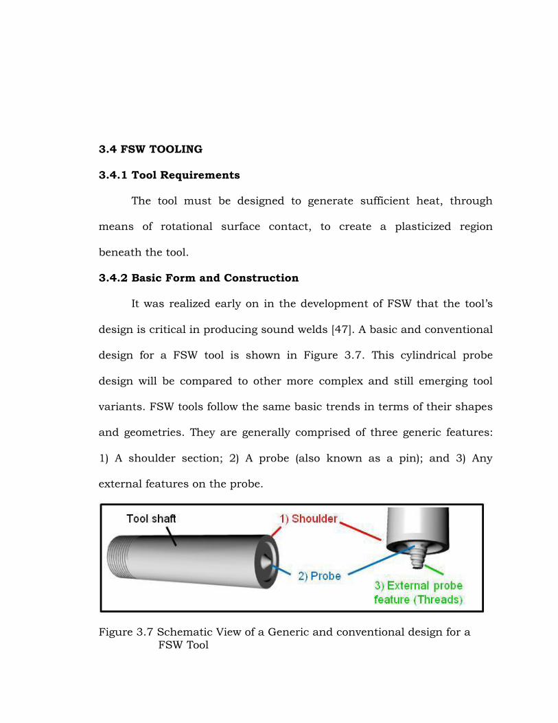
3.4.2 Basic Form and Construction
It was realized early on in the development of FSW that the tool‟s
design is critical in producing sound welds [47]. A basic and conventional
design for a FSW tool is shown in Figure 3.7. This cylindrical probe
design will be compared to other more complex and still emerging tool
variants. FSW tools follow the same basic trends in terms of their shapes
and geometries. They are generally comprised of three generic features:
1) A shoulder section; 2) A probe (also known as a pin); and 3) Any
external features on the probe.
Figure 3.7 Schematic View of a Generic and conventional design for a
FSW Tool
3.4.3 General Features
The three generic features have key roles to play during the
process, a failure in the design of one or more sections may lead to a
failure in the process. The initial design of the tool is tested and
optimized to find the ideal specifications for the geometry.
Tool Shoulder
The shoulder is designed as a relatively large, when compared to
the probe, profiled surface. Although the probe makes the initial contact
with the pre-welded material the shoulder has a larger contact area and
produces more friction.
Shoulder Diameter
A shoulder diameter which is too small could result in insufficient
heat being applied to the process through an inadequate contact area
between tool and material to be joined and therefore a failed weld or
broken tooling. To generate sufficient heat during the process the
shoulder diameter should be a minimum of 50% larger than the root
diameter of the probe with contact areas up to three times larger deemed
to be satisfactory [37]. The diameter of the tooling determines the width
of the plasticized region beneath the shoulder and the width of the
thermo-mechanically affected zone (TMAZ). The distinct semi-circular
trail indentation left in the wake of the tool is evidence of the deformation
caused by the shoulder rotation and its width is related to the shoulder
diameter [48].
Shoulder Profile
The amount of heat generated by the shoulder contact depends on
the profile of this surface. The shoulder profile can be designed to suit
the material being joined. This profile can increase or decrease the
contact surface area and so increase or decrease the amount of heat
supplied. This will also change the amount of deformation experienced by
the material at the top of the weld. This enables the tool to be specifically
designed for the materials or conditions in which it will be used. As the
shoulder profile rotates and makes contact with the material it traps
material within any contours of the profile and transports them with the
rotation of the tool. The material which has become caught in the
shoulder causes like-to-like frictional contact and superior weld closure
[47]. Figure 3.8 shows examples of possible shoulder profiles.
Figure 3.8 FSW Tool Shoulder Profiles Viewed from Beneath [33],
Including Scroll Profile [29]
One special shoulder profile called the scroll shoulder enables the
process to be carried out with the spindle set to a zero degree tilt angle.
This eliminates flashes of material extruded under the shoulder before
the weld is compressed but is far more difficult to set the tool‟s plunge
depth as there is no heel plunge.
The material is channeled towards the probe in the spiral shaped
groove. The ability to weld with no spindle tilt angle allows the
completion of non-linear welds, i.e. circumference welds [35]. An example
of a scroll profile is shown in Figure 3.8.
Frictional Heating and Deformation
The shoulder of the tool generates the majority of the heat required
for the process due to its larger contact area. The rotating surface of the
tool contacts the top surface of the material causing friction. The
softened material beneath the tool is said to be plasticized [44]. The
material does not melt, but is heated, to become softer and more
malleable. The plasticized region extends down through the weld directly
beneath the shoulder as it is translated through the material [47]. The
plasticized region of material undergoes heating from the friction and
also deformation from the rotation of the tool. As the tool shoulder heats
the material it is deformed and stirred by the tool‟s rotation. As the tool
is traversed through the weld material it compresses the joint, stopping
any plasticized material from being expelled from the top of the weld [47].
Tool Probe
Protruding from the shoulder profile is a cylindrical probe [37]
shown in Figure 3.7. This increases the contact area of the tool and
enables heat and deformation to penetrate to the weld root. The probe
makes the initial contact with the weld material before being plunged
through the material, for a typical butt weld the probe stops when the
tool shoulder contacts the material in the region of 0.1mm below the top
surface of the material. The probe rotates with the shoulder as it is
pulled through the weld material.
Probe Length
Figure 3.9 Probe Dimensions
The probe length dimension is shown in Figure 3.9. For a butt weld
the probe must be nearly as long as the material thickness [5]. For
example the shoulder penetrates the material by a small amount,
approximately 0.1mm, the probe must finish a small amount,
approximately 0.1mm, before the bottom surface of the weld material to
prevent total penetration of the tool. This means that roughly speaking
the tool‟s probe should be designed to be in the region of 0.2mm less
than the thickness of the material to be welded [36]. The probe length
must be designed for the desired weld depth. The probe must not contact
the backing plate as it would cause potential failures in the weld such as
root flaws caused by impurities included in the weld from the backing
plate, damage to the tool as a result of it being plunged into the backing
plate or an unsatisfactory weld root.
Root and Tip Diameter
The probe tip and root diameter dimensions are shown in Figure
3.9. A simple cylindrical probe would have an equal root and tip diameter
of approximately the same length of the probe [50, 51]. A more complex
conical shape would have a far larger root diameter than tip diameter
and would stand more chance of the probe breaking whilst under
process conditions. However a conical shape yields superior welds than a
cylindrical probe [52]. Friction stir welding probes are commonly
designed as frustums [49].
Probe Profile
The angle the side of a probe makes with the vertical centre line of
the tool is the probe angle as shown in Figure 3.10 [52].
Figure 3.10 Probe Angle Schematic
The parallel sided cylindrical probe shown on the left hand tool of
Figure 3.10 has a probe angle of zero. This is a more prominent
protrusion from the shoulder and would be harder to plunge into and
traverse through the material to be joined than the tool on the right.
The larger probe angle shown on the right allows a suitable radius
to be used at its base providing a more gradual transition between the
shoulder profile and the probe. This design allows easier plunging and
traversing. As this angle increases, the amount of heat generated
increases. A tapered cylinder or conical probe produces vertical material
flow as well as the rotational flow caused by the tool‟s rotation [52]. The
probe, much like the shoulder, exhibits a profile when viewed from the
side or underneath. A probe‟s profile can be circular, nominally oval,
flattened, or re-entrant. Some probe profiles are shown in Figure 3.11.
Figure 3.11 Examples of Possible Probe Profiles [49].
Frictional Heating and Deformation
The main source of heat for the process comes from the shoulder
contact, however for thicker welds (typically of 1.2mm depth and above)
the shoulder does not have enough influence on the weld root. It is the
probe which generates the heat in the weld root [47]. The probe ensures
sufficient deformation and heating of the material throughout the depth
of the weld.
The probe causes surface contact and therefore frictional heat
through the thickness of the material it also causes deformation in the
form of a material movement around the probe with the motion of the
tool rotation. As explained in Chapter 2, the FSW process is like an
extrusion process, the material flows around the probe and consolidates
behind the tool. Coinciding with this rotational material movement a
vertical movement can occur due to probe shape and or re-entrant
features.
Threaded Probes
Some probes contain more complex geometry in the form of a
helical ridge [49] or external thread. This external thread acts in the
same way as any shoulder profile, changing the surface contact and
deformation experienced by the weld material. These threads are
designed in a specific way. As the tool is rotated the helix would either
encourage or resist the plunge into the material depending on the pitch.
The pitch of a screw accepts the material when rotated clockwise. This
has a right-hand-pitched thread. The thread on an FSW probe is
designed to oppose the plunge and push material downwards instead of
drawing it upwards. This requires a left-hand-pitched thread (LH thread),
when the spindle rotates in a clockwise direction. The helical ridge
pushes the weld material towards the bottom or weld root. This force
produces vertical mixing to accompany the rotational mixing. The thread
size or pitch will determine how successful the mixing of the weld
material is.
A small pitch may not produce enough deformation and so
bonding of the stirred material is impaired. However too large a pitch will
cause the tool to act like a drill and expel weld material before the
shoulder makes contact to compresses the material [51]. The probe
works as an auger, immersed in the plasticized weld material [47].
Re-entrant Features
More recent tools have moved away from smooth and threaded
cylindrical probes and exhibit complex features. These re-entrant
features affect the tool‟s ability to be traversed through the material
whilst increasing the tool‟s influence on the material. Re-entrant features
reduce the actual (static) volume of the probe whilst leaving the
rotational (dynamic) volume the same. A typical ratio of dynamic volume
to static volume for conventional probes would be 1.1 :1, this volume is
significantly different to that of the MX Triflute™ which is 2.6:1. This
difference in ratio aids the material flow. The preferred number of
features is an odd number of equally spaced features, this maintains
maximum bending strength [47]. The MX TrifluteTM, shown in Figure
3.12, has three equally spaced flutes, a frustum probe and a profiled
shoulder. This represents a modern FSW tool showing re-entrant
features.
Figure 3.12 MX Triflute™ FSW tool [47].
3.4.4 Tooling Variations
Due the amount of interest in the subject of FSW there have been
many advancements in the area of FSW tooling. This research has
enabled the process to be carried out faster, with longer and more
reliable welds produced. As a result of this there are many variations on
the basic FSW tool design from single piece basic shapes to composite
tools. These will be outlined here with information regarding other tooling
designs included in Appendix F.
Single Piece Tools
The simplest of tools are those made completely out of one piece of
material, usually steel. These tools are hard to make because the probe
and shoulder have complex geometries and must be machined out of the
same piece of material. The probe shape is usually a flat ended, smooth,
cylinder as shown in the top left corner of Figure 3.13. This extends to
threaded cylinders and fluted cylinders. A truncated cone or frustum is a
more commonly used design. Like the cylindrical probe this can be
smooth, threaded, fluted or a combination.
Figure 3.13 Possible Probe Designs [12].
Composite Tooling
A simple but effective improvement to the basic conical probe
design allows for more specific process optimization for the application
involved. As the name suggests the tool is not made from a single piece of
material. The probe and shoulder are made from different materials. This
allows the probe to be made from a substantially harder, more durable
material while the shoulder is made from cheaper less wear resistant
material. The difference in materials gives rise to further optimization.
For example the probe for a thick section weld tool can be made from a
high temperature, physically resistive material such as Polycrystalline
Cubic Boron Nitride (PCBN). This is an abrasive but expensive material
so making the entire tool from PCBN is not cost effective. The probe can
be made from this physical and chemically resistant material but the
shoulder only needs a surface coating, this allows the majority of the tool
to be crafted from a less expensive but still temperature resistant
material such as high carbon content steel [35].
3.4.5 Weld Variables
The weld variables are the factors which must be taken into
account when designing and building FSW tools. These are different to
the process variables such as spindle speed and feed speed.
Weld Material Type
The most commonly FS Welded material is aluminium and its
alloys. This material is deemed difficult to join using conventional fusion
welding techniques due to its susceptibility to porosity and flaws due to
inclusions. A wide selection of materials can be potentially joined using
this process, a definitive list would be metals, alloys, composites and
some thermoplastics [37].
Metals and Alloys
The FSW is a solid state joining process and so accommodates a
wide range of possible applications for joining metals. So far research has
been made into the continuous welding of aluminium, lead, copper,
magnesium, steel and titanium [39, 47]. This represents a cross-section
of the metals which could be used. Aluminium is regarded as an easy
material to join using this technique when previously some of its alloy
compositions had been deemed virtually impossible to join using
conventional fusion welding methods [36].
Dissimilar Materials
The process can also join dissimilar materials. A joint of
aluminium 6xxx to aluminium 2xxx would cause problems during fusion
welding when the molten weld pool cools. The FSW process is a solid
state process and has been proven to be a reliable welding technique to
join dissimilar metals, for example, the joining of aluminium to mild steel
[49].
Thermoplastics
It is typically metals which are friction stir welded, plastics could
be joined but the process is heavy handed and many simpler means of
plastic bonding are commercially available [37].
Tool Material
The tool must be made from a material which can withstand the
process and offer enough frictional heat generation. When selecting a
material from which to manufacture the FSW tool, the material to be
welded must be considered. The tool material must be sufficiently
stronger and more wear resistant than the material to be welded. A tool
made from a material which is too soft will wear down to an unusable
state very quickly due to the constant abrasive contact involved in the
process. Tools currently used for industrial applications are capable of
completing over 1000m of FSW without the need to change tool [49].
Aluminium can be joined using a tool made from silver steel [53],
however if the weld material was to be steel, the tool would have to be
more temperature resistant, for example tungsten with a ceramic
coating. This means the selection of an FSW tool material must be based
on the weld material properties.
Another type of tool material under investigation is ceramic tools. A
ceramic tool is more resistant to abrasion and so will not wear as much.
This tool would also be able to generate the temperatures required to join
steels. Ceramic although tough is a more brittle substance than metal
and so the traversing of the tool would be its biggest challenge.
Weld Depth
The depth of the weld will decide the overall geometry of the tool,
more critically the probe length. Research in to the friction stir welding
process has commonly been in the range of 1.2mm to 6mm thick plates
in a butt or lap weld configuration. Thinner than 1.2 mm is considered to
be thin section and thicker than 6mm is considered to be thick section
[44]. Thin section FSW in the order of 0.4mm has been reported to have
been carried out by Airbus [54], whilst thick section materials in the
order of 50 to 75mm thick section have been successfully joined at TWI
in Cambridge [55] representing the extremes of the scale. The range of
material thicknesses welded is consistently within 1mm (thin gauge) and
50 to 75mm (thick gauge). The interest for the joining of material less
than 1mm thick lies in the aeronautical area, joining air craft frames and
body panels. With FSW making ground in the attempts to reduce weight
on aero planes replacing riveted lap joints with thin gauge FSW butt
joints. Sound lap welds have been created in 0.3mm thick aluminium
giving rise to the title Micro Friction Stir Welding (μFSW) [56].
3.4.6 Summary
The friction stir welding tools used coupled with the process
parameters used ultimately govern the final microstructure produced by
the welding process. Through the evolution of the FSW process tool
designs have become more complex and optimized to produce quality
welds in most materials. It has been shown that features on the tool
probe are vital in creating friction stir welds which are fully bonded in
the weld root. Threads, flats and flutes have been utilized to increase the
deformation and heat generated by the tool, ensuring a suitably bonded
weld root. All the tools used for this thesis are for use with conventional
rotary friction stir welding, some more recent variants of FSW and their
advanced tooling designs will be covered in Appendix F.
3.5 APPLICATIONS OF FRICTION STIR WELDING
3.5.1 Applications of Friction Stir Welding in Different Geometries
The FSW process can also cope with circumferential, annular, non-
linear, and three dimensional welds. Since gravity has no influence on
the solid-phase welding process, it can be used in all positions:
• Horizontal
• Vertical
• Overhead
• Orbital.
The process has been used for the manufacture of butt welds,
overlap welds, T-sections, fillet, and corner welds as shown in Figure
3.14. For each of these joint geometries specific tool designs are required
which are being further developed and optimized [57]
Figure 3.14 Schematic illustrations of the T-sections [58]
3.5.2 Applications of Friction Stir Welding in Aluminum Alloys and
other Materials
FSW can be used for joining many types of materials and material
combinations. Continuing development of the FSW tool, its design and
materials have allowed preliminary welds to be successfully produced in: