23
The Details of Modern Architecture N.G. Carrillos
| Date post: | 09-Mar-2016 |
| Category: |
Documents |
| Upload: | gcarrillos |
| View: | 223 times |
| Download: | 6 times |

The Details of Modern ArchitectureN.G. Carrillos

Carlos Zapata and the Reinventionof Modernism
Zapata’s work presents a continuous alternating of oppositions that end up mutually eluding each other: peacefulness answers
excessiveness, heaviness answers lightness, straightness-obliqueness, openness-closure, serenity-restlessness, stillness-movement,
freedom-necessity. This is why this piece of architecture turns out to be controlled, on the whole. Stridency is only apparent. What is
real is the quiet, sensuos taste for shapes and materials.
Aldo Castellano, The Restlessness of Architecture
The Venezuelan architect Carlos Zapata is trying to turn another page in
the book of Modernism. He is trying to redefine what is ‘modern’ today
by shedding away associations with the shortcomings of the movement.
After graduating from Columbia in the mid-80’s, Zapata was fortunate
enough to find work at the progressive offices of Ellerbe Beckett in New
York City. It was here, while working under the tutorship of Peter Pran,
that he was able to formulate a way to pursue a modernist aesthetic that
does not come at the expense of a building’s performance.
Above all things, Modernism lost favor because its high ambitions for a
universality of means and processes ultimately disregarded the specifics of
people and place. The proponents of mass production and standardization,
while noble in their cause, stalled the evolution of architecture through the
adoption of objective tenets such as generalization, repetition and regular-
ity. By extension, this de-emphasis on project specifics led to the creation
of many poorly detailed modernist buildings, fundamentally insensitive to
the needs of their inhabitants and the demands of the environment. The
architecture of Carlos Zapata, in the other hand, aims to reinvent Modern-
ism through a reversal of these priorities. In his work, it is not universals
but circumstantial particulars such as context, process, and people that
determine and ultimately enrichen the outcome of the project.

1.1
1.31.2

3 Carlos Zapata and the Reinvention of Modernism
1.1 Model. Competiton entry for Canadian National
Royal Trust Office Building Complex,
Toronto, Canada, Ellerbe Becket,1989.
1.2 Model. Competition entry for Canadian National
Labbats Headquarters, Toronto, Canada,
Ellerbe Becket, 1990.
1.3 Model. Competition entry for Consolidated Terminal
for American Airlines / Northwest Airlines,
John F. Kennedy International Airport, New York,
Ellerbe Becket, 1988.
1.4
1.51.6
Chicago Bears Stadium & Midway
Wood + Zapata
Chicagoland, Indiana, 1996
1.4 Model.
1.5 Plan and section of the stadium.
The Bridge - Cinema De Lux
University of Pennsylvania Parking Garage
Wood + Zapata
Philadelphia, Pennsylvania, 2000
1.6 View.

1.7
1.8

Carlos Zapata’s design process is similar to that of an artist. He, is
interested in ideas of motion, balance, hierarchy, and proportion. More
specifically, he likes to consider the different ‘weights’ of surfaces in a
manner not unlike artists assess equilibrium in their compositions. Given
this predilection, it’s not surprising to discover that Zapata’s design pro-
cess is also very sculptural. He prefers foam models over digital ones.
His studio is filled with models which are constantly in the process of
development. In effect, it’s this preference for designing in-the-round that
lends his buildings their sculptural quality. However, Zapata is quick to
point out that form is only a means to a greater end:
“Form as an end unto itself leads to formalism. This is because this
tendency doesn’t go inwards, but outwards. Only a live interior can own
a live exterior. Only vital intensity is in possession of formal intensity. Ev-
ery how is supported by a what. That which is shapeless isn’t worse that
which is excessively shaped. The former is nothing, the latter is just show-
ing off. Real form implies real life. But not past or only imagined form.
This is the criterion: we don’t evaluate the result, but the beggining of the
process of creating forms and shapes. It is precisely this process which
reveals wether it was born in itself. This is the reason why the process of
the attribution of a form or shape is so important to me. For us life is the
decisive factor, in all its fullness, in its spiritual and real bounds.” 1
Similar to Mies, Zapata is also very interested in the expressive quality of
materials. Particularly, the way in which these respond when prompted
by the introduction of light. As a result, his surface pallete tends to favor
highly receptive(and complimentary) materials such as aluminum, glass,
and stone. Structurally, he prefers steel and concrete over masonry. This
last one completely absent in his body of work.
After establishing his own studio in 1991 he continued to develop and
mature this unique focus upon the specifics of the project . This approah
is evident in both, his built and in his un-built projects. The U-Penn
mixed-use project (1.6), for instance, is a good example of a project that
was enriched by its programatic complexity. Here, his employment of a
perforated metal envelope not only provides good overall shading but also
unifies the multiple funtions within the program.
5 Carlos Zapata and the Reinvention of Modernism
New Stadium at Soldier Field
Wood + Zapata
Chicago, Illinois, 2003
1.7 Aereal View.
1.8 North entrance facade.

A
B
C
D
E F
G
H
I
1.16
1.17
1.18 1.19

STRUCTURE
Zapata does not allow structure to determine the outcome of the design.
His emphasis on the contextual specifics keeps him focused upon the es-
sence of the project. However, he is not afraid to delve into unpresedented
territory; he turns to unconventional solutions if that is what the project
requires. Accordingly, his structures often tend to be unconventional.
This unconventionality, however, is not to be confused with irrationality.
The structure at Soldier Field is a good example of this. Here, in order to
achieve levitating effect of the new ‘bowl,’ a steel frame system was re-
quired. The system is actually very straightforward construction. As 1.11
illustrates, the structural framing is composed massive built-up steel gird-
ers ( the width of which determines the transversal span of the new bowl)
that take up the load of the bench seating area and distributes it down
to the columns below through plate connections. To prevent the lateral
movement of these girders, secondary steel framing (in the form of open
web steel trusses and steel I beams) and steel bracings are provided. The
angled wide flange columns, which are doing the most work in the system,
are further reinforced through the use of steel pipe braces. The steel tubu-
lar catwalks, which I will expand upon later, are here to provide access for
the maintenance of the field light strip band that hovers above the bench
seating section. These are connected to the steel girders through a welded
plate connection. In addition, steel skin wind girts are introduce to provide
a support for the stainless steel interlocking planks that clad the exterior
of the bowl. Lastly, pre-cast steel ‘seats’ were included to provide a joint
connection from which to attach onto the fan’s seats. The images 1.12 and
1.14 show the way this system looked as assembly was being carried out.
Image 1.12 shows the ‘cracks’ introduced in the latter stages of the design
phase. As previously outlined, these were introduced to maximize the
views of the urban scale at large, thereby making a contextual connection
with the city.
11 Carlos Zapata and the Reinvention of Modernism
New Stadium at Soldier Field
Wood + Zapata
Chicago, Illinois, 2003
1.16 Framing.
A Steel tubular catwalk supports.
B Built-up steel girder.
C Secondary steel framing.
D Secondary open-web truss framing.
E Skin wind girts.
F Precast seating steel “seat.”
G Steel bracing.
H Steel pipe brace.
I Steel pipe-enclosed wide flange columns.
1.17 Under construction.
Steel frame.
1.18 Under construction.
North scoreboard.
1.19 Under construction.
Bench seating.

1.20
1.21
1.22
1.23
KLEIN RESIDENCE
Just like Asplund, Aalto and Neutra before him, Zapata is obsessed with
light. In contrast to these, however, his fascination does not originate
from an architectural background, but from a cultural one. In the follow-
ing passage, the architect expands upon design his life-long fascination
with light:
If we stop at pure geometry, we create a house that doesn’t take the out-
side into consideration, nor natural light or the very site of the house. I
pull volumes away from each other to create spaces that allow light in
which can control moods and create a sort of excitement: light moving
along a wall is pleasant to behold. When certain spaces are opened and
slanted, light can pass through and space starts moving. In the living room
I created an aura of light similar to that which hangs over the heads of
saints in South American religious paintings by making light filter through
the sides of the suspended ceiling. When these possibilities have been
explored, it is hard to go back to boxes.” 3
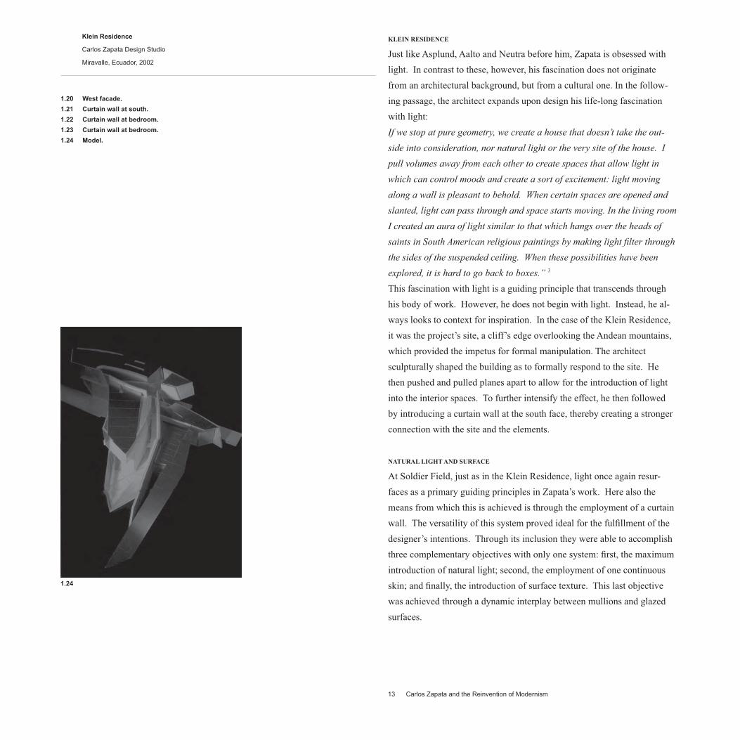
This fascination with light is a guiding principle that transcends through
his body of work. However, he does not begin with light. Instead, he al-
ways looks to context for inspiration. In the case of the Klein Residence,
it was the project’s site, a cliff’s edge overlooking the Andean mountains,
which provided the impetus for formal manipulation. The architect
sculpturally shaped the building as to formally respond to the site. He
then pushed and pulled planes apart to allow for the introduction of light
into the interior spaces. To further intensify the effect, he then followed
by introducing a curtain wall at the south face, thereby creating a stronger
connection with the site and the elements.
NATURAL LIGHT AND SURFACE
At Soldier Field, just as in the Klein Residence, light once again resur-
faces as a primary guiding principles in Zapata’s work. Here also the
means from which this is achieved is through the employment of a curtain
wall. The versatility of this system proved ideal for the fulfillment of the
designer’s intentions. Through its inclusion they were able to accomplish
three complementary objectives with only one system: first, the maximum
introduction of natural light; second, the employment of one continuous
skin; and finally, the introduction of surface texture. This last objective
was achieved through a dynamic interplay between mullions and glazed
surfaces.
13 Carlos Zapata and the Reinvention of Modernism
Klein Residence
Carlos Zapata Design Studio
Miravalle, Ecuador, 2002
1.20 West facade.
1.21 Curtain wall at south.
1.22 Curtain wall at bedroom.
1.23 Curtain wall at bedroom.
1.24 Model.
1.24

A
B
C
D
E
F
G
H
I
J
K
New Stadium at Soldier Field
Wood + Zapata
Chicago, Illinois, 2003
1.25 Primary and secondary structure at curtain wall.
A Steel column.
B Primary girder.
C Cross girder.
D Edge beam.
E Vertical aluminum mullion. The mullion is continuous throughout.
F Horizontal aluminum mullion.
G Steel shelf angle. Continuous structural support.
H Galvanized steel angle support. The angles support the
mullions from the edge of the slab.
I Vertical structural steel support.
J Vertical sag rod.
K Horizontal structural tubing.
1.26 Curtain wall at Promenade.
1.25

PRIMARY AND SECONDARY STRUCTURE
The structural clarity at Soldier Field is pervasive throughout. At the
building’s perimeter, the clear dictinction between primary and secondary
structure is yet another example of this principle. At each level, primary
girders run transversally, supported by columns that span continuously
from foundation to ceiling. Cross girders and edge beams pick up the
live and dead loads in their respective levels and transfer them on to the
columns. These beams are fastened onto the primary girders through
the use of bolted steel plates and angles. The entire curtain wall system
is bolted onto galvanized steel angles imbeded into the slab’s edge. The
system is additionally supported at ground level through the employment
of vertical steel rods anchored upon a horizontal steel tube that runs paral-
lel to the wall. This rectangular tube, in turn, is connected to the primary
structure through another tubular steel member. The vertical mullions of
the system run “continuously” throughout the entire height of the wall. At
the louver section, however, they are substantiated by a vertical structural
steel support. From top to bottom, the sequence goes as follows: the
upper vertical mullions sit upon shelf angles, the shelf angles are attached
onto vertical supports,which, in turn span behind the louvers and the sha-
dox box before finally reconnecting back to vertical mullions at the lower
end. The attention given to these structural connections is very throrough.
This, however, is not surprising given Zapata’s adherence to sound detail-
ing principles.
THERMAL MOVEMENT
Another characteristic of the curtain wall that deserves further consider-
ation is the precautions taken to prevent thermal movement. The curtain
wall at Soldier Field addresses this issue in two ways: through the use of
interlocking split aluminum mullions and the introduction of expansion
joints. As employed in some of the masterpieces of High Tech architec-
ture, such as the Lloyd’s of London (Richard Rogers), the Hong Kong and
Shanghai Bank (Norman Foster), and the Institut du Monde Arabe (Jean
Nouvel), the split mullion is a means to prevent the movement created
by the expansion and contraction that materials undergo as changes in
temperature occur. As noted in Jean Nouvel’s Institute du Monde Arab,
another good reason to use this type of mullions is the added flexibility
they provide in the assembly process.4 At Soldier Field, where the curtain
wall curves continuously, this type of system was not only advantageous
but essential. The reason for this is because the assembly of the curtain
wall required the employment of a mullions system that could
15 Carlos Zapata and the Reinvention of Modernism
1.26

A
B
C
D E F
G H
I
J
K
L M
N
O
P
Q
R
S
1.27 1.28
Q
A
B
C
D
E
F
G
H
I
J
K
L
M
N
O P
S
T
U
R
T
U

17 Carlos Zapata and the Reinvention of Modernism
New Stadium at Soldier Field
Wood + Zapata
Chicago, Illinois, 2003
1.27 Roof section.
A Primary girder.
B Galvanized steel angle support.
C Edge beam.
D 1/2” dense glass substrate.
E 3” metal roof deck.
F Vapor barrier.
G 3” rigid insulation.
H Single ply TPO membrane.
I 5/8” cement board with metal stud support.
J Setting wood block.
K 1/8” thick aluminum coping, PVDF coated.
L Galvanized sheet metal closure.
M Cant strip.
N GL-5: 1/4” thick shadow box glass.
O Snap-on aluminum cap, PVDF coated.
P 3” thick semi-rigid insulation with galvanized
sheet metal back pan.
Q Painted sheet metal shadow box. This system
is used to add depth to the wall.
R GL-4: 1” thick insulated vision glass with frits.
S Aluminum trim, finish to match enclosure system.
T Hung gypsum panel ceiling.
U Spring isolation hangers.
1.28 Wall section.
A Primary girder.
B Edge beam.
C 6” concrete slab on 3” metal deck.
D 4” vinyl base.
E Cant strip.
F 5/8” gypsum board with metal stud support.
G Aluminum sill finish with back support,
H Vertical aluminum mullion, PVDF coated.
I GL-4: 1” thick insulated vision glass with frits.
J Snap-on aluminum cap, PVDF coated.
K Steel shelf angle. Continuous structural support.
L Vertical structural steel support.
M 3” thick semi-rigid insulation with galvanized
sheet metal back pan.
N Aluminum panel, PVDF coated.
O Galvanized steel angle support.
P Steel bracket attached to edge of slab.
Q Custom extruded aluminum louvers with insulated
sheet metal blank off between ducts, PVDF coated.
R GL-3: 1 1/4” thick laminated-insulated glass with frit.
S Aluminum trim, finish to match enclosure system.
T Vertical sag rod.
U Wood ceiling planks supported by 16” stud framing.
be adjusted, or tilted, to account for the curvature of the wall. In addition
to this system, Zapata also employs expansion joints at intermittent inter-
vals with the mullions. Expansion joints act to prevent thermal movement
in the same manner that split mullions do. At Soldier Field, given the
mass quantities of concrete employed, this type of system was essential to
the safety and overall success of the project.
INSULATION
The inappropriate insulation of surfaces in one of the harshest criticisms
lashed against the modernist. Some, like Frank Lloyd Wright, ardently
believed that it was not necessary to insulate walls or floors at all. Ac-
cording to Wright, only roofs and the building’s edge (at grade) required
insulation.5 Rudolph Schindler, having worked for some time at Wright’s
office, carried on with these mystical practices.6 A crowd favorite
amongst architects, Le Corbusier, also contributed his part to the damage.
According to Ford, the Swiss-born architect had no concern, or perhaps no
interest, for the implications of environmental impact upon architecture.7
Last, but not least, we could not talk about bad detailers without mention-
ing Eero Saarinen. This ‘talented’ architect further cemented the public’s
distaste for modernism by making an enfilade of poorly insulated steel
buildings throughout America.8 Carlos Zapata breaks away from these ex-
amples by providing for the proper insulation of surfaces in line with the
conventions of current practice. In particular, the insulated glass system
employed at Soldier Field deserves further consideration. Zapata uses
three types of glass for the curtain wall. In accordance with his emphasis
on design specifics, each of these serves a specific purpose. The roof sec-
tion on 1.27 illustrates how two of these are applied. GL-5 is a single pane
glass of 1/4” thickness. Its application is similar to that of spandrel glass
on conventional office buildings. The only difference here is that it also
acts, in conjunction with the recessed aluminum shadow box behind it, as
a means to activate the wall by giving it an added sense of depth. Below
the shadow box glass is the GL-4. This is a 1” thick insulated vision glass
with ceramic frits. This type of glass is very convenient to use in applica-
tions where the reduction of sun glare is of particular importance. Last
but not least is the GL-3. This is a 1 1/4”
thick laminated-insulated glass with ceramic frits used particularly for cur-
tain wall applications. The only difference between the GL-3 and the GL-
4is that the GL-3 comes with a thicker glass pane that has been laminated
in order to protect against impacts and to account for the added angle of
incidence the sun creates at ground level.

1.29
1.30
A B
C D
E
F
G
H
I
J
K
L
M N
A B
C
D
E
F
G
H
I
J
K
L

1.29 Alternate roof section.
A 1/2” dense glass substrate.
B 3” rigid insulation.
C Single ply TPO membrane.
D 5/8” cement board with metal stud support.
E 1/8” thick aluminum coping, PVDF coated.
F Setting wood block.
G Insulated aluminum panel system, PVDF coated.
H Galvanized sheet metal closure.
I 3” metal roof deck.
J Galvanized steel angle support.
K 4” X 4” galvanized steel tube.
L Panel clip and fastener.
M Primary girder.
N Edge beam.
1.30 Alternate wall section.
A 6” concrete slab on 3” metal deck.
B 4” vinyl base.
C Cant strip.
D 5/8” gypsum board with metal stud support.
E Aluminum sill finish with back upport, PVDF coated.
F GL-4: 1” thick insulated vision glass with frits.
G Snap-on aluminum cap, PVDF coated.
H Galvanized steel angle support.
I Steel bracket attached to edge of slab.
J Insulated aluminum panel system, PVDF coated.
K Primary girder.
L Edge beam.
ALTERNATE WALL SYSTEM
The alternate details I propose are a modification of Zapata’s details at
the Soldier Field curtain wall. In my analysis of his details, three themes
stand out with consistency: light, form and materials. Light is the source
of inspiration, form is the means to introduce light, and materials cor-
respond through performance and expression. In the alternate sections
(1.29 and 1.30), I substituted Zapata’s glazed curtain wall system with a
perforated aluminum panel system (also known as a rain screen). Light is
addressed by replacing the stadium’s floor-to-ceiling glazed wall with an
insulated/fritted window encased in an aluminum frame. The triangular
mullion caps in Zapata’s wall system have been substituted with flat alu-
minum caps. In Zapata’s wall, these caps contributed by giving volume
and adding texture to an otherwise homogenic surface. In this version,
however, since the aluminum panels are already providing the needed
texture, the inclusion of triangular protrusions is of little assistance. Form
remains loyal to Zapata’s version. Zapata’s diagonals are not unsound.
They are formal responses to contextual and programmatic needs. In
here, as in Soldier Field, the intent behind the diagonal tilt of the wall is
to maximize the amount of light that enters the interior spaces. Finally, I
believe that the introduction of a textured, pressure-differentiating, anti-
corrosive system such as the aluminum rain screen would be very much
in keeping with Zapata’s criteria for material selection.
FIRE PROTECTION AND MATERIAL DETERIORATION
At Soldier Field the argument of whether to use a monolithic or a layered
system of construction did not exist. Due to the fire hazard it represents,
building codes in the United States do not allow the use of exposed steel
in buildings that are taller than three stories.9 During the 50’ and 60’s,
both, Mies and Saarinen built a large number of monolithic exposed steel
buildings in America. These buildings, in addition to posing a fire threat,
required a lot of maintenance and performed very poorly in aspects of
thermal efficiency.10 Zapata, by contrast, confronts these issues head on
at Soldier Field. To prevent fire hazards, all structural steel has been
insulated: spray-on foam insulation has been used for the beams and steel
deck and gypsum boards have been used for the columns. This practice
also eliminates the thermal bridges that are created when steel is left ex-
posed. As an additional precaution, safing, a fire and smoke retardant, has
been inserted into the gaps between slab and curtain wall. Aluminum is
one of Zapata’s favorite materials to use. As we can see from the sections
on 1.27 and 1.28, he employs it heavily throughout the entire
19 Carlos Zapata and the Reinvention of Modernism

A
B
C
D
E
F
G
1.31
1.32
1.33
1.34
A
B
C
E
F
G
H
I
J K
L
A
B
C
D
E
F
H
G
I
J
K
G

New Stadium at Soldier Field
Wood + Zapata
Chicago, Illinois, 2003
1.31 Section at Promenade/Concourse level.
A Vertical sag rod.
B Vertical aluminum mullion, PVDF coated.
C GL-3: 1 1/4” thick laminated-insulated glass with frit.
D Horizontal aluminum mullion, PVDF coated.
E Snap-on aluminum cap, PVDF coated.
F Fin tube radiation, coated to match curtain wall.
G Expansion joint.
H Aluminum sill starter coping, PVDF coated, continuous at
curb.
I New concrete slab with 5” higher ADA detection curb.
J Secondary steel concourse framing.
K Primary girder.
L Steel column.
1.32 Section at Promenade/Concourse level.
A New concrete slab with 5” higher ADA detection curb.
B Snap-on aluminum cap, PVDF coated.
C GL-3: 1 1/4” thick laminated-insulated glass with frit.
D Aluminum sill starter coping, PVDF coated, continuous at
curb.
E Expansion joint.
H Fin tube radiation, coated to match curtain wall.
G Primary girder.
H Secondary steel concourse framing.
I Cross beam.
J Steel column.
K Slide connection for expansion joint.
1.33 Interior at Concourse level.
1.34 Detail of curtain wall structural support.
A Steel column.
B Vertical sag rod.
C Galvanized steel angle support.
D Snap-on aluminum cap, PVDF coated.
curtain wall; the mullions and their caps, the ‘shadow box’ panels,
the trim, the sill, the parapet’s coping, the expansion joint coping, and
even the diffuser are all made of aluminum. It is important to note that
all of these examples have been PVDF coated to prevent their corro-
sion. The advantages that aluminum has over exposed steel are many.
It can be extruded in a variety of shapes, it can be easily insulated, it
can be painted to match any finish and it can, as formerly mentioned,
also be left exposed to the elements.11 With all these considerations in
mind, it is easy to see why Zapata likes it so much.
VENTILATION
In a building the size of Soldier Field, issues of ventilation are of
great concern. It is imperative that this type of buildings is allowed
to ‘breathe’ and distribute air properly in order to prevent condensa-
tion and moisture buildup in its surfaces. At the curtain wall, Zapata
addresses these concerns in two ways: through the use of louvers
and diffusers. The introduction of natural ventilation through the
employment of aluminum louvers allows the building to minimize the
moisture content and the mildew build up that can occur when sur-
faces are not provided with a means from which to ‘breathe’ property.
The choice of aluminum, as previously outlined, is a very sound one
when you take into consideration the fact that these components will
have constant exposure to the elements. In 1.28 we can witness the
manner in which this system is supported through the employment of
a vertical structural member. At the base of the curtain wall, Zapata
prevents the buildup of condensation and heat loss through the use
of a fin tube radiator. This type of ventilation system is a form of
radiant heater/cooler that essentially operates by forcing the flow of
hot/cold water through a copper pipe and allowing it to radiate over
to the desired spaces/surfaces. Frank Lloyd Wright pioneered its use
very early on and influenced others such as Richard Neutra to follow
in the same footsteps.12 More recently, the High Tech architects have
adopted similar systems for inclusion in their curtain wall applications. 13 Among some of the seminal buildings of the twentieth century
that include some variation of this systems are Frank Lloyd Wright’s
Imperial Hotel 1922, Eero Saarinen’s TWA Terminal at JFK, Richard
Roger’s Lloyd’s of London and Norman Foster’s Hong Kong and
Shanghai building.
21 Carlos Zapata and the Reinvention of Modernism

A
B
C
D
E
F
H
1.35
G
MATERIAL SELECTION
Throughout the 20th century, architects and artists have been preoccupied
with the search for the appropriate means to express motion. The Futur-
ist and the Russian Constructivist were not so much concerned with the
mechanics of the objects they studied as much as they fascinated with
their surface appearance.14 Similarly, Le Corbusier, in his study of the
machinery of the new age, only did so at surface value. Perhaps it was
not until Eero Saarinen’s office conducted its research of industrial objects
that the real value of these objects came to be applied in architecture. In
spite of his shortcomings elsewhere as an architect, it is in this area where
Saarinen redeems himself as a true innovator. Saarinen’s adaptation of
industrial components such as gaskets and Cor-ten, taken from the auto-
mobile and rail industries respectively, set a precedent for future material
exploration.15 The British architect Norman Foster followed suit by con-
ducting substantial research into the aircraft industry. From these studies,
principles such as the ‘tolerance’ of materials (and craftsmanship) have
been adapted into the design of his buildings. However, Foster does not
deny that his appeal for aerodynamic design is both, intellectual and aes-
thetic. Neither does designer Carlos Zapata. As an architect fascinated
with motion in architecture, he has also sought to find the appropriate
means of expression. Just like Foster, he looks to find materials that can
marry aesthetics and functionality. A good case sample can be found in
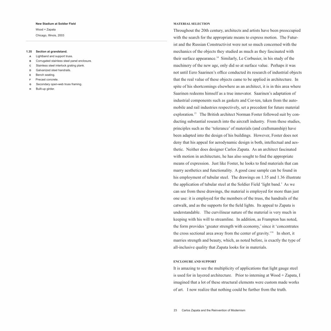
his employment of tubular steel. The drawings on 1.35 and 1.36 illustrate
the application of tubular steel at the Soldier Field ‘light band.’ As we
can see from these drawings, the material is employed for more than just
one use: it is employed for the members of the truss, the handrails of the
catwalk, and as the supports for the field lights. Its appeal to Zapata is
understandable. The curvilinear nature of the material is very much in
keeping with his will to streamline. In addition, as Frampton has noted,
the form provides ‘greater strength with economy,’ since it ‘concentrates
the cross sectional area away from the center of gravity.’16 In short, it
marries strength and beauty, which, as noted before, is exactly the type of
all-inclusive quality that Zapata looks for in materials.
ENCLOSURE AND SUPPORT
It is amazing to see the multiplicity of applications that light gauge steel
is used for in layered architecture. Prior to interning at Wood + Zapata, I
imagined that a lot of these structural elements were custom made works
of art. I now realize that nothing could be further from the truth.
23 Carlos Zapata and the Reinvention of Modernism
New Stadium at Soldier Field
Wood + Zapata
Chicago, Illinois, 2003
1.35 Section at grandstand.
A Lightband and support truss.
B Corrugated stainless steel panel enclosure.
C Stainless steel interlock grating plank.
D Galvanized steel handrails.
E Bench seating.
F Precast concrete.
G Secondary open-web truss framing.
H Built-up girder.

1.36
1.37
A
B
C
E
F
A
B
C
D
E
F
D

In actuality, in steel construction, just about anything that needs to be
braced or supported is done with nothing more than steel studs, plates,
and angles. At Soldier Field we see light gauge employed just about
anywhere: at the knee wall, supporting the mullions, bracing the ceilings,
and even used to make the formwork of sculptural elements such as the
curved rim at the top of the cantilevered bleachers. In the section on 1.37
we can truthfully attest for the versatility of light gauge steel. Essen-
tially, the rim’s formwork is composed entirely of light gauge construc-
tion. Initially, studs extend from the uppermost trusses (whose job at this
point is to brace the steel tubular arms) and connect unto a curved light
gauge member that has been extruded to take the shape of the rim. Steel
channels, in turn brace these curved members and, in conjunction, all of
these provide the necessary support for the corrugated steel envelope to
anchor on to. On the bleacher side, the same method it is employed once
again. The only difference on this side is that only straight members are
applied to create the sidding’s support. Here again, as in the curtain wall,
we see how Zapata employs different materials at the point where forms
shift on to another direction. In the same manner that aluminum channels
provide a transition for the glass at the curtain walls, corrugated steel is
hereby employed to provide the transition from the grating planks on to
the tubular steel arms. The decision to employ corrugated steel at these
transitional points, it must be added, is not one solely based upon aesthet-
ics, but also upon the appropriateness of the material’s inherent qualities.
Buckminster Fuller was one of the first to pioneer the use of this material
in his Dymaxion Deployment Units (D.D.U).17 The material’s supple-
mentary strength (created by the ridges), and its ease of fabrication were
the ideal qualities Fuller sought for in a material well suited for housing
mass production. In addition to these qualities, the gauge thinness of
corrugated steel lends itself for ease of formal manipulation. More so, at
least in the economic sense, than it would be to do with other materials
such as glass or masonry.
CONCLUSIONS
The architecture of Carlos Zapata is redeeming the name of Modern-
ism through a critical re-evaluation of its values. This mission has to be
thorough in conception in order to acquire true significane. As we have
witnessed from an analysis of his work, he does not dissapoint. On the
contrary, he appears to be doing a pretty good job so far.
25 Carlos Zapata and the Reinvention of Modernism
New Stadium at Soldier Field
Wood + Zapata
Chicago, Illinois, 2003
1.36 Section at lightband.
A Perforated steel tubular arm.
B Tubular steel truss.
C Field light, spaced continuously 24” o.c.
D Transformer.
E Steel catwalk grating.
F Handrail.
1.37 Section at enclosure.
A Perforated steel tubular arm.
B Corrugated stainless steel panel enclosure.
C Open-web truss.
D Light-gauge steel framing.
E Steel channel.
F Stainless steel interlock grating plank.
1 Castellano, Aldo. “The Restlessness of Architecture.” Carlos Zapata. The Restlessness of Architecture.
(Milan: l’Arca Edizioni, 1996), p.26.
2 Ibid. p.12.
3 Giovannini, Joseph. “Wood + Zapata: Soldier Field.” Architectural Record. May 2004, p.120.
4 Ford, Edward R. The Details of Modern Architecture, Volume 2:1928-1988. Cambridge: The MIT Press, 1996, p. 397.
5 Ford, Edward R. The Details of Modern Architecture, Volume 1. Cambridge: The MIT Press, 1989, p.337.
6 Ibid. p.293.
7 Ibid. p.247.
8 Ford, Edward R. The Details of Modern Architecture, Volume 2:1928-1988. Cambridge: The MIT Press, 1996, p. 269.
9 Allen, Edward. Fundamentals of Building Construction: Materials and Methods, 3rd edition. New York,
John Wiley & Sons, 1999. p.389.
10 Ford, Edward R. The Details of Modern Architecture, Volume 2:1928-1988. Cambridge: The MIT Press, 1996, p. 269.
11 Allen, Edward. Fundamentals of Building Construction: Materials and Methods, 3rd edition. New York,
John Wiley & Sons, 1999. p.718.
12 Ford, Edward R. The Details of Modern Architecture, Volume 1. Cambridge: The MIT Press, 1989, p.247.
13 Ford, Edward R. The Details of Modern Architecture, Volume 2:1928-1988. Cambridge: The MIT Press, 1996, p. 395.
14 Ibid. p. 16.
15 Ibid. p. 271.
16 Frampton, Kenneth. Studies in Tectonic Culture: The Poetics of Construction in Nineteenth and Twentieth Century
Architecture, ed. John Cava. Cambridge: The MIT Press, 1995, p. 211
17 Ford, Edward R. The Details of Modern Architecture, Volume 2:1928-1988. Cambridge: The MIT Press, 1996, p. 387-.
Bibliography
27 Bibliography


