- 1 - The DIY Desalination Unit Construction Manual This manual has been produced in response to the need for drinking water in developing countries in areas where the river, well or borehole source is too salty to drink untreated. For the background to the manual, refer to the accompanying document: DIY Desalination Unit — Introduction. INDEX Section Contents Page 1 Photographs of trial and production units 2 2 Cross-sections through the unit 3 3 Materials required 4 4 Choosing and marking out a suitable plot 5 5 Building walls 7 6 A water-collection channel 9 7 Handling, cutting, joining and laying polythene sheets 11 8 Making the collection-channel outlet-funnel 13 9 Filling and flushing the unit 14 10 Daily maintenance 14
Transcript
- 1 -
The DIY Desalination Unit Construction Manual
This manual has been produced in response to the need for drinking water in developing countries in areas where the river, well or borehole source is too salty to drink untreated. For the background to the manual, refer to the accompanying document: DIY Desalination Unit — Introduction.
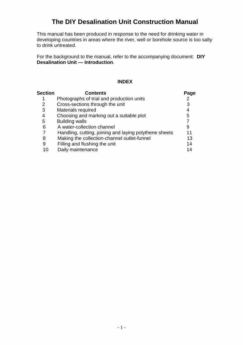
INDEX
Section Contents Page 1 Photographs of trial and production units 2 2 Cross-sections through the unit 3 3 Materials required 4 4 Choosing and marking out a suitable plot 5 5 Building walls 7
6 A water-collection channel 9 7 Handling, cutting, joining and laying polythene sheets 11 8 Making the collection-channel outlet-funnel 13 9 Filling and flushing the unit 14 10 Daily maintenance 14
- 2 -
1. Photographs of trial and production units
The main photograph shows a completed production unit. Water condensing on the underside of the polythene runs down to a collection channel that drains to a container below the low point of the channel. The three photographs at the top show earlier trial units under construction. The design of the collection channel shown was later modified to that illustrated on the cross-sections in section 2.
- 3 -
2. Cross-sections through the desalination unit
- 4 -
3. Materials required A polythene sheet
Affordable rolls of polythene sheet are required in two colours, black and clear, around 1.5 m wide (54 inches). The length required will depend on the size of filter being constructed. (Trial units in the south of Pakistan have produced yields of up to two litres a day per metre length of unit.) Sufficient length must be allowed for placing over the sloping walls at each end of the unit.
Other items needed:
A normal paper stapler
Two or three boxes of staples
Scissors
Fishing-line or string
An empty mineral-water bottle
Insulation tape
A drinking-water container
A shovel or other hand-digging tools
A sack of old newspapers
Bricks
Small stones
A tape measure
A bucket
A clean rag
- 5 -
4. Choosing and marking out a suitable plot Mark on the ground the outline of the unit of your chosen size, using fishing- line, string or narrow strips of polythene sheeting secured with sticks pushed into the ground. The sloping side should face south in the Northern hemisphere (or north in the Southern hemisphere) so that it faces the sun for the maximum time possible. See section 5 for further setting-out details.
Plots for a village can be laid out together in an enclosure like an allotment garden with a low thorn hedge to keep out animals.
Be sure that the unit is not in a hollow so that rain-water does not flood it. If water remains in contact with mud walls, they will soften and could collapse, as shown in this photograph. There is also a danger that flood water may enter and pollute or dislodge the clean-water container.
If the unit is to work properly, the ground under the unit must not slope or vary more than an inch in level from one end to the other.
Levelling the ground can be achieved by using sticks knocked into the ground with fishing-line pulled tight between them about 1 foot above the ground. Low points can then be filled and high points excavated until the ground is parallel with the line.
Both ends can be made the same level by using a water level. This is a thin, clear length of flexible pipe with water in it. More details of this and the levelling procedure are described below.
- 6 -
Diagram of a water level using a clear plastic tube
It is good for each village to have a water level so people can borrow it for levelling their plots.
If the hose is laid from stick to stick, without kinks in it and with its ends up, the water level in the pipe at both ends should naturally be the same. This fact can be used to adjust the position of the fishing-line so it is at the same level on both sticks.
With the fishing-line tight, another stick can be used as a dip-stick against the wire at any position along its length to check how much variation there is in the
ground level below the fishing-line.
If the plot is not accurately levelled, it will not be possible to fill the evaporation basin properly. If one end is lower than the other, water will gravitate towards the lower end and may overflow there or evaporate completely at the other end, reducing the surface area available for evaporation.
A water level using polythene sheeting
If a pipe suitable to use as a water level is not available, it is possible to check that a line on the ground is level by using a strip of polythene. To do this, make a groove in the ground and fit in it a continuous strip of polythene sheet. Put a little water in the strip of polythene. If the groove has a continuous line of water in it, the surface of the water at each end of the groove can be used as a level indicator.
- 7 -
5. Building walls
Build a wall 4m to 10m long and 24 inches high. It should be strong enough not to fall down when leant on, and thick enough to allow bricks to be securely placed on top. A maximum of 10m is suggested, as it would be difficult to ensure a constant fall along collection channels for longer units without the collection channel becoming too deep and needing too much of the polythene’s width to line it.
Thirty-six inches from the south edge of the 24-inch high wall (or the north edge if in the Southern hemisphere), peg out a string for the front edge of the evaporation basin and the north edge of the low wall shown on the diagram.
Make the north edge of the low wall 3.5 inches high along the full length of the unit. This low wall should be 3-4 inches and sloping gently down towards the south (or the north if in the Southern hemisphere) so any condensation dripping on it from the roof will run forwards into the water-collection channel.
Make a parallel wall 5 inches high along the full length of the unit immediately south of the collection channel (or north if in the Southern hemisphere). The 5-inch high wall should be 3-4 inches wide and sloping gently down towards the north (or the south if in the Southern hemisphere) so condensation will run backwards into the water-collection channel.
Details of the construction of the water-collection channel are described in section 7.
- 8 -
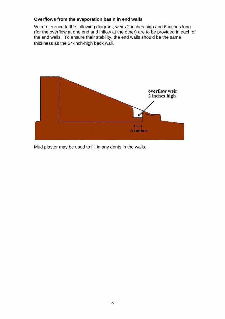
Overflows from the evaporation basin in end walls
With reference to the following diagram, weirs 2 inches high and 6 inches long (for the overflow at one end and inflow at the other) are to be provided in each of the end walls. To ensure their stability, the end walls should be the same
thickness as the 24-inch-high back wall.
Mud plaster may be used to fill in any dents in the walls.
- 9 -
6. The water-collection channel
A water-collection channel is to be formed between the 3.5-inch-high and 5-inch-high walls described in section 5. The channel is to be 1 inch deep at each end of the unit, increasing by 1 inch per metre to up to 6 inches deep at the outlet at the centre of the unit.
The water-collection channel can be constructed by using pegs and fishing-line and the water-level pipe as follows:
First knock a stick into the ground at each end of the channel.
Then, using the water-level pipe, mark a line on each stick at the same level, approximately 12 inches above the ground.
Mark a second line on each stick 10 inches below the first lines marked.
Pull a fishing wire tight between the two sticks from the top mark on one to the bottom mark on the other.
Make a depth-measuring stick. To do this, at the high end of the line, stand a straight stick upright on top of the southern wall (or the northern wall if in the Southern hemisphere). Snap it off so that it stands about 1 inch above the fishing-line.
Dig the water-collection channel from the end to the middle of the unit so that this stick just fits under the fishing line and the channel falls gradually and evenly towards the middle.
- 10 -
Change the position of the fishing wire to the other two marks on the sticks and make the other half of the drip-collection channel so it also slopes gradually and evenly towards the middle of the unit.
Dig a hole in the middle of the unit to the south of the evaporation pan (or to the north if in the Southern hemisphere).
Make it big enough for a water canister and deep enough for the canister and funnel to fit below the drip-collection channel at its deepest point.
- 11 -
7. Handling, cutting, joining and laying polythene sheets
The desalination-unit construction process described in this manual is based on use of a polythene-sheet width of 54 inches. The unit described can be cleaned and constructed easily and has been shown to work efficiently in practice. Sheets of different widths up to 54 inches will need to be cut or jointed to construct a similar unit. Different-size units can be constructed; however, care should be taken to ensure they are not too wide to clean. Also, the slope of the polythene sheet should be optimised so that condensation water is transferred to the collection channel efficiently. If the slope is too shallow, the condensation will fall back into the basin. If it is too steep, the condensation process will be less efficient and less water will be produced.
Be sure to wrap up any polythene sheets being transported home from the market in cloth or a piece of thick polythene to prevent it from snagging. Before placing any polythene sheeting, sweep out the evaporation pan and water-collection channel if necessary. All surfaces must be smooth and flat before laying the polythene sheeting.
Cut the plastic to the necessary length, making sure you have plenty for the east and west ends of the unit.
Wait for a time when it is not too windy to handle plastic. Take every precaution necessary to prevent the sheets from being snagged.
Cut off any crinkly edges that may have been made when the plastic was produced. Just a tiny strip should be sufficient.
Cut one sheet of clear polythene into two, one half to be 24 inches wide and the other 29 inches wide.
Using a normal paper stapler, fold and staple seams as illustrated on the diagram above. Have two or three boxes of staples at the ready.
- 12 -
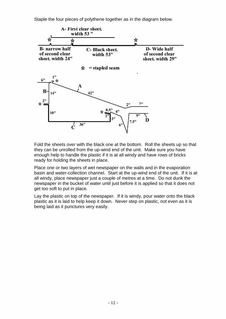
Staple the four pieces of polythene together as in the diagram below.
Fold the sheets over with the black one at the bottom. Roll the sheets up so that they can be unrolled from the up-wind end of the unit. Make sure you have enough help to handle the plastic if it is at all windy and have rows of bricks ready for holding the sheets in place.
Place one or two layers of wet newspaper on the walls and in the evaporation basin and water-collection channel. Start at the up-wind end of the unit. If it is at all windy, place newspaper just a couple of metres at a time. Do not dunk the newspaper in the bucket of water until just before it is applied so that it does not get too soft to put in place.
Lay the plastic on top of the newspaper. If it is windy, pour water onto the black plastic as it is laid to help keep it down. Never step on plastic, not even as it is being laid as it punctures very easily.
- 13 -
8. Making the collection-channel outlet funnel
Cut the top off a plastic mineral-water bottle and squash it to make a funnel so it fits over the polythene sheet at the outlet of the water-collection channel as shown in the diagram above.
Using scissors, cut a small round hole at the middle of the water-collection channel. N.B. Practise this on a small piece of polythene first.
Take a washed-smooth straight twig or piece of stiff wire 4 inches long and tie a strip of clean plastic bag 1 inch wide around its middle.
Thread the strip of plastic bag through the hole, the wide end of the funnel and the neck of the funnel.
Fold it back over the funnel neck and bind it tight with string or insulation tape. If available, a short piece of wide hose could be fitted over the neck of the funnel.
Fit the funnel into the water container with the funnel neck inside the neck of the canister. The fit should not be too tight, so as to ease the emptying and replacement procedure. Make sure the fit is tight enough to prevent insects from entering the water container as they will be attracted to standing water and may become a source of disease.
Put stones under the water container so it is supported and stable when full.
To keep the container clean, put it in a bucket or line the hole with polythene.
Make sure the hole is covered so that the container is in the dark and the drinking water can cool.
- 14 -
9. Filling and flushing the unit
To prevent a build-up of salt in the evaporation basin, each day, pour in approximately twice as much water as has evaporated.
If the raw water can normally be used for watering plants, it is unlikely that water overflowing from the overflow weir will be unsuitable for irrigation.
10. Daily maintenance
Polythene sheets need to be checked twice a day to make sure they are kept tight and are not flapping in the wind. In changing weather conditions, more regular checks will be necessary.
The outside clear-polythene sheet needs to be wiped clean with a clean cloth once a day to remove dust, which reduces the sunlight entering and could speed the decomposition of the polythene.
The drinking-water container needs emptying regularly. The frequency of the emptying will depend on its size and the amount of condensation water produced.