68
The Drive & Control Company Precision Modules PSK R310EN 2414 (2008.03)
| Date post: | 12-Mar-2018 |
| Category: |
Documents |
| Upload: | phungthuan |
| View: | 216 times |
| Download: | 3 times |

The Drive & Control Company
Precision Modules PSK R310EN 2414 (2008.03)

Bosch Rexroth AG
Linear Motion and Assembly Technologies
www.boschrexroth.com/brl
Ball Rail SystemsRoller Rail SystemsLinear Bushings and ShaftsBall Screw DrivesLinear Motion SystemsBasic Mechanical ElementsManual Production SystemsTransfer Systems

3Bosch Rexroth AGPrecision Modules PSKR310EN 2414 (2008.03)
Product Description 4
Product Overview 6
Motor selection 6
Overview of types with load capacities 8
Dimensions 9
Structural Design 10
PSK without cover 10
PSK with cover plate 10
PSK with sealing strip 11
Attachments for all PSK modules 11
Technical Data 14
Technical Data, Calculations 20
Calculation Example 23
Accuracy 25
Precision Module PSK 40 26
Components and Ordering Data 26
Lengths and Hole Spacing 28
Dimension Drawings without Cover 29
Dimension Drawings with Cover Plate 30
Dimension Drawings, Motor Attachment 31
Precision Module PSK 50 32
Components and Ordering Data 32
Lengths and Hole Spacing 34
Dimension Drawings without Cover 35
Dimension Drawings with Cover Plate 36
Dimension Drawings with Sealing Strip 37
Dimension Drawings, Motor Attachment 38
Precision Module PSK 60 40
Components and Ordering Data 40
Lengths and Hole Spacing 42
Dimension Drawings without Cover 43
Dimension Drawings with Cover Plate 44
Dimension Drawings with Sealing Strip 45
Dimension Drawings, Motor Attachment 46
Präzisionsmodul PSK 90 48
Components and Ordering Data 48
Lengths and Hole Spacing 50
Dimension Drawings without Cover 51
Dimension Drawings with Cover Plate 52
Dimension Drawings with Sealing Strip 53
Dimension Drawings, Motor Attachment 54
Precision Modules PSKSwitch Mounting Arrangements 56
Motors 59
AC Servo Motors MSK 59
AC Servo Motors MSM 60
3-phase Stepping Motors VRDM 61
Mounting 62
Lube Ports 63
Documentation 64
Inquiry/Order Form 67

4 Bosch Rexroth AG Precision Modules PSK R310EN 2414 (2008.03)
Outstanding features
Rexroth Precision Modules are precise, ready-to-install linear motion systems that combine high performance with compact dimensions.Rexroth offers favorable price/performance ratios and fast delivery.
Structural designExtremely compact and rigid precision steel profi le (frame) with reference edge and integrated Rexroth guideway geometryPrecision ball screw drive in tolerance grade 7 with zero-backlash nut systemAluminum fi xed bearing end block with preloaded ball bearings and ball screw journalFloating bearing end block with double ball bearingsOne or two steel carriages, standard length or long, for PSK without cover or with cover plateOne aluminum carriage, standard length or long, for PSK with sealing strip
AttachmentsMaintenance-free digital AC servo drives with integrated brake and attached feedback, or stepping motorsMotor mount and coupling or timing belt side drive for motor attachmentAdjustable switches over the entire travel rangeAluminum profi le cable duct
Drive controllers and control systems
–
–
–
––
–
–
–
––
Product Description
Fixed bearing end block with integrated motor mount
For mounting, maintenance and start-up, see “Instructions for Precision Modules PSK.”
Further highlights
Extremely stiff and precise miniature drive unitOptimal travel performance, high load capacities, high precision and high rigidity due to integrated Rexroth Ball Rail SystemHigh positioning accuracy and repeatability due to Precision Ball Screw Assembly with zero-backlash nut systemRepeatability up to 0.005 mmPositioning accuracy up to 0.01 mmGuidance accuracy up to 0.005 mmHigh travel speeds combined with high precision due to Ball Rail Systems, large screw diameters and leads, and double fl oating bearingRapid mounting and easy axis alignment thanks to machined reference edge on the framePrecise alignment and secure mounting of attachments thanks to tapped bores and pin holes in the carriageEasy motor attachment via locating feature and fastening threadsLow-cost maintenance provided by one-point lubrication (grease) for Ball Rail System and Precision Ball Screw AssemblyPrecision Modules in standard lengths for fast delivery
––
–
–
–
–
–
–
–
–
Fixed bearing end block with ball screw journal

5Bosch Rexroth AGPrecision Modules PSKR310EN 2414 (2008.03)
Internal elements protected by cover plateOne or two steel carriages, standard length or long
Internal elements protected by stainless steel sealing stripAluminum carriage, standard length or long
PSK without cover

6 Bosch Rexroth AG
RS232
Auto
Hand
Precision Modules PSK R310EN 2414 (2008.03)
Product OverviewMotor selection
Based on drive controllers and control system
A choice can be made between several different motor/controller combinations to achieve the most cost-effi cient solu-tion for each customer application.When sizing the drive, always consider the motor-controller combination.For more information about motors and control systems, see the following Rexroth catalog:
IndraDrive for Linear Motion Systems–
Digital AC servo motors MSK Digital controllers
IndraDrive
3-phase stepping motors VRDMPower electronics
Twin Line
Profi Step
control unit
Digital controllers
ECODRIVE Cs
Digital AC servo motors MSM
SD326SD328

7Bosch Rexroth AGPrecision Modules PSKR310EN 2414 (2008.03)
Precision Modules PSK can be supplied complete with motor, controller and control unit.

8 Bosch Rexroth AG Precision Modules PSK R310EN 2414 (2008.03)
Type designation(size)
Precision Modules are designated according to type and size.Types also cover the equivalent designs without drive systems.
All Precision Modules can also be supplied without drive unit.1)
Type System Guideway Drive unit 1) Size Cover Carriage (carr.) Load capacities
Number C(N)
PSK Precision Module Rail SystemPrecision Ball Screw Assembly
PSK 40Without / cover plate
Standard1 carr. 3 0652 carr. 4 980
PSK 50
Without / cover plate
Standard1 carr. 7 3002 carr. 11 850
Sealing stripStandard 1 carr. 7 300Long 1 carr. 11 850
PSK 60
Without / cover plate
Standard1 carr. 7 3002 carr. 11 850
Long1 carr. 9 0002 carr. 14 620
Sealing stripStandard 1 carr. 9 000Long 1 carr. 14 620
PSK 90
Without / cover plate
Standard1 carr. 21 3002 carr. 34 600
Long1 carr. 27 5002 carr. 44 670
Sealing stripStandard 1 carr. 21 300Long 1 carr. 34 600
Product OverviewDescription Type Size
Example: Precision Module P S K 60System Precision Module (P)Guideway Integrated Ball Rail System (S)Drive unit Precision Ball Screw Assembly (K)Frame size
B
Approx. width of frame (mm)Example: B = 60 mm
Permissible loads Suitable loads(recommended values)With respect to the desired service life, loads up to about 20% of the charac-teristic dynamic values (C, Mt, ML ) have proved acceptable.
At the same time, the following may not be exceeded:
maximum permissible loadspermissible drive torquepermissible travel speed
For permissible values, see the “Technical Data” section.
–––
Overview of types with load capacities

9Bosch Rexroth AG
H
B
C
C
C LC
Precision Modules PSKR310EN 2414 (2008.03)
Precision Module PSK 40 PSK 50 PSK 60 PSK 90B (mm) 40 50 60 86H (mm) 20 26 33 46L (mm) 100 100 150 340
150 150 200 440200 200 250 540250 250 300 640300 300 400 740350 350 500 840
400 600 940450 700500 800550 900600 940
Standard lengths L
Dimensions

10 Bosch Rexroth AG
1
2
3
4
5
6
7
9
8
Precision Modules PSK R310EN 2414 (2008.03)
Fixed bearing end blockBall screw with zero-backlash cylindrical single nutOne or two steel carriages, standard length or longFloating bearing end blockFrame with reference edge and integrated guideway geometry
12345
Cover plateOne or two carriages, standard length or longCarriage plate, aluminumCarriage plate guide unit, steel
6789
Structural Design
2 carriages, standard length
1 carriage, long
2 carriages, long
1 carriage, standard length
2 carriages, standard length
1 carriage, long
2 carriages, long
1 carriage, standard length
PSK with cover platePSK without cover

11Bosch Rexroth AG
10
11
13
1215
14
16
Precision Modules PSKR310EN 2414 (2008.03)
Sealing strip, stainless steelOne carriage, standard length or longCarriage plate, aluminumCarriage plate guide unit, aluminum
10111213
SwitchesCable ductSwitching cam
141516
1 carriage, long
1 carriage, standard length
PSK with sealing strip Attachments for all PSK modules

12 Bosch Rexroth AG
1
2
3
1
2
3
4
1
2
1
6
1 6 3 4 5
1 2 3 5
A B
Precision Modules PSK R310EN 2414 (2008.03)
Motor attachment
Motor attachment with motor mount and couplingA motor can be attached to all Precision Modules by means of a motor mount and coupling.The motor mount serves to fasten the motor to the Precision Module and acts as a closed housing for the coupling. The coupling transmits the motor drive torque free of distortive stresses to the Precision Module’s ball screw journal.
Fixed bearing end block with inte-grated motor mount and coupling
Motor2 Fixed bearing end block
with integrated motor mount3 Coupling5 Precision module
1
Structural Design
Fixed bearing end block with attached motor mount and coupling1 Motor3 Coupling4 Fixed bearing end block5 Precision module6 Motor mount
Fixed bearing end block
Version with ball screw journal (A)End block with preloaded bearingTapped mounting holeCentering feature
Version with integrated motor mount (B)
End block with integrated motor mount and preloaded bearingTapped mounting holeCentering featureFlange form suitable for motor attachment
123
1
234

13Bosch Rexroth AG
Fpr
6
5
4
7
1
9
8
5
2
2
9
1
3
2
5
Precision Modules PSKR310EN 2414 (2008.03)
Motor attachment with timing belt side driveOn Precision Modules PSK 60 and PSK 90 the motor (9) can be attached via a side drive with timing belt.This makes the overall length shorter than when attaching the motor with a motor mount and coupling.The compact, closed housing protects the belt and secures the motor.
The following gear ratios are available:i = 1 : 1i = 1 : 1.5
The timing belt side drive can be mounted in four different directions:
top, bottomleft, right
Precision moduleEnd coverCover plateDrawn, anodized aluminum profi leBall screw journal with support bearingToothed beltPre-tensioning of the toothed belt:Apply pretensioning force Fpr to motor (Fpr will be indicated on delivery)Belt pulleysAC servo motor
––
12345
67
89

14 Bosch Rexroth AG
yy
z
z
Precision Modules PSK R310EN 2414 (2008.03)
Technical DataDynamic characteristics
Precision Module
Planar moment of inertia
Minimum center-to-center distance lm min
Mass of the linear motion system ms (kg)
Iy Iz Standard carr. Long carr. Without cover, without drive
Without cover, with drive
With cover plate
With sealing strip
(cm4) (cm4) (mm) (mm)PSK 40 0.892 6.65 50 – 0.0026 · L + mca 0.0028 · L
+ 0.075 + mca
0.0030 · L + 0.089 + mca
–
PSK 50 1.690 13.50 60 – 0.0035 · L + mca 0.0038 · L + 0.179 + mca
0.0041 · L + 0.204 + mca
0.0042 · L + 0.208 + mca
PSK 60 5.380 34.48 60 75 0.0062 · L + mca 0.0069 · L + 0.254 + mca
0.0072 · L + 0.281 + mca
0.0073 · L + 0.272 + mca
PSK 90 22.340 145.80 90 110 0.0125 · L + mca 0.0138 · L + 0.638 + mca
0.0146 · L + 0.726 + mca
0.0147 · L + 0.736 + mca
General technical data
MassMass calculation without motor and switches.Mass formula:Mass factor (kg/mm) · length L (mm) + mass of all parts of fi xed length (kg) + moved mass of system mca (kg)
Modulus of elasticity E E = 210,000 N/mm2
Precision Module
Type of cover
Carriage (carr.) Guideway Ball screw Fixed bearingNumber Dynamic
load capacity Dynamic load moments Size Dynamic
load capacityDynamic
load capacityC
(N)Mt
(Nm)ML
(Nm)d0 x P C
(N)C
(N)PSK 40 W/o and
w/plateStandard 1 carr. 3 065 43.1 14.8 6 x 1 900 820
2 carr. 4 980 70.0 2.49 x lm 6 x 2 890 820PSK 50 W/o and
w/plateStandard 1 carr. 7 300 150.0 35 8 x 2.5 2 200 1 600
2 carr. 11 850 244.0 5.93 x lm 8 x 2.5 2 200 1 600Strip Standard 1 carr. 7 300 150.0 35 8 x 2.5 2 200 1 600
Long 1 carr. 11 850 244.0 356 8 x 2.5 2 200 1 600PSK 60 W/o and
w/plateStandard 1 carr. 7 300 170.0 35 12 x 2 2 240 4 000
2 carr. 11 850 276.0 5.93 x lm 12 x 2 2 240 4 000Long 1 carr. 9 000 210.0 60 12 x 5 3 800 4 000
2 carr. 14 620 341.0 7.31 x lm 12 x 5 3 800 4 000Strip Standard 1 carr. 9 000 210.0 60 12 x 10 2 500 4 000
Long 1 carr. 14 620 341.0 541 12 x 10 2 500 4 000PSK 90 W/o and
w/plateStandard 1 carr. 21 300 710.0 150 16 x 5 12 300 13 400
2 carr. 34 600 1153.0 17.3 x lm 16 x 5 12 300 13 400Long 1 carr. 27 500 910.0 270 16 x 10 9 600 13 400
2 carr. 44 670 1478.0 22.34 x lm 16 x 10 9 600 13 400Strip Standard 1 carr. 21 300 710.0 150 16 x 16 6 300 13 400
Long 1 carr. 34 600 1153.0 1557 16 x 16 6 300 13 400
lm = center-to-center distance between carriages (mm)d0 = screw diameter (mm)P = screw lead (mm)carr. = carriage(s) (mm)mca = moved mass of system (kg)

15Bosch Rexroth AG
y
x
z
M z max
M L /
Mx max
l m
Mt/
Fz max
My max
ML /F
y max
Precision Modules PSKR310EN 2414 (2008.03)
Note on dynamic load capacities and momentsDetermination of the dynamic load capacities and moments is based on a travel life of 100,000 m.Often only 50,000 m are actually stipulated.For comparison: Multiply values C, Mt and ML from the table by 1.26.
Moved mass of system mca
Maximum permissible loadsThe maximum permissible forces (Fy max, Fz max) and moments (ML max, Mt max) are equal to half the dynamic characteristics (C, Mt, ML).
Precision Module
Carriage Moved mass of system mca (kg)Without cover, without drive
Without cover, with drive
With cover plate With sealing strip
1 carr. 2 carr. 1 carr. 2 carr. 1 carr. 2 carr. 1 carr. PSK 40 Standard 0.08 0.17 0.09 0.18 0.14 0.28 –PSK 50 Standard 0.20 0.40 0.22 0.42 0.29 0.56 0.20
Long – – – – – – 0.37PSK 60 Standard 0.25 0.49 0.27 0.52 0.38 0.73 0.33
Long 0.34 0.69 0.37 0.71 0.51 1.00 0.58PSK 90 Standard 0.77 1.54 0.85 1.62 1.09 2.10 0.80
Long 1.04 2.08 1.11 2.15 1.43 2.79 1.40
Suitable loads(recommended values)With respect to the desired service life, loads up to about 20% of the charac-teristic dynamic values (C, Mt, ML ) have proved acceptable.At the same time, the following may not be exceeded:
maximum permissible loadspermissible drive torquepermissible travel speed
–––
lm = center-to-center distance between carriages (mm)
carr. = carriage(s) (mm)
16 Bosch Rexroth AG
0,05
0,15
0,10
0,30
0,00100 150 200 250 300 350
0,20
0,25
Mm
ech
(Nm
)
L (mm)
6x1
100
0,4
0,2
0,6
0,8
1,0
1,2
0,0200 300 400 500 600
Mm
ech
(Nm
)
L (mm)
0,5
1,0
1,5
2,0
0,0200 300 400 500 600 700 800 900100
L (mm)
Mm
ech
(Nm
)
12x5
12x2
1
2
3
4
5
6
0200 300 400 500 600 700 800 900
Mm
ech
(Nm
)
L (mm)100
16x10
16x5
PSK 60
PSK 90
PSK 40
PSK 50
Precision Modules PSK R310EN 2414 (2008.03)
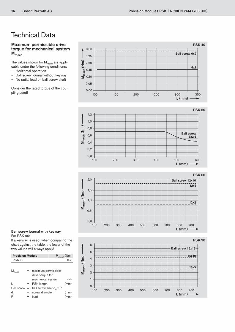
Maximum permissible drive torque for mechanical system Mmech
The values shown for Mmech are appli-cable under the following conditions:
Horizontal operationBall screw journal without keywayNo radial load on ball screw shaft
Consider the rated torque of the cou-pling used!
–––
Ball screw journal with keywayFor PSK 90:If a keyway is used, when comparing the chart against the table, the lower of the two values will always apply!
Technical Data
Precision Module Mmech (Nm)PSK 90 3.2
Mmech = maximum permissible drive torque for mechanical system (N)
L = PSK length (mm)Ball screw = ball screw size: d0 x Pd0 = screw diameter (mm)P = lead (mm)
Ball screw 12x10
Ball screw 16x16
Ball screw 6x2
Ball screw 8x2,5

17Bosch Rexroth AG
100 150 200 250 300 350
0,4
0,3
0,2
0,1
0
v mec
h (m
/s)
L (mm)
6x1
300 400 500 600200L (mm)
100
0,3
0,2
0,1
0
v mec
h (m
/s)
300 400 500 600 700 800200 900L (mm)
100
v mec
h (m
/s)
1,81,61,41,21,00,80,60,40,2
0
16x10
16x5
300 400 500 600 700 800200 900L (mm)
100
v mec
h (m
/s)
1,2
1,0
0,8
0,6
0,4
0,2
0
12x5
12x2
PSK 60
PSK 50
PSK 90
PSK 40
Precision Modules PSKR310EN 2414 (2008.03)
Maximum permissible linear speed of mechanical system vmech
Consider the motor speed!
vmech = maximum permissible linear speed of mechanical system (m/s)
L = PSK length (mm)Ball screw = ball screw size: d0 x Pd0 = screw diameter (mm)P = lead (mm)
Ball screw 6x2
Ball screw 8x2,5
Ball screw 12x10
Ball screw 16x16

18 Bosch Rexroth AG Precision Modules PSK R310EN 2414 (2008.03)
Drive data of timing belt side drive, fi xed bearing end for motor attachment via timing belt side drive
Technical Data
Motor type MSM 030B / MSM 030C / MSK 030C MSM 040B / MSK 040CFrictional torque MRsd (Nm) 0.35 0.4
Permissible torque up to length L = ... at
Reduced mass moment of inertia at
Permissible torque up to length L = ... at
Reduced mass moment of inertia at
Gear ratio i = 1 i = 1.5 i = 1 i = 1.5 i = 1 i = 1.5 i = 1 i = 1.5Precision Module
Ball screw size L Msd Msd Jsd Jsd L Msd Msd Jsd Jsd
d0 x P (mm) (Nm) (Nm) (10-6 kgm2) (10-6 kgm2) (mm) (Nm) (Nm) (10-6 kgm2) (10-6 kgm2)PSK 60 12 x 2 940 0.80 0.50 45.6 17.7 – – – – –
12 x 5 940 1.60 1.10 45.6 17.7 – – – – –12 x 10 940 1.60 1.10 45.6 17.7 – – – – –
PSK 90 16 x 5 940 2.40 1.60 40.0 14.0 940 2.40 1.60 234 98.916 x 10 940 2.50 1.70 40.0 14.0 940 3.90 2.60 234 98.916 x 16 940 2.50 1.70 40.0 14.0 940 4.80 3.20 234 98.9
Frictional torque of the linear motion system MRs
Precision Module Frictional torque of the linear motion system MRs (Nm) for carriage versionBall screw sized0 x P
Without cover or with cover plate1 carr. or 2 carr.
With sealing strip 1 carr. or 2 carr.
Standard Long Standard LongPSK 40 6 x 1 0.033 – – –
6 x 2 0.034 – – –PSK 50 8 x 2.5 0.10 – 0.10 0.11PSK 60 12 x 2 0.12 0.12 0.12 0.13
12 x 5 0.13 0.14 0.14 0.1512 x 10 0.15 0.16 0.16 0.18
PSK 90 16 x 5 0.30 0.31 0.30 0.3116 x 10 0.30 0.33 0.32 0.3516 x 16 0.31 0.37 0.34 0.39
carr. = carriage(s) (mm)d0 = screw diameter (mm)P = screw lead (mm)
d0 = screw diameter (mm)P = screw lead (mm)
MRsd = frictional torque of timing belt side drive at motor journal (Nm)Msd = maximum permissible drive torque of the timing belt side drive (Nm); consider the maximum torque of the motor Mmax
Jsd = mass moment of inertia of timing belt side drive (kgm2)i = timing belt side drive reduction

19Bosch Rexroth AG
Js = (kJ fi x + k J var . L) . 10–6
Precision Modules PSKR310EN 2414 (2008.03)
Coupling data
Js = mass moment of inertia of linear motion system (without external load) (kgm2)
kJ fi x = constant for fi xed-length portion of mass moment of inertia (106 kgm2)
kJ m = constant for mass-specifi c portion of mass moment of inertia (106 kgm2)
kJ var = constant for variable-length portion of mass moment of inertia (109 kgm)
L = length (mm)
Precision Module
kJ fi x kJ var kJ m
Ball screw size
Carriage Without cover Cover plate Sealing strip
d0 x P 1 carr. 2 carr. 1 carr. 2 carr. 1 carr.PSK 40 6 x 1 Standard 0.115 0.117 0.116 0.120 – 0.002 0.025
6 x 2 Standard 0.122 0.131 0.127 0.141 – 0.002 0.101PSK 50 8 x 2,5 Standard 0.533 0.565 0.544 0.587 0.530
0.004 0.158Long – – – – 0.557PSK 60 12 x 2 Standard 0.999 1.024 1.010 1.045 1.005
0.013 0.101Long 1.009 1.043 1.023 1.073 1.03012 x 5 Standard 1.130 1.289 1.200 1.422 1.168
0.011 0.633Long 1.194 1.409 1.282 1.593 1.32712 x 10 Standard 1.643 2.277 1.922 2.808 1.795
0.011 2.533Long 1.897 2.758 2.251 3.492 2.492PSK 90 16 x 5 Standard 4.216 4.703 4.368 5.007 4.184
0.031 0.633Long 4.216 4.703 4.368 5.007 4.18416 x 10 Standard 5.831 7.781 6.439 8.997 5.704
0.031 2.533Long 6.489 9.124 7.300 10.745 7.22416 x 16 Standard 9.213 14.207 10.770 17.319 8.889
0.034 6.485Long 10.899 17.643 12.974 21.793 12.780
Precision Module
Coupling datafor motor attachment
Rated torque
McN
Mass moment of inertia
Jc
Weight
mc(Nm) (10–6 kgm2) (kg)
PSK 40 MSM 020B 0.70 0.12 0.015PSK 50 MSM 020B 1.90 2.10 0.040
MSM 030B 3.70 7.00 0.075MSK 030C 3.70 7.00 0.075VRDM 368 3.70 7.00 0.075
PSK 60 MSM 030B 3.70 7.00 0.075MSK 030C 1.90 2.10 0.040VRDM 368 5.50 20.00 0.040
PSK 90 MSM 030C 10.00 35.00 0.170MSM 040B 9.00 60.00 0.260MSK 030C 10.00 35.00 0.170MSK 040C 9.00 60.00 0.260VRDM 3910 9.00 60.00 0.260VRDM 397 9.00 60.00 0.260
Mass moment of inertia of the linear motion system Js referred to the drive journal

20 Bosch Rexroth AG
z1
y
x
z
M z
M L /
Mx
Mt/
Fz
Fy My
ML /
Mx
MtFcomb = Fy + Fz + C · + C · + C ·
My
ML
Mz
ML
Precision Modules PSK R310EN 2414 (2008.03)
Technical Data, Calculations
Combined equivalent load on bearing of the linear guide
Fcomb = combined equivalent load on bearing (N)Fy = force in y-direction (N)Fz = force in z-direction (N)Mx = torsional moment (about the x-axis) (Nm)My = torsional moment (about the y-axis) (Nm)Mz = torsional moment (about the z-axis) (Nm)C = dynamic load capacity (N)Mt = dynamic torsional moment load capacity (Nm)ML = dynamic longitudinal moment load capacity (Nm)
(1)
z1 = distance between guideway centerline and top edge of carriage (mm)
z1 (mm)Without cover Cover plate Sealing strip
PSK 40 11 23 –PSK 50 13 27 27PSK 60 17 32 32PSK 90 22 44 44

21Bosch Rexroth AG
Jex = + JsdJs + Jt
i2
Jex = Js + Jt + Jc
Jt = mex · kJm · 10-6
L = · 105 m CFcomb
3
L h = L
3600 · vm
MR = MRs
MR = + MR sdMRs
i
Precision Modules PSKR310EN 2414 (2008.03)
C = dynamic load capacity (N)Fcomb = combined equivalent load
on bearing (N)i = timing belt side drive
reduction (–)Jc = mass moment of inertia,
coupling (kgm2)Jex = mass moment of inertia
of mechanical system (kgm2)Js = mass moment of inertia
of linear motion system (without external load) (kgm2)
Jt = translatory mass moment of inertia of external load referred to the drive journal (kgm2)
kJm = constant for mass-specifi c portion of mass moment of inertia (106 m2)
L = nominal life (m)Lh = nominal life (h)mex = moved external load (kg)MR = frictional torque at motor
journal (Nm)MR sd = frictional torque of timing
belt side drive (Nm)MRs = frictional torque of linear
motion system (Nm)vm = average speed (m/s)
Nominal life Nominal life of the guideway in meters:
Frictional torqueFrictional torque for motor attachment via motor mount and coupling:
Mass moment of inertiafor motor attachment via motor mount and coupling:
for motor attachment via timing belt side drive:
Nominal life of the guideway in hours:
(3)
(4)
(2)
(6)
(7)
Translatory mass moment of inertia of external load referred to the drive journal
(8)
(5)
Frictional torque for motor attachment via timing belt side drive:

22 Bosch Rexroth AG
Jdc = Jex + Jbr
Jtot = Jdc + Jm
nmech =vmech · i · 1000 · 60
P
V = Jdc
Jm
Precision Modules PSK R310EN 2414 (2008.03)
Mass moment of inertia of the drive train referred to the motor journal
(8)
i = timing belt side drive reduction (–)
Jbr = mass moment of inertia, motor brake (kgm2)
Jdc = mass moment of inertia, drive train (kgm2)
Jex = mass moment of inertia of mechanical system (kgm2)
Jm = mass moment of inertia, motor (kgm2)
Jtot = total mass moment of inertia (kgm2)
nm max = maximum permissible rotary speed of motor with controller (min–1)
nmech = maximum permissible rotary speed of mechanical system (min–1)
P = screw lead (mm)V = ratio of mass moments
of inertia of drive train and motor (–)
vmech = maximum permissible linear speed of mechanical system (m/s)
Application area VHandling ≤ 6.0Machining ≤ 1.5
Mass moment of inertia ratio(9)
Technical Data, Calculations
Total mass moment of inertia referred to the motor journal (10)
Maximum permissible rotary speed for mechanical system (11)
Condition: nmech < nm max

23Bosch Rexroth AG
390 mm
L
m = 20 kg m = 20 kgF = 0 N
Precision Modules PSKR310EN 2414 (2008.03)
Given data
When sizing the drive, the motor-controller combination must always be considered, as the motor type and performance data (e.g. maximum useful speed and maximum torque) will depend on the controller or control system used.
A mass of 20 kg is to be moved 390 mm at a maximum travel speed of 0.6 m/s.
Estimation of the PSK module length L
Module selected based on the technical data and the connection dimensions:
PSK 90 without cover and with a standard length steel carriage; motor attachment via integrated motor mount and couplingMotor type MSK 030C
–
–
Excess travel = 2 . P = 2 . 16 mm = 32 mm (in accordance with the formula given in “PSK 90 Components and Ordering Data”)
Permissible ball screws according to the “Permissible travel speed” chart at vmech = 0.6 m/s: Ball screw 16x10 and 16x16;Ball screw selected: Ball screw 16x10 with vmech = 1 m/sMmech = 4.1 Nm with ball screw 16x10 (according to the chart “Maximum permissible drive torque”)
Selection of ball screw:As a general rule:Always choose the lowest lead (resolution, braking distance, length).
Excess travel = 2 . P = 2 . 10 mm = 20 mmLength L = (effective stroke + 2 . excess travel) + 100 mm =
(390 mm + 2 . 20 mm) + 100 mm = 530 mmSelected: Standard length L = 540 mm; hole spacing in frame: 70 mm / 4 . 100 mm / 70 mm
MR = MRsMR = 0.30 Nm (see “Technical Data”)
Calculation of PSK length L
Frictional torque MR
Calculation example

24 Bosch Rexroth AG
140,23 · 10–6 kgm2
30 · 10–6 kgm2
V =Jdc
Jm≤ 6
V = = 4,67 < 6
nmech = = = 3600 min–1v · i · 1000 · 6010
0,6m/s · 1 · 1000 · 60
10 mm
Precision Modules PSK R310EN 2414 (2008.03)
Calculation example (continued)Jex = Js + Jt + Jc
Js = (kJ fix + kJ var · L) = (5.831 + 0.031 · 540 mm) · 10–6
= 22.57 · 10–6 kgm2 (see “Technical Data”)
Jt = mex · kJ m · 10–6
= 20 kg · 2.533 · 10–6 kgm2
= 50.66 · 10–6 kgm2 (see “Technical Data”)
Jc = 60 · 10–6 kgm2 (see “Technical Data”)Jex = (22.57 + 50.66 + 60) · 10–6 kgm2
= 133.23 · 10–6 kgm2
Jdc = Jex + JbrJbr = 7.0 · 10–6 kgm2 (see “Motors”)Jdc = (133.23 + 7.0) · 10–6 kgm2
= 140.23 · 10–6 kgm2
Mass moment of inertia of mechanical system:
Precision Module PSK 90 without cover and with one standard-length steel carriage; Motor MSK 030C, attached via integrated mount and coupling:Standard length L = 540 mm; Hole spacing in frame: 70 mm / 40 · 100 mm / 70 mm
Ball screw 16 x 10 with vmech = 1 m/s > 0.6 m/s Mmech = 4.1 NmFrictional torque MR = 0.30 Nm
Motor MSK 030C:Mass moment of inertia Jm = 30 · 10–6 kgm2 ; V = 4,67 < 6Rotary speed nm max = 9000 min–1 > 3600 min–1
Torque Mmax = 4.0 Nm < 4.1 Nm
For final motor selection, the drive and performance data must be recalculated as specified in the Rexroth catalog “Control Systems, Electrical Accessories, ...”
Mass moment of inertia for handling (V ≤ 6):
Rotary speed n:
Result

25Bosch Rexroth AG
II P1
II P3 P3
246
81012141618
0200 300 400 500 600 700 800 900
L (mm)100
2468
1012141618
0200 300 400 500 600 700 800 900
L (mm)100
Precision Modules PSKR310EN 2414 (2008.03)
All accuracy fi gures apply to the module when screwed down and assume an ideally fl at mounting base. The values given do not take account of any shape deviations in the mounting base surface.
Accuracy P1
Measured at the carriage center
Accuracy P3
General note
Accuracy
Reference edge
lengthwise

26 Bosch Rexroth AG Precision Modules PSK R310EN 2414 (2008.03)
Part number, lengthR1465 100 00, .... mm
Guideway Drive unit Carriage versionSteel
Reference edge (RE) Screwjournal
Ball screw sized0 x P
Without cover Cover plate
Version Standard Standard
RE left RE right 6 x 1 6 x 2 1 carr. 2 carr. 1 carr. 2 carr.
With
out d
rive
OA01
OA01L = 100 mm
10
L = 150 mm12
L = 200 mm14
L = 250 mm16
L = 300 mm18
L = 350 mm20
without 50 01 02 – –
With
bal
l scr
ew,
w/o
mot
or m
ount
OF01
OF02
OF01OF02
Ø4 01 02 01 02 21 22
With
bal
l scr
ew a
nd
inte
grat
ed m
ount
MF10
MF11
MF10MF11
Ø4 30 31 01 02 21 22
Precision Module PSK 40 Components and Ordering Data
Ordering example: See “Inquiry/Order” form
Please check whether the selected combination is a permissible one (load capacities, moments, maximum speeds, motor data, etc.)!c
d0 = screw diameter (mm)P = screw lead (mm) carr. = carriage(s)L = length
RE
RE
RE
RE

27Bosch Rexroth AGPrecision Modules PSKR310EN 2414 (2008.03)
Motor attachment Motor Type of cover Switches / Cable duct / Socket-plug Documentation
Attachment kit 1) for motor with brake
without brake
without cover plate
Standard report
Measure-ment report
00 – 00 00 –Without switch and cable duct
00
Switches:
– Reed sensor– Hall sensor
21-...3)
22-...3)
Cable duct 27
Switching cam for PSK:– Without cover or
with cover plate35
01
02Friction moment
03Lead
deviation
04Travel
accuracy
05Positioning accuracy
00 – 00 00 01
30 NEMA 14-C2) 00
00 0131 NEMA 17-C2) 00
32 NEMA 17-D2) 00
34 MSM 020B 69 68
Attachment kit also available without motor (when ordering: enter “00” for motor).Use motors complying with the appropri-ate NEMA specifi cation.Because of the varying shaft dimensions for NEMA-specifi cation motors, the attach-ment kit does not include a coupling.Mounting side for switches: left (L) or right (R)
1)
2)
3)
Switch mounting arrangements
A mounting duct is required for installa-tion of the switches.
Refer to “Switch mounting arrange-ments” for more information on switch types and switch mounting.
Left (L)
Right (R)
Switches may only be mounted to one side of the Precision Module (left or right).

28 Bosch Rexroth AG
(T1)
L
N x T = ZT1 T
lm
Precision Modules PSK R310EN 2414 (2008.03)
For ISO 4762
Length L
Im = center-to-center distance between carriages (consider lm min )
Stroke = maximum travel of carriage center between the outermost switch activation points
ExampleBall screw 6 x 2(Ball screw size = d0 x P):Excess travel = 2 · 2 = 4 mm
In most cases the recommended limit for excess travel (braking path) is:Excess travel = 2 · screw lead P
Standard lengths of frame
Type of cover Number of carriages (carr.) Carriage versionStandard length
Without cover or with cover plate
1 carr. L = (stroke + 2 · excess travel) + 55 mm2 carr. L = (stroke + 2 · excess travel) + lm + 55 mm
lm min = 50 mm
Length L(mm)
T(mm)
T1
(mm)N Z
(mm)Mounting holes
for ISO 4762 screws100 60 20 1 60 M3150 60 15 2 120200 60 40 2 120250 60 35 3 180300 60 30 4 240350 60 25 5 300
Precision Module PSK 40 Lengths and Hole Spacing

29Bosch Rexroth AG
L/2
10 20
47,5
32
20
5
12,524
,5
(T1) 10
19,5
T = 60
19
L
N x 60 = Z
T1
Ø4 h
7
24
18
18
40
18
26,8
Ø3,4 1,6
17,7 20
Ø6
183
A
A
A-A
Precision Modules PSKR310EN 2414 (2008.03)
All dimensions in mmDrawings not to scale
Lube holeVersion:One or two carriages, standard length
Ø3H7–5 deep (2x)
M3–4.5 deep (4x)
Excess travel Excess travelEffective stroke / 2
Max. travel / 2
Effective stroke / 2
Max. travel / 2
Reference edgeM3–6 deep (4x)
Driving runner block
lm min = 50
Ø19H7–1.6 deep
Precision Module PSK 40 Dimension Drawings without Cover

30 Bosch Rexroth AG
L/2
8 8
10 20
46
20
12,524
,5
31,2
(T1) 10
19,5 31
,2
T = 60
19
L
N x 60 = Z
T1
Ø4
h7
24
18
18
40
18
52
37
Ø3,4 1,6
17,7 20
32
Ø6
45A
A
A-A
Precision Modules PSK R310EN 2414 (2008.03)
One-point lubrication (grease):via funnel-type lube nipples DIN 3405-D3 on both sides
lm min = 50
All dimensions in mmDrawings not to scale
Version:One or two carriages, standard length
Ø3H7–6 deep (2x)
M4–12 deep (4x)
Excess travel Excess travelEffective stroke / 2
Max. travel / 2
Effective stroke / 2
Max. travel / 2
Driving runner block
Reference edgeM3–6 deep (4x)
Ø19H7–1.6 deep
Precision Module PSK 40 Dimension Drawings with Cover Plate
31Bosch Rexroth AG
1,6
10
Ø4 h
7
20
Ø19
H7
12,5
Ø4 h
7
Ø19
Ø22
H7
Ø50,818,58
349 43
45
Ø4 h
7
Ø19
Ø22
H7
Ø3,3
Ø43,818,5
83
10
49 43
45
Ø4 h
7
Ø19
Ø22
H7
Ø3,3
Ø36,818,5
83
7
4935
45
D
Lm Lf
Precision Modules PSKR310EN 2414 (2008.03)
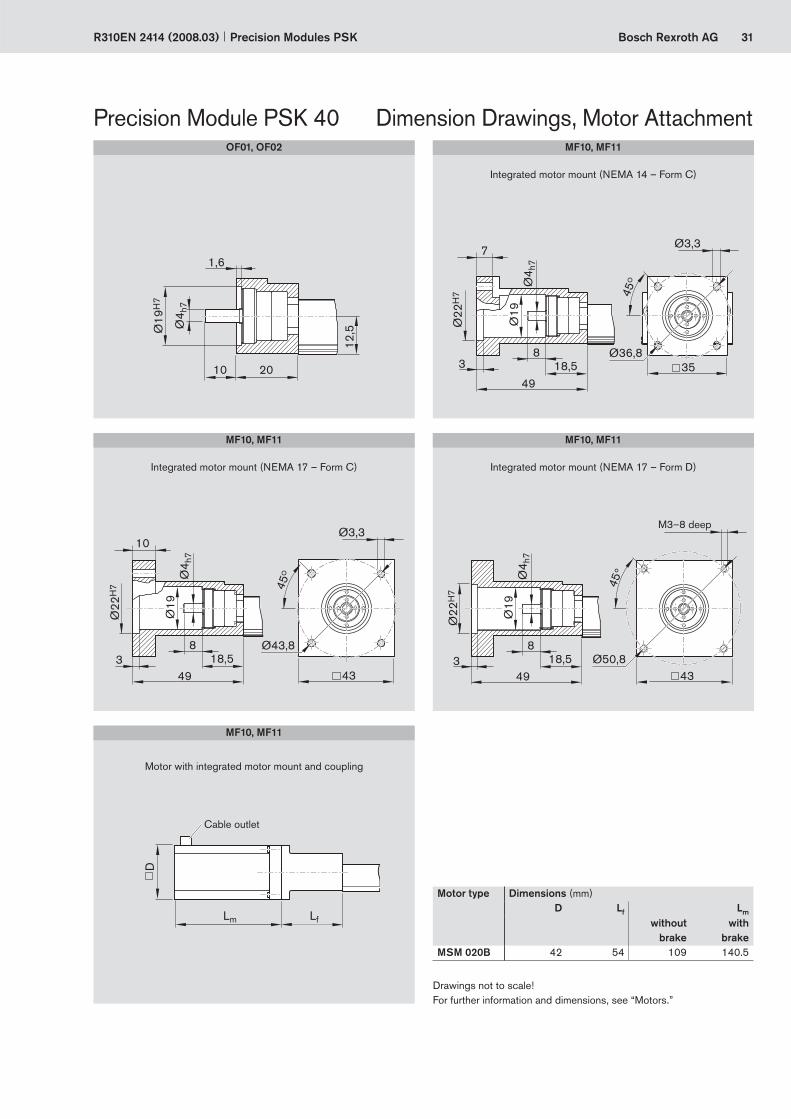
Integrated motor mount (NEMA 17 – Form C) Integrated motor mount (NEMA 17 – Form D)
M3–8 deep
Integrated motor mount (NEMA 14 – Form C)
Precision Module PSK 40 Dimension Drawings, Motor Attachment
Motor with integrated motor mount and coupling
Motor type Dimensions (mm)D Lf Lm
without brake
with brake
MSM 020B 42 54 109 140.5
Drawings not to scale! For further information and dimensions, see “Motors.”
MF10, MF11
Cable outlet
MF10, MF11 MF10, MF11
MF10, MF11OF01, OF02

32 Bosch Rexroth AG Precision Modules PSK R310EN 2414 (2008.03)
Part number, lengthR1465 200 00, .... mm
Guideway Drive unit Carriage versionSteel Aluminum
Reference edge (RE) Screwjournal
Ball screwsized0 x P
Without cover Cover plate Sealing strip
Version Standard Standard Stan-dard
Long
RE left RE right 8 x 2.5 1 carr. 2 carr. 1 carr. 2 carr. 1 carr. 1 carr.
With
out d
rive
OA01
OA01
L = 100 mm09
L = 150 mm10
L = 200 mm11
L = 250 mm12
L = 300 mm13
L = 350 mm14
L = 400 mm15
L = 450 mm16
L = 500 mm17
L = 550 mm18
L = 600 mm19
without 50 01 02 – – – –
With
bal
l scr
ew,
w/o
mot
or m
ount
OF01
OF02
OF01OF02
Ø5 01 01 02 21 22 40 41
With
bal
l scr
ew
and
mot
or m
ount
MF01
MF02
MF01MF02
Ø5 01 01 02 21 22 40 41
With
bal
l scr
ew a
nd
inte
grat
ed m
ount
MF10
MF11
MF10MF11
Ø5 30 01 02 21 22 40 41
Precision Module PSK 50 Components and Ordering Data
RE
RE
RE
RE
RE
RE
Ordering example: See “Inquiry/Order” form
Please check whether the selected combination is a permissible one (load capacities, moments, maximum speeds, motor data, etc.)!c
d0 = screw diameter (mm)P = screw lead (mm) carr. = carriage(s)L = length

33Bosch Rexroth AGPrecision Modules PSKR310EN 2414 (2008.03)
Motor attachment Motor Type of cover Switches / Cable duct / Socket-plug Documentation
Attachment kit 1)
for motor with brake
without brake
with-out
coverplate
strip Standard report
Measure-ment report
00 – 00 00 – –
Without switch and cable duct
00
Switches:
– Reed sensor– Hall sensor
21-...3)
22-...3)
Cable duct 26
Switching cam for PSK:– Without cover or
with cover plate– With sealing strip
32
34
01
02Friction moment
03Lead
deviation
04Travel
accuracy
05Positioning accuracy
00 – 00 00 01 02
01 MSM 030B 71 70
00 01 0203 MSK 030C 85 84
02 VRDM 368 36 35
31 NEMA 17-D2) 00
00 01 0235 NEMA 17-C2) 00
34 MSM 020B 69 68
Attachment kit also available without motor (when ordering: enter “00” for motor).Use motors complying with the appropri-ate NEMA specifi cation.Because of the varying shaft dimensions for NEMA-specifi cation motors, the attach-ment kit does not include a coupling.Mounting side for switches: left (L) or right (R)
1)
2)
3)
Switch mounting arrangements
A mounting duct is required for installa-tion of the switches.
Refer to “Switch mounting arrange-ments” for more information on switch types and switch mounting.
Left (L)
Right (R)
Switches may only be mounted to one side of the Precision Module (left or right).

34 Bosch Rexroth AG
(T1)
L
N x T = ZT1 T
lm
Precision Modules PSK R310EN 2414 (2008.03)
Precision Module PSK 50
Length L
In most cases the recommended limit for excess travel (braking path) is:Excess travel = 2 · screw lead P
Standard lengths of frame
Type of cover Number of carriages (carr.) Carriage versionStandard length Long
Without cover or with cover plate
1 carr. L = (stroke + 2 · excess travel) + 70 mm –2 carr. L = (stroke + 2 · excess travel) + lm + 70 mm
lm min = 75 mm–
With sealing strip 1 carr. L = (stroke + 2 · excess travel) + 127 mm L = (stroke + 2 · excess travel) + 187 mm
Length L(mm)
T(mm)
T1
(mm)N Z
(mm)Mounting holes
for ISO 4762 screws100 80 10 1 80 M4150 80 35 1 80200 80 20 2 160250 80 45 2 160300 80 30 3 240350 80 15 4 320400 80 40 4 320450 80 25 5 400500 80 50 5 400550 80 35 6 480600 80 20 7 560
Lengths and Hole Spacing
Im = center-to-center distance between carriages (consider lm min )
Stroke = maximum travel of carriage center between the outermost switch activation points
ExampleBall screw 8 x 2.5 (Ball screw size = d0 x P):Excess travel = 2 · 2.5 = 5 mm
For ISO 4762

35Bosch Rexroth AG
A
A
L/2
15 30
Ø5 h
7
1631
18,2
58,2
6,5
39,2
30
7,5
(T1) 22
25,5
T = 80
L
N x 80 = Z
T1
25
2,5
3
2,8
B45°
502512
345
Ø4,5 222
,526
Ø8
A-A
B
31,5
23
23
Precision Modules PSKR310EN 2414 (2008.03)
Precision Module PSK 50
Lube port for customer-built attachments Ø4H7–5 deep (2x)Funnel-type lube nipple
DIN 3405-D3 M4–6 deep (4x)
For fastening with clamping fi xtures
Reference edgeM3–6 deep (4x)
Driving runner block
lm min = 60
Dimension Drawings without Cover
All dimensions in mmDrawings not to scale
Version:One or two carriages
Excess travel Excess travelEffective stroke / 2
Max. travel / 2
Effective stroke / 2
Max. travel / 2

36 Bosch Rexroth AG
A-A
A
A
L/2
12 12
15 30
47,4
308
163138
,6
(T1) 22
25,5
T = 80
L
N x 80 = Z
T1
Ø5 h
7
502512
62
47
Ø4,5 222
,5 2640
Ø8
55
2,5
3
2,8
B
B
45°
31,5
23
23
Precision Modules PSK R310EN 2414 (2008.03)
For fastening with clamping fi xtures
Driving runner block
Ø4H7–5 deep (2x)M4–14 deep (4x)
Reference edge
M3–6 deep (4x)
Precision Module PSK 50
lm min = 60
Dimension Drawings with Cover Plate
All dimensions in mmDrawings not to scale
Version:One or two carriages
One-point lubrication (grease): via funnel-type lube nipples DIN 3405-D3
on both sides
Excess travel
Excess travelEffective stroke / 2
Max. travel / 2Effective stroke / 2
Max. travel / 2

37Bosch Rexroth AG
15 30 (T1) 22T = 80
L
N x 80 = Z
T1
L/2
12 12
163132
,9
25,5
32,9
258,5 8,5100
4,5
25
6
2525
160
40
40
Ø5 h
7
7
31,5
23
23
502512
49
Ø4,5 228
,940
Ø8
A-A
A
A
2,5
3
2,8
B
B
45°
Precision Modules PSKR310EN 2414 (2008.03)
Excess travel Excess travelEffective stroke / 2
Max. travel / 2
Effective stroke / 2
Max. travel / 2
Version:Carriage, standard length
Version:Carriage, long
Ø4H7–5 deep (2x)
M4–10 deep (4x)
One-point lubrication (grease): via funnel-type lube nipples DIN 3405-D3
on both sides
12.5 for M3
For fastening with clamping fi xturesReference edge
M3–5 deep (2x per side)
Precision Module PSK 50
M4–10 deep (8x)
Ø4H7–5 deep (2x)
M3–6 deep (4x)
Dimension Drawings with Sealing Strip
All dimensions in mmDrawings not to scale
5.5 for M3
12.5 for M35.5 for M3

38 Bosch Rexroth AG
2,5
15
Ø5 h
7
Ø25
H7
D
Lm Lf
Precision Modules PSK R310EN 2414 (2008.03)
Precision Module PSK 50 Dimension Drawings, Motor Attachment
Motor type Dimensions (mm)D Lf Lm
without brake
with brake
MSM 030B 60.0 53.0 111 144MSK 030C 54.0 53.0 188 213VRDM 368 57.2 53.0 116 157
Motor with motor mount and coupling
MF01, MF02OF01, OF02
Cable outlet

39Bosch Rexroth AG
Ø5 h
7
Ø22
H7
44
Ø3,3
30,59
4
5
6045Ø43,8
22,5Ø
25
45
Ø5 h
7
Ø22
H7
45
30,59
4
6045Ø50,8
22,5
45
Ø37
,5
D
Lm Lf
Precision Modules PSKR310EN 2414 (2008.03)
M3–8 deep
Motor with integrated motor mount and coupling
Integrated motor mount (NEMA 17 – Form D)
Motor type Dimensions (mm)D Lf Lm
without brake
with brake
MSM 020B 42 60 109 140.5
Drawings not to scale! For further information and dimensions, see “Motors.”
MF10, MF11
MF10, MF11
Cable outlet
Integrated motor mount (NEMA 17 – Form C)
MF10, MF11

40 Bosch Rexroth AG Precision Modules PSK R310EN 2414 (2008.03)
Part number, lengthR1465 300 00, .... mm
Guideway Drive unit Carriage versionSteel Aluminum
Reference edge (RE) Screwjournal
Ball screw sized0 x P
Without cover Cover plate Sealing strip
Version Stan-dard
Long Stan-dard
Long Stan-dard
Long
RE left RE right 12x2 12x5 12x10 1carr. 2carr. 1carr. 2carr. 1carr. 2carr. 1carr. 2carr. 1carr. 1carr.
With
out
driv
e
OA01
OA01
L = 150 mm10
L = 200 mm11
L = 250 mm12
L = 300 mm13
L = 400 mm15
L = 500 mm17
L = 600 mm19
L = 700 mm21
L = 800 mm23
L = 900 mm25
L = 940 mm26
without 50 01 02 03 04 – – – – – –
With
bal
l scr
ew,
w/o
mot
or m
ount OF01
OF02
OF01OF02
Ø6 03 01 02 01 02 03 04 21 22 23 24 40 41
With
bal
l scr
ew
and
mot
or m
ount MF01
MF02
MF01MF02
Ø6 01 02 03 01 02 03 04 21 22 23 24 40 41
W/b
all s
crew
and
in
tegr
ated
mou
nt MF10
MF11
MF10MF11
Ø6 30 31 32 01 02 03 04 21 22 23 24 40 41
With
bal
l scr
ew a
nd ti
min
g be
lt si
de d
rive
RV01
RV02
RV01to
RV08
for MSK 030C
53 51 52 01 02 03 04 21 22 23 24 40 41 RV03
RV04
RV05
RV06
for MSM 030B
53 51 52 01 02 03 04 21 22 23 24 40 41 RV07
RV08
Precision Module PSK 60 Components and Ordering Data
RE
RE
RE
RE
RE
RE
RE
RE
RE
RE
RE
RE
RE
RE
Ordering example: See “Inquiry/Order” form
Please check whether the selected combination is a permissible one (load capacities, moments, maximum speeds, motor data, etc.)!c
d0 = screw diameter (mm)P = screw lead (mm) carr. = carriage(s)L = length

41Bosch Rexroth AGPrecision Modules PSKR310EN 2414 (2008.03)
Motor attachment Motor Type of cover Switches / Cable duct / Socket-plug Documentation
Gear ratioi =
Attach-ment kit 1)
for motor with brake
without brake
with-out
cover plate
strip Standard report
Measure-ment report
– 00 – 00 00 – –
Without switch and cable duct
00
Switches:
– Reed sensor– Hall sensor
21-...3)
22-...3)
Cable duct 25
Switching cam for PSK:– Without cover or
with cover plate– With sealing strip
30
31
01
02Friction moment
03Lead
deviation
04Travel
accuracy
05Positioning accuracy
– 00 – 00 00 01 02
–
02 VRDM 368 36 35
03 MSM 030B 71 70
04 MSM 020B 69 68
00 01 02
–
31 NEMA 23-D2) 00
00 01 0234 NEMA 23-C2) 00
32 MSK 030C 85 84
i = 1 11
MSK 030C 85 84
00 01 02
i = 1.5 12
i = 1 13
MSM 030B 71 70
i = 1.5 14
Attachment kit also available without motor (when ordering: enter “00” for motor).Use motors complying with the appropri-ate NEMA specifi cation.Because of the varying shaft dimensions for NEMA-specifi cation motors, the attach-ment kit does not include a coupling.Mounting side for switches: left (L) or right (R)
1)
2)
3)
Switch mounting arrangements
A mounting duct is required for installa-tion of the switches.
Refer to “Switch mounting arrange-ments” for more information on switch types and switch mounting.
Left (L)
Right (R)
Switches may only be mounted to one side of the Precision Module (left or right).

42 Bosch Rexroth AG
(T1)
L
N x T = ZT1 T
lm
Precision Modules PSK R310EN 2414 (2008.03)
Standard lengths of frame
Length L
Precision Module PSK 60
Type of cover Number of carriages (carr.) Carriage versionStandard length Long
Without cover or with cover plate
1 carr. L = (stroke + 2 · excess travel) + 70 mm L = (stroke + 2 · excess travel) + 85 mm2 carr. L = (stroke + 2 · excess travel) + lm + 70 mm
lm min = 60 mmL = (stroke + 2 · excess travel) + lm + 85 mmlm min = 75 mm
With sealing strip 1 carr. L = (stroke + 2 · excess travel) + 160 mm L = (stroke + 2 · excess travel) + 215 mm
Length L(mm)
T(mm)
T1
(mm)N Z
(mm)Mounting holes
for ISO 4762 screws150 100 25 1 100 M5200 100 50 1 100250 100 25 2 200300 100 50 2 200400 100 50 3 300500 100 50 4 400600 100 50 5 500700 100 50 6 600800 100 50 7 700900 100 50 8 800940 100 20 9 900
Lengths and Hole Spacing
Im = center-to-center distance between carriages (consider lm min )
Stroke = maximum travel of carriage center between the outermost switch activation points
In most cases the recommended limit for excess travel (braking path) is:Excess travel = 2 · screw lead P
ExampleBall screw 12 x 10 (Ball screw size = d0 x P):Excess travel = 2 · 10 = 20 mm
For ISO 4762

43Bosch Rexroth AG
A-A
A
A
6030
1039,4
Ø 5,5
2,8
29,7 33
Ø1018
L/2
18 30
2135,9
(T1) 25
31,9
100
16
L
58,239,2
9
72,653,6
22
30
30
9
N x 100 = ZT1
Ø6 h
7
9
30
2,5
4,5
2,8
B
B
45°
23
4033
Precision Modules PSKR310EN 2414 (2008.03)
Version:One or two carriages, standard length Ø5H7–8 deep (2x)
Excess travel
Excess travelEffective stroke / 2
Max. travel / 2
Effective stroke / 2
Max. travel / 2
M5–8 deep (2x)
Lube port for customer-built attachments
Funnel-type lube nippleDIN 3405-D3
Ø5H7–8 deep (2x)M5–8 deep (4x)
Version:One or two carriages, long
M4–8 deep (4x)
Precision Module PSK 60 Dimension Drawings without Cover
All dimensions in mmDrawings not to scale
lm min = 60
Driving runner block
Funnel-type lube nipple DIN 3405-D3
lm min = 75
For fastening with clamping fi xtures
Reference edge

44 Bosch Rexroth AG
A-A
A
A
L/2
18
9 9
30
35,9
21
47,3
(T1) 25
31,9 47
,3
100
L
40916
553022,5
74
N x 100 = ZT1
Ø6 h
7
6030
6286
Ø5,5
2,8
29,7 33
48
Ø1018
40
23
33
74
2,5
4,5
2,8
B
B
45°
Precision Modules PSK R310EN 2414 (2008.03)
Excess travel Excess travelEffective stroke / 2Max. travel / 2
Effective stroke / 2Max. travel / 2
Version:One or two carriages, standard length
Version:One or two carriages, long
Ø5H7–8 deep (2x)M5–15 deep (2x)
Ø5H7–8 deep (2x)M5–15 deep (4x)
M4–8 deep (4x)
Dimension Drawings with Cover Plate
All dimensions in mmDrawings not to scale
One-point lubrication (grease): via funnel-type lube nipples DIN 3405-D3
on both sides
For fastening with clamping fi xtures
Reference edge
lm min = 60
lm min = 75Driving runner block
Precision Module PSK 60

45Bosch Rexroth AG
A-A
A
A
L/2
18
9 9
8,58,5
30
35,9
21
40
(T1) 25
31,9 40
100
L
9
45130
5,5
30 30 30186
50
249
N x 100 = ZT1
Ø6 h
7 5,6
50
3858,5
48
6030
Ø5,5
2,8
36,1
Ø1018
23
4033
2,5
4,5
2,8
B
B
45°
Precision Modules PSKR310EN 2414 (2008.03)
Excess travel Excess travelEffective stroke / 2Max. travel / 2
Effective stroke / 2Max. travel / 2
Version:Carriage, standard length
Version:Carriage, long
Ø5H7–8 deep (2x) M5–10 deep (4x)
M5–10 deep (8x)Ø5H7–8 deep (2x)
M4–8 deep (4x)
12 for M3
M3–7 deep (2x per side)
12 for M3
Precision Module PSK 60 Dimension Drawings with Sealing Strip
One-point lubrication (grease): via funnel-type lube nipples DIN 3405-D3
on both sides
All dimensions in mmDrawings not to scale
For fastening with clamping fi xtures
Reference edge

46 Bosch Rexroth AG
2,5
18
Ø6 h
7
Ø28
H7
Ø6 h
7
Ø38
,1H
7
30,5
Ø28 60
4 349
59 59
Ø66,68
45
Ø6 h
7
Ø38
,1H
7
30,5
Ø28 60
4 349
59 59
Ø66,68
Ø4,78
45
D
Lm Lf
D
Lm Lf
Precision Modules PSK R310EN 2414 (2008.03)
Precision Module PSK 60 Dimension Drawings, Motor Attachment
M4–10 deep
Motor with motor mount and coupling
MF01, MF02OF01, OF02
Motor with integrated motor mount and coupling
Integrated motor mount (NEMA 23 – Form C)
Motor type Dimensions (mm)D Lf Lm
without brake
withbrake
MSK 030C 54 59 188 213
Drawings not to scale! For further information and dimensions, see “Motors.”
Motor type Dimensions (mm)D Lf Lm
without brake
with brake
MSM 030B 60.0 50 111 144MSK 030C 54.0 50 188 213VRDM 368 57.2 50 116 157MSM 020B 42.0 44 109 140
MF10, MF11
MF10, MF11
Cable outlet
Cable outlet
Integrated motor mount (NEMA 23 – Form D)
MF10, MF11

47Bosch Rexroth AG
G
G1
Lm
EK
D
F
L R
X
X
Precision Modules PSKR310EN 2414 (2008.03)
Version Motor type Dimensions (mm)D E F G G1 K Lm LR
i = 1 i = 1.5without
brakewith
brakeRV01 to RV08 MSM 030B 60 78 75 64.5 37 43.5 33.5 111 144 157
MSK 030C 54 78 75 64.5 37 43.5 33.5 188 213 154
Motor with timing belt side drive
View X shown without motor
Left (L)
Right (R)
RV01– RV08
Cable outlet

48 Bosch Rexroth AG Precision Modules PSK R310EN 2414 (2008.03)
Precision Module PSK 90 Components and Ordering DataPart number, lengthR1465 400 00, .... mm
Guideway Drive unit Carriage versionSteel Aluminum
Reference edge (RE) Screwjournal
Ball screw sized0 x P
Without cover Cover plate Sealing strip
Version Stan-dard
Long Stan-dard
Long Stan-dard
Long
RE left RE right 16x5 16x10 16x16 1carr. 2carr. 1carr. 2carr. 1carr. 2carr. 1carr. 2carr. 1carr. 1carr.
With
out
driv
e
OA01
OA01
L = 340 mm10
L = 440 mm12
L = 540 mm14
L = 640 mm16
L = 740 mm18
L = 840 mm20
L = 940 mm22
without 50 01 02 03 04 – – – – – –
With
bal
l scr
ew,
w/o
mot
or m
ount OF01
OF02
OF01OF02
Ø9 01 02 03
01 02 03 04 21 22 23 24 40 41Ø9with
keyway11 12 13
With
bal
l scr
ew
and
mot
or m
ount MF01
MF02
MF01MF02
Ø9 01 02 03 01 02 03 04 21 22 23 24 40 41
W/b
all s
crew
and
in
tegr
ated
mou
nt MF10
MF11
MF10MF11
Ø9 30 31 32 01 02 03 04 21 22 23 24 40 41
With
bal
l scr
ew a
nd ti
min
g be
lt si
de d
rive
RV01
RV02
RV01to
RV08
Ø9 61 62 63 01 02 03 04 21 22 23 24 40 41RV03
RV04
RV05
RV06
Ø9 51 52 53 01 02 03 04 21 22 23 24 40 41 RV07
RV08
RE
RE
RE
RE
RE
RE
RE
RE
RE
RE
RE
RE
RE
RE
Ordering example: See “Inquiry/Order” form
Please check whether the selected combination is a permissible one (load capacities, moments, maximum speeds, motor data, etc.)!c
d0 = screw diameter (mm)P = screw lead (mm) carr. = carriage(s)L = length

49Bosch Rexroth AGPrecision Modules PSKR310EN 2414 (2008.03)
Motor attachment Motor Type of cover Switches / Cable duct / Socket-plug Documentation
Gear ratioi =
Attach-ment kit 1)
for motor with brake
without brake
with-out
cover plate
strip Standard report
Measure-ment report
– 00 – 00 00 – –
Without switch and cable duct
00
Switches:
– Reed sensor– Hall sensor
21-...3)
22-...3)
Cable duct 25
Switching cam for PSK:– Without cover or
with cover plate– With sealing strip
30
31
01
02Friction moment
03Lead
deviation
04Travel
accuracy
05Positioning accuracy
– 00 – 00 00 01 02
–
03 MSK 040C 87 86
00 01 0204VRDM 397 38 37
VRDM 3910 40 39
06 MSM 040B 75 74
–
31 NEMA 23-D2) 00
00 01 0232 MSK 030C 85 84
33 MSM 030C 73 72
i = 1 24MSK 030C 85 84
i = 1.5 26
i = 1 25MSM 030C 73 72
i = 1.5 2700 01 02
i = 1 14MSK 040C 87 86
i = 1.5 16
i = 1 15MSM 040B 75 74
i = 1.5 17
Attachment kit also available without motor (when ordering: enter “00” for motor).Use motors complying with the appropri-ate NEMA specifi cation.Because of the varying shaft dimensions for NEMA-specifi cation motors, the attach-ment kit does not include a coupling.Mounting side for switches: left (L) or right (R)
1)
2)
3)
Switch mounting arrangements
A mounting duct is required for installa-tion of the switches.
Refer to “Switch mounting arrange-ments” for more information on switch types and switch mounting.
Left (L)
Right (R)
Switches may only be mounted to one side of the Precision Module (left or right).

50 Bosch Rexroth AG
(T1)
L
N x T = ZT1 T
lm
Precision Modules PSK R310EN 2414 (2008.03)
Precision Module PSK 90
Standard lengths of frame
Length L
Type of cover Number of carriages (carr.)
Carriage versionStandard length Long
Without cover or with cover plate
1 carr. L = (stroke + 2 · excess travel) + 100 mm L = (stroke + 2 · excess travel) + 120 mm2 carr. L = (stroke + 2 · excess travel) + lm + 100 mm
lm min = 90 mmL = (stroke + 2 · excess travel) + lm + 120 mmlm min = 110 mm
With sealing strip 1 carr. L = (stroke + 2 · excess travel) + 190 mm L = (stroke + 2 · excess travel) + 265 mm
Lengths and Hole Spacing
Im = center-to-center distance between carriages (consider lm min )
Stroke = maximum travel of carriage center between the outermost switch activation points
In most cases the recommended limit for excess travel (braking path) is:Excess travel = 2 · screw lead P
ExampleBall screw 16 x 10 (Ball screw size = d0 x P):Excess travel = 2 · 10 = 20 mm
For ISO 4762
Length L(mm)
T(mm)
T1
(mm)N Z
(mm)Mounting holes
for ISO 4762 screws340 100 70 2 200 M6440 100 70 3 300540 100 70 4 400640 100 70 5 500740 100 70 6 600840 100 70 7 700940 100 70 8 800

51Bosch Rexroth AG
A-A
A
A
L/2
25 38
2951,5
(T1) 32
44
100
L
85,6
24,6
57,815
107,379,5
33,25
46
N x 100 = ZT1
Ø9 h
7
4646
8646
3258
Ø6,6
4,5
42,5 46
Ø1120,5
54
28
40
1212
3
6
3,5
B
B
45°
Precision Modules PSKR310EN 2414 (2008.03)
Precision Module PSK 90
Version:One or two carriages, standard length
Ø6H7–8 deep (2x)
Excess travel
Excess travelEffective stroke / 2
Max. travel / 2Effective stroke / 2
Max. travel / 2
M6–9 deep (2x)
Ø6H7–8 deep (2x)M6–9 deep (4x)
Version:One or two carriages, long
M6–12 deep (4x)
Dimension Drawings without Cover
All dimensions in mmDrawings not to scale
For fastening with clamping fi xtures
Reference edge
Lube port for customer-built attachments
Funnel-type lube nipple DIN 3405-D3
Driving runner block
Funnel-type lube nipple DIN 3405-D3 lm min = 90
lm min = 110

52 Bosch Rexroth AG
A-A
A
A
88112
68
L/2
14
25 38
2951
,567,4
24,6
3346
100
100
80
1560
14
(T1) 32
44 67,4
100
LN x 100 = Z
T1
8646
Ø6,6
4,5
42,5 46
Ø1120,5
3
6
3,554
28
40
B
B
Ø9 h
7
45°
Precision Modules PSK R310EN 2414 (2008.03)
Precision Module PSK 90 Dimension Drawings with Cover Plate
Excess travel Excess travelEffective stroke / 2Max. travel / 2
Effective stroke / 2Max. travel / 2
Version:One or two carriages, standard length
Version:One or two carriages, long
Driving runner block
Ø6H7–10 deep (2x)M6–22 deep (2x)
Ø6H7–10 deep (2x)M6–22 deep (4x)
M6–12 deep (4x)
All dimensions in mmDrawings not to scale
One-point lubrication (grease): via funnel-type lube nipples DIN 3405-D3
on both sides
For fastening with clamping fi xtures
Reference edge
lm min = 90
lm min = 110

53Bosch Rexroth AG
A-A
A
A
L/2
14
25 38
2951
,556
,5
10,5 10,5
23
23040
834
40 40
14
(T1) 32
44 56,7
100
L
15560
N x 100 = ZT1
Ø9 h
7
11
65
65
54
28
40
4884
68
8646
Ø6,6
4,5
51,7
Ø1120,5
3
6
3,5
B
B
45°
Precision Modules PSKR310EN 2414 (2008.03)
Excess travel Excess travelEffective stroke / 2Max. travel / 2
Effective stroke / 2Max. travel / 2
Version:Carriage, standard length
Version:Carriage, long
Ø6H7–10 deep (2x) M6–15 deep (4x)
M6–15 deep (8x)Ø6H7–10 deep (2x)
12 for M3
M6–12 deep (4x)
M3–7 deep (2x per side)
Precision Module PSK 90 Dimension Drawings with Sealing Strip
One-point lubrication (grease): via funnel-type lube nipples DIN 3405-D3
on both sides
All dimensions in mmDrawings not to scale
For fastening with clamping fi xtures
Reference edge
12 for M3

54 Bosch Rexroth AG
2,5
25
Ø9 h
7
Ø40
H7
2,5
h = 1,8
3P9
20
Ø9 h
7
Ø38
,1H
7
4 5117,5
87,5
30
63
60Ø66,68
45
D
Lm Lf
D
Lm Lf
Precision Modules PSK R310EN 2414 (2008.03)
Precision Module PSK 90 Dimension Drawings, Motor Attachment
Motor with motor mount and coupling
M4–9 deep
Motor with integrated motor mount and couplingIntegrated motor mount (NEMA 23 – Form D)
Motor type Dimensions (mm)D Lf Lm
without brake
with brake
MSM 030C 60 87.5 138.5 171.5MSK 030C 54 87.5 188.0 213.0
Drawings not to scale! For further information and dimensions, see “Motors.”
Motor type Dimensions (mm)D Lf Lm
without brake
with brake
MSM 030C 60.0 72.0 138.5 171.5MSM 040B 80.0 81.0 157.5 191.5MSK 030C 54.0 75.0 188.0 213.0MSK 040C 82.0 77.5 185.5 215.5VRDM 397 85.0 77.5 110.0 156.5VRDM 3910 85.0 77.5 140.0 186.5
MF01, MF02OF01, OF02
MF10, MF11MF10, MF11
Cable outlet
Cable outlet

55Bosch Rexroth AG
G
G1
Lm
EK
D
F
L R
X
X
Precision Modules PSKR310EN 2414 (2008.03)
Version Motor type Dimensions (mm)D E F G G1 K Lm LR
i = 1 i = 1.5without
brakewith
brake i = 1 i = 1.5RV01 to RV08 MSM 030C 60 103.5 115.0 64.5 37 43.5 33.5 138.5 171.5 180.0 191.5
MSM 040B 80 122.0 122.0 88.0 51 57.0 45.5 157.5 191.5 231.0 231.0MSK 030C 54 103.5 115.0 64.5 37 43.5 33.5 188.0 213.0 180.0 191.5MSK 040C 80 122.0 122.0 88.0 51 57.0 45.5 185.5 215.5 231.0 231.0
Motor with timing belt side drive
View X shown without motor
Left (L)
Right (R)
RV01– RV08
Cable outlet
56 Bosch Rexroth AG
1
2
3
2
1
3
4
Precision Modules PSK R310EN 2414 (2008.03)
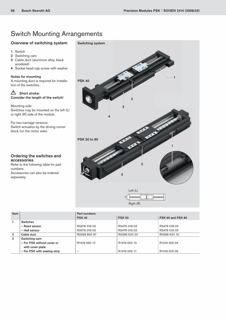
Switch Mounting Arrangements
Ordering the switches and accessoriesRefer to the following table for part numbers.Accessories can also be ordered separately.
Item Part numbersPSK 40 PSK 50 PSK 60 and PSK 90
1 Switches– Reed sensor R3476 018 03 R3476 018 03 R3476 018 03– Hall sensor R3476 019 03 R3476 019 03 R3476 019 03
2 Cable duct R0399 800 97 R0396 620 20 R0396 620 193 Switching cam
– For PSK without cover or with cover plate
R1419 000 12 R1419 000 10 R1419 000 04
– For PSK with sealing strip – R1419 000 11 R1419 000 05
Left (L)
Right (R)
Overview of switching system
SwitchSwitching camCable duct (aluminum alloy, black anodized)Socket head cap screw with washer
Notes for mountingA mounting duct is required for installa-tion of the switches.
Short stroke:Consider the length of the switch!
Mounting side:Switches may be mounted on the left (L) or right (R) side of the module.
For two-carriage versions:Switch actuation by the driving runner block (on the motor side).
123
4
c
Switching system
PSK 50 to 90
PSK 40

57Bosch Rexroth AG
E
G
HI
F
A
B
M
D
C
E
G
H
F
10,5
4,5
17,1
15,3
19,8
Precision Modules PSKR310EN 2414 (2008.03)
Cable duct
FunctionTo accommodate and secure switchesTo house cables
Mounting instructions for PSK 40The cable duct is fastened to the same side as the switches and fi xed to the end blocks of the Precision Module with socket head cap screws and washers (included in delivery).
–
–
Installation dimensions for versions without cover or with cover plate
Installation dimensions for version with sealing strip
– PSK without cover or with cover plate – PSK with sealing strip
Cable duct PSK 40
Cable duct PSK 50 to PSK 90Mounting instructions for PSK 50 to PSK 90The cable duct is mounted to the same side as the switches by snapping it into the T-slots on the frame of the Precision Module and securing it with set screws. The set screws (M) are supplied along with the duct.
Dimensions for cable duct
Dimensions PSK 50 PSK 60 PSK 90A (mm) 21.7 25.2 25.2B (mm) 15.0 15.0 15.0C (mm) 11.5 11.5 11.5D (mm) 16.5 16.5 16.5M (mm) M2.0 M2.5 M2.5
Dimensions PSK 50 PSK 60 PSK 90E (mm) 15.2 15.8 15.4F (mm) 25.8 32.8 45.8G (mm) 19.7 22.6 25.8H (mm) 6.0 6.0 6.0
Dimensions PSK 50 PSK 60 PSK 90E (mm) 15.2 15.8 15.2F (mm) 28.2 35.7 50.2G (mm) 12.2 13.0 13.0H (mm) 12.5 14.0 14.0I (mm) 3.3 1.9 7.4
Arrangement of switching cam and cable duct
Arrangement of switching cam and cable duct
58 Bosch Rexroth AG
35
3
5
6
6.5
Precision Modules PSK R310EN 2414 (2008.03)
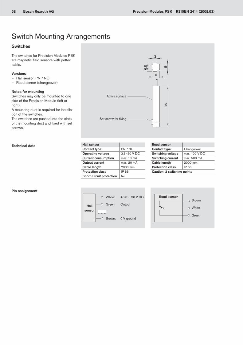
Switch Mounting ArrangementsSwitches
The switches for Precision Modules PSK are magnetic fi eld sensors with potted cable.
VersionsHall sensor, PNP NCReed sensor (changeover)
Notes for mountingSwitches may only be mounted to one side of the Precision Module (left or right).A mounting duct is required for installa-tion of the switches.The switches are pushed into the slots of the mounting duct and fi xed with set screws.
––
Set screw for fi xing
Active surface
Hall sensorContact type PNP NCOperating voltage 3.8–30 V DCCurrent consumption max. 10 mAOutput current max. 20 mACable length 2000 mmProtection class IP 66Short-circuit protection No
Reed sensorContact type ChangeoverSwitching voltage max. 100 V DCSwitching current max. 500 mACable length 2000 mmProtection class IP 66Caution: 2 switching points
Pin assignment
Technical data
White: +3.8 ... 30 V DC
Green: Output
Brown: 0 V ground
Brown
White
Green
Hall sensor
Reed sensor

59Bosch Rexroth AG
ØE
ØD
B2B1
L1
L
6032
ØG
ØF
B3
H3
H2 H
1
45
A
Precision Modules PSKR310EN 2414 (2008.03)
MotorsAC Servo Motors MSK
Motor data
Motor type Dimensions (mm)A B1 B2 B3 ØD ØE ØF ØG H1 H2 H3 L1 L
withoutL
with brake
k6 j6brake
MSK 030C 54 20 2.5 7 9 40 63 4.5 71.5 57.4 42 – 188.0 213.0MSK 040C 82 30 2.5 8 14 50 95 6.6 83.5 69.0 31 42.5 185.5 215.5
Motor type Unit MSK030C-0900 MSK040C-0600Maximum rotary speed nmax (min–1) 9000 6000Maximum permissible torque Mmax (Nm) 4 8.1Rated torque MN (Nm) 0.8 2.7Motor mass moment of inertia Jm (10–6 kgm2) 30 140Mass without brake mm (kg) 2.1 3.6Holding brakeHolding torque Mbr (Nm) 1.0 4.0Brake mass moment of inertia Jbr (10–6 kgm2) 7 23Mass of brake mbr (kg) 0.25 0.32
Dimensions
NotesAll MSK motors have an absolute multi-turn encoder (Hyperface, 128 incre-ments with 4096 revolutions).
The motors can be supplied complete with controller and control unit. For more information on motors, controllers and control systems, see Rexroth catalog “Controllers .... Servo Motors.”
60 Bosch Rexroth AG
ØE
ØD
B2B1 L
B3
H3 H2
ØG
ØF
A H1
45
Precision Modules PSK R310EN 2414 (2008.03)
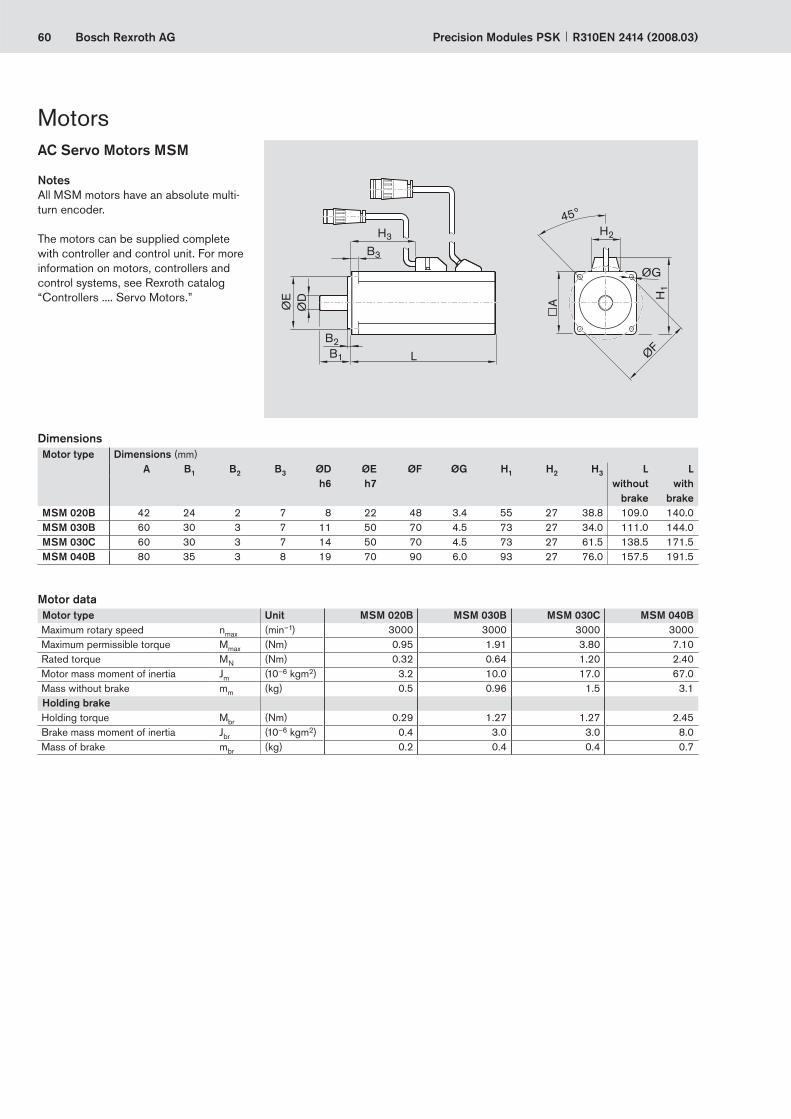
MotorsAC Servo Motors MSM
Motor type Unit MSM 020B MSM 030B MSM 030C MSM 040BMaximum rotary speed nmax (min–1) 3000 3000 3000 3000Maximum permissible torque Mmax (Nm) 0.95 1.91 3.80 7.10Rated torque MN (Nm) 0.32 0.64 1.20 2.40Motor mass moment of inertia Jm (10–6 kgm2) 3.2 10.0 17.0 67.0Mass without brake mm (kg) 0.5 0.96 1.5 3.1Holding brakeHolding torque Mbr (Nm) 0.29 1.27 1.27 2.45Brake mass moment of inertia Jbr (10–6 kgm2) 0.4 3.0 3.0 8.0Mass of brake mbr (kg) 0.2 0.4 0.4 0.7
Motor type Dimensions (mm)A B1 B2 B3 ØD ØE ØF ØG H1 H2 H3 L L
h6 h7 without brake
with brake
MSM 020B 42 24 2 7 8 22 48 3.4 55 27 38.8 109.0 140.0MSM 030B 60 30 3 7 11 50 70 4.5 73 27 34.0 111.0 144.0MSM 030C 60 30 3 7 14 50 70 4.5 73 27 61.5 138.5 171.5MSM 040B 80 35 3 8 19 70 90 6.0 93 27 76.0 157.5 191.5
NotesAll MSM motors have an absolute multi-turn encoder.
The motors can be supplied complete with controller and control unit. For more information on motors, controllers and control systems, see Rexroth catalog “Controllers .... Servo Motors.”
Motor data
Dimensions

61Bosch Rexroth AG
L+0,7 46,5
32,5
22,5
14
Ø83
,5
ØE
ØD
5135
Ø15
–1B1
B2
B3
Ø G
19
25
31
60
ØFA
B1 41± 0,5
Ø51
Ø D
Ø E
5134
Ø15
Ø G
B3
B2
L
3121
14
18 25
21
3131
Ø F
A12
43
VRDM 397 VRDM 3910
VRDM 368
12
43
Precision Modules PSKR310EN 2414 (2008.03)
3-phase Stepping Motors VRDM
NotesAll VRDM motors are equipped with an encoder for rotation monitoring.
The motors can be supplied complete with controller and control unit. For more information on motors, controllers and control systems, see Rexroth catalog “Controllers .... Servo Motors.”
Motor type Unit VRDM 368 VRDM 397 VRDM 3910Maximum permissible torque Mmax (Nm) 1.50 2.00 4.00Motor mass moment of inertia Jm (10–6 kgm2) 38 110 220Motor holding torque Mm (Nm) 1.74 2.26 4.52Mass without brake mm (kg) 1.1 2.5 3.1Step count z (–) 200 / 400 / 500 / 1000 / 2 000 / 4 000 / 5 000 / 10 000Stepping angle per step α (°) 1.8 / 0.9 / 0.72 / 0.36 / 0.18 / 0.09 / 0.072 / 0.036Encoder resolution 1000 increments/revolutionHolding brakeBrake holding torque Mbr (Nm) 1 6 6Brake mass moment of inertia Jbr (10–6 kgm2) 1.6 20 20Mass of brake mbr (kg) 0.5 1.5 1.5
Motor type Dimensions (mm)A B1 B2 B3 ØD ØE ØF ØG L L
without brake
with brake
VRDM 368 57.2 21 1.6 5 8 –0.013 38.1 ±0.025 66.7 5.2 116.0 157.0VRDM 397 85.0 30 2.0 10 12 h6 60.0 h8 99.0 6.5 110.0 156.5VRDM 3910 85.0 30 2.0 10 12 h6 60.0 h8 99.0 6.5 140.0 186.5
Key to illustrationMotor connectorBrakeEncoder connectorBrake connector
1234
Motor data
Dimensions

62 Bosch Rexroth AG
A±0,1
B
E
F
G
D
C
Precision Modules PSK R310EN 2414 (2008.03)
General notes
Do not mount or support the Precision Module by the end blocks! The frame is the main load-bearing part!
Precision Modules can be mounted either with screw-fasteners in the frame itself or with external clamping fi xtures.When mounting Precision Modules, please note the maximum tightening torques listed in the table.
Mounting with screws in the frame
The reference edge on the frame facili-tates alignment of the Precision Module.Suitable for cover options:
Without coverWith cover plate (remove cover plate before mounting the module). For in-stallation dimensions, see the relevant dimension drawings.
Mounting with clamping fi xtures, PSK 50 to PSK 90
The reference edge cannot be used in the region of the clamping fi xtures.Suitable for all cover options.
Clamping fi xturesRecommended number:
3 per 500 mm and side
c
––
–
Mounting
Countersink for M per ISO 4762
Tightening torques for the mounting screws
At friction factor 0.125Strength class 8.8
––
RadiusRmax = 0.3
Reference edge
Mounting with clamping fi xtures, PSK 50 to PSK 90
Mounting with screws in the frame
Precision Module Part numbers Dimensions (mm)Clamping fi xtures A B C D E F G M
PSK 50 R1419 010 02 60 70 12.5 5.0 4.0 8.5 20 M4PSK 60 R1419 010 01 72 85 15.0 6.5 4.8 10.0 22 M5PSK 90 R1419 010 00 100 115 17.5 7.5 5.8 12.0 25 M6
M3 M4 M5 M6
8.8
(Nm)max.
1.3 2.7 5.5 9.5

63Bosch Rexroth AG
øEøD
F
M
C
A
C
A
C
B MMM
1 1
Precision Modules PSKR310EN 2414 (2008.03)
Lube PortsGeneral notes
The lubrication system on Precision Modules has been designed for grease lubricants (grease gun). The lube port supplies lubricant to both the Rail System guideway and the Precision Ball Screw Assembly. If the module has two carriages, both of these must be lubricated.
Lubricant
Without cover
Lube port for customer-built attachment
Customer-built attachment
O-ring
Carriage
Carriage: standard length Carriage: long
Cover plate Sealing strip
Precision Module PSK 40 PSK 50 PSK 60 PSK 90A (mm) 19.0 18.2 16.0 24.6B (mm) – – 22.0 33.3C (mm) 3.0 6.5 9.0 12.0D (mm) 2.5 2.5 2.5 4.0E (mm) 5.0 5.0 5.0 8.0F (mm) 0.6 +0.1 0.6 +0.1 0.7 +0.1 0.5 +0.1M (mm) M2 M2.5 M3 M4
Precision Module
O-ring DIN 3771
Part numbers
PSK 40 to PSK 60
3 x 1 R3411 118 01
PSK 90 5 x 1.5 R3411 108 01
PSK with cover plate or sealing stripOne-point lubrication at either of the two funnel-type lube nipples (1) DIN 3405-D3 per carriage.
For short-stroke applications, please contact us regarding the lubrication arrangements:PSK 40: stroke < 50 mmPSK 50: stroke < 70 mmPSK 60: stroke < 95 mmPSK 90: stroke < 135 mm
PSK 40Lube port for grease gun and for customer-built attachment
PSK 50 to PSK 90Funnel-type lube nipple DIN 3405-D3
PSK 40 PSK 50 to PSK 90
PSK without coverPSK 40: One-point lubrication is possible via the lube port for grease gun on each carriage. Remove the set screw from the lube hole, apply lubricant, then drive the set screw in again.PSK 50 to PSK 90: One-point lubrication at either of the two funnel-type lube nipples DIN 3405-D3 per carriage.One-point lubrication through customer-built attachment: This can be achieved in all PSK types by using the lube port in the carriage. The lube ports are closed with set screws for shipment. Before using the lube ports, the set screws must be removed and O-rings inserted to seal off the customer-built attachment.
–
–
–
Lithium soap grease
PSK 40 PSK 50 to PSK 90
DIN 51825 KP00K KP2KDIN 51818 NLGI 00 NLGI 2Recommended Dynalub 520 Dynalub 510Part numbers R3416 043 00 R3416 037 00
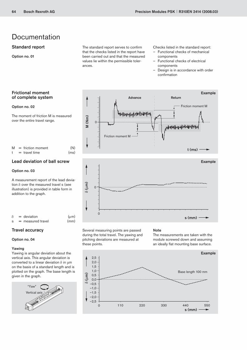
64 Bosch Rexroth AG
M (
Nm
)
0
t (ms)
0
s (mm)0
s (mm)110 220 330 440 5500
–1,0
1,0
–0,5
0,50,0
1,52,02,5
–2,5–2,0–1,5
Precision Modules PSK R310EN 2414 (2008.03)
Friction moment M
Friction moment M
Advance ReturnExample
Checks listed in the standard report:– Functional checks of mechanical
components– Functional checks of electrical
components– Design is in accordance with order
confi rmation
DocumentationThe standard report serves to confi rm that the checks listed in the report have been carried out and that the measured values lie within the permissible toler-ances.
Standard report
Option no. 01
Frictional moment of complete system
Option no. 02
The moment of friction M is measured over the entire travel range.
Several measuring points are passed during the total travel. The yawing and pitching deviations are measured at these points.
NoteThe measurements are taken with the module screwed down and assuming an ideally fl at mounting base surface.
Lead deviation of ball screw
Option no. 03
A measurement report of the lead devia-tion δ over the measured travel s (see illustration) is provided in table form in addition to the graph.
Travel accuracy
Option no. 04
YawingYawing is angular deviation about the vertical axis. This angular deviation is converted to a linear deviation δ in μm on the basis of a standard length and is plotted on the graph. The base length is given in the graph.
Example
Example
Base length 100 mm
“Yaw”
Vertical axis
M = friction moment (N)t = travel time (ms)
δ = deviation (μm)s = measured travel (mm)

65Bosch Rexroth AG
s (mm)110 220 330 440 5500
–1,0
1,0
–0,5
0,5
0,0
1,5
–2,5
–3,0
–3,5
–4,0
–2,0
–1,5
s (mm)
25
–25
–50
–75
–100
0
175 252,5 350 612,5 7000 87,5 437,5 525
Pa
P
Ps/
2P
s/2
U
Precision Modules PSKR310EN 2414 (2008.03)
Base length 100 mm
Example
Positioning accuracy per VDI/DGQ 3441
Option no. 05
Measurement points are selected at irregular intervals along the travel range. This allows even periodical deviations δ in μm to be detected during positioning.Each measurement point is approached several times from both sides.This gives the following parameters.
PitchingPitching means angular deviation about the horizontal axis. This angular deviation is converted to a linear deviation δ in μm on the basis of a standard length and is plotted on the graph. The base length is given in the graph.In addition to graphical representation (see illustrations), a measurement report is supplied in table form.
“Pitch”
Horizontal axis
Positioning accuracy P The positioning accuracy corresponds to the total deviation. It encompasses all the systematic and random deviations during positioning. The positioning
Reversal range U
Example
Position deviation Pa
Position variation range Ps
Documentation
accuracy takes the following characteris-tic values into consideration:– Position deviation– Reversal range– Position variation range
The position deviation corresponds to the maximum difference arising in the mean values of all the measurement points. It describes systematic deviations.
The reversal range corresponds to the difference in mean values of the two approach directions.
The reversal range is determined at every measurement point. It describes systematic deviations.
The position variation range describes the effects of random deviations. It is determined at every measurement point.
δ = deviation (μm)s = measured travel (mm)

66 Bosch Rexroth AG Precision Modules PSK R310EN 2414 (2008.03)

67Bosch Rexroth AGPrecision Modules PSKR310EN 2414 (2008.03)
Rexroth Precision Module PSK
Telephone +49 9721 937-0Telefax +49 9721 937-350 (direct)
Inquiry/Order Form
Single parts:
(Part number): R______ _______ _______
R______ _______ _______
R______ _______ _______
R______ _______ _______
Quantity Order of: ____ pcs, _____ per month, ______ per year, per order, or ________________________________Comments:______________________________________________________________________________________________________________FromCompany: ___________________________________ Name: _______________________________________________
Address: ____________________________________ Department: __________________________________________
_____________________________________________ Telephone: ___________________________________________
_____________________________________________ Telefax: ______________________________________________
Bosch Rexroth AGLinear Motion and Assembly TechnologiesD-97419 SchweinfurtGermany
To be completed by customer: Inquiry / OrderPrecision Module PSK ____________________________
Part number: R_____ ______ ______, length __________mm
Version = Guideway = Drive unit = Carriage = Motor attachment = Motor = Cover = 1st switch = - + mm2nd switch = - ± mm3rd switch = - – mmCable duct = , mmSwitching cam = Documentation =
Ordering data DescriptionPrecision Module PSK 90 Designation Part number: R1465 400 00, 740 mm PSK 90, length = 740 mmVersion = MF01 With motor mount and motor, as shown in diagram MF01Guideway = 18 Rail system, 740 mm longDrive unit = 03 Ball screw 16 x 16Carriage = 24 Two carriages, long, steel version for cover plateMotor attachment = 03 With motor mount for motor MSK 040CMotor = 87 Motor MSK 040C with brakeCover = 01 With cover plate1st switch = 21-L Reed sensor, for mounting at left2nd switch = 22-L Hall sensor, for mounting at left3rd switch = 21-L Reed sensor, for mounting at leftCable duct = 25 Cable duct supplied looseSwitching cam = 30 Switching cam for version without cover or with cover plateDocumentation = 01 Standard report
Ordering example

CanadaBosch Rexroth Canada Corp.3426 Mainway DriveBurlington, Ontario L7M 1A8Tel. +1 905 335-5511Fax +1 905 335-4184
USABosch Rexroth Corporation14001 South Lakes DriveCharlotte, NC 28273Tel. +1 800 REXROTH +1 800 739 7684Fax +1 704 583 0523
AustraliaBosch Rexroth Pty. Ltd.3 Valediction RoadKings Park, NSW 2148, SydneyTel. +61 2 9831 7788Fax +61 2 9831 5553
Great Britain Bosch Rexroth LimitedCromwell RoadSt. Neots, HuntingdonCambs. PE19 2ES Tel. +44 1480 223 298Fax +44 1480 470 789
Bosch Rexroth AGLinear Motion and Assembly TechnologiesErnst-Sachs-Straße 10097424 Schweinfurt, GermanyTel. +49 9721 937-0 Fax +49 9721 937-275www.boschrexroth.com/brl
Your sales partner Subject to technical modifications
SingaporeBosch Rexroth Pte. Ltd.15D Tuas Road638520 SingaporeTel. +65 6861 8733Fax +65 6861 1825
© Bosch Rexroth AG 2008Printed in GermanyR310EN 2414 (2008.03)EN • BRL/MKT2


