Page 1
Portugaliae Electrochimica Acta 2014, 32(3), 213-231
DOI: 10.4152/pea.201403213
PORTUGALIAE
ELECTROCHIMICA
ACTA ISSN 1647-1571
The Effect of Cathode Materials on Indirect Electrochemical
Oxidation of Methyl Orange, Malachite Green
and Methylene Blue
Anantha N.S. Rao, Venkatesha T. Venkatarangaiah*
a Department of P.G. studies and Research in Chemistry, School of Chemical Sciences,
Kuvempu University, Shankaraghatta-577451, Karnataka, India
Received 7 May 2014; accepted 23 June 2014
Abstract
The influence of cathode material on the electrochemical degradation of methyl orange
(MO), methylene blue (MB) and malachite green (MG) dyes was investigated. The
cathode materials used were platinum (Pt), copper (Cu), zinc (Zn) and aluminum (Al).
The electrochemical activity of the selected dyes on the metal cathodes was examined
by cyclic voltammetry (CV). The electrochemical treatment was carried out in both
divided and undivided cells. The degradation process was monitored by UV-Visible
spectroscopy and chemical oxygen demand (COD) measurement. The influence of pH
on discoloration and degradation of dyes was studied. The power consumption and
current efficiency of the treatment process involving different cathode materials was
computed and compared. The role of cathode material in the degradation of dyes has
been established.
Keywords: Malachite green; Methylene blue; Methyl orange; Discoloration;
Degradation.
Introduction
Dyes are the major constituents of textile industrial effluents. They impart
intense color to water. Most of them are highly toxic to aquatic life and also to
human beings. The methylene blue (MB), malachite green (MG) and methyl
orange (MO) dyes are used on large scale in dying industries (Table 1). The MG
is a cationic water soluble dye used in textile industries for coloring nylon, wool,
silk, leather, cotton and jute [1-5]. Also, it finds application as antifungal, anti-
bacterial and anti-parasitical agent in agriculture, fish hatchery and animal
husbandry [1,3,5,6]. In anaerobic conditions, the bacteria commonly present in
* Corresponding author. E-mail address: [email protected]
Page 2
A.N.S Rao & V.T. Venkatarangaiah / Port. Electrochim. Acta 32 (2014) 213-231
214
mammalian intestine convert malachite green into toxic colorless leuco-
malachite green, which poses carcinogenic, mutagenic and teratogenic effects on
aquatic life [1, 4, 7]. The degradation products of malachite green are also
carcinogenic. Intervention of these species into the food chain is lethal. Another
dye, methylene blue, a chlorinated polycyclic synthetic organic compound, has
structural similarity with rhodamine b, naphthol blue black and acid orange 7 [8].
MB is a widely used dye in dying cotton, wool, acrylic and silk [9, 10, 11]. It is
highly stable and antibiodegradable [11]. Its consumption causes nausea,
diarrhea, burning of eyes, vomiting, breathing difficulty, mental disorder,
sweating [9, 10]. Methyl orange represents the azo dye family and is commonly
used in the titrations of mid strength acids. MO has not shown any harmful
effects on rats when used in limited oral and injection range. However, a high
acute oral toxicity was noticed [12].
Table 1. Structure and properties of dyes used in this study.
a wavelength of maximum absorption intensity in water; b CI – color index
Various methods are used to treat the wastewater containing organic dyes.
Physical (precipitation, adsorption) [1, 5, 13-16] chemical [10]; biological [2, 6,
17, 18], photocatalytic [19, 20, 21, 22, 23]; electro-oxidation [4, 9, 24-26];
electro-reduction [27, 28, 29]; photoelectrochemical [30, 31, 32]; electro-Fenton
[33, 34, 35] are amongst the most recognized methods.
The electrochemical oxidation method has attracted a large group of researchers
in the past three decades. In this method, the efficiency of decontamination of
wastewater is dependent on the nature of the electrode. The incineration of
organics into CO2 and H2O is possible only by the oxidation reaction. The
electrochemical oxidation process is therefore widely appreciated and extensive
research on the fabrication of anode material with excellent catalytic activity for
the oxidation of organics (direct oxidation) and generation of oxidants (indirect
oxidation) is underway.
Nevertheless, the cathode material and reaction at cathode also influence the
oxidation of organics. The cathode material can indirectly aid the organic
removal by:
• electro-reduction of dissolved oxygen into H2O2, which is an oxidizing agent;
• direct electro-reduction of organics into compounds susceptible to oxidation;
• generating coagulants for the adsorption of organics;
• direct adsorption of organics (porous carbonaceous cathodes).
Page 3
A.N.S Rao & V.T. Venkatarangaiah / Port. Electrochim. Acta 32 (2014) 213-231
215
The halogenated hydrocarbons like, CHCl3, chlorofluorocarbons (CFCs),
chlorobenzene, chlorophenols, hexachlorocyclohexane are effectively
dehalogenated by electrochemical reduction [33]. The dyes with -SO3-, COO
-, -
SO2NH2, -OH, hydrophilic groups, and azo linkages are susceptible to electro-
reduction [36]. Uniform reduction of organics takes place followed by
adsorption of intermediates on ACF cathode [36-38]. These reactions taking
place in the vicinity of the cathode should be co-operative with the anodic
reactions in order to achieve efficient organic removal. It has been reported that
the degradation of 2-chlorophenol and 2, 4-dichlorophenol using
carbon/polytetrafluoroethylene (C/PTFE) O2-fed as cathode and Ti/IrO2/RuO2 as
anode was cooperative oxidation. The degradation was achieved by direct and
indirect electrochemical oxidation by H2O2 and HO• produced by oxygen
reduction at the cathode [39].
Ag, Al, Au, Cu, Ni, Pb, Pd, Pt, Ti, Zn, graphite, glassy carbon, activated carbon
fiber (ACF) have been used as cathode materials in the electrochemical treatment
of wastewater containing different organic dyes [36-38]. However, only few
research teams have tried to analyze the effect of cathode material on the organic
removal efficiency [40]. Studies on the co-operation between electrochemical
oxidation and reduction reactions in the degradation of aqueous dyes are rarely
found in the literature. Also, the contribution of cathode material to the
degradation of organics has not been studied. In this paper, we investigate the
effect of cathode material and cathodic reactions using different metal cathodes
by evaluating the changes in color and COD of the aqueous synthetic dye
solutions.
Materials and chemicals
Chemicals Commercially available malachite green (MG), methylene blue (MB) and methyl
orange (MO) dyes (S. D. Fine Chemicals Ltd., India) were used for the studies as
received. Millipore water (specific resistance > 18 MΩ at 25 °C, Millipore Elix 3
water purification system, France) was used to prepare the dye solutions and
NaCl was used as supporting electrolyte [analytical grade NaCl (0.2% (w/v), 2 g
L-1
) and 50 mg L-1
dye]. The Zn, Cu, Al metal foils (99.99%) purchased from
Sisco research laboratories, Mumbai, India, and Pt foils supplied by Systronics
India Ltd. Bangalore, India, were used. The dil. HNO3 (10%), dil. HCl (10%) and
NaOH (40%) (HiMedia Laboratories Pvt. Ltd, Bangalore, India) were used for
the pretreatment of electrodes. The dialysis membrane-70 with relative pore size
of 0.1 µm (HIMEDIA) was used in the divided cell experiments.
Experimental The electrolysis experiments were performed under galvanostatic condition and
the current was drawn from a DC power supply (model PS 618
potentiostat/galvanostat 302/2 A supplied by Chem link, Mumbai). All
experiments were carried out at ambient temperature. The electrolysis of dye
solution was carried out in both single compartment and two-compartment cells
Page 4
A.N.S Rao & V.T. Venkatarangaiah / Port. Electrochim. Acta 32 (2014) 213-231
216
under the current density of 40 mA cm-2
to know the contributions of cathodic
and anodic reactions. A volume of 50 cm3 of dye test solution was used in the
undivided cell and in each compartment of the divided cell. Pretreated metal foils
(Al, Cu, Zn and Pt) with exposed surface area of 0.5 cm2 were used as cathode
and Pt (0.54 cm2) as anode in all the experiments. Prior to the experiments, the
Al foil was dipped in 40% NaOH, Cu in 10% HNO3 and Zn in 10% HCl, for 1
min, washed thoroughly with Millipore water, abraded with series of emery
papers of grade number 660 and 1200 followed by washing in Millipore water. Pt
foil was dipped in 10% HNO3 and sonicated for 1 min and thoroughly washed
with Millipore water. The working electrode potential was recorded with respect
to the saturated calomel electrode (SCE). The electrolysis was performed for 60
minutes under stirring using magnetic bar (550 rpm) to achieve proper mixing
and reproducible mass transport onto the electrode surface. The samples were
collected at appropriate time intervals to monitor the color and COD change.
Analysis
Electrochemical measurements The electrochemical behavior of dyes on the cathode surface was evaluated by
CV and the potential for hydrogen evolution on different metal cathodes was
determined by linear sweep voltammetry (LSV) in 0.2% NaCl (w/v) aqueous
solution. The CV measurements were performed at room temperature with a
conventional three electrode system connected to software controlled
electrochemical work station (CH Instruments 660C, USA). The working
electrode was pretreated metal foil (Al, Cu, Pt, Zn). In all the experiments Pt foil
was used as auxillary electrode and SCE was used as reference electrode. CV for
both blank solution [0.2% NaCl (w/v)] and dye solution (50 mg L-1
+ 0.2%
NaCl) were recorded and compared.
Spectroscopic and chemical analysis To follow the degradation process, small aliquots were taken out at regular
intervals, diluted with Millipore water, and UV-Visible absorbance spectrum was
recorded (HR 4000 UV-Vis Spectrophotometer, UV-Vis-NIR light source, DT-
MINI-2-GS, Jaz detector, SP-2102 UVPC (path length=1 cm)). The percentage
color removal with reference to the absorption at λmax was calculated using eq.
(1).
where, Abs0 and Abst are the absorbance at λmax, at time 0 and t minutes of
electrolysis, respectively. The mineralization of dye was monitored by the
changes in COD (gO2 L-1
) as estimated by the open reflux method. The
percentage COD removal was calculated using relation (2).
Page 5
A.N.S Rao & V.T. Venkatarangaiah / Port. Electrochim. Acta 32 (2014) 213-231
217
where, COD0 and CODt are the COD at time 0 and t minutes of electrolysis,
respectively. The percentage average current efficiency (ACE) for the removal of
COD was evaluated by relation (3).
where F is the Faraday’s constant (96,485 C mol-1
), COD in (gO2 L-1
), I is the
current (A), V is the volume (L) of electrolyte, t – time (s), 8 – gram equivalent
mass of oxygen (g equiv-1
). The specific energy consumption per kg COD
removal was calculated by eq. (4).
where I is the average applied current (A), V is the average cell voltage (V), t is
the electrolysis time (h), Vs is the solution volume (L), COD is the decay in
COD (g L-1
).
Results and discussion
Electrochemical studies The LSV was performed on each cathode material in aqueous NaCl 0.2 % (w/v)
solution (Fig. 1) to know the potential for hydrogen evolution reaction (Table 2).
Evidently, Cu exhibited the least activity for hydrogen evolution reaction,
whereas on Pt, hydrogen evolution commenced at -0.7 V. Further, the CV was
recorded for each dye (50 mg L-1
) in 0.2% (w/v) NaCl solution using different
cathode materials as working electrode. The operating potential window was
selected for each cathode and CV scans were performed (Fig. 2).
Both MO and MG were found to be electrochemically inactive on all the cathode
materials within the operating potential window; whereas peaks corresponding to
oxidation and reduction of MB on Cu electrodes were observed in the potential
range of -0.2 to -0.4 V vs. SCE (inset).
A peak at -1.42 V vs. SCE was observed in the CV obtained in blank solution on
Zn electrode. This peak is due to the electro-reduction of Zn2+
ions liberated from
the surface of Zn electrode dipped in NaCl solution. The chemical attack of NaCl
on Zn electrode generates Zn2+
ions. These Zn2+
ions get reduced to Zn at -1.42 V
vs. SCE before hydrogen evolution. To elucidate the presumption of Zn2+
ion
reduction to Zn, the CV scans were performed in 1.0 mM ZnSO4 solution with
0.2 % NaCl as supporting electrolyte under similar conditions. A peak at -1.41 V
vs. SCE (Fig. 3) confirms the Zn2+
reduction. Further, to make sure that this peak
is not due to oxygen reduction, a cyclic voltammogram was recorded on Zn
electrode in aqueous 0.2 % NaCl solution purged with nitrogen for 30 minutes.
The peak at -1.4 V vs. SCE again appeared in CV, negating the chances of O2
reduction reaction. Consequently, the formation of H2O2 by the reduction of O2 is
ruled out in the present case.
Page 6
A.N.S Rao & V.T. Venkatarangaiah / Port. Electrochim. Acta 32 (2014) 213-231
218
Figure 1. Linear sweep voltammogram in 0.2% NaCl aqueous solution for different
metals under the scan rate of 20 mV s-1
.
Figure 2. Cyclic voltammogram in 0.2% NaCl aqueous solution without (blank) and
with dye 50 mg L-1
, scan rate 50 mV s-1
.
Table 2. Hydrogen evolution reaction potential (HER).
Electrode HER / V (vs. SCE)
Copper -1.3
Zinc -1.2
Aluminum -1.1
Platinum -0.7
Page 7
A.N.S Rao & V.T. Venkatarangaiah / Port. Electrochim. Acta 32 (2014) 213-231
219
Figure 3. Cyclic voltammogram in 1.0 mM ZnSO4 aqueous solution with 0.2% NaCl as
supporting electrolyte, scan rate 100 mV s-1
.
Electrolysis in undivided cell Electrolysis of 0.2% (w/v) aqueous NaCl solution containing 50 mg L
-1 dye was
performed for a period of 60 minutes under galvanostatic conditions (40 mA
cm−2
). The progress in degradation was monitored by evaluating the changes in
color (Fig. 4 and 5) and COD (Fig. 6) at regular intervals of time.
Figure 4. The UV-Visible absorption spectra with time of electrolysis using Pt anode
and Al cathode.
Page 8
A.N.S Rao & V.T. Venkatarangaiah / Port. Electrochim. Acta 32 (2014) 213-231
220
Figure 5. The percentage color removal with time of electrolysis on different cathode
materials.
The peaks at 465 nm and 617 nm in the UV-Visible absorption spectrum of MO
and MG slowly disappeared with time on electrolysis and complete discoloration
was achieved for both MO and MG dyes. However, the rate of discoloration of
MO was less as compared to that of MG. 98 % discoloration of MO was
achieved within 35-40 minutes of electrolysis, whereas ~100 % discoloration of
MG was attained within 20 minutes. The absorption in the range of 200-300 nm
in the UV-Visible spectra of MO dye remained as such even after 60 minutes of
electrolysis. This can be ascribed to the aromatic compounds reluctant to
oxidation prevailing in the solution. On the other hand, the MB dye was resistant
to discoloration. The highest % color removal of MB attained after 60 minutes of
electrolysis was only 87 % with Al cathode.
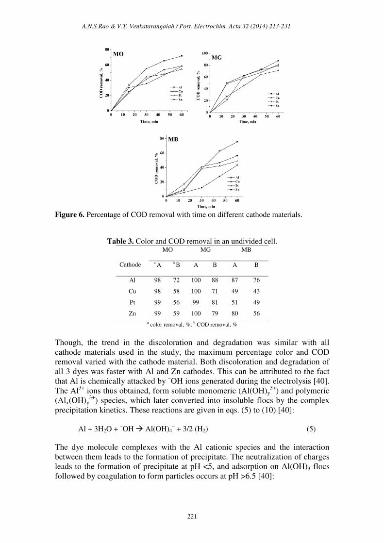
The trend in the COD removal was similar to that of discoloration. The
percentage color and COD removal achieved after a period of 60 minutes
electrolysis has been tabulated in Table 3. The COD removal of MG was faster
and higher as compared to the degradation of MO and MB. The average COD
removal of MB was the least amongst the three dyes with Al cathode. The
percentage COD removal achieved after 60 minutes of electrolysis under similar
conditions followed the order: MG > MO > MB. This suggests that not only the
operating conditions, but also the nature of the organic molecule itself influences
the degradation process. The heterocyclic aromatic structure of MB was most
resistant to degradation and triphenyl methane structure of MG was most
vulnerable to electrochemical oxidation.
Page 9
A.N.S Rao & V.T. Venkatarangaiah / Port. Electrochim. Acta 32 (2014) 213-231
221
Figure 6. Percentage of COD removal with time on different cathode materials.
Table 3. Color and COD removal in an undivided cell.
Cathode
MO MG MB
a A
b B A B A B
Al 98 72 100 88 87 76
Cu 98 58 100 71 49 43
Pt 99 56 99 81 51 49
Zn 99 59 100 79 80 56
a color removal, %; b COD removal, %
Though, the trend in the discoloration and degradation was similar with all
cathode materials used in the study, the maximum percentage color and COD
removal varied with the cathode material. Both discoloration and degradation of
all 3 dyes was faster with Al and Zn cathodes. This can be attributed to the fact
that Al is chemically attacked by –OH ions generated during the electrolysis [40].
The Al3+
ions thus obtained, form soluble monomeric (Al(OH)y3+
) and polymeric
(Alx(OH)y3+
) species, which later converted into insoluble flocs by the complex
precipitation kinetics. These reactions are given in eqs. (5) to (10) [40]:
Al + 3H2O +
–OH Al(OH)4
– + 3/2 (H2) (5)
The dye molecule complexes with the Al cationic species and the interaction
between them leads to the formation of precipitate. The neutralization of charges
leads to the formation of precipitate at pH <5, and adsorption on Al(OH)3 flocs
followed by coagulation to form particles occurs at pH >6.5 [40]:
Page 10
A.N.S Rao & V.T. Venkatarangaiah / Port. Electrochim. Acta 32 (2014) 213-231
222
Dye-H + (HO)OAl(s) Dye-OAl(s) + H2O (6)
Dye + monomeric Al [Dye-monomeric Al](s) pH < 5.0 (7)
Dye + polymeric Al [Dye-polymeric Al](s) pH < 5.0 - 6.0 (8)
Dye + Al(OH)3(s) [Particle] pH > 6.5 (9)
[Dye-polymeric Al](s) + Al(OH)3(s) [Particle] (10)
The large surface area of Al(OH)3(s) flocs adsorbs soluble organic compounds
[36, 40]. On electrolysis for 60 minutes, the pH of the solution was > 7.8 for all
dyes. Under these conditions the reactions in eqs. 9 and 10 are favorable. As a
result, the formation of froth and particulates is expected and the same was
observed during the electrolysis. Also, the hydrogen evolution and dissolution of
cathode material were noticed. The dissolution of Zn metal into Zn2+
ions in
NaCl solution is evident by the CV studies, and very low concentration of Zn2+
ions in the test solution is expected.
It is known that at low zinc concentrations, the Zn2+
ion dominates up to pH 8.7,
while Zn(OH)2 is the dominant species between pH 8.7 and 11.4. This Zn(OH)2
acts as adsorbent for the adsorption of dye molecules. The following reactions
are expected.
Zn + H2O +
-OH Zn(OH)2(s) + ½ H2 (11)
Dye + Zn(OH)2(s) [Particle] (12)
It was established that during electrolysis of aqueous solutions using NaCl, HOCl
predominates in the pH range 3-8, and in pH > 8, -OCl is the dominant species
(Eq. 13-16) [41, 42]. HOCl with higher standard reduction potential is a strong
oxidizing agent [40, 43]. In the present case, the pH of dye solution lies in the
range where both electro-flocculation and formation of oxidizing agents are
favored. The combined effect of oxidation brought about by the active chlorine
species HOCl, Cl2, -OCl and the electro-floccuation, resulted in higher COD
removal with Al and Zn cathodes.
2Cl
- → Cl2(aq) + 2e
- (Standard potential of Cl2 (E
o) = 1.40 V vs. SHE) (13)
Cl2(aq) + H2O → HOCl + H+ + Cl
- (E
o of HOCl = 1.49 V vs. SHE) (14)
HOCl ↔ H+ + OCl
- (pH 3-8 ↔ pH > 8) (E
o of ClO
- = 0.89 V vs. SHE) (15)
Dye + OCl- → Intermediates → CO2 + H2O + Cl
- (16)
Degradation in a divided cell To determine the effect of cathode material and cathodic reactions on the
degradation of dyes by indirect electro-oxidation process, experiments were
conducted in a divided cell.
Page 11
A.N.S Rao & V.T. Venkatarangaiah / Port. Electrochim. Acta 32 (2014) 213-231
223
The progress in color and COD removal (Fig. 7 – 9) in the anode compartment
was monitored and these data are summarized in Table 4. Complete discoloration
of both MO and MG was achieved in the anode compartment of the divided cell.
For MB, the discoloration was above 90% with all cathodes. The % COD
removal was in the order MG > MO > MB. Small % color and COD removal was
noticed in the cathode compartment. The color removal observed for MB
solution in the cathode compartment was approximately 15% and there was no
considerable change in its COD with all 4 cathode materials (< 10%). For MO,
the color and COD removal achieved in the cathode compartment was
approximately 12% and 8% respectively, irrespective of the cathode material.
The % COD removal realized for MG was between 20 and 25 %. These changes
in color and COD removal in the cathode compartment of the divided cell can be
attributed to the adsorption and / or direct electro-reduction of dyes on the
electrode surface.
The changes in the UV-Visible spectrum of MB dye during the electrolysis were
similar in both undivided and anode compartment of divided cell. However for
MO and MG, the UV-Visible absorption spectra exhibited significant differences
in divided and undivided cell systems. Three characteristic peaks in the UV-
Visible spectrum of MG gradually diminished on electrolysis in the undivided
cell, whereas for the solution in the anode compartment of divided cell a new
peak around 469 nm was observed. The green solution of MG dye turned yellow
after 15 minutes of electrolysis and became colorless at 60 minutes of
electrolysis. The MO dye showed a peak at 465 nm for both solutions of
undivided and anode compartment of divided cell. During electrolysis, the
solution of anode compartment of divided cell exhibited red shift to 500 nm at
the beginning of electrolysis and its intensity decreased to zero by the end of the
experiment. In the undivided cell, no such shift was noticed but the intensity of
the peak gradually reduced to zero at 465 nm.
One of the important observations made is that the pH of the test solution of
electrolysis changes during the passage of time in all experiments. In the case of
the undivided cell, the pH of the test solution increased on electrolysis
irrespective of the dye solution. However, in the divided cell there was rise in pH
in the cathode compartment and fall in pH of anode compartment. The pH
changes observed on electrolysis in the divided and undivided cell systems have
been given in Table 5.
As mentioned earlier, the acidic condition encourages the subsistence of in-situ
generated HOCl which oxidized the dyes, resulting in the color and COD
removal. As a result, the percentage of discoloration and degradation achieved in
the anode compartment was higher than that observed in the undivided cell.
Page 12
A.N.S Rao & V.T. Venkatarangaiah / Port. Electrochim. Acta 32 (2014) 213-231
224
Figure 7. Percentage of color removal in the anode compartment of the divided cell.
Figure 8. Percentage of color removal in the anode compartment of the divided cell
system.
Figure 9. UV-Visible absorption spectrum of MG and MO dyes in the anode
compartment of the divided cell.
Page 13
A.N.S Rao & V.T. Venkatarangaiah / Port. Electrochim. Acta 32 (2014) 213-231
225
Table 4: Color and COD removal in a divided cell.
Cathode
MO MG MB
a A
b B A B A B
Al 100 51 100 61 92 48
Cu 99 51 99 63 98 47
Pt 99 58 100 60 99 54
Zn 100 60 100 58 92 53
a color removal, %; b COD removal, %; in the anode compartment after 60 minutes electrolysis
The color of MO and MG dyes are pH sensitive. The MO dye is yellow above
pH 4.4 and turns red in pH <4.4. The pH of as prepared MO solution was 6.2,
which increased to 11.8 in the cathode compartment on electrolysis for 60
minutes. In the anode compartment, the MO solution turned red due to reduction
in pH which is < 4.4 after electrolysis. The red shift in the UV-Visible absorption
at 465 nm is due to this pH change. The discoloration of red solution of MO dye
in anode solution was brought about by the in-situ generated active chlorine
species. However, the MO dye solution in the cathode compartment did not show
any change in the absorption intensity. This is because the pH of cathode
compartment turned basic on electrolysis. The MO dye solution is yellow in
basic pH and persisted throughout the experiment.
Table 5. pH of dye solutions before and after electrolysis.
Divided cell
Undivided cell Anode compartment Cathode compartment
Dye Initial Final Final Final
MO 6.2 8.4 2.2 11.8
MG 4.0 7.9 2.1 12.1
MB 5.2 9.0 2.2 11.6
In case of MG, at the end of the experiment, the solution pH of the anode and the
cathode compartment were 2.2 and 12.1, respectively. It was noticed that the pH
of MG dye solution when varied, imparts green color to the solution in the pH
range 1.8 to 11.4. Below pH 1.8 the color of MG dye solution was yellow and
this color remains but in pH above 11.8 it is colorless. After the electrolysis, the
anode compartment solution pH was 2.2. Therefore, the yellow color of MG was
not due to the pH change but due to the intermediate compounds generated by
the indirect electro-oxidation of MG. The peak at 256 nm corresponding to the
aromatic structure, regularly diminished and reached a minimum. The color
removal was due to the oxidative degradation brought about by the active
chlorine species. On the contrary, the intense green color of MG solution in the
cathode compartment slowly faded and became colorless on electrolysis with
time.
Page 14
A.N.S Rao & V.T. Venkatarangaiah / Port. Electrochim. Acta 32 (2014) 213-231
226
Figure 10. UV-Visible absorption spectrum of MG dye in the cathode compartment of
the divided cell.
This change in color was due to pH change occurred in cathode compartment.
The conjugation in the MG structure is lost due to the formation of
triphenylcarbinol structure by basic hydrolysis of MG (eq. 17) [40, 44, 45]. The
absorbance observed in the UV-Visible spectrum at 256 nm of the cathode
compartment can be attributed to this structure, which persisted even after
electrolysis for 60 min (Fig. 10).
(17)
The COD removal for a particular dye solution in the anode compartment of the
divided cell was almost the same irrespective of the cathode material used. This
is because the degradation was brought about only by the in-situ generated active
chlorine species and the concentration of the active chlorine species generated for
a particular current density was the same. From the COD removal data given in
Tables 3 and 5, the overall degradation achieved in the undivided cell system and
in the anode compartment of the divided cell system is comparable.
Energy consumption and efficiency The specific energy consumption and the average current efficiency for
maximum COD removal in 60 minutes of electrolysis was calculated for both
undivided and divided systems and presented in Table 6.
In general, the performance of Al-Pt and Zn-Pt (cathode – anode) pairs was
found to be the highest as compared to Cu-Pt and Pt-Pt pairs. As evident from the
data, the electrolytic system with Al and Zn cathodes showed the highest
efficiency of COD removal with low energy consumption.
Page 15
A.N.S Rao & V.T. Venkatarangaiah / Port. Electrochim. Acta 32 (2014) 213-231
227
Table 6. Specific energy consumption and average current efficiency (ACE) for COD
removal using the undivided cell.
Cathode
MO MG MB
aA
bB A B A B
Al 30 274 27 313 38 216
Cu 25 367 23 402 31 433
Pt 24 400 24 391 24 389
Zn 25 3845 26 338 29 306
a ACE, %; b specific energy consumed in kWh (kgCOD)-1
The performance of electrolytic cell system with Cu and Pt cathodes was just
satisfactory. The MG dye consumed the highest specific energy for the
degradation. Although the MG dye color removal was faster than the other two
dyes, the degradation of the dye consumed more energy. This can be ascribed to
the resistance offered by the intermediates generated by the oxidation of MG.
The energy required to reduce the COD to a particular level in the degradation of
MG dye was more than that required to reduce the COD to the same level in case
of MO and MB.
Conclusion
The degradation of MG, MO and MB was conducted in undivided and divided
cell systems with different cathode materials. The in-situ generated active
chlorine species brought about the degradation of organics. The performance of
Al and Zn metals as cathode materials was found to be higher than that of Cu and
Pt as cathodes in this process. The changes in the pH of the wastewater matrix
influenced the color and COD removal in divided and undivided cell systems.
The basic pH attained on electrolysis and aqueous chloride solution chemically
attacked the Al and Zn cathodes, which led to the formation of flocs. This
resulted in the higher percentage color and COD removal with Al and Zn
cathodes in the undivided cell system. The decoloration and degradation in the
anode compartment of the divided cell was comparable with the undivided cell;
however, the COD removal achieved for each dye was almost the same with all
the cathode materials. The higher acidic pH in the divided cell led to the faster
color and COD removal in the anode compartment of the divided cell. The pH
variation in the undivided cell was just satisfactory to sustain highly reactive
active chlorine species and the formation of flocs, which led to higher color and
COD removal with Al and Zn cathodes, whereas Cu and Pt resistant to chemical
reaction with –OH and chloride media produced no flocs and hence the showed
reduced performance, as is evident from the calculated current efficiency and
energy consumption data. Complete discoloration of MG and MO was
successfully achieved in all cases. The MB dye showed highest resistance to both
decoloration and degradation. This indicates that not only the operating
Page 16
A.N.S Rao & V.T. Venkatarangaiah / Port. Electrochim. Acta 32 (2014) 213-231
228
conditions but the cathode material and also the property of dye itself affect the
color and COD removal of wastewater containing these dyes.
Acknowledgements
Authors thank the University Grants Commission, New Delhi (Ref: F. No. 41-231/2012
(SR) Dated 16/07/2012) Govt. of India for providing financial assistance to carry out
this work, and Department of chemistry, Kuvempu University for providing laboratory
facilities.
References 1. Cheng W, Wang SG, Lua L, et al. Removal of malachite green (MG) from
aqueous solutions by native and heat-treated anaerobic granular sludge.
Biochem Eng Jour. 2008;39:538–546.
2. Kalyani DC, Telke AA, Surwase SN, et al. Effectual decolorization and
detoxification of triphenylmethane dye malachite green (MG) by
Pseudomonas aeruginosa NCIM 2074 and its enzyme system. Clean Techn
Environ Policy. 2012;14:989–1001.
3. Murugesan K, Yang IH, Kim YM, et al. Enhanced transformation of
malachite green by laccase of ganoderma lucidum in the presence of natural
phenolic compounds. Appl Microbiol Biotechnol. 2009;82:341–350.
4. Soloman PA, Basha CA, Velan M, et al. Electro oxidation of malachite
green and modeling using ANN. Chem Biochem Eng Q. 2010;24:445–452.
5. Soni A, Tiwari A, Bajpai AK. Removal of malachite green from aqueous
solution using nano-iron oxide-loaded alginate microspheres: batch and
column studies. Res Chem Intermed. 2014;40:913-930.
6. Daneshvar N, Ayazloo M, Khataee AR, et al. Biological decolorization of
dye solution containing malachite green by microalgae cosmarium sp.
Biores Technol. 2007;98:1176–1182.
7. Henderson AL, Schmitt TC, Heinze TM, et al. Reduction of malachite
green to leucomalachite green by intestinal bacteria. App Environ Microbio.
1997;63:4099–4101.
8. Hernández-Torres ME, Ojeda-Carrera MT, Sánchez-Cantú M, et al.
CdS/TiO2 composite films for methylene blue photodecomposition under
visible light irradiation and non-photocorrosion of cadmium sulfide.
Chemical Papers. 2014;68:1257-1264.
9. El Hajj Hassan MA, El Jamal MM. Kinetic study of the electrochemical
oxidation of methylene blue with Pt electrode. Port Electrochim Acta.
2012;30:351-35.
10. Han TH, Khan MM, Kalathil S, et al. Simultaneous enhancement of
methylene blue degradation and power generation in a microbial fuel cell
by gold nanoparticles. Ind Eng Chem Res. 2013;52:8174−8181.
11. Wang Q, Tian S, Ning P. Degradation mechanism of methylene blue in a
heterogeneous Fenton-like reaction Catalyzed by Ferrocene. Ind Eng Chem
Res. 2014;53:643-649.
Page 17
A.N.S Rao & V.T. Venkatarangaiah / Port. Electrochim. Acta 32 (2014) 213-231
229
12. Toxicity profile for methyl orange, Bibra toxicology advice and consulting
(1992), http://www.bibra-information.co.uk/profile-55.html. Accessed Jan
2014.
13. El-Sharkawy EA, Soliman AY, Al-Amer KM. Comparative study for the
removal of methylene blue via adsorption and photocatalytic degradation. J
Colloid Interf Sci. 2007;310:498–508.
14. Rajeshkannan R, Rajamohan, Rajasimman M. Removal of malachite green
from aqueous solution by sorption on hydrilla verticillata biomass using
response surface methodology. Front Chem Eng China. 2009;3:146–154.
15. Ru J, Hua-yue Z, Guang-ming Z, et al. Synergy of adsorption and visible
light photocatalysis to decolor methyl orange by activated carbon/nanosized
CdS/chitosan composite. J Cent South Univ Technol. 2010;17:1223−1229
16. Vecitis CD, Gao G, Liu H. Electrochemical Carbon Nanotube Filter for
Adsorption, Desorption, and Oxidation of Aqueous Dyes and Anions. J
Phys Chem C. 2011;115:3621–3629.
17. Deng D, Guo J, Zeng G, et al. Decolorization of anthraquinone,
triphenylmethane and azo dyes by a new isolated Bacillus cereus strain
DC1. Int Biodeter Biodegrad. 2008;62:263–269.
18. Noraini CHC, Morad N, Norli I, et al. Methylene blue degradation by
sphingomonas paucimobilis under aerobic conditions. Water Air Soil
Pollut. 2012;223:5131–5142.
19. Ameen S, Akhtar MS, Kim YS, et al. Synthesis and characterization of
novel poly(1-naphthylamine)/zinc oxide nanocomposites: Application in
catalytic degradation of methylene blue dye. Colloid Polym Sci.
2010;288:1633–1638.
20. Juan Y, Jun D, Cai ZJ, et al. Mechanism of photocatalytic degradation of
dye MG by TiO2-film electrode with cathodic bias potential. Chin Sci Bull,
Phys Chem. 2010;55:131–139.
21. Lei J, Li X, Li W, et al. Photocatalytic degradation of methyl orange on
arrayed porous iron-doped anatase TiO2. J Solid State Electrochem.
2012;16:625–632.
22. Shen J, Wu YN, Fu L, et al. Preparation of doped TiO2 nanofiber
membranes through electrospinning and their application for photocatalytic
degradation of malachite green. J Mater Sci. 2014;49:2303-2314.
23. Xu S, Zhu Y, Jiang L, et al. Visible Light Induced Photocatalytic
Degradation of Methyl Orange by Polythiophene/TiO2 Composite Particles.
Water Air Soil Pollut. 2010;213:151–159.
24. da Silva MR, Antonia LHD, Scalvi LVA, et al. Deposition and
characterization of BiVO4 thin films and evaluation as photoanodes for
methylene blue degradation. J Solid State Electrochem. 2012;16:3267–
3274.
25. Panizza M, Barbucci A, Ricotti R, et al. Electrochemical degradation of
methylene blue. Sep Purif Technol. 2007;54:382–387.
26. Singh S, Srivastava VC, Mall ID. Mechanism of Dye Degradation during
Electrochemical Treatment. J Phys Chem C. 2010;117:15229−15240.
Page 18
A.N.S Rao & V.T. Venkatarangaiah / Port. Electrochim. Acta 32 (2014) 213-231
230
27. Fourcade F, Delawarde M, Guihard L, et al. Electrochemical Reduction
Prior to Electro-Fenton Oxidation of Azo Dyes: Impact of the Pretreatment
on Biodegradability. Water Air Soil Pollut. 2013;224:1385.
28. Liu RH, Sheng GP, Sun M, et al. Enhanced reductive degradation of methyl
orange in a microbial fuel cell through cathode modification with redox
mediators. Appl Microbiol Biotechnol. 2011;89:201–208.
29. Yahiaoui I, Aissani-Benissad F, Madi K, et al. Electrochemical Pre-
Treatment Combined with Biological Treatment for the Degradation of
Methylene Blue Dye: Pb/PbO2 Electrode and Modeling-Optimization
through Central Composite Design. Ind Eng Chem Res.
2013;52:14743−14751.
30. Valatka E, Kulėšius. TiO2-mediated photoelectrochemical decoloration of
methylene blue in the presence of peroxidisulfate. J App Electrochem.
2007;37:415–420.
31. Zhao Q, Li X, Wang N, et al. Facile fabrication, characterization, and
enhanced photoelectrocatalytic degradation performance of highly oriented
TiO2 nanotube arrays. J Nanopart Res. 2009;11:2153–2162.
32. Zhou Z, Zhu L, Li J, et al. Electrochemical preparation of TiO2/SiO2
composite film and its high activity toward the photoelectrocatalytic
degradation of methyl orange. J Appl Electrochem. 2009;39:1745–1753.
33. Brillas E, Cabot P, Casado J. Electrochemical Methods for Degradation of
Organic Pollutants in Aqueous Media. In: Matthew AT (ed). Chemical
degradation methods for wastes and pollutants, Environmental and
industrial applications. New York, USA;2013. pp 210-273.
34. Minero C, Lucchiari M, Evione D, et al. Fe(III)-enhanced sonochemical
degradation of methylene blue in aqueous solution. Environ Sci Technol.
2005;39:8936-8942.
35. Yang S, He H, Wu D, et al. Degradation of methylene blue by
heterogeneous Fenton reaction using titanomagnetite at neutral pH values:
process and affecting factors. Ind Eng Chem Res. 2009;48:9915–9921.
36. Zhemin S, Wenhua W, Jinping J, et al. Degradation of dye solution by an
activated carbon fiber electrode electrolysis system. J Hazar Mater B.
2001;84:107–116.
37. Li F, Yanwei Z, Weishen Y, et al. Electrochemical degradation of amaranth
aqueous solution on ACF. J Hazar Mater B. 2006;137:1182–1188.
38. Li F, Yanwei Z, Weishen Y, et al. Electrochemical degradation of aqueous
solution of Amaranth azo dye on ACF under potentiostatic model. Dyes and
Pigments. 2008;76:440-446.
39. Wang H, Wang JL. The cooperative electrochemical oxidation of
chlorophenols in anode-cathode compartments. J Hazar Mater 154 (2008)
44-50.
40. Martínez-Huitle CA, Brillas E. Decontamination of wastewaters containing
synthetic organic dyes by electrochemical methods: a general review. Appl
Catal B Environ. 2009;87:105–145.
Page 19
A.N.S Rao & V.T. Venkatarangaiah / Port. Electrochim. Acta 32 (2014) 213-231
231
41. Fornazari ALT, Malpass GRP, Miwa DW, et al. Application of
Electrochemical Degradation of Wastewater Composed of Mixtures of
Phenol–Formaldehyde. Water, Air, Soil Pollut. 2012;223:4895-4904.
42. Malpass GRP., Miwa DW, Santos RL, et al. Unexpected toxicity decrease
during photoelectrochemical degradation of atrazine with NaCl. Environ
Chem Lett. 2012;10:177–182.
43. Song S, Fan J, He Z, et al. Electrochemical degradation of azo dye C.I.
Reactive Red 195 by anodic oxidation on Ti/SnO2–Sb/PbO2 electrodes.
Electrochim Acta. 2010;55:3606–3613.
44. Samiey B, Toosi AR. Kinetics study of malachite green fading in the
presence of TX-100, DTAB and SDS. Bull Korean Chem Soc. 2009;30:
2051.
45. Soriyan O, Owoyomi O, Ogunniyi A. The Basic Hydrolysis of Malachite
Green in β-Cyclodextrin/Cetyltrimethlammonium Bromide (CTAB) Mixed
System. Acta Chim Slov. 2008;55:613–616.


![Applied electrochemical biosensor based on covalently self ... · PDF fileAuto lab Potentiostat/Galvanostat, ... tremely corrosive and must be handled carefully]) ... Electrochemical](https://static.documents.pub/doc/80x56/5abe0b0e7f8b9a5d718c7cf7/applied-electrochemical-biosensor-based-on-covalently-self-lab-potentiostatgalvanostat.jpg)


