Proceedings of the 4 th International Conference on Civil Engineering for Sustainable Development (ICCESD 2018), 9~11 February 2018, KUET, Khulna, Bangladesh (ISBN-978-984-34-3502-6) ICCESD-2018-4707-1 THE EFFECT OF EMBEDMENT DEPTH ON BEARING CAPACITY OF STRIP FOOTING IN COHESIVE FRICTIONAL MEDIUM Hasinur Rahman Nur 1 , Md. Shafiqul Islam 2 and Md. Rokonuzzaman 3 1 Undergraduate Student, Dept. of Civil Engineering, Khulna University of Engineering and Technology, Bangladesh, e-mail: [email protected]2 Assistant Professor, Dept. of Civil Engineering, Khulna University of Engineering and Technology, Bangladesh, e-mail: [email protected]3 Professor, Dept. of Civil Engineering, Khulna University of Engineering and Technology, Bangladesh, e-mail: [email protected]ABSTRACT In this study, two-dimensional finite-element models incorporating a Mohr-Coulomb elasto-plastic material model were validated for the evaluation of the bearing capacity factors for rough strip footings under vertical loading in c- soil. Earlier proposals are based on empirical data for surface condition in non-frictional medium, whereas a new suggestion for these factors presented in this paper is based on the elasto-plastic model of the soil in cohesive frictional medium considering variable friction angle and embedment depth. All the finite element analyses of this study were carried out using the finite element system ABAQUS. Finally, an attempt is made to propose a more accurate solution to estimate the bearing capacity factors of rough strip footing with equations fitted by simple functions of the soil friction angle and footing embedment depth. Keywords: Foundation, Bearing capacity, Strip footing, Finite element analyses (FEM). 1. INTRODUCTION The bearing capacity of foundations has become a fundamental problem in geotechnical engineering. For all structures placed on a soil foundation, geotechnical engineers must ensure that the soil has sufficient load carrying capacity so that the foundation does not collapse or become unstable under any conceivable loading (Zhu & Michalowski, 2005). A lot of research have been done which proposed approximate techniques for the estimation of bearing capacity of foundation and generally the conventional bearing capacity theory used which is suitable for strip footing but no exact solution has been established. (Terzaghi, 1943) proposed the following formula to calculate the ultimate bearing pressure of soil beneath a strip footing, where the influence of soil cohesion (c), surcharge (q) and the weight of soil (g) are considered independently: Qult = cNc + qNq + BNγ (1) Where, Qult= ultimate pressure; B= footing width; D= depth of embedment; γ= unit weight of the soil; c= soil cohesion; Nc, Nq and Nγ= bearing capacity factors dependent only on the angle of the internal friction of soil. Terzaghi calculated all three components in Eq. (1) based on limit equilibrium. Also, (Terzaghi, 1943), (Reissner, 1924), and (Chen, 1975) among others, calculated the bearing capacity factors as follows: Nq = Kp * exp(п tan ) Nc = ( Nq – 1 ) cot (2) and, Kp ; Where, =internal friction angle. There are several suggestions in different literature for factor Nγ (Meyerhof, 1963);(Hansen, 1970);(Vesic, 1973). A newer proposal was derived based on the strict upper bound approach of limit analysis (Michalowski, 1997). Nγ = tan (3)
Transcript
Proceedings of the 4th International Conference on Civil Engineering for Sustainable Development (ICCESD 2018), 9~11 February 2018, KUET, Khulna, Bangladesh (ISBN-978-984-34-3502-6)
ICCESD-2018-4707-1
THE EFFECT OF EMBEDMENT DEPTH ON BEARING CAPACITY OF STRIP FOOTING IN COHESIVE FRICTIONAL MEDIUM
Hasinur Rahman Nur1, Md. Shafiqul Islam2 and Md. Rokonuzzaman3
1 Undergraduate Student, Dept. of Civil Engineering, Khulna University of Engineering and Technology, Bangladesh, e-mail: [email protected]
2 Assistant Professor, Dept. of Civil Engineering, Khulna University of Engineering and Technology, Bangladesh, e-mail: [email protected]
3 Professor, Dept. of Civil Engineering, Khulna University of Engineering and Technology, Bangladesh, e-mail: [email protected]
ABSTRACT
In this study, two-dimensional finite-element models incorporating a Mohr-Coulomb elasto-plastic material model were validated for the evaluation of the bearing capacity factors for rough strip footings under vertical loading in c- soil. Earlier proposals are based on empirical data for surface condition in
non-frictional medium, whereas a new suggestion for these factors presented in this paper is based on the elasto-plastic model of the soil in cohesive frictional medium considering variable friction angle and embedment depth. All the finite element analyses of this study were carried out using the finite element system ABAQUS. Finally, an attempt is made to propose a more accurate solution to estimate the bearing capacity factors of rough strip footing with equations fitted by simple functions of the soil friction angle and footing embedment depth.
Keywords: Foundation, Bearing capacity, Strip footing, Finite element analyses (FEM).
1. INTRODUCTION
The bearing capacity of foundations has become a fundamental problem in geotechnical engineering. For all structures placed on a soil foundation, geotechnical engineers must ensure that the soil has sufficient load carrying capacity so that the foundation does not collapse or become unstable under any conceivable loading (Zhu & Michalowski, 2005). A lot of research have been done which proposed approximate techniques for the estimation of bearing capacity of foundation and generally the conventional bearing capacity theory used which is suitable for strip footing but no exact solution has been established. (Terzaghi, 1943) proposed the following formula to calculate the ultimate bearing pressure of soil beneath a strip footing, where the influence of soil cohesion (c), surcharge (q) and the weight of soil (g) are considered independently:
Qult = cNc + qNq + BNγ (1)
Where, Qult= ultimate pressure; B= footing width; D= depth of embedment; γ= unit weight of the soil; c= soil cohesion; Nc, Nq and Nγ= bearing capacity factors dependent only on the angle of the internal friction of soil. Terzaghi calculated all three components in Eq. (1) based on limit equilibrium. Also, (Terzaghi, 1943), (Reissner, 1924), and (Chen, 1975) among others, calculated the bearing capacity factors as follows: Nq = Kp * exp(п tan )
Nc = ( Nq – 1 ) cot (2)
and, Kp ; Where, =internal friction angle.
There are several suggestions in different literature for factor Nγ (Meyerhof, 1963);(Hansen, 1970);(Vesic, 1973). A newer proposal was derived based on the strict upper bound approach of limit analysis (Michalowski, 1997).
Nγ = tan (3)
4th International Conference on Civil Engineering for Sustainable Development (ICCESD 2018)
ICCESD-2018-4707-2
The factor in Eq.(3) is a closed-form approximation from the numerical results for the analysis of Coefficient Nγ for Rough and Smooth Strip Footings (Michalowski, 1997). In recent years, both theoretical and experimental investigation of the ultimate bearing capacity of square and circular footings received the attention of many researchers. For example, (Cerato & Lutenegger, 2007) experimentally investigated the bearing capacity factor Nγ on sand for both square and circular footings. He found that the square footing provides higher bearing capacity than the circular footing. Similar results were found for the footing resting on sand by (Lavasan, A. A., & Ghazavi, 2012) and (Kiran, M., & Bacha, 2015). These investigations are significant for footings placed on sand, but they do not provide any information in the case of footings resting on frictional-cohesive (c- ) soil. Only
few numerical studies (Zhu & Michalowski, 2005); (Kumar & & Khatri, 2011) were performed on (c- ) soil. This study involved numerical investigation of the ultimate bearing capacity with
finite element analysis of (c- ) soil for rough strip footings subjected to vertical loading and
compared with previous studies through graphical presentation.
2. METHODOLOGY
ABAQUS is a software application used for both the modelling and analysis of mechanical components and assemblies (pre-processing). It is most suitable for analyzing the nonlinear behavior of material, failure phenomena and visualizing the finite element analysis result. All the finite element analyses of this study were carried out using the software ABAQUS. Two dimensional model was developed for strip footing analysis for different frictional angles and embedment depth. Simple soil conditions were modelled representing an isotropic linear elastic-perfectly plastic material considering embedment depth H/B= 0, 0.1, 0.3, 0.5, 0.75, 1.0, 1.5, 2.0 and frictional angle from zero degree to 40 degree. Meshing and displacement were applied to the model and ABAQUS was used to arrive at the limit loads (bearing capacity) of rough strip footings.
2.1 Element Size Study
On surface footing element size analysis was carried out to fix the element size and meshing as well as displacement. The fixation of mesh element size is an important part of modelling because it determines the amount of element number and time required for the analysis of the model. After fixation of the element size, the type of element was also selected whether it is linear, quadratic or triangular. The quadratic element shows more accurate result and load-displacement curve become constant very quickly. Although triangular element shows more accurate result compared to quadratic but to avoid huge time for the analysis quadratic element were used.
2.2 Modelling
Finite element system ABAQUS was used to arrive at the limit loads (bearing capacity) of rough strip footings and different meshing and displacement applied for two dimensional modelling. The model is created in four steps. In the first step which is the initial condition, all boundary conditions are defined as described previously. In the second step, surcharge load is applied on top of the model and gravity load is applied to the whole model. In the third step, a downward movement is applied on top of the soil under footing area where δ is vertical displacement and B is the width of footing. It should be noted that the duration for this l step is 100 seconds to avoid sudden collapse of soil body. Moreover, it is assumed that relative movement between soil and footing is impossible. The boundary conditions ensures no lateral movement will occur. For rough footing lateral displacement are restrained to zero and only vertical displacement occurred.
4th International Conference on Civil Engineering for Sustainable Development (ICCESD 2018)
ICCESD-2018-4707-3
2.2.1 Materials
Simple soil conditions were modelled representing an isotropic linear elastic-perfectly plastic
material with uniform undrained shear strength and depth, . A fine grained material
subjected to a period of loading sufficiently short such that no drainage will take place. Poisson’s ratio ν=0.3, modulus of elasticity was 10 MPa, cohesion was 10Kpa for the calculation of Nc. The cohesion varies in between 4E3 to 6E3 for Nγ & Nq. The angle of friction and dilation angle was varying from zero degree to 40 degree. The analysis was done at different embedment depth including surface considering a rough condition for strip footing.
2.2.2 Meshing
The two-dimensional finite element mesh used for analysis of a strip footing of width B and Length zero considered. The mesh extended 15B from the edges of the footing and 10B beneath the footing (shown in figure-1). A number of mesh densities were investigated to achieve a time efficient model and mesh element type was a 8-node linear plane strain quadrilateral, reduced integration and hourglass control. Meshing was done for linear, quadratic element to fix the element for the model and to determine which provide more accurate results. Different type of meshing was tested and finally quadratic meshing was chosen to get more accurate result from the analysis. Meshing is shown in the figure-1 where the footing area contains finer meshing than the outer edge. This was done to reduce the number of elements so that the time of every analysis could be reduced.
Figure 1: Meshing with quadratic element for two-dimensional strip footing
3. RESULT AND DISCUSSION
3.1 Validation of Study
Earlier proposals of evaluating bearing capacity factors were investigated thoroughly and numerical values were obtained from the previous empirical solutions for estimating bearing capacity factors for bearing capacity factors. Again, values from numerical analysis were obtained from finite element analysis. Both empirical and numerical values were compared through graphical presentations.
15 B 15 B
10 B
4th International Conference on Civil Engineering for Sustainable Development (ICCESD 2018)
ICCESD-2018-4707-4
Table 1: Calculation of bearing capacity factors of previous study and FEM study
Angle Kp
Previous study FEM study
Nq Nc N Nq Nc N
0 1 1 0 0 0 5.22 0
10 1.42 2.47 8.34 0.83 1.50 8.52 1.31
20 2.03 6.39 14.83 4.52 5.53 15.16 5.77
25 2.46 10.66 20.72 9.77 9.94 21.36 11.63
30 3.00 18.40 30.13 21.34 17.89 30.88 26.49
35 3.69 33.29 46.12 48.50 33.26 47.93 56.86
40 4.59 64.19 75.31 118.19 65.43 77.49 131.27
0
10
20
30
40
50
60
70
80
90
0 10 20 30 40
Bea
rin
g C
ap
aci
ty F
act
or
Friction Angle , (φ)
Nc (FEM) Nc Prandtl
Nq (FEM) Nq Reissner
Figure 2: Comparative study of Surcharge and cohesion bearing capacity coefficients
The results for the two bearing capacity coefficients, as a function of the friction angle,ϕ, can be found in Figure-2 The analytical solutions of Prandtl and Reissner (short dashed lines) are also shown. The FEM study and analytical solutions for the two bearing capacity factors, Nq and Nc are found to be identical.
4th International Conference on Civil Engineering for Sustainable Development (ICCESD 2018)
ICCESD-2018-4707-5
0
20
40
60
80
100
120
140
0 10 20 30 40
Bearin
g C
ap
acit
y F
acto
r ,
Nγ
Friction angle , (φ)
Nγ (Michalowski)
Nγ (FEM)
Figure 3: Comparative study of bearing capacity coefficient, N
The result for the bearing capacity coefficient N , as a function of the friction angle,ϕ, can be found in Figure-3 The analytical solutions of Michalowski is also shown as short dashed lines. The FEM study shows slightly upper values than the previous study. The variation of obtained values from FEM study with previous theoretical study is negotiable.
3.2 Variation of Nc in Cohesive Frictional Medium
4th International Conference on Civil Engineering for Sustainable Development (ICCESD 2018)
Figure Error! No text of specified style in document.: Variation of Nc in cohesive frictional
medium
Figure-4 shows the graphical representation of bearing capacity factor, Nc at different embedment depth in cohesive frictional medium. Here, value of Nc increases with the embedment depth. The higher the value of embedment depth, the value of bearing capacity factor, Nc also increases accordingly. The nature of increase in different depth is quite similar. Again, value of Nc increases with friction angle and dilation angle but rate of change is not similar here. The rate of increasing the value of bearing capacity factor, Nc is slow at first. When it crosses 30 degree, the value of rate of change is much higher than before. Rapid change is observed in between 30 degree and 40 degree.
3.2.1 Variation of Depth Factor for Nc in Cohesive Frictional Medium
The depth factor of Nc is calculated by, =
4th International Conference on Civil Engineering for Sustainable Development (ICCESD 2018)
ICCESD-2018-4707-7
1
1.1
1.2
1.3
1.4
1.5
1.6
0 0.5 1 1.5 2
Dep
th f
aco
r fo
r N
c
H/B ratio
10 DEGREE 20 DEGREE
25 DEGREE 30 DEGREE
35 DEGREE 40 DEGREE
Figure 5: Variation of depth factor for Nc in cohesive frictional medium
Figure-5 shows the graphical representation of depth factor for Nc at different embedment depth in cohesive frictional medium. Value of H/B ratio is plotted along X-axis and depth factor for Nc is plotted along Y-axis. Here, value of depth factor increases with the embedment depth. The nature of increase in different depth is quite different. Rate of change for the first two curvature were quite faster than the others. Value of depth factor increases with friction angle but rate of change is not similar here.
3.3 Variation of Nq in Cohesive Frictional Medium
Figure-6 shows the graphical representation of bearing capacity factor, Nq at different embedment depth in cohesive frictional medium. Value of friction angel is plotted along X-axis and bearing capacity factor, Nq is plotted along Y-axis.
4th International Conference on Civil Engineering for Sustainable Development (ICCESD 2018)
ICCESD-2018-4707-8
0
15
30
45
60
75
90
0 10 20 30 40
Bea
rin
g C
ap
aci
ty F
act
or,
Nq
Friction Angle (φ)
H/B=0.1 H/B=0.2
H/B=0.3 H/B=0.5
H/B=0.75 H/B=1.0
H/B=1.5 H/B=2.0
Figure 6: Variation of Nq in cohesive frictional medium
Here, value of Nq increases with the embedment depth. The higher the value of embedment depth, the value of bearing capacity factor, Nq also increases accordingly. The nature of increase in different depth is quite similar. Again, value of Nq increases with friction angle and dilation angle but rate of change is not similar here. The value of rate of increasing of bearing capacity factor, Nq was slow at first. When it crosses 30 degree, the value of rate of change is much higher than before. Rapid change is observed in between 30 degree and 40 degree.
3.3.1 Variation of Depth Factor for Nq in Cohesive Frictional Medium
The depth factor of Nq is calculated by, Nq=
0.8
1
1.2
1.4
1.6
1.8
2
2.2
2.4
2.6
0 0.5 1 1.5 2
Dep
th f
aco
r fo
r N
q
H/B ratio
10 DEGREE 20 DEGREE
25 DEGREE 30 DEGREE
35 DEGREE 40 DEGREE
Figure 7: Variation of depth factor for Nq in cohesive frictional medium
4th International Conference on Civil Engineering for Sustainable Development (ICCESD 2018)
ICCESD-2018-4707-9
Figure-7 shows the graphical representation of depth factor for Nq at different embedment depth in cohesive frictional medium. Value of H/B ratio is plotted along X-axis and depth factor for Nq is plotted along Y-axis. Here, value of depth factor increases very slowly with the embedment depth. The nature of increase in different depth is quite slow. Curvature slope is not steep at all and they are about to be horizontal. Huge gap is observed between first and second curvature and similar phenomena found for last curvature too. Value of depth factor increases with friction angle and but rate of change is quite similar here.
3.4 Variation of N in Cohesive Frictional Medium
0
50
100
150
200
250
300
350
400
450
500
0 10 20 30 40
Bea
rin
g C
ap
aci
ty F
act
or,
Nγ
Friction Angle (φ)
H/B=0.1 H/B=0.2
H/B=0.3 H/B=0.5
H/B=0.75 H/B=1.0
H/B=1.5 H/B=2.0
Figure 8 : Variation of N in cohesive frictional medium
Figure-8 shows the graphical representation of bearing capacity factor, N at different embedment depth in cohesive frictional medium. Value of friction angel is plotted along X-axis and bearing capacity factor, N is plotted along Y-axis. Here, value of N increases with the embedment depth. The nature of increase in different depth is quite similar. Again, value of N increases with friction angle and dilation angle but rate of change is not similar here. The rate of increasing the value of bearing capacity factor, N is slow at first. When it crosses 30 degree, the value of rate of change is much higher than before. Rapid change is observed in between 30 degree and 40 degree.
3.4.1 Variation of Depth Factor for N in Cohesive Frictional Medium
The depth factor of N is calculated by, N =
4th International Conference on Civil Engineering for Sustainable Development (ICCESD 2018)
ICCESD-2018-4707-10
0
2
4
6
8
10
12
14
0 0.5 1 1.5 2
Dep
th f
aco
r fo
r N
γ
H/B ratio
10 DEGREE 20 DEGREE
25 DEGREE 30 DEGREE
35 DEGREE 40 DEGREE
Figure 9 : Variation of depth factor for N in cohesive frictional medium
Figure-9 shows the graphical representation of depth factor for N at different embedment depth in cohesive frictional medium. Value of H/B ratio is plotted along X-axis and depth factor for N is plotted along Y-axis. Here, value of depth factor increases with the embedment depth. The nature of increase in different depth is quite similar. The speciality for the depth factor of N , straight lines are obtained instead of curvature. Thus, depth factor of N shows some different graphs. Value of depth factor increases with friction angle But rate of change is quite similar here.
3.5 Soil Failure Mechanism
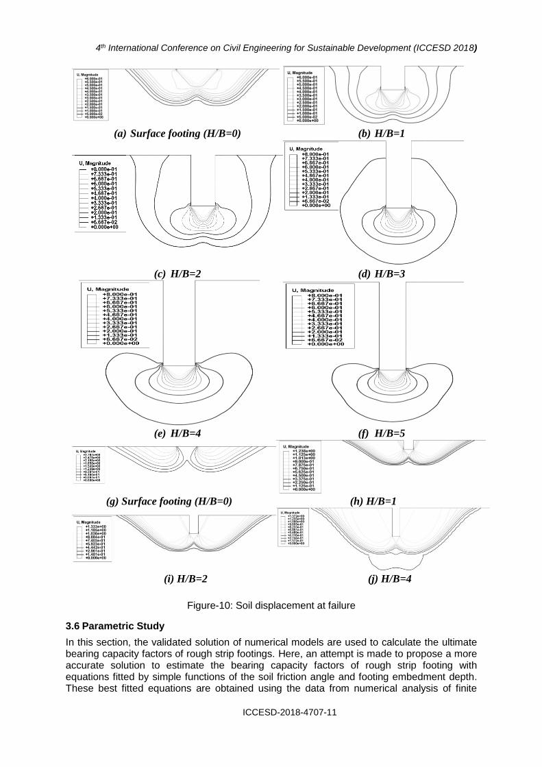
Here, Figure-10 shows the line contours of resultant soil displacement at failure for each of the footings modeled at surface (H/B=0) and at different embedment ratios (fig.(b) through fig.(i)). Under plane strain conditions a distinct Prandtl –type (1921) mechanism is observed in the finite element analyses Fig.(a). The contours (fig.(b) through fig.(f)) show the failure mechanism of footing in clay soil (ϕ=0). These illustrate the variation in nature of the soil displacement de-pending on embedment ratios. The footings are subjected to a uniform vertical displacement; the contours of resultant displace-ment beneath the rough footing show that the soil moves uni-formly vertically downwards with no relative soil movement on the underside of the footing. The line contours of soil displacement extend in surface upto shallow embedment ratios (i.e., H/B=2). For deep footing (H/B>2), contours start at the corner of footing and do not extend into the surface. Fig.6g through fig. 6j represents the variation of failure mechanism for sandy soil (c=0 and ϕ=30°) at surface (fig.6g) and different embedment ratios (Ffig.6.h through fig.6j). In all embedment ratios contour line extend to the surface and a triangular wedge zone is observed beneath the footing. A triangular zone is started at the corner of footing and extended to the surface. This zone is also observed at all embedment ratios for frictional soil but, it does not exist in clay soil.
4th International Conference on Civil Engineering for Sustainable Development (ICCESD 2018)
ICCESD-2018-4707-11
(a) Surface footing (H/B=0) (b) H/B=1
(c) H/B=2 (d) H/B=3
(e) H/B=4 (f) H/B=5
(g) Surface footing (H/B=0) (h) H/B=1
(i) H/B=2 (j) H/B=4
Figure-10: Soil displacement at failure
3.6 Parametric Study
In this section, the validated solution of numerical models are used to calculate the ultimate bearing capacity factors of rough strip footings. Here, an attempt is made to propose a more accurate solution to estimate the bearing capacity factors of rough strip footing with equations fitted by simple functions of the soil friction angle and footing embedment depth. These best fitted equations are obtained using the data from numerical analysis of finite
4th International Conference on Civil Engineering for Sustainable Development (ICCESD 2018)
ICCESD-2018-4707-12
element system Abacus. Hence, estimating the ultimate bearing capacity will be much more accurate and easier than previous empirical equations. Proposed equations for bearing capacity factors are: Nc = 3.15 * exp( 4.56*φ + 0.17*H/B ) (1) Nq = 0.88 * exp( 6.00*φ + 0.15*H/B ) (2)
N = 0.4 * exp( 7.75*φ + 1.23 ) (3)
4. CONCLUSIONS
• Frictional angle and embedment depth has huge impact over bearing capacity factors.
• All the bearing capacity factors are proportional to embedment depth. When
embedment depth increases, value of bearing capacity factors also increase.
• All the bearing capacity factors are also proportional to the friction angle of the
medium. When friction angle increases, bearing capacity also increases.
• Footing at higher embedment depth and higher frictional medium will ensure higher
bearing capacity.
REFERENCES
Cerato, A. B., & Lutenegger, A. J. (2007). Scale effects of shallow foundation bearing capacity on granular material. Geotechnical and Geoenvironmental Engineering, 133(10), 1192–1202.
Chen, W. F. (1975). Limit analysis and soil plasticity. Elsevier. Hansen, J. B. (1970). A revised and extended formula for bearing capacity. Geoteknisk Inst., Bulletin
28, 5–11. Kiran, M., & Bacha, N. (2015). An Experimental Study on Behaviour of Bearing Capacity and
Settlement of Circular and Square Footing Resting on Reinforced Sand Bed Stratified with Lateritic Soil. In International Journal of Engineering Research and Technology, (Vol. 4, N(ESRSA Publications.).
Kumar, J., & & Khatri, V. N. (2011). Bearing capacity factors of circular foundations for a general c–ϕ soil using lower bound finite elements limit analysis. International Journal for Numerical and Analytical Methods in Geomechanics, 35(3), 393–405.
Lavasan, A. A., & Ghazavi, M. (2012). Behavior of closely spaced square and circular footings on reinforced sand. Soils and Foundations, 52(1), 160–167.
Meyerhof, G. G. (1963). Some recent research on the bearing capacity of foundations. Canadian Geotechnical Journal, 1(1), 16–26.
Michalowski, R. L. (1997). An estimate of the influence of soil weight on bearing capacity using limit analysis. Soils Found., 37(4), 57–64.
Reissner, H. (1924). Zum erddruckproblem. In Proc. 1st Int. Congress for Applied Mechanics (pp. 295–311). Delft,The Netherlands.
Terzaghi, K. (1943). Theoretical soil mechanics. New York: Wiley. Vesic, A. S. (1973). Analysis of ultimate loads of shallow foundations. J. Soil Mech. Found. Div.,
99(1), 45–76. Zhu, M., & Michalowski, R. L. (2005). Shape factors for limit loads on square and rectangular footings.
Journal of Geotechnical and Geoenvironmental Engineering, 131(2), 223–231.