Page 1
University of Wisconsin MilwaukeeUWM Digital Commons
Theses and Dissertations
December 2014
The Effects of a Selected Wheel Design and CasterFixture Design on Pushing Force When PushingFour Wheeled Industrial CartsDavid WeinUniversity of Wisconsin-Milwaukee
Follow this and additional works at: https://dc.uwm.edu/etdPart of the Industrial Engineering Commons
This Thesis is brought to you for free and open access by UWM Digital Commons. It has been accepted for inclusion in Theses and Dissertations by anauthorized administrator of UWM Digital Commons. For more information, please contact [email protected] .
Recommended CitationWein, David, "The Effects of a Selected Wheel Design and Caster Fixture Design on Pushing Force When Pushing Four WheeledIndustrial Carts" (2014). Theses and Dissertations. 618.https://dc.uwm.edu/etd/618
Page 2
THEEFFECTSOFASELECTEDWHEELDESIGNANDCASTERFIXTUREDESIGNON
PUSHINGFORCEWHENPUSHINGFOURWHEELEDINDUSTRIALCARTS
by
DavidS.Wein
AThesisSubmittedin
PartialFulfillmentofthe
RequirementsfortheDegreeof
MasterofScience
inEngineering
at
TheUniversityofWisconsin‐Milwaukee
December2014
Page 3
ii
ABSTRACTTHEAFFECTSOFASELECTEDWHEELDESIGNANDCASTERFIXTUREDESIGNSON
PUSHINGFORCEWHENPUSHINGFOURWHEELEDINDUSTRIALCARTSby
DavidS.Wein
TheUniversityofWisconsin‐Milwaukee,2014UndertheSupervisionofDr.WilkistarOtieno
Manualmaterialhandlingstasks,manyofwhichrequirepushingandpulling
arecommoninalmostallindustrialandservicesectorenvironments.Thesetasks
exposeworkerstomusculoskeletalstressesaswellasotherrelatedslippingand
trippinghazards.Thecompanysponsorofthisstudysoughttolowertheriskof
injuryfrommanuallypushingandpullingcarts.Thecompanywantedtoevaluatea
newerstyleofsplitwheelandalsoanoffsetpivotdualorbitalcaster,whichthe
manufacturerstateswillreducepushingandpullingforce.Atotalofeight
participants(4male,4female)wereincludedinthestudy.Participantswere
requiredtopushafour‐wheeledcart16timesfor10meters.Thecartwaspushed8
timeswithatotalgrossweightof250lbs(113.4kgs)andanother8timeswith750
lbs(340.2kgs).Onlytherearwheelscouldswivelandweretestedboth
perpendicularandinlinetothedirectionoftravel.Thesplitwheelwascomparedto
asinglewheelandthedualorbitalcasterwascomparedtoastandardstyleofcaster.
Page 4
iii
Allpossiblecombinationsweretested.Appliedforcewasmeasuredandanalysis
wasconductedoninstantaneouspeakforce.
Resultsshowedthatthecasterdesigndidnotsignificantlyaffecttheinitial
appliedforce.However,thedualorbitalcasterwasconsistentintheamountof
appliedforcewhenthewheelswereperpendicularoralignedtothedirectionof
travel.Thedualorbitalcasterresultedinlowerinitialappliedforceswhenused
togetherwiththesinglewheeldesign.Inaddition,thedualorbitalcastershowed
markeddecreaseintheappliedpushforcewhenwheelswherepositioned
perpendiculartothedirectionoftravelcomparedtothestandardcaster.These
resultsstrengthentherecommendationforthecompanytoinvestinthedualorbital
–alsoreferredtooffsetpivotcaster.Secondly,thoughthewheeltypesignificantly
affectedtheappliedforcethemeanappliedforcedifferencebetweenthetwowheel
typeswasnotpracticallysignificantenoughtowarrantachangeofthewheeltypein
thecompany.
Page 5
iv
©CopyrightbyDavidS.Wein,2014AllRightsReserved
Page 6
v
Thisthesisisdedicatedtomywonderfulwifewhoencouragedmethroughoutthe
entireprogram.Itisalsodedicatedtomychildrenasareminderofthenecessityto
perseveretotheend.
Page 7
vi
TABLE OF CONTENTS
Contents
TABLEOFCONTENTS.............................................................................................................................vi
LISTOFFIGURES....................................................................................................................................viii
LISTOFTABLES........................................................................................................................................ix
ACKNOWLEDGEMENTS..........................................................................................................................x
Chapter1:ResearchBackground......................................................................................................1
Chapter2:LiteratureReview..............................................................................................................3
2.1Force/LoadGuidelines..............................................................................................................................3
2.2RelatedPriorResearch..............................................................................................................................4
2.3FactorsAffectingPullandPushForces............................................................................................12
Weight................................................................................................................................................13
Friction/WheelHardness..........................................................................................................13
WheelPosition/Orientation.....................................................................................................14
WheelDiameter.............................................................................................................................17
Slope...................................................................................................................................................17
HandleHeight.................................................................................................................................18
HandleWidth..................................................................................................................................18
Chapter3:CurrentStudy....................................................................................................................18
3.1StudyVariables...........................................................................................................................................18
3.2ResearchQuestions..................................................................................................................................20
3.3ResearchHypotheses...............................................................................................................................21
Chapter4:MethodologyandDataAnalysis...............................................................................22
4.1ExperimentParticipants.........................................................................................................................22
4.2EquipmentandInstrumentation........................................................................................................24
CartDesign.......................................................................................................................................24
Handle................................................................................................................................................27
CasterFixtures...............................................................................................................................27
Wheels...............................................................................................................................................28
CartLoad...........................................................................................................................................29
Floor....................................................................................................................................................30
DataCollectionElectronics.......................................................................................................31
Page 8
vii
Calibration........................................................................................................................................31
RatingsofPerceivedExertionScale......................................................................................32
4.3StudyDesign................................................................................................................................................32
4.4ExperimentalProcedure.........................................................................................................................34
4.5StatisticalAnalysis....................................................................................................................................36
Chapter5:ResultsandDiscussions...............................................................................................37
5.1Results............................................................................................................................................................37
DataProcessing..............................................................................................................................37
AnalysisofPhysicalMeasures–PeakForce.....................................................................38
PsychophysicalSelfReportedExertionData....................................................................39
5.2ParticipantData/Information..............................................................................................................39
5.3PhysicalForceMeasurementAnalysis–InitialPushForce......................................................40
5.4PsychophysicalAnalysisofPerceivedExertion............................................................................49
Chapter6:Discussion............................................................................................................................58
6.1HypothesisDiscussion.............................................................................................................................58
6.2VariabilityBetweenSubjects................................................................................................................62
6.3PerceivedExertion....................................................................................................................................63
6.4ApplicationoftheResults/PsychophysicalApplication............................................................64
6.4.1Scenario1–ChangingFixtures....................................................................................64
6.5LimitationsoftheStudy..........................................................................................................................65
6.5.1InstantaneousPeakForce..............................................................................................65
6.5.2LateralForce........................................................................................................................65
6.6ContributiontotheBodyofKnowledge...........................................................................................65
6.7FutureStudies.............................................................................................................................................66
Chapter7:Conclusion...........................................................................................................................66
References..................................................................................................................................................68
Appendices................................................................................................................................................71
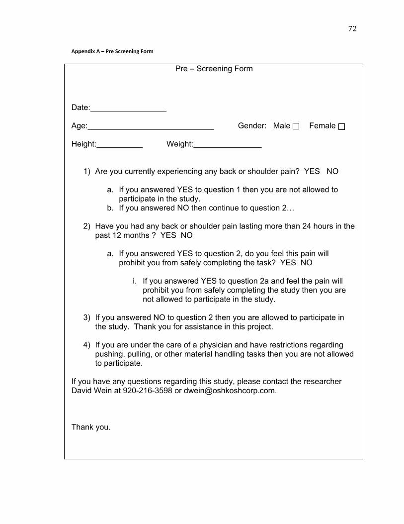
Appendix A – Pre Screening Form.................................................................................................................72
Appendix B – Participant Information..........................................................................................................73
Appendix C – Pain and Exertion Rating........................................................................................................74
Page 9
viii
LIST OF FIGURES
Figure 1 ‐ Wheel Positions.....................................................................................................................15Figure 2 ‐ Swivel Eaz Wheel...................................................................................................................19Figure 3 ‐ Cart design...............................................................................................................................25Figure 4 ‐ Handle Notches......................................................................................................................26Figure 5 ‐ Swivel Eaz Pro Figure 6 ‐ Standard Swivel Caster (Fixture).........................28Figure 7 ‐ Swivel Eaz Caster...................................................................................................................29Figure 8 ‐ Single Wheel...........................................................................................................................29Figure 9 ‐ Wheel/Fixture Orientation................................................................................................33Figure 10 ‐ Example of Graph of Push Force...................................................................................38Figure 11 ‐ Boxplot Gender Effect – Females versus Males.......................................................40Figure 12 ‐ General Linear Model........................................................................................................41Figure 13 ‐ ANOVA: Max Peak Initial Force vs Wheel Type & Wheel Position....................42Figure 14 ‐ Main Effects Plots...............................................................................................................43Figure 15 ‐ Interaction Plot....................................................................................................................43Figure 16 ‐ ANOVA....................................................................................................................................45Figure 17 ‐ Main Effects Plot.................................................................................................................46Figure 18 ‐ Interaction Plot....................................................................................................................47Figure 19 ‐ ANOVA, Fixture ‐ Wheel Type........................................................................................48Figure 20 ‐ Main Effects Plot, Fixture ‐ Wheel Type ‐ Wheel Position....................................48Figure 21 ‐ Interaction Plot; Fixture ‐ Wheel Type ‐ Wheel Position.......................................49Figure 22 ‐ Pearson’s Correlation, Back – Shoulder ‐ Weight....................................................50Figure 23 ‐ Normal Probability, Shoulder and Back......................................................................51Figure 24 ‐ Box Cox ‐ Shoulder and Back Data Transformation................................................51Figure 25 ‐ ANOVA General Linear Model ‐ Shoulders................................................................53Figure 26 ‐ ANOVA General Linear Model – Back..........................................................................55Figure 27 ‐ Boxplot ‐ Peak Initial Force..............................................................................................60Figure 28 ‐ Summary of Box Plot of Combinations.......................................................................60
Page 10
ix
LIST OF TABLES
Table 1 ‐ Related Research.......................................................................................................................5Table 2 ‐ Additional Weight Added.....................................................................................................30Table 3 ‐ Experiment Design Combinations.....................................................................................35Table 4 ‐ Participant Information & Statistics.................................................................................39Table 5 ‐ Applied Peak Force Range...................................................................................................63
Page 11
x
ACKNOWLEDGEMENTS
Iwouldliketothankthefollowingpeoplefortheirguidance,mentoring,andfor
sharingtheirknowledgethroughouttheprocess:Dr.WilkistarOtieno,Dr.Jay
Kapellusch,andProf.ArunGarg.
IwouldalsoliketothankthefollowingOshkoshCorporationemployeesfortheir
contributioninthedesignandbuildofthecartandassistancewiththedata
collection:AndyGratton,RyanSchumacher,andJeffVolkman.
Page 12
1
Chapter 1: Research Background Manualmaterialhandlingtaskscanbefoundinmanyindustrialandservicesector
environments.Muchfocusandattentioninresearchhasbeengiventoreducingrisk
factorsassociatedwithliftingandloweringofparts,components,orboxesinthe
workplace.TheNationalInstituteofOccupationalSafetyandHealth(NIOSH)first
publishedtheirLiftingGuidein1981[2].Sincethattime,industryhasresponded
byworkingtoreducetheamountofmanuallifting,lowering,andcarryingfoundin
workplaces,oftenreplacingthosetaskswithpushingandpulling[3].Incertain
industries,pushingandpullingmaneuverscanaccountforanestimated50%ofthe
manualmaterialtasks[1].
Intheworkplace,overexertionfromanoutsidesourcewasrankedasthehighest
causeofdisablinginjuries.Theseinjuriesincludedthoseinvolvingpushing,pulling,
lifting,orthrowing.In2011,injuriesrelatedtomaterialhandlingcostbusiness
$14.2billionindirectexpenses[4].
Itisestimatedthat9‐20%oflowerbackinjuriesintheindustrialenvironmentare
associatedwithpushingorpullingtasks[5].InthestateofOhio,thetotalannual
costforbackinjuriesisover$100milliondollarswhiletheaveragecostofaback
injuryis$18,290peroccurrence[6].AccordingtothestateofTexasDepartmentof
Insurance,theaveragecostforabackinjuryis$15,000.Backinjuriesalsoaccount
for24%oftheworker’scompensationinjuriesinTexas[7].Inadditiontoincreasing
Page 13
2
riskofinjurytotheback,pushingandpullinghasledtoincreaseddiscomfortinthe
shouldersofworkerswhomanuallypushcartsonaregularbasis[8].Accordingto
NIOSH,approximately600,000employeesareafflictedwithbackinjuriesannually,
atacostofover$50billion[26].Anundocumentedbutbelievedtobesignificant
portionoftheseinjuriesandcostsareattributabletopushingandpullingtasks.
Thesponsorofthisstudy,amanufacturerofmediumandheavymilitarytrucks,
tacticalwheeledvehicles,andcommercialvehicleshasbeenworkingtoreduce
forcesofmanualpushingandpullingofcarts.Thecompanyseekstolowerinjuries
byreducingpushingandpullingforce,apresumedriskfactorforinjury[1].Inan
efforttoreducepushingandpullingforces,theyhavestartedpurchasingsplit
wheeledcastersmanufacturedbyAubinIndustriesofTracy,California.Inaddition
tothesplitwheelcasternamedSwivel‐Eaz™,AubinIndustriesandhasdevelopeda
newstyleofcasterfixturecalledaSwivel‐Eaz™Pro.Thesponsorofthestudyseeks
toverifythemanufacturer’sclaimsthatbothproductsreducetheforcerequiredto
pushorpullacart.
Thisresearchstudywasdesignedtorespondtothesponsoringcompany’sconcerns.
Weseektodetermineifthesplitwheelandoffsetpivotcasterindividuallyor
interactivelyhaveaneffectoneitherinitialorsustainedforcewhencomparedtoa
standardsinglewheelandcasterdesign.Torealizethisgoal,wesoughttotestthe
followingthreehypotheses,whichwillbediscussedindetailinChapter3ofthis
thesis.
Page 14
3
1.Split‐wheeldesignwillaffecttheinitialappliedpeakforcerequiredtomovea
fourwheeledcart
2.Theoffsetpivotcastermountingwillaffecttheinitialpeakappliedforcerequired
tomoveafourwheeledcart.
3.Thereisastatisticallysignificantinteractionbetweenwheeltypeandcastertype
ontheinitialappliedpeakforcerequiredtomoveafourwheeledcart.
Chapter 2: Literature Review
2.1 Force/Load Guidelines IntheUnitedStates,theOccupationalSafetyandHealthAdministration(OSHA)has
neitherestablishedasafethresholdontheweightofacartanditscontents,northe
maximumforceanindividualisallowedtopushorpull.Theoften‐usedguidelinein
generalindustryforpushingandpullingcomesfromthepsychophysicalresearch
thatwasconductedattheLibertyMutualResearchCenterbySnookandCirielloin
1991[9].TousethetablesdevelopedbySnookandCiriello,theusermustidentify
thefollowing:task(pushingorpulling),gender,heightofthehandswhilepushing
orpulling,frequencyofthetask,andthedistancetraveled.Thegoalistodesignthe
tasksoitcanbesafelyaccomplishedby75%and99%ofthefemaleandmale
workers,respectively[9].
Page 15
4
2.2 Related Prior Research Table1isachronologicalsummaryofpublishedresearchdirectlyorindirectly
relatedtothisstudy.
Page 16
Table 1 ‐ Related Research
5
Page 23
12
Thisstudyisdifferentfromothersthathavepreviouslybeenconductedasit
comparesthenewersplitwheeldesigntoastandardsinglewheelwhichis
commonlyusedinmanyindustries.Additionally,theSwivel‐Eaz™Proswivelcaster
wasrecentlypatentedandisnewtothemarket;thereforeithasnotbeenstudiedin
thepast.
Thisstudywillcontributetothebodyofknowledgebyfillinginthedearthof
researchthatspecificallystudiestheeffectofSwivelEaz™wheelsandSwivelEaz™
Procastersinthepushandpullforces.
2.3 Factors Affecting Pull and Push Forces Intheindustrialsetting,employeesmayberequiredtopushcartswithvarious
loads.Thereareseveraldifferentfactorsthatcontributetotheactualforcerequired
tomovethecartincluding:friction,wheelposition,wheeldiameter,wheelhardness,
floorslope,andthecartandcontentweight.Initialforceisdefinedastheforce
requiredtogetanobjectinmotionwhilesustainedforceistheforcerequiredto
keepanobjectinmotion[9].Alldataanalysisinthisstudywasconductedonthe
peakinstantaneousappliedforcerecordedduringtheinitialphasewhilethecart
wasbeingpushed.Forconvenienceinidentification,thepeakinstantaneousforceis
thehighestpointfoundinatenthofasecondintimeduringtheinitialpushing
phase.Hereinafter,thepeakinstantaneousforceisreferredtoaspeakapplied
forceorpeakforce.
Page 24
13
Weight
Inavehicleassemblyplant,workersmayberequiredtopushcartsthatarefullof
metalpartswhicharerelativelyheavy;ortheycouldpushasmallcartoflightweight
plasticcomponents.Attimes,workersmayberequiredtopushorpullloadsof
variousweightsincludingthosewhichmayrequirenearmaximalstrengthtomove.
Forinstance,Cirielloetal.(1999)analyzed25,291manualmaterialhandlingtasks
ofwhich1,879requiredpushingand1,866requiredpulling.Theyfoundthat28%
ofthepushingtasksrequiredforcesgreaterthan70lbs(311N)[15].Inyetanother
study,Resnick(1996)foundthatthemeanstaticpeakhorizontalforcewas75lbs
(335N)forwomenand139lbs(620N)formen.Thesepeakforceswerefound
withahandleheightofabout80%ofshoulderheight[16].Loadweightsthatare
transportedinmostindustriescanvaryupto3,300lbs(1,500kgs)whichfarexceed
therecommendweightlimitof496lbs(225kgs)forfourwheeledcartsand251lbs
(114kgs)fortwowheeledcarts[13]‐[14].Inthisstudy,twodifferentloadweights
wereused250lbs(113kgs)and750lbs(340kgs).
Friction/Wheel Hardness
Frictionisdefinedasa“forcethatactstoresisttherelativemotion(orattempted
motion)ofobjectsormaterialsthatareincontact”[27].Inwheeledcarts,friction
betweenthewheelandtheaxleandrollingresistancebetweenthefloorandthe
wheeldeterminetheamountofforcerequiredtomovethecart[1].Higherfriction
contributestoincreasedrollingresistanceandthusrelativelyhigherpushingand
pullingforces.Forthisreason,low‐frictionwheelbearings,andrelativelyhard
wheelsarepreferredwhenpushingandpullingcartswithheavierloads[10]‐[13].
Page 25
14
Therelationshipbetweentherollingresistance,friction,andloadisgovernedbythe
followingequation[28]‐[29]:
F=fxW/R
F=theforcerequiredtoovercometherollingfriction
f=thecoefficientofrollingfriction(unitsmustmatchsameunitsasR(radius))
W=Loadonthewheel
R=Radiusofthewheel
Ittakeslessforcetopushorpullhardwheelsthansoftwheelsduetoalowerrolling
friction[10].Softwheelsorpneumaticwheelstendtodevelopflatspotswhena
cartloadedwithaheavyweightisstoredforalongperiodoftime[13].
Wheel Position/Orientation
Whetherinthemanufacturingortheservicesectorenvironment,itiscommonto
findacartwithfourcastershavingonepositionedoneachcorner.Thereareother
casterconfigurationsthatcanbeusedwhendesigningacart,suchashavingasingle
orpairoffixedcastersinthecenterandaswivelcasteroneachofthefourcorners
whichallowsthecarttobepositionedandmaneuveredintotightspaces[12].Some
cartshavetwofixedcastersandtwoswivels,whileothershavefourswivels.Three
morecommonlyfoundwheelpositionsarelistedin(Figure1)where“R”represents
aridgedorfixedcasterand“S”isaswivelcaster.Wheelsinthestudywere
positionedasdepictedinFigure1b.
Page 26
15
Figure 1 ‐ Wheel Positions
(1a) (1b) (1c)
Isthisstudy,twoswivelcastersweremountedononeendofthecartnearestthe
handleandtwofixedcastersweremountedontheoppositeend.
ThemanufacturerDarcorCastersandWheels,definesSwivelCasterasabasiccaster
unitwiththeadditionofabearingthatallowsthecastertoswivelaboutavertical
axis[30].Oneoftheproblemswithhavingasetofswivelwheelsonacartis
occasionallythewheelsarenotalignedinthedirectionoftravel.Whenthis
happens,additionalforceisrequiredtogetthecartwheelstoswivelaroundand
becomeproperlyalignedinthedirectionoftravel.AccordingtoastudybyAl‐
Eisawietal.,whenfrontwheelsofacartwerealignedinthedirectionoftraveland
rearwheelswereperpendiculartothedirectionoftravel,minimumpullforcewas
19%higherthantheminimumpushforce.Thissuggeststhatswivelwheelsshould
beplacedintherearifthecartwillbeprimarilypushed[10].
Swivelwheelsaffecttheamountofforcerequiredwhenpushingorstoppingacart
[10].Al‐Eisawietal.alsofoundthatwhenthereartwoswivelcastersarealigned
perpendiculartothedirectionoftraveltheaverageforcewas13.1%higherthan
whenallfourcasterswerealignedinthedirectionoftravel.Inaddition,theyfound
R
R
R
R
S
S
R
R
SS
R
R
Page 27
16
thatwhenallfourswivelcasterswerealignedperpendiculartothedirectionof
traveltheaverageforcewas30.7%higherthanwhenallfourwerealignedtothe
directionoftravel.Asaresultoftheirstudy,theyfoundthatthesmallestforce
requiredtomovethecartwasrecordedwhenallfourwheelswerealignedinthe
directionoftravel.Additionally,thegreatestforcewasrecordedwhenallfour
wheelswerealignedperpendiculartothedirectionoftravel[10].Therefore,inthis
studythefrontwheelswerefixedtothedirectionoftravel,whiletherearwheels
werepositionedbothin‐lineandperpendiculartothedirectionoftravelaswillbe
reportedinthedesignofexperiment.
Afour‐wheeledcartneedstohaveatleasttwowheelsthatswiveltoallowittoturn.
Cartswithfourswivelwheelsrequiremoreforcetooperate[10].Theextraforce
requiredtooperateafour‐wheeledcartwithswivelwheelscouldberelatedtothe
additionalforcethatisappliedtokeepitundercontrolinthelateraldirection[1].
Inthisstudy,lateralforcewasmeasuredtodetermineifitdecreasedwithanyofthe
newcasterdesignsorcombinations.
Asfour‐wheeledcartsarecommonlyfoundinthecompanysponsoringthisstudy,a
four‐wheeledcartwasconstructedwithswivelwheelspositionedattherearclosest
tothehandle.
Page 28
17
Wheel Diameter
Generally,theeffectofwheeldiameteronthepushandpullforceismodeledusing
theequationdescribedintheprevioussectionentitledFriction;whereR=radius,W
=loadonthewheel,f=coefficientofrollingfriction,anF=forcerequiredto
overcomerollingfriction.
F=fxW/R
Thereforeifallotherfactorsareequal,bydoublingradiusofthewheel,pushand
pullforcewilldecreasebyhalf.Increasingthediameterofawheelcanbean
effectivemeasureinreducingtheforceneededtomoveacart.Inastudyofpushing
floor‐basedpatientliftingdevices,itwasfoundthattherewerehighersheerforces
intheuser’sbackwhenpushingthedevicewithsmallerdiameterwheelscompared
toasimilarliftingdeviceequippedwithlargerdiameterwheels[1].Irrespectiveof
thefloorsurface(carpetorconcrete),pullforcedecreasedwhenwheeldiameter
wasincreased[10].However,pushandpullforceisgreaterwithlargerwheels
whenswivelwheelsarenotalignedinthedirectionoftravel[10].Largerdiameter
wheelsareabletocrossoverbumps,holes,andotherobstructionsinthefloormore
effectivelythansmallerwheels[1].Inthisstudy,diametersofthewheelschosen
were6in.(15.2cm)becausethisdimensionisprimarilyusedinthesponsoring
company.Inaddition,withthisdiameter,anybumpsintheconcreteinthetesting
facilitywouldnotinterferewiththedatacollectionprotocol.
Slope
Insomegeneraltaskssuchasmovingproductsusingtwo‐wheeledhandcarts,stairs
andcurbscancreateanobstaclethatisdifficultforthecarttogetover.Anoption
Page 29
18
maybetoinstallaramptohelpnavigatethestepsorcurb;althoughanincreasein
slopewillcauseanincreaseinpushandpullforce.Itisrecommendedthatwhen
usingaramptheslopeshouldbekepttolessthan3.5%(2∘)[15].
Handle Height
Al‐Eisawiet.al(1999)reportednostatisticaldifferenceinpushforcewithaload
weightof160lbs(73kgs)atthreedifferenthandleheights;knuckle,elbow,
shoulder.However,thedifferencewassignificantataloadweightof399lbs(181
kgs).Pushforcerequiredwhenhandleheightwasattheshoulderlevelwas10%
lowerthanatelbowheight,andelbowheightwas10%lowerthanknuckleheight
[11].Thepreferredhandleheightforhorizontalpushingisataboutelbowheight
[13].Inaddition,biomechanicalresearchhasfoundcompressionforceontheL5/S1
vertebraewaslowestwhenhandleheightissetatelbowheight[16].
Handle Width
Handlewidthshouldbedesignednogreaterthan18in.(45.7cm).Widerhandles
mayplacehigherloadsontheweakershouldermuscles[13].Inthisstudy,the
handlewidthwasfixedat20in.(51cm).
Chapter 3: Current Study
3.1 Study Variables Thefollowingsummarizedvariableswereconsideredinthisstudy:(1)loadweight
(2)wheelalignment(3)casterfixturedesignand(4)wheeltype.
Page 30
19
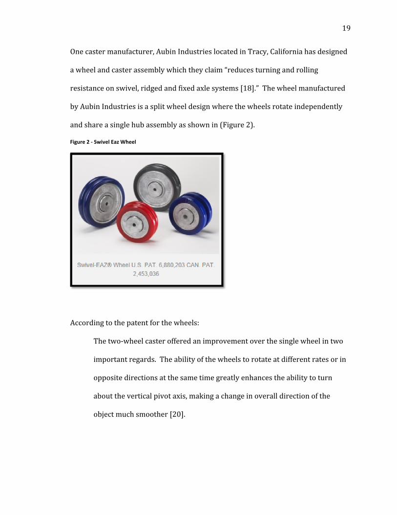
Onecastermanufacturer,AubinIndustrieslocatedinTracy,Californiahasdesigned
awheelandcasterassemblywhichtheyclaim“reducesturningandrolling
resistanceonswivel,ridgedandfixedaxlesystems[18].”Thewheelmanufactured
byAubinIndustriesisasplitwheeldesignwherethewheelsrotateindependently
andshareasinglehubassemblyasshownin(Figure2).
Figure 2 ‐ Swivel Eaz Wheel
Accordingtothepatentforthewheels:
Thetwo‐wheelcasterofferedanimprovementoverthesinglewheelintwo
importantregards.Theabilityofthewheelstorotateatdifferentratesorin
oppositedirectionsatthesametimegreatlyenhancestheabilitytoturn
abouttheverticalpivotaxis,makingachangeinoveralldirectionofthe
objectmuchsmoother[20].
Page 31
20
ThecasterassemblyalsomanufacturedbyAubinIndustries“allowsthecasterto
pivoteasilytoaccommodatethedirectionofthrustappliedtoanobjectsupported
bythecaster[20].”
Accordingtothepatentforthecaster:
Thisadvantageousfeatureismadepossiblebyprovidingadualpivot
assemblyinthecastermountingthatislaterallyoffset,wherebythecaster
wheelsmaynotonlypivotaboutawheelpivotaxisthatextendsthroughthe
planeofthecasterwheel,butalsorevolveorbitallyaboutamountingpivot
axisthatislaterallyoffsetfromthewheelaxis.Asaresult,thecaster
assemblyeasilymayassumetheproperorientationforanythrustappliedto
thecaster‐supportedobject[20].
3.2 Research Questions
Thisstudysoughttoanswerthefollowingquestions:
1.Doesthesplitwheelhaveaneffectoneitherinitialorsustainedforcewhen
comparedtoastandardsinglewheelinvariouscasterorientations?
2.Doestheoffset‐pivotfixture(caster)haveaneffectoneitherinitialorsustained
forcewhencomparedtoastandardcasterfixtureinvariouswheelorientations?
3.Dothesefactors:wheeltype(splitversussingle),fixture(standardversusoffset),
andwheelorientation(alignedversusmisaligned)haveaninteractiveeffectonthe
pushforces?
Page 32
21
3.3 Research Hypotheses TheoverarchinggoalofthisresearchistodeterminetheefficacyoftheSwivelEaz™
splitwheelandoffsetpivotalSwivelEaz™Procasterinreducingpushforcesthat
occurwhenmanuallymovingacart.Torealizethisgoal,wesetupthreemainaims
fromwhichwedefinedtheresearchhypothesisasfollows:
1.Split‐wheeldesignwillaffecttheinitialappliedpeakforcerequiredto
moveafourwheeledcart.
Hypothesis1a:Splitwheelswillreducetheinitialappliedpeakforcewhen
therearwheelsarepositionedat90degreestothedirectionoftravel.
Hypothesis1b:Splitwheelswillaffecttheinitialappliedpeakforcewhenthe
rearwheelsarepositionedat0degrees(alignedwiththedirectionoftravel).
2.The“offsetpivot”castermountingwillaffecttheinitialpeakappliedforce
requiredtomoveafourwheeledcart.
Hypothesis2a:Theoffsetpivotcastermountingwillreducetheinitial
appliedpeakforcerequiredtomovethecartwhentherearwheelsare
positionedat90degreestothedirectionoftravel.
Hypothesis2b:Theoffsetpivotcastermountingaffecttheinitialapplied
peakforcewhentherearwheelsarepositionedat0degrees(alignedwith
thedirectionoftravel).
3.Thereisastatisticallysignificantinteractionbetweenwheeltypeandcaster
typeontheinitialappliedpeakforcerequiredtomoveafourwheeledcart.
Hypothesis3a:Thereisastatisticallysignificantinteractionbetweenwheel
typeandcastertypeontheinitialappliedpeakforcerequiredtomoveafour
Page 33
22
wheeledcartwhentherearwheelsarepositionedat90degreestothe
directionoftravel.
Hypothesis3b:Thereisastatisticallysignificantinteractionbetweenwheel
typeandcastertypeontheinitialappliedpeakforcerequiredtomoveafour
wheeledcartwhentherearwheelsarepositionedat0degrees(alignedwith
thedirectionoftravel).
Chapter 4: Methodology and Data Analysis
4.1 Experiment Participants Inordertobeginconductingthestudyonhumansubjects,approvalwasobtained
fromtheUniversityofWisconsin‐MilwaukeeInstitutionalReviewBoard(IRB).
FinalapprovaltobeginthisstudyIRB#14.316wasgivenonAugust13,2014for
oneyear.Whileeightparticipantswasthetargetgroupsize,theIRBalloweda
totaloftwelvesubjectstoparticipateinthestudytoallowforpossibleparticipant
withdrawal.
Eightprofessionalworkers(4male,4female)ofvariousagesandoccupationswere
recruitedtoparticipateinthestudy.Allofthesubjectswereemployeesoftheheavy
truckandmilitaryvehiclemanufacturerthatsponsoredthestudyandacceptedto
jointhestudyvoluntarily.Allofthesubjectsworkedinaprofessionaloffice
environment.
Page 34
23
Subjectscompletedthestudyduringtheirnormalworkday;therebyreceivingtheir
standardwage.Noovertimewaspaidtoparticipantsnorweretheypaidanything
beyondtheirnormalwage.Participantswhosuccessfullycompletedthestudy
receiveda$40creditcard,whichwasapprovedbytheUWMIRBcommittee.Before
subjectswereallowedtoparticipateinthestudytheycompletedapre‐screenform
(AppendixA)aswasstipulatedbytheIRBinclusion/exclusionprotocol.Thepre‐
screenformaskedthepotentialparticipantiftheyhadanypreviousinjuriesintheir
backorshouldersoriftheywereatthetimeexperiencinganypainordiscomfortin
theirbackorshoulders.Iftheyansweredyestoanyofthesequestionstheywould
beprecludedfromparticipatinginthestudy.Iftheparticipantsuccessfullypassed
thescreeningprocesstheyweregiventheUWM‐IRBcommitteeapprovedconsent
formforreviewandsignature.Thestudentprincipalinvestigatormetwith
supervisorsofeachpotentialparticipanttoobtainapprovalfortheiremployeesto
participateinthestudy.Testingwasconductedonsiteatthesponsoringcompany's
testanddevelopmentfacility.
Afterthesubjectreviewedandsignedtheconsentformtheywerereadyto
participateinthestudy.Ashortdemographicandanthropometricformwas
completedthatincludedheight,weight,genderandstandingelbowheight
(AppendixB).Participantswereaskedtoprovidetheiroverallstature.Standing
elbowheightwasmeasuredinthelab.Thesemeasurementsweretakenwiththeir
shoeson.
Page 35
24
Subjectswereaskedtopushthecartoncefor10metersforeachofthe16test
combinations.Testingoccurredovertwoseparatesessionsforatotalof8trials
eachsession.Tominimizetheeffectofmusclefatigue,subjectswereallowedtorest
2minutesbetweentrialsandweregivenupto5minutesbetweentrialsifnecessary.
Inaddition,therewasalongerrest/recoveryperiodofatleast2daysbetweenthe
initial8trialsandthelater8trials.Voltage,speed,andtimewerecollectedduring
eachofthetrialsandtheexperimentcombinationrunswererandomizedusinga
randomnumbergeneratoravailableonlineatrandom.org.
Thefloorofthetestfacilityisapouredconcretepad,whichisrepresentativeofthe
floorsurfacefoundinmanyfactories.Tomaximizeforwardforceandminimize
downwardforce,handleheightwasadjustedtothesameheightastheparticipant’s
standingelbowheight.
4.2 Equipment and Instrumentation
Cart Design
Toreducesetuptimebetweentrials,twocarts(hereinnamedcart1and2)were
builttothesamedimensionsusingthesameconstructionmaterialsfoundinFigure
3.
Page 36
25
Figure 3 ‐ Cart design
Thecartswerebuiltusing1in.(2.5cm)rectangularsteelstockwhichwerewelded
togetheratthejoints.Thetotaldimensionsofthecartplatformmeasure24in.(61
cm)x36in.(91cm).A24in.(61cm)x36in.(91cm)x¾in.(2cm)thicksheetof
plywoodwasscrewedtothetopoftheplatformframetoprovideasolidsurfacefor
theweights.Toallowforaquickersetuptimebetweentrials,thestandardcaster
fixtureswereinstalledononecartandtheSwivelEaz™Procasterfixtureswere
installedonthesecondcart.Therefore,toreducesetuptimebetweentrials,either
theweightorthewheelshadtobechanged,nevertheentirefixture.
Page 37
26
Thehandlewasbuiltusing¾in.(2cm)roundsteelcutandweldedtothe¾in.(2
cm)squaresteelstock.Overalldimensionofthehandleis20in.(51cm).The
verticalsupportforthehandlewasbuiltusinga¾in.(2cm)x¾(2cm)steelsquare
tubethatmeasures40in.(102cm)inlength.Theverticalsupportwasinsertedinto
a1in.(2.5cm)x1(2.5cm)squaretubewhichmeasured14in.(35.6cm)intotal
length.Holesweredrilledthroughthe1in.(2.5cm)x1in.(2.5cm)squaretube
every1in.(2.5cm)andapinwasinsertedtosupporttheverticalhandlestructure.
Thisallowedthehandletoadjustverticallytomatchstandingelbowheightofeach
participant.Thehandlewasdesignedtobeeasilyremovedandwassharedbetween
thetwocarts.Theverticalsupportforthehandlewasnotchedonall4edgesto
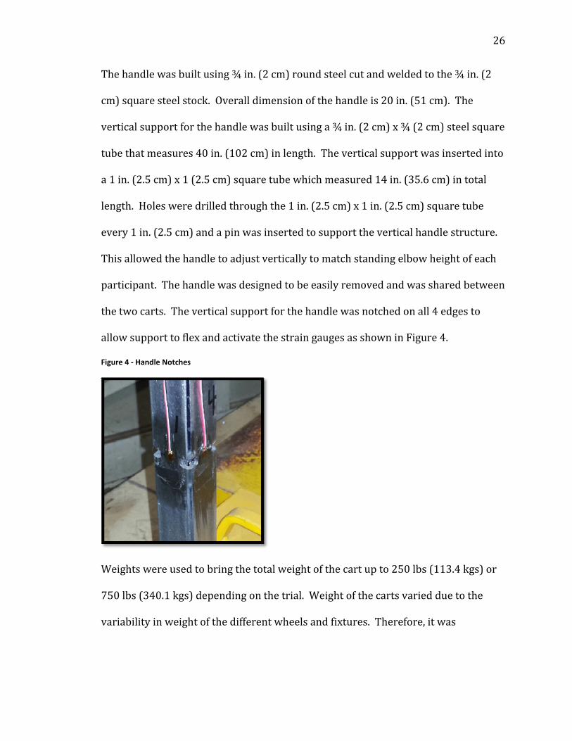
allowsupporttoflexandactivatethestraingaugesasshowninFigure4.
Figure 4 ‐ Handle Notches
Weightswereusedtobringthetotalweightofthecartupto250lbs(113.4kgs)or
750lbs(340.1kgs)dependingonthetrial.Weightofthecartsvariedduetothe
variabilityinweightofthedifferentwheelsandfixtures.Therefore,itwas
Page 38
27
necessarytoincorporateadditionalsmallerweightstothecarttobringthetotal
weight(cartandload)uptothetarget.
Whilecartloadweightvariesinthesponsoringcompanymanufacturing
environment,thesetwoweightlevelswereselectedastheyarerepresentativeof
theloadweightrangethatcouldexistinaheavy‐vehiclemanufacturing
environment.Preliminaryforcetestingwascompletedusingahandheldforce
measurementdevice(ergoFET300manufacturedbyHogganHealth).Toestablish
themaximumpushforcethattheparticipantsinthisstudycouldexperience,a
preliminarytestwasconductedintheworst‐casescenariowithwheelsaligned
perpendiculartothedirectionoftravelandthecartwaspushedtoahighvelocity.
Thisinitialtestresultedinforcesthatdidnotexceed50lbs.(222N),whichwaswell
belowthemeanstaticforceforbothwomenandmenreportedbyResnick,(1996)
[16].
Handle
Thehandlewasdesignedtobeadjustable,hencetoberaisedorloweredto
accommodatethestandingelbowheightforeachsubject.Toaccommodate98%of
theworkingpopulation[24]thehandlewasdesignedsothatitcouldbeloweredto
37in(94cm)andraisedto48in(122cm).
Caster Fixtures
AllofthecasterfixturesweremanufacturedbyAubinIndustries.Thedualoffset
swivelfixturenamedtheSwivelEaz™Proandhastwoseparatepivotorswivel
Page 39
28
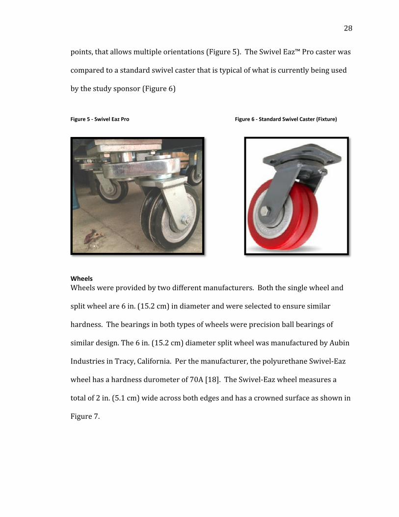
points,thatallowsmultipleorientations(Figure5).TheSwivelEaz™Procasterwas
comparedtoastandardswivelcasterthatistypicalofwhatiscurrentlybeingused
bythestudysponsor(Figure6)
Figure 5 ‐ Swivel Eaz Pro Figure 6 ‐ Standard Swivel Caster (Fixture)
Wheels
Wheelswereprovidedbytwodifferentmanufacturers.Boththesinglewheeland
splitwheelare6in.(15.2cm)indiameterandwereselectedtoensuresimilar
hardness.Thebearingsinbothtypesofwheelswereprecisionballbearingsof
similardesign.The6in.(15.2cm)diametersplitwheelwasmanufacturedbyAubin
IndustriesinTracy,California.Perthemanufacturer,thepolyurethaneSwivel‐Eaz
wheelhasahardnessdurometerof70A[18].TheSwivel‐Eazwheelmeasuresa
totalof2in.(5.1cm)wideacrossbothedgesandhasacrownedsurfaceasshownin
Figure7.
Page 40
29
Figure 7 ‐ Swivel Eaz Caster
Thestandardstylesinglewheelwhichalsomeasures2in.(5.1cm)wideand6in.
(15.2cm)indiameterismanufacturedbyArbcoIncorporated(Figure8).Itisa
phenolicwheelandhasasimilarhardnessastheSwivel‐Eazsplitwheel.
Figure 8 ‐ Single Wheel
Cart Load
Steel weights were used to bring the gross weight of the cart up to 250 lbs (113.4 kgs) or
750 lbs (340.2 kgs) depending on the trial. The weight of the carts varied due to the
Page 41
30
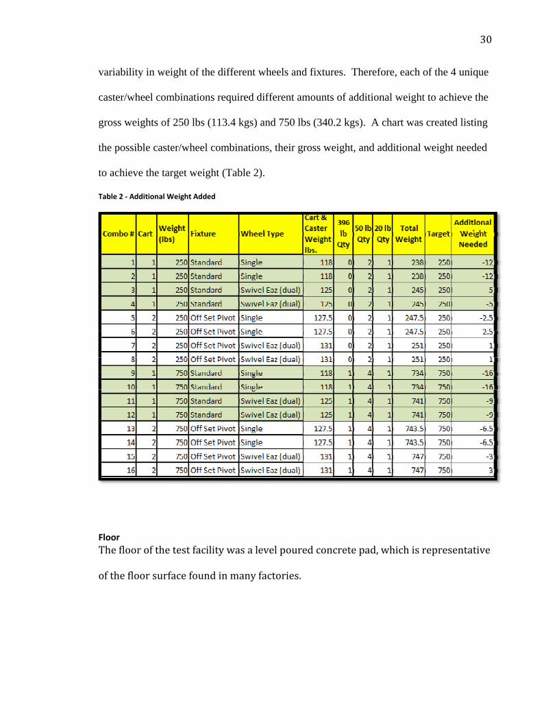
variability in weight of the different wheels and fixtures. Therefore, each of the 4 unique
caster/wheel combinations required different amounts of additional weight to achieve the
gross weights of 250 lbs (113.4 kgs) and 750 lbs (340.2 kgs). A chart was created listing
the possible caster/wheel combinations, their gross weight, and additional weight needed
to achieve the target weight (Table 2).
Table 2 ‐ Additional Weight Added
Floor
Thefloorofthetestfacilitywasalevelpouredconcretepad,whichisrepresentative
ofthefloorsurfacefoundinmanyfactories.
Page 42
31
Data Collection Electronics
Thehandlesupportwasnotchedatallfouredgesat18in.(45.7cm)fromthe
bottom.Straingaugesweremountedonallfoursidesofthehandletoallowfor
measuringforceinthreeaxis:(X)laterally,(Y)longitudinally,(Z)andvertically.
Thefourstraingaugesweremountedtotheverticalhandlewithtapeandusedto
measuredeflectionofthehandleunderload.Thefourstraingaugeswerewiredtoa
5‐channelbridgecompletionmodule.Thebridgecompletionmodulewas
connectedtotheVbox3andwassetuptorunatasamplingrateof10Hz.Datawas
savedonacompactflashmemorycard.Aphotosensorwasmagneticallyattached
tothefrontwheelandcapturedspeedbyemittinglightontherotatingwheeland
countingthemarkers.Thewheelrotationdatawasalsorecordedandlater
convertedtospeedinmilesperhour.Thephotosensorwasalsoconnectedtothe
Vbox.
Calibration
Tocalibratethestraingaugesthecartwasaffixedtoabedplate.Anoverhead
bridgecranewasusedtosupporta500lbloadcellwhichwasattachedtoaratchet
device.TheratchetwasusedtopullagainstthecartinX,Y,Zorientations.The
testswereconductedin10lbincrementsfrom0to100lbs.Bendingofthehandle
wasmeasuredandrecorded.Loadversusstrainwasrecordedandusedtodevelop
aregressiontoallowforthedataconversion.Thewheelopticalreaderwasalso
calibrated.
Page 43
32
Ratings of Perceived Exertion Scale
Afterpushingthecart,theparticipantcompletedaperceivedphysicalexertion
questionnaire(AppendixC).Perceivedexertionisaresponsevariableandrated
usingtheBorgCR10scale.Attheendofeachtrial,participantswereaskedtorate
thelevelofexertiontotheirshouldersandback,usingtheBorgCR10scale[22].
TheBorgCR10scaleisacategoricalpsychophysicalscalethatprovidesaratingof
perceivedexertion(RPE).Thisscalehasbeenusedwidelyinavarietyof
applicationssuchasrehabilitationandsportstrainingtoassesstheintensityofa
givenphysicalprocedure[23].Additionally,theywereaskedtoratehowwellthey
likedordislikedthewheelandfixturecombination,subjecttoeaseofoperation.
4.3 Study Design Thepurposeoftheresearchwastoinvestigatetheeffectsofthesewheelandfixture
designsonpushingforceofafour‐wheeledcart.Weuseda24balancedfullfactorial
experimentdesign,with8participants(fourmaleandfourfemale).Each
participantwasaskedtopushthecartforeachofthecombinations(foratotalof
128experimentruns).Inbrief(detailswillbediscussedinthemethodology
chapter),thevariablesthatwereconsideredinclude:(i)astandardcommonlyused
2in.(5.1cm)thick,6in.(15.2cm)diametersinglewheelversusa2in.(5.1cm)
thick,6in(15.2cm)diametersplitwheel(Swivel‐Eaz™),(ii)astandardswivel
casterversustheoffset‐pivotorbitalcaster(Swivel‐Eaz™Pro),(iii)representative
loadweightlevelsof250lbs(113.4kgs)and750lbs(340.2kgs),and(iv)rearwheel
position(0degreei.e.alignedtothedirectionoftravel)versus90degrees
(perpendiculartothedirectionoftravel).Itmustbenotedthatallwheel,fixture,
Page 44
33
andweightcombinationsweretestedwiththefrontwheelsfixedon0degreesto
directionoftravel.Tokeepthestudyfocusedondeterminingpushforcewith
wheelsalignedinthedirectionoftravelandalsopositionat90degreesor
perpendiculartothedirectionoftravel,pushingthecartaroundacornerwasnot
consideredinthisstudy.
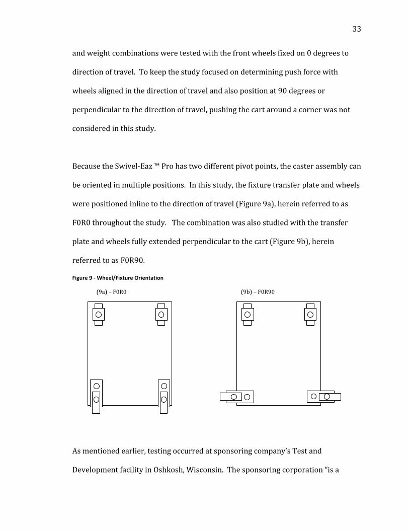
BecausetheSwivel‐Eaz™Prohastwodifferentpivotpoints,thecasterassemblycan
beorientedinmultiplepositions.Inthisstudy,thefixturetransferplateandwheels
werepositionedinlinetothedirectionoftravel(Figure9a),hereinreferredtoas
F0R0throughoutthestudy.Thecombinationwasalsostudiedwiththetransfer
plateandwheelsfullyextendedperpendiculartothecart(Figure9b),herein
referredtoasF0R90.
Figure 9 ‐ Wheel/Fixture Orientation
(9a)–F0R0 (9b)–F0R90
Asmentionedearlier,testingoccurredatsponsoringcompany’sTestand
DevelopmentfacilityinOshkosh,Wisconsin.Thesponsoringcorporation“isa
Page 45
34
leadingmanufacturerandmarketerofaccessequipment,specialtyvehiclesand
truckbodiesfortheprimarymarketsofdefense,concreteplacement,refusehauling,
accessequipmentandfireandemergency[22].”
4.4 Experimental Procedure Subjectsparticipatedintwo60minutesessions.Aminimumof24hoursofrestwas
providedbetweeneachsession.Atthebeginningofthefirstsession,eligible
subjectscompletedashortdemographicandanthropometricform(AppendixC)
thatincludedheight,weight,genderandstandingelbowheight(measuredinthelab
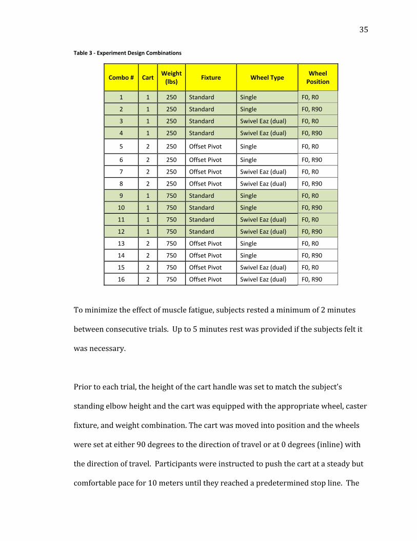
withshoeson).Subjectsthencompletedthe16pushandpulltrials(Table3)in
randomorder,with8trialsperformedineachsession.
Page 46
35
Table 3 ‐ Experiment Design Combinations
Combo # Cart Weight (lbs)
Fixture Wheel Type Wheel Position
1 1 250 Standard Single F0, R0
2 1 250 Standard Single F0, R90
3 1 250 Standard Swivel Eaz (dual) F0, R0
4 1 250 Standard Swivel Eaz (dual) F0, R90
5 2 250 Offset Pivot Single F0, R0
6 2 250 Offset Pivot Single F0, R90
7 2 250 Offset Pivot Swivel Eaz (dual) F0, R0
8 2 250 Offset Pivot Swivel Eaz (dual) F0, R90
9 1 750 Standard Single F0, R0
10 1 750 Standard Single F0, R90
11 1 750 Standard Swivel Eaz (dual) F0, R0
12 1 750 Standard Swivel Eaz (dual) F0, R90
13 2 750 Offset Pivot Single F0, R0
14 2 750 Offset Pivot Single F0, R90
15 2 750 Offset Pivot Swivel Eaz (dual) F0, R0
16 2 750 Offset Pivot Swivel Eaz (dual) F0, R90
Tominimizetheeffectofmusclefatigue,subjectsrestedaminimumof2minutes
betweenconsecutivetrials.Upto5minutesrestwasprovidedifthesubjectsfeltit
wasnecessary.
Priortoeachtrial,theheightofthecarthandlewassettomatchthesubject’s
standingelbowheightandthecartwasequippedwiththeappropriatewheel,caster
fixture,andweightcombination.Thecartwasmovedintopositionandthewheels
weresetateither90degreestothedirectionoftravelorat0degrees(inline)with
thedirectionoftravel.Participantswereinstructedtopushthecartatasteadybut
comfortablepacefor10metersuntiltheyreachedapredeterminedstopline.The
Page 47
36
Vboxdatacollectionunitwassettorecordtheforce(ie,calibratedvoltage),speed,
andtimeduringthetrial.
AftereachtrialthesubjectcompletedthePainandExertionratingform(Appendix
C),andprovidedtheirsubjectivefeedbackabouthowwellthey“liked”the
fixture/wheelcombination.Finally,theresearcherrecordedtheVBoxtrialnumber
onthePainandExertionratingformandreturnedthecarttothestartline.
4.5 Statistical Analysis AppliedpeakforcedatawasprocessedinMicrosoftExcel2007.Handlebending
datawasconvertedtopoundsofforceinlateralandlongitudinaldirections.Force
wasalsorecordedintheverticaldirection;howeverduetoalimitationinthedesign
ofthecarthandlethestraingaugewasnotabletorecordverticaltensionaccurately.
Therefore,only2axisofdatawereused,lateral(sidetoside),andlongitudinal
(fronttoback).
Sincea24fullyrandomizedfactorialdesignwasused,thepeakforcemeasurements
wereanalyzedwithageneralizedlinearmodelusingabackwardseliminationusing
Minitabversion17.Minitabperformsastepwiseregressionwithbackward
eliminationbystartingwithallpredictorsinthemodelandremovestheleast
significantvariableforeachstepandeventuallystopswhenthep‐valueislessthan
orequaltothespecified“Alpha‐to‐Removevalue”[31].
Page 48
37
PsychophysicalselfreportedexertiondatawasanalyzedusingaPearson’s
Correlationcoefficient.Analysiswasconductedtounderstandrelationshipbetween
thevariablesandperceivedexertionontheshoulderandback.
Chapter 5: Results and Discussions
5.1 Results
Data Processing
Samplingdatawascollectedforeachtrialrunandsavedinitsrawformat.Datawas
collectedfromeachofthe4straingauges,pulsedataforthewheelrotation,and
time.Next,voltagefromthestraingaugeswasconvertedintolongitudinaland
lateralbendingloadinpoundsofforce.Rootmeansquare(RMS)valuewas
calculatedusingthelateralandlongitudinalbendingload.Verticalloadwas
recordedanddiscardedandwasnotusedinthecalculation.Thedesignofthe
handleandplacementofthestraingaugesdidnothaveenoughsensitivityto
accuratelycaptureverticalloadinthedownwardorupwardmotion.Inthisstudy,
verticalloadwasminimizedashandleheightwasadjustedtostandingelbowheight
foreachparticipant.
Pulsedatafromthewheelwasconvertedtorevolutionperminutethenultimately
convertedtomilesperhour.Onceallofthedatawasconvertedintotherequired
formatandunitsofmeasure,datawasplottedinMicrosoftExcelonascatterplot
withstraightlinesasshowninFigure10.EvidentinFigure10,forcevaluesbecame
Page 49
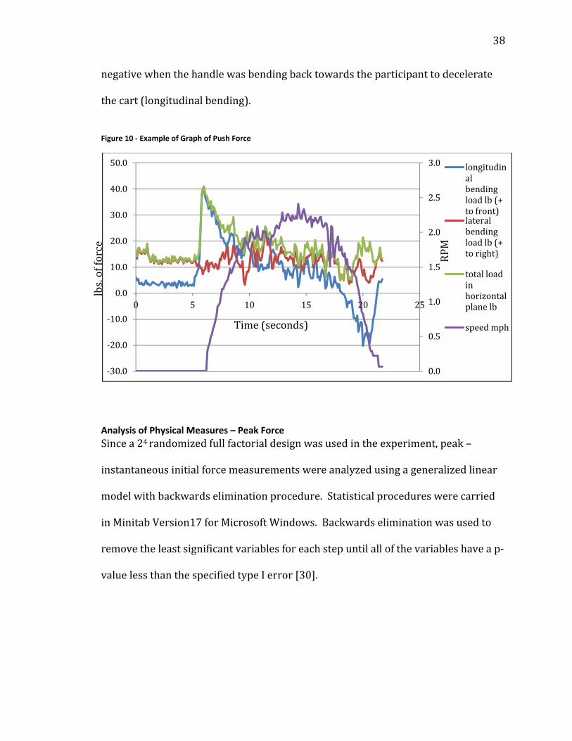
38
negativewhenthehandlewasbendingbacktowardstheparticipanttodecelerate
thecart(longitudinalbending).
Figure 10 ‐ Example of Graph of Push Force
Analysis of Physical Measures – Peak Force
Sincea24randomizedfullfactorialdesignwasusedintheexperiment,peak–
instantaneousinitialforcemeasurementswereanalyzedusingageneralizedlinear
modelwithbackwardseliminationprocedure.Statisticalprocedureswerecarried
inMinitabVersion17forMicrosoftWindows.Backwardseliminationwasusedto
removetheleastsignificantvariablesforeachstepuntilallofthevariableshaveap‐
valuelessthanthespecifiedtypeIerror[30].
0.0
0.5
1.0
1.5
2.0
2.5
3.0
‐30.0
‐20.0
‐10.0
0.0
10.0
20.0
30.0
40.0
50.0
0 5 10 15 20 25
longitudinalbendingloadlb(+tofront)lateralbendingloadlb(+toright)
totalloadinhorizontalplanelb
speedmph
lbs.offorce
Time(seconds)
RPM
Page 50
39
Psychophysical Self Reported Exertion Data
APearsoncorrelationtestwasrunonthepsychophysicalperceivedexertiondatato
determinethepresenceorabsenceofcorrelationbetweentheperceivedexertion
dataandtheinitialforce.Thiscorrelationwasvalidatedbyaddingweightasan
additionalcorrelationvariable.“Thelargertheabsolutevalueofthecorrelation
coefficient,thestrongerthelinearrelationshipbetweenthevariables[30]”.
5.2 Participant Data/Information Thefollowingchartprovidesanthropometricaswellasthedemographic
informationforthe8participantsincludingmeanandstandarddeviation(Table4).
Table 4 ‐ Participant Information & Statistics
Subject Gender Age Weight StandingElbowHeight
1 Male 29 195 47”
2 Male 26 185 44”
3 Male 49 215 44”
4 Male 45 183 43”
5 Female 57 125 42”
6 Female 43 200 42”
7 Female 48 189 41.5”
8 Female 38 190 42.5”
Range 26‐ 57 125‐ 215
MaleMean(std.dev)
37.3(9.9)
194.5(12.7)
FemaleMean(std.dev)
46.5(7.0)
176(29.8)
OverallMean(std.dev)
41.9(9.8)
185.3(24.7)
Page 51
40
Theboxplotsummary(Figure11)formaximuminitialforcebygendershowsthat
malesexertedmoreinitialforcewhenpushingthecartforboth250lbs(113.4kgs)
and750lbs(340.4kgs).
Figure 11 ‐ Boxplot Gender Effect – Females versus Males
(Figure 11a) (Figure 11b)
250 lbs (113.4 kgs) 750 lbs (340.4 kgs)
5.3 Physical Force Measurement Analysis –Initial Push Force UsingMinitab17,ageneralizedlinearmodelwasfittedtothedatafollowingthe
backwardeliminationprocedure,theresultsofwhicharesummarizedinFigure12.
Inthismodelfixture,wheeltype,wheelposition,andweightweretreatedasthe
mainfactorswhileparticipantsweretreatedasablockingfactortoaccommodate
theexpectedvariabilitywithinsubjects.
Page 52
41
Figure 12 ‐ General Linear Model
GeneralLinearModel:MaxPeakForversusWeight(lbs),WheelType,...MethodFactorcoding(‐1,0,+1)
BackwardEliminationofTermsCandidateterms:Weight(lbs),WheelType,Fixture,WheelPosition,Participant ‐‐‐‐‐Step1‐‐‐‐ ‐‐‐‐‐Step2‐‐‐‐ CoefP CoefPConstant 31.316 31.317Weight(lbs) ‐9.2490.000 ‐9.2500.000WheelType ‐1.1480.068 ‐1.1480.067Fixture ‐0.2230.721WheelPosition ‐1.5450.014 ‐1.5450.014Participant 12.300.000 12.310.000S 7.03694 7.01067R‐sq 76.96% 76.93%R‐sq(adj) 74.77% 74.96%R‐sq(pred) 71.95% 72.39%Mallows’Cp 12.00 10.13αtoremove=0.1
Givena90%confidencelevel,itwasfoundthatonlywheeltype,wheelposition,
weight,andparticipantsignificantlyaffectedtheinitialpushforce.Inthefollowing
sectionwepresentanddiscusstheresultsoftheanalysisthatwerecarriedoutto
testeachofthethreehypotheses.
Page 53
42
Testofhypothesis1:
1.Split‐wheeldesignwillaffecttheinitialappliedpeakforcerequiredto
moveafourwheeledcart.
Hypothesis1a:Splitwheelswillreducetheinitialappliedpeakforcewhen
therearwheelsarepositionedat90degreestothedirectionoftravel.
Hypothesis1b:Splitwheelswillaffecttheinitialappliedpeakforcewhenthe
rearwheelsarepositionedat0degrees(alignedwiththedirectionoftravel).
Figure13indicatesthattheinteractionbetweenwheeltypeandpositionhasap‐
valueof0.947,henceitisnotsignificant.However,bothfactorsareindividually
significant.Inthisanalysis,weightwastreatedasafixedfactor,whosesignificance
wasexpected.Toaccountfortheexpectedvariabilitywithinparticipants,the
participantvariablewastreatedasablockingfactor,whichalsoturnedouttobe
significant.
Figure 13 ‐ ANOVA: Max Peak Initial Force vs Wheel Type & Wheel Position
Page 54
43
Figures14and15arethemaineffectsandinteractionplotsforwheeltypeand
wheelposition,respectively.
Figure 14 ‐ Main Effects Plots
Figure 15 ‐ Interaction Plot
Page 55
44
Testofhypothesis2:
The“offsetpivot”castermountingwillaffecttheinitialpeakappliedforce
requiredtomoveafourwheeledcart.
Hypothesis2a:Theoffsetpivotcastermountingwillreducetheinitial
appliedpeakforcerequiredtomovethecartwhentherearwheelsare
positionedat90degreestothedirectionoftravel.
Hypothesis2b:Theoffsetpivotcastermountingaffecttheinitialapplied
peakforcewhentherearwheelsarepositionedat0degrees(alignedwith
thedirectionoftravel).
Thereisastatisticallysignificantinteractionbetweenwheeltypeandcastertypeon
theinitialappliedpeakforcerequiredtomoveafourwheeledcart.
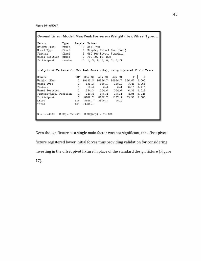
FromtheANOVAinFigure16,theinteractionbetweenthefixtureandwheel
positionissignificant,withap‐valueof0.046.
Page 56
45
Figure 16 ‐ ANOVA
Eventhoughfixtureasasinglemainfactorwasnotsignificant,theoffsetpivot
fixtureregisteredlowerinitialforcesthusprovidingvalidationforconsidering
investingintheoffsetpivotfixtureinplaceofthestandarddesignfixture(Figure
17).
Page 57
46
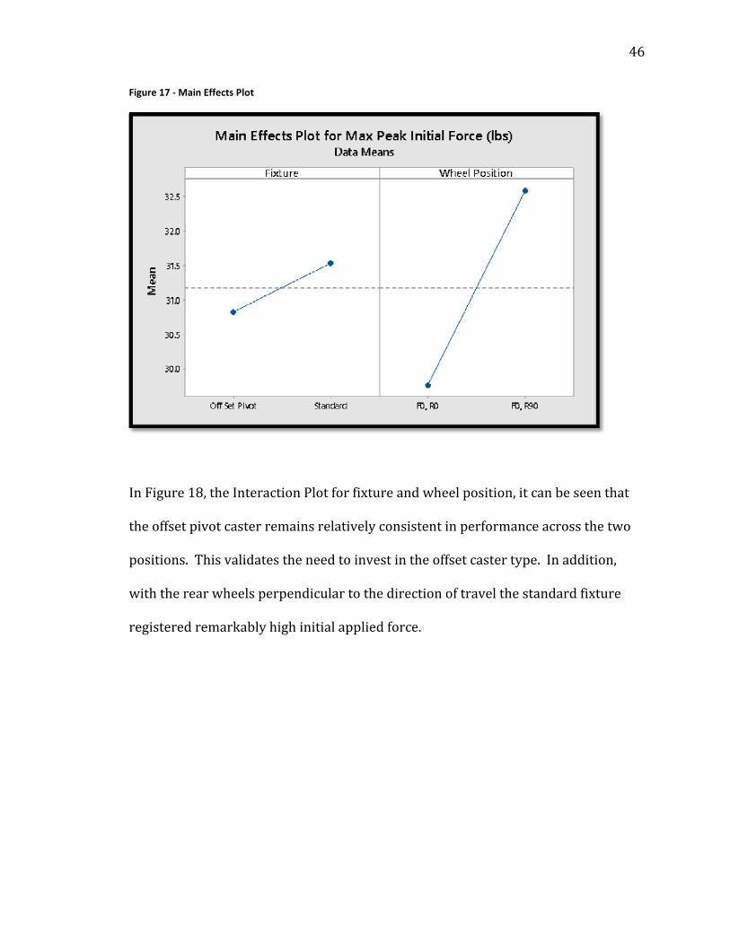
Figure 17 ‐ Main Effects Plot
InFigure18,theInteractionPlotforfixtureandwheelposition,itcanbeseenthat
theoffsetpivotcasterremainsrelativelyconsistentinperformanceacrossthetwo
positions.Thisvalidatestheneedtoinvestintheoffsetcastertype.Inaddition,
withtherearwheelsperpendiculartothedirectionoftravelthestandardfixture
registeredremarkablyhighinitialappliedforce.
Page 58
47
Figure 18 ‐ Interaction Plot
Testforhypothesis3:
Quantifythesignificanceofthethreemainfactors(wheeltype,castertypeand
wheelposition)onthepeakforcerequiredtomoveafourwheeledcart.
Hypothesis3a:Thethreemainfactorswillhaveasignificantinteractive
effectonthepeakforce.
Hypothesis3b:Thethreemainfactorswillnothaveasignificantinteractive
effectonthepeakforce.
Figure19givesasummaryofthe3rdand4thstepsinthelinearmodelbuilding
procedure.Itcanbeobservedthattheinteractionbetweenfixtureandwheeltypeis
notsignificantwithap‐valueof0.142whichisnearthethresholdof0.1.The
interactionbetweenfixtureandwheeltype(Figure21),thoughsignificantisnot
dependentonwheelposition.
Page 59
48
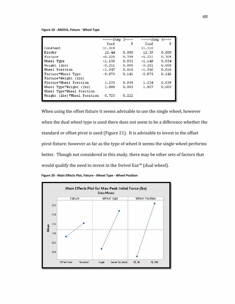
Figure 19 ‐ ANOVA, Fixture ‐ Wheel Type
Whenusingtheoffsetfixtureitseemsadvisabletousethesinglewheel;however
whenthedualwheeltypeisusedtheredoesnotseemtobeadifferencewhetherthe
standardoroffsetpivotisused(Figure21).Itisadvisabletoinvestintheoffset
pivotfixture;howeverasfarasthetypeofwheelitseemsthesinglewheelperforms
better.Thoughnotconsideredinthisstudy,theremaybeothersetsoffactorsthat
wouldqualifytheneedtoinvestintheSwivelEaz™(dualwheel).
Figure 20 ‐ Main Effects Plot, Fixture ‐ Wheel Type ‐ Wheel Position
Page 60
49
Inaddition,theinteractionplotbetweenfixtureandwheeltypeinFigure21shows
thattheinitialpeakforceisreducedmostwhenthesinglewheeltypeis
incorporatedintotheoffsetpivot(SwivelEaz™Pro)fixturewhichkeptinitialforce
nearlyconsistentbetweenthetwowheelpositions.
Figure 21 ‐ Interaction Plot; Fixture ‐ Wheel Type ‐ Wheel Position
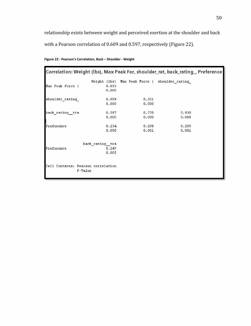
5.4 Psychophysical Analysis of Perceived Exertion Totestthestrengthoftherelationshipsbetweenweight,force,andperceived
exertionontheshouldersandback,aPearson’sCorrelationtestwasused.Itis
evidentfromFigure22thatastrongpositivecorrelationexistsbetweenthesefour
variables.Weightwasaddedasacorrelationfactortovalidatethepositive
correlationbetweentheselfreportedperceivedexertionresponses.Astrong
Page 61
50
relationshipexistsbetweenweightandperceivedexertionattheshoulderandback
withaPearsoncorrelationof0.609and0.597,respectively(Figure22).
Figure 22 ‐ Pearson’s Correlation, Back – Shoulder ‐ Weight
Page 62
51
TheAnderson‐DarlingNormalitytestwasconductedtodetermineiftheperceived
exertiondatawerenormallydistributed.EvidentinFigures23a‐b,bothperceived
exertiondataarenotnormallydistributed.
Figure 23 ‐ Normal Probability, Shoulder and Back
(Figure 23a) (Figure 23b)
ItwasthereforenecessarytotransformthedatausingtheBoxCoxpower
transformationmodelasseenFigures24a‐b.
Figure 24 ‐ Box Cox ‐ Shoulder and Back Data Transformation
(Figure 24a) (Figure 24b)
Forconsistencyofinterpretation,shouldersandbackBorgratingsofperceived
exertionweregivenalogarithmictransformation.Generallinearmodelsusingthe
Page 63
52
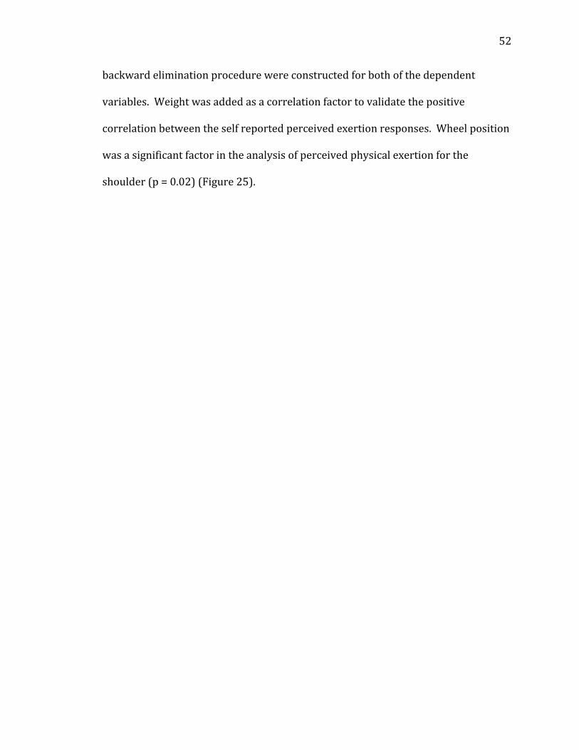
backwardeliminationprocedurewereconstructedforbothofthedependent
variables.Weightwasaddedasacorrelationfactortovalidatethepositive
correlationbetweentheselfreportedperceivedexertionresponses.Wheelposition
wasasignificantfactorintheanalysisofperceivedphysicalexertionforthe
shoulder(p=0.02)(Figure25).
Page 64
53
Figure 25 ‐ ANOVA General Linear Model ‐ Shoulders
Backward Elimination of Terms Candidate terms: Blocks, Fixture, Wheel Type, Weight (lbs), Wheel Position, Fixture*Wheel Type, Fixture*Weight (lbs), Fixture*Wheel Position, Wheel Type*Weight (lbs), Wheel Type*Wheel Position, Weight (lbs)*Wheel Position ------Step 1----- ------Step 2----- Coef P Coef P Constant 0.1946 0.1946 Blocks -0.8011 0.000 -0.8011 0.000 Fixture 0.0313 0.355 0.0313 0.353 Wheel Type -0.0494 0.145 -0.0494 0.143 Weight (lbs) -0.4375 0.000 -0.4375 0.000 Wheel Position -0.0802 0.019 -0.0803 0.018 Fixture*Wheel Type 0.0153 0.651 0.0153 0.649 Fixture*Weight (lbs) -0.0663 0.051 -0.0663 0.050 Fixture*Wheel Position 0.0287 0.396 0.0287 0.392 Wheel Type*Weight (lbs) -0.0252 0.455 -0.0253 0.453 Wheel Type*Wheel Position -0.0303 0.370 -0.0302 0.369 Weight (lbs)*Wheel Position 0.0047 0.888 S 0.376918 0.375219 R-sq 76.92% 76.91% R-sq(adj) 73.28% 73.52% R-sq(pred) 68.61% 69.17% Mallows’ Cp 18.00 16.02 ------Step 3----- ------Step 4----- Coef P Coef P Constant 0.1943 0.1939 Blocks -0.8008 0.000 -0.8004 0.000 Fixture 0.0317 0.346 0.0322 0.336 Wheel Type -0.0491 0.144 -0.0486 0.147 Weight (lbs) -0.4379 0.000 -0.4384 0.000 Wheel Position -0.0803 0.018 -0.0804 0.017 Fixture*Wheel Type Fixture*Weight (lbs) -0.0660 0.050 -0.0655 0.051 Fixture*Wheel Position 0.0287 0.391 0.0287 0.391 Wheel Type*Weight (lbs) -0.0249 0.458 Wheel Type*Wheel Position -0.0302 0.367 -0.0301 0.367 Weight (lbs)*Wheel Position S 0.373867 0.373117 R-sq 76.87% 76.75% R-sq(adj) 73.71% 73.82% R-sq(pred) 69.64% 70.05% Mallows’ Cp 14.23 12.77
Page 65
54
------Step 5----- ------Step 6----- Coef P Coef P Constant 0.1939 0.1939 Blocks -0.8004 0.000 -0.8004 0.000 Fixture 0.0323 0.335 0.0323 0.333 Wheel Type -0.0486 0.146 -0.0486 0.146 Weight (lbs) -0.4385 0.000 -0.4386 0.000 Wheel Position -0.0799 0.018 -0.0804 0.017 Fixture*Wheel Type Fixture*Weight (lbs) -0.0655 0.051 -0.0655 0.051 Fixture*Wheel Position Wheel Type*Weight (lbs) Wheel Type*Wheel Position -0.0305 0.360 Weight (lbs)*Wheel Position S 0.372687 0.372431 R-sq 76.60% 76.42% R-sq(adj) 73.88% 73.91% R-sq(pred) 70.38% 70.68% Mallows’ Cp 11.50 10.33 ------Step 7----- Coef P Constant 0.1930 Blocks -0.7995 0.000 Fixture 0.0332 0.323 Wheel Type Weight (lbs) -0.4394 0.000 Wheel Position -0.0804 0.017 Fixture*Wheel Type Fixture*Weight (lbs) -0.0647 0.055 Fixture*Wheel Position Wheel Type*Weight (lbs) Wheel Type*Wheel Position Weight (lbs)*Wheel Position S 0.374295 R-sq 75.97% R-sq(adj) 73.65% R-sq(pred) 70.64% Mallows’ Cp 10.42 α to remove = 0.1
Page 66
55
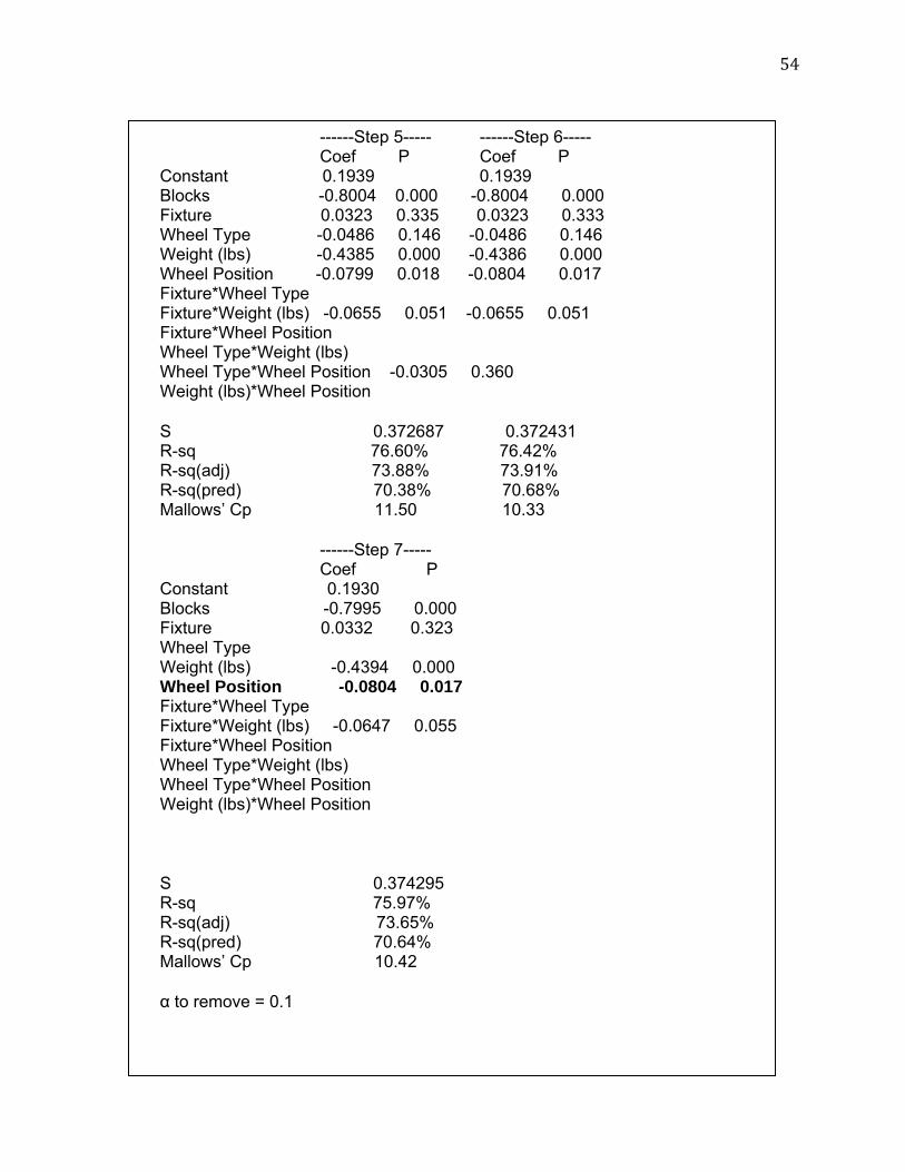
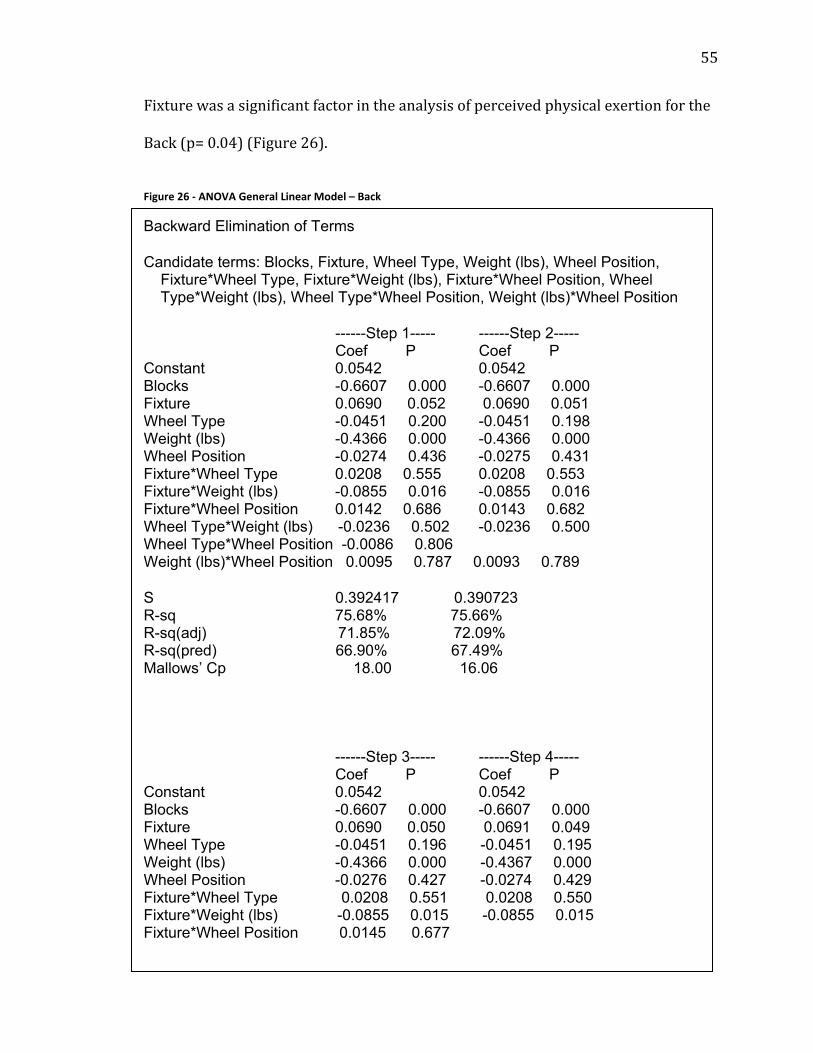
Fixturewasasignificantfactorintheanalysisofperceivedphysicalexertionforthe
Back(p=0.04)(Figure26).
Figure 26 ‐ ANOVA General Linear Model – Back
Backward Elimination of Terms Candidate terms: Blocks, Fixture, Wheel Type, Weight (lbs), Wheel Position, Fixture*Wheel Type, Fixture*Weight (lbs), Fixture*Wheel Position, Wheel Type*Weight (lbs), Wheel Type*Wheel Position, Weight (lbs)*Wheel Position ------Step 1----- ------Step 2----- Coef P Coef P Constant 0.0542 0.0542 Blocks -0.6607 0.000 -0.6607 0.000 Fixture 0.0690 0.052 0.0690 0.051 Wheel Type -0.0451 0.200 -0.0451 0.198 Weight (lbs) -0.4366 0.000 -0.4366 0.000 Wheel Position -0.0274 0.436 -0.0275 0.431 Fixture*Wheel Type 0.0208 0.555 0.0208 0.553 Fixture*Weight (lbs) -0.0855 0.016 -0.0855 0.016 Fixture*Wheel Position 0.0142 0.686 0.0143 0.682 Wheel Type*Weight (lbs) -0.0236 0.502 -0.0236 0.500 Wheel Type*Wheel Position -0.0086 0.806 Weight (lbs)*Wheel Position 0.0095 0.787 0.0093 0.789 S 0.392417 0.390723 R-sq 75.68% 75.66% R-sq(adj) 71.85% 72.09% R-sq(pred) 66.90% 67.49% Mallows’ Cp 18.00 16.06
------Step 3----- ------Step 4----- Coef P Coef P Constant 0.0542 0.0542 Blocks -0.6607 0.000 -0.6607 0.000 Fixture 0.0690 0.050 0.0691 0.049 Wheel Type -0.0451 0.196 -0.0451 0.195 Weight (lbs) -0.4366 0.000 -0.4367 0.000 Wheel Position -0.0276 0.427 -0.0274 0.429 Fixture*Wheel Type 0.0208 0.551 0.0208 0.550 Fixture*Weight (lbs) -0.0855 0.015 -0.0855 0.015 Fixture*Wheel Position 0.0145 0.677
Page 67
56
Wheel Type*Weight (lbs) -0.0236 0.498 -0.0236 0.497 Wheel Type*Wheel Position Weight (lbs)*Wheel Position S 0.389071 0.387620 R-sq 75.65% 75.61% R-sq(adj) 72.33% 72.53% R-sq(pred) 68.04% 68.58% Mallows’ Cp 14.13 12.30 ------Step 5----- ------Step 6----- Coef P Coef P Constant 0.0538 0.0534 Blocks -0.6603 0.000 -0.6599 0.000 Fixture 0.0695 0.047 0.0700 0.044 Wheel Type -0.0447 0.197 -0.0443 0.200 Weight (lbs) -0.4371 0.000 -0.4376 0.000 Wheel Position -0.0275 0.427 -0.0275 0.425 Fixture*Wheel Type Fixture*Weight (lbs) -0.0851 0.015 -0.0847 0.015 Fixture*Wheel Position Wheel Type*Weight (lbs) -0.0231 0.505 Wheel Type*Wheel Position Weight (lbs)*Wheel Position S 0.386509 0.385564 R-sq 75.53% 75.43% R-sq(adj) 72.69% 72.82% R-sq(pred) 69.02% 69.44% Mallows’ Cp 10.65 9.09
------Step 7----- ------Step 8----- Coef P Coef P Constant 0.0534 0.0526 Blocks -0.6599 0.000 -0.6591 0.000 Fixture 0.0700 0.044 0.0708 0.042 Wheel Type -0.0443 0.199 Weight (lbs) -0.4376 0.000 -0.4384 0.000 Wheel Position Fixture*Wheel Type Fixture*Weight (lbs) -0.0847 0.015 -0.0839 0.016 Fixture*Wheel Position Wheel Type*Weight (lbs) Wheel Type*Wheel Position Weight (lbs)*Wheel Position S 0.384958 0.386073
Page 68
57
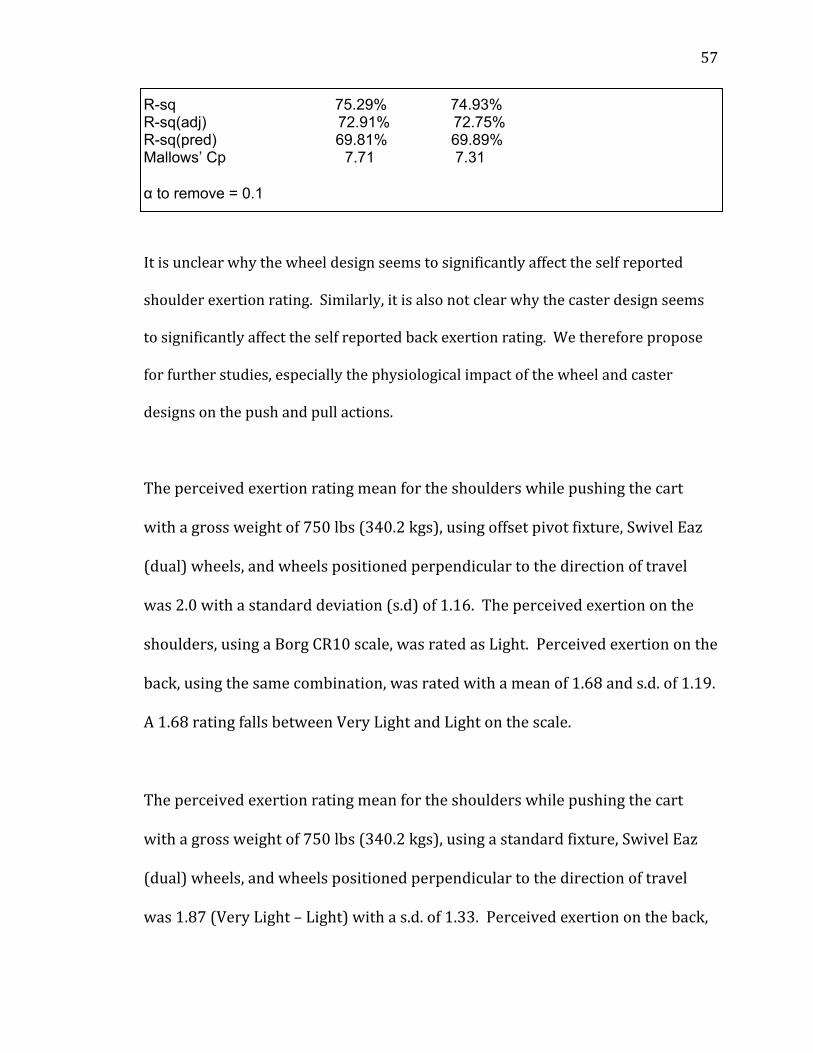
R-sq 75.29% 74.93% R-sq(adj) 72.91% 72.75% R-sq(pred) 69.81% 69.89% Mallows’ Cp 7.71 7.31 α to remove = 0.1
Itisunclearwhythewheeldesignseemstosignificantlyaffecttheselfreported
shoulderexertionrating.Similarly,itisalsonotclearwhythecasterdesignseems
tosignificantlyaffecttheselfreportedbackexertionrating.Wethereforepropose
forfurtherstudies,especiallythephysiologicalimpactofthewheelandcaster
designsonthepushandpullactions.
Theperceivedexertionratingmeanfortheshoulderswhilepushingthecart
withagrossweightof750lbs(340.2kgs),usingoffsetpivotfixture,SwivelEaz
(dual)wheels,andwheelspositionedperpendiculartothedirectionoftravel
was2.0withastandarddeviation(s.d)of1.16.Theperceivedexertiononthe
shoulders,usingaBorgCR10scale,wasratedasLight.Perceivedexertiononthe
back,usingthesamecombination,wasratedwithameanof1.68ands.d.of1.19.
A1.68ratingfallsbetweenVeryLightandLightonthescale.
Theperceivedexertionratingmeanfortheshoulderswhilepushingthecart
withagrossweightof750lbs(340.2kgs),usingastandardfixture,SwivelEaz
(dual)wheels,andwheelspositionedperpendiculartothedirectionoftravel
was1.87(VeryLight–Light)withas.d.of1.33.Perceivedexertionontheback,
Page 69
58
usingthesamecombination,hadaratingmeanof1.62(VeryLight–Light)and
s.d.of1.41.Allofthecombinationsandtheirperceivedexertionscanbefoundin
AppendixC.
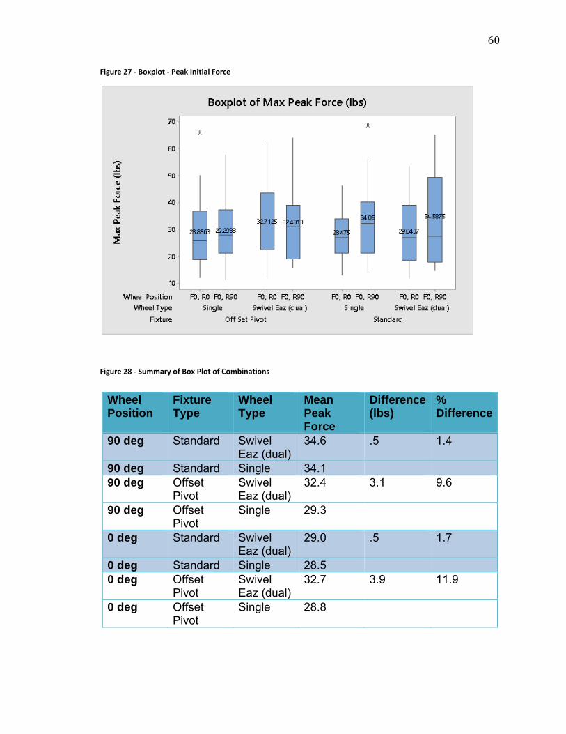
Thestandardfixturewithasinglewheelpositionedperpendiculartothe
directionoftravelwith750lbs(340.2kgs)wasactuallyratedlowestwhen
comparedtotheothertwowheel‐fixturecombinations.Thisisattributedto
thestatisticallysignificantinteractionbetweenthewheeltypeandthecaster
design,wheretheleastinitialpushforcewasrequiredwhenusingacartwiththe
singlewheelandoffsetpivotcastercombination.Thisclaimissupportedbythe
datasummaryinFigures27and28.
Chapter 6: Discussion
Thepurposeofthisresearchwastoinvestigatetheeffectsofwheelandfixture
designsonpushingforceofafour‐wheeledcart.Thefollowingdiscussionisa
reviewofthehypothesisandthepracticaleffectivenessandapplication.
6.1 Hypothesis Discussion Split‐wheeldesignwilleffecttheinitialappliedpeakforcerequiredtomovea
fourwheeledcart.
Page 70
59
Whenthewheelswerepositionedperpendicularwithdirectionoftravel(F0R90)
andtheSwivelEaz™dualwheelwasusedinthestandardfixture,thepeakapplied
forcemeanwas34.6lbsandwas1.4%greaterthanthepeakappliedforcemeanof
34.1lbsattainedwhenthesinglewheelwasusedinthesamestandardfixture.
Takingintoaccountpossiblestatisticalerror,thedifferenceof1.4%maynotbe
significantenoughtodifferentiateonewheelasabetteroptionovertheother
(Figures27–28).
Page 71
60
Figure 27 ‐ Boxplot ‐ Peak Initial Force
Figure 28 ‐ Summary of Box Plot of Combinations
Wheel Position
Fixture Type
Wheel Type
Mean Peak Force
Difference (lbs)
% Difference
90 deg Standard Swivel Eaz (dual)
34.6 .5 1.4
90 deg Standard Single 34.1 90 deg Offset
Pivot Swivel Eaz (dual)
32.4 3.1 9.6
90 deg Offset Pivot
Single 29.3
0 deg Standard Swivel Eaz (dual)
29.0 .5 1.7
0 deg Standard Single 28.5 0 deg Offset
Pivot Swivel Eaz (dual)
32.7 3.9 11.9
0 deg Offset Pivot
Single 28.8
Page 72
61
Whenthewheelswerepositionedinlinetothedirectionoftravel(F0R0)andthe
SwivelEaz™dualwheelwasusedinthestandardfixture,thepeakappliedforce
meanwas34.1lbs(15.5kgs)andwas1.7%greaterthanthepeakappliedforce
meanof28.5lbs(12.9kgs)attainedwhenthesinglewheelwasusedinthesame
standardfixture.Again,thedifferencebetweenthetwocombinationsmaynotbe
significantenoughtodifferentiateonewheelovertheotherasabetteroption
(Figures27–28).
The“offsetpivot”castermountingwilleffecttheinitialpeakappliedforce
requiredtomoveafourwheeledcart.
Whenthesinglewheelswerepositionedperpendiculartothedirectionoftravel
(F0R90)andusedwiththeoffsetpivot(SwivelEaz™Pro)fixturetheappliedpeak
forcemeanwas29.3lbs(13.3kgs).Thiswas16.4%lowerthantheappliedpeak
forcemeanof29.3lbs(13.3kgs)whichwasattainedwhenasinglewheelwasused
inastandardfixtureandalsopositionedperpendiculartothedirectionoftravel.In
otherwords,whentherearwheelswerepositionedat90degreestothedirectionof
travel,offsetpivotfixture(caster)had16.4%lowerappliedpeakforcemeanversus
thesinglewheelinthestandardfixture.
Quantifythesignificanceofthethreemainfactors(wheeltype,castertypeand
wheelposition)onthepeakforcerequiredtomoveafourwheeledcart.
Page 73
62
Whenusingtheoffsetfixtureitseemsadvisabletousethesinglewheel;however
whenthedualwheeltypeisusedtheredoesnotseemtobeadifferencewhether
standardoroffsetpivotisused.Itseamsadvisabletoinvestintheoffsetpivot
fixture;howeverasfarasthetypeofwheelitseemsthesinglewheelperforms
betterinthisparticularapplication.Thoughnotconsideredinthisstudy,theremay
beothersetsoffactorsthatwouldqualifytheneedtoinvestintheSwivelEaz™
(dualwheel).Forexample,thisstudydidnotconsiderwheelsurfacedurabilityor
wheelbearingwearovertime.
6.2 Variability Between Subjects Therewasvariationinthepeakforcerangesbetweenthe8differentsubjects.For
example,incombination4whenthegrosscartweightwas250lbs(113.4kgs),rear
wheelswerepositionedatF0R90,SwivelEaz(dual)wheelsweremountedonthe
standardfixture,theminimumpeakappliedforcewas14.3lbs(6.5kgs).The
maximumpeakforceappliedbyaparticipantwas33.2lbs(15.1kgs)thedifference
intherange18.9lbs(8.6kgs)andthestandarddeviationwas6.69lbs(3.0kgs)
(Table5).Incombination12,whenthegrosscartweightwas750lbs(340.2kgs),
rearwheelswerepositionedatF0R90,SwivelEaz(dual)wheelsweremountedon
thestandardfixture,theminimumpeakappliedforcewas27.2lbs(12.3kgs).The
maximumpeakforceappliedbyaparticipantwas65.4lbs(29.7kgs)thedifference
intherangeis38.2lbs(17.3kgs)andthestandarddeviationwas15.41(7.0kgs).
Theoverallrangedifferencesforeachoftherangesineachcombinationvariedfrom
16.5–45.5.
Page 74
63
Table 5 ‐ Applied Peak Force Range
6.3 Perceived Exertion Asexpected,therewasastrongrelationshipbetweentheamountofweightthe
participanthadtopushandtheirlevelofperceivedexertion.Whatremainsunclear
iswhywheeltypewasasignificantfactorinthelevelofperceivedexertionforthe
shoulderandnotwiththeback.Inaddition,itisunclearwhythefixtureisthe
significantfactorinperceivedlevelofexertionintheback.Participantsdidratethe
levelofperceivedexertionslightlyhigheronboththeshoulderandthebackwhen
pushingthe750lb(340.2kgs)cartwiththeoffsetpivot,SwivelEazwheel,and
positionedperpendiculartothedirectionoftravelversusthesamecombinationand
usingthestandardfixture,LightcomparedtoVeryLight‐Light,respectively.
Page 75
64
6.4 Application of the Results/Psychophysical Application Manyoftheforcedifferencesobservedinthisstudyweremodest,andgiventhe
largevariabilitybetweensubjectvariability,itcouldbearguedthatthereareno
practicaldifferencesbetweenanyofthewheel‐fixturecombinations.However,the
offsetpivotfixturecouldbeavaluableinterventioninsomecommonsituations.To
illustratethis,considerthefollowingscenario.
6.4.1 Scenario 1 – Changing Fixtures
Aworkerisrequiredtopushacartfor200feet(61m)twotimesperhourwiththe
handleheightathiplevel.Theinitialforcerequiredtogetthecartintomotion
whenthewheelsareperpendiculartothedirectionoftravelis40lbs(18.1kgs).
Thesustainedforcerequiredtokeepthecartinmotionis19.0lbs.Accordingtothe
SnookandCirellotables[9]‐[32],theinitialforceof40lbs(18.1kgs)isacceptableto
83%ofmalesand66%offemales.TherecommendeddesigngoalfromSnookand
Cirelliowasforthetasktobeacceptableforatleast75%offemales[9]‐[32].
Ifacartdesignerwantedtoreducetheinitialforcewhenthewheelsarepositioned
perpendiculartothedirectionoftravel,theycouldinstallasetofoffsetpivot
(SwivelEaz™Pro)fixtureswithsinglewheels.Basedonresultsfromthisstudy,and
ifallothervariableswereequal,theappliedpeakforcemeanwouldbeloweredby
16.1%.Inotherwords,thepeakforceof40lbs(18.1kgs)wouldbeloweredto33.6
lbs(15.2kgs).Thiswouldnowmakethejobacceptableto84%ofthefemalesand
90%ofthemales[9]‐[32].Itthiscaseitseemsadvisabletoimplementtheoffset
pivotfixturewiththesinglewheel.
Page 76
65
6.5 Limitations of the Study
6.5.1 Instantaneous Peak Force
Although,forcedatawasrecordedfromwhenthecartstartedmotionuntilafterit
stopped,thisstudyonlyfocusedonthepeakappliedinstantaneousforce.Thereisa
possibilitythatthetenthofaseconddatapointwasnotrepresentativeoftheactual
averageinitialforce.Themedianforceoverthebriefinitialperiodmaybeabetter
representationofinitialforce.Henceforfutureanalysisinthisstudy,averageinitial
forceinadditiontothesustainedpushforceswillbeusedasopposedtoinitialpeak
force.
6.5.2 Lateral Force
Lateralforcewasrecordedduringthestudybutitwasnotafocusforthisthesis.It
seemsreasonabletoexpectthattheoffsetpivotfixturewouldsignificantlyreduce
lateralmovementwhenthecartisinitiallystarted,especiallywhenthewheelsare
positionedat90degreesorotherwiseoutofalignment.
6.6 Contribution to the Body of Knowledge Theimpactofthisstudyistointroducedataandstatisticalanalysisofanewstyleof
wheelandfixtureofwhichnopublishedstudieswerefound.Thestudy
demonstratedthatifanorganizationislookingtoreduceinitialforcewhenwheels
aremisalignedwiththedirectionoftraveltheoffsetpivot(SwivelEaz™Pro)isa
viablealternative.
Page 77
66
6.7 Future Studies FurtherstudycouldbeconductedontheSwivelEaz™wheelstounderstandhow
theyperformafterbeingin‐useforanextendedperiodoftime.Thewheelsand
fixturesusedwerenewatthestartofthestudy.Thewheelscouldalsobetested
overroughsurfacesasitseemsreasonabletoexpecttheSwivelEaz™dualwheels
toperformbetteroversurfacesthatarenotflat.Asmentionedearlier,futurestudy
andanalysiscouldlookattheaverageinitialforce,thesustainedforce,andlateral
force.
Chapter 7: Conclusion
Thesponsorsoughttoinvestigatetheeffectsofthewheelandfixture(caster)
designsonpushingforceofafour‐wheeledcart.Basedonthestudyfindingsand
resultsfromthisanalysisthefollowingrecommendationsarebeingmadetothe
sponsor:
1) Iflookingtoreducepushforcewhenthewheelsarepositioned
perpendiculartothedirectionoftravel,considerutilizingtheSwivel
Eaz™Profixturewiththesinglewheel;however,thecostoftheSwivel
Eaz™Profixturemaynotbejustifiabletoonlygaina16%reductionin
force.
2) Otherfactorsshouldbeconsideredwhendecidingwhethertopurchase
theSwivelEaz™ProfixtureandSwivelEaz™dualwheelssuchas
Page 78
67
longevityunderruggedconditionsandwhetherthewheelscantraverse
bumpsorunevensurfacesmoreeasily.
3) Duringthestudy,differencesintheparticipant’sperceivedexertion
ratingsmeansseemednearlyinconsequentialastheratingsfor750lbs
(340.2kgs)rangedfrom1.38–2.00whichfallsbetween“VeryLight–
Light”fortheshouldersand1.19–1.81“VeryLight–Light”fortheback.
Inotherwords,thedifferencesinfixtureandwheeltypewereeffectively
imperceptibletotheparticipant.
Page 79
68
References 1. A.Gargetal.,“Psychophysicalbasisformaximumpushingandpullingforces:A
reviewandrecommendations,”Int.J.ofInd.Ergonom.,vol.44,pp.281‐291,2014.
2. S.Konz,“NIOSHliftingguidelines,”Am.Ind.Hyg.Assoc.J.,vol.43,Iss.12,1982.
3. K.P.GranataandB.C.Bennett,“Low‐backbiomechanicsandstaticstabilityduringisometricpushing,”HumanFactors,”vol.47,no.3,pp.536‐549,Fall2005.
4. LibertyMutualResearchInstituteforSafety,(2013)2013Libertymutualworkplacesafetyindex(Online).Available:http://www.libertymutualgroup.com/omapps/ContentServer?pagename=LMGroup/Views/LMG&ft=2&fid=1138356633468&ln=en
5. K.K.LettandS.M.McGill,“Pushingandpulling:personalmechanicsinfluence
spineloads,”Ergonom.,vol.49,no.9,pp.895‐908,July2006.
6. Ohio‐Bureauofworkers’compensation,(2014)Whatismanualmaterialshandling?(Online).Available:https://www.bwc.ohio.gov/downloads/.../MaterialsHandling.pdf
7. TexasDepartmentofInsurance,(2014)Manualmaterialhandling–Anergonomicapproach(Online).Available:http://www.tdi.texas.gov/pubs/videoresource/wpmanmathand.pdf
8. M.P.Loozeetal.,“Forcedirectionandphysicalloadindynamicpushingandpulling,”Ergonom.,vol.43,pp.377‐390,2000.
9. S.H.SnookandV.M.Ciriello,“Thedesignofmanualhandlingtasks:revisedtables
ofacceptableweightsandforces,”Ergonom.,vol.34,pp.1197‐1213,1991.10. K.W.Al‐Eisawietal.,“Factorsaffectingminimumpushandpullforcesofmanual
carts,”Appl.Ergonom.vol30,pp.235‐245,1999.11. K.W.Al‐Eisawiet.Al.,“Theeffectofhandleheightandcartloadontheinitialhand
forcesincartpushingandpulling,”Ergonom.,vol.42,no.8,pp.1099‐1113,1999.12. T.Brace,“Thedynamicsofpushingandpullingintheworkplace,”J.oftheAmer.
Assoc.ofOccupat.HealthNurses.Vol53,pp.224‐229,2005.13. EastmanKodakCo.,Kodak’sErgonomicDesignforPeopleatWork.vol2,
Hoboken,NJ:JohnWileyandSons,Inc.,2004.
Page 80
69
14. M.C.Jungetal.,“Pushingandpullingcartsandtwo‐wheeledhandtrucks,”Int.J.ofInd.Ergonom.,vol.35,pp.79‐89,2005.
15. V.M.Cirielloetal.,“Distributionsofmaterialshandlingtaskparameters,”Int.J.ofInd.Ergonom.,vol.24,pp.379‐388,1999.
16. M.L.Resnick,“Kinematics,kinetics,andpsychophysicalperceptionsinsymmetric
andtwistingpushingandpullingtasks,”HumanFactors,vol.38,no.1,pp.114‐129,1996.
17. D.B.Chaffinetal.,OccupationalBiomechanics,3rded.,NewYork,NY:JohnWiley
andSons,Inc.,1999.18. AubinInd,(2014,May2)SwivelEaz[Online].Available:
http://www.aubinindustries.com/products/swivel‐eaz/
19. P.A.Aubin,“Independentlyrotatable,splittread,singlewheelassembly,”U.S.Patent6880203B1,April19,2005.
20. P.A.Aubin,“Casterwithdualoffsetorbitalmountingassembly,”U.S.Patent8
387209B2,March5,2013.21. OshkoshCorporation,(2014,November3)CompanyProfile[Online].Available:
http://www.oshkoshcorporation.com/about/company_profile.html22. G.Borg,“TheBorgCR10Scale,”Borg’sPerceivedExertionandPainScales.,
Champaign,IL:HumanKinetics,1998.23. A.Zamuner,etal.,“AssessmentofSubjectivePerceivedExertionattheAnaerobic
ThresholdwiththeBorgCR‐10Scale”,JournalofSportsScienceMedicine,Vol.10pp.130‐136,2011.
24. HenryDreyfusAssociates,TheMeasureofManandWoman,reviseded.New
York,NY:JohnWileyandSons,Inc.,2002.25. OSHA,01/20/1999,OSHATechnicalManual(OTM)SectionVII:Chapter1,
[Online].Available:https://www.osha.gov/dts/osta/otm/otm_vii/otm_vii_1.html
26. P.G.Hewitt,ConceptualPhysics,9thEd.,SanFrancisco,CA:AddisonWesley,2002.27. D.Lippert,J.Spektor.“Calculatingproperrollingresistance:Asafermovefor
materialhandling.”Internet:http://www.plantengineering.com/single‐article/calculating‐proper‐rolling‐resistance‐a‐safer‐move‐for‐material‐handling/82fa156f91ea516c6b08be3bc595db65.html,Oct.5,2012[Nov.10,2014].
Page 81
70
28. E.A.Avalloneetal.,“Friction”inMarksStandardHandbookforMechanical
Engineers,11thEdition.E.A.Avalloneetal.,NewYork:McGraw‐Hill,2007,pp.3‐20‐3‐29.
29. DarcorCastersandWheels,(2014,November14)CasterInfoandGlossaryof
Terms[Online].Available:http://www.darcor.com/technical/caster‐info/30. TheMinitabblog,(2014,November16)NoMatterHowStrong,Correlation
Doesn’tImplyCausation(Online).http://blog.minitab.com/blog/understanding‐statistics/no‐matter‐how‐strong‐correlation‐still‐doesnt‐imply‐causation
31. TheMinitabblog,(2012,June12)UsingStepwiseRegressiontoExplainPlant
EnergyUsage(Online).http://blog.minitab.com/blog/real‐world‐quality‐improvement/using‐minitab‐stepwise‐regression‐to‐explain‐plant‐energy‐usage
32. ThomasE.Bernard‐Ergonomics,(2014,November25)LibertyMutualManual
MaterialsHandlingTables(Online).http://personal.health.usf.edu/tbernard/ergotools/
Page 83
72
Appendix A – Pre Screening Form
Pre – Screening Form
Date: Age: Gender: Male Female Height: Weight:
1) Are you currently experiencing any back or shoulder pain? YES NO
a. If you answered YES to question 1 then you are not allowed to participate in the study.
b. If you answered NO then continue to question 2…
2) Have you had any back or shoulder pain lasting more than 24 hours in the past 12 months ? YES NO
a. If you answered YES to question 2, do you feel this pain will prohibit you from safely completing the task? YES NO
i. If you answered YES to question 2a and feel the pain will prohibit you from safely completing the study then you are not allowed to participate in the study.
3) If you answered NO to question 2 then you are allowed to participate in
the study. Thank you for assistance in this project.
4) If you are under the care of a physician and have restrictions regarding pushing, pulling, or other material handling tasks then you are not allowed to participate.
If you have any questions regarding this study, please contact the researcher David Wein at 920-216-3598 or [email protected] . Thank you.
Page 84
73
Appendix B – Participant Information
Page 85
74
Appendix C – Pain and Exertion Rating