32
The EGS Soultz power plant
The EGS Soultz power plant
2
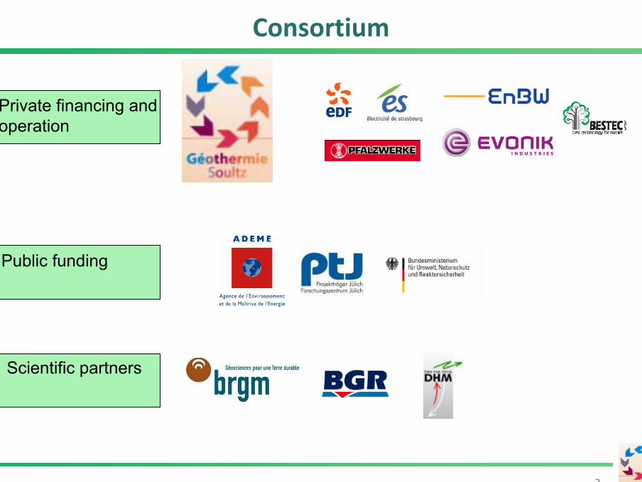
Consortium
Private financing and operation
Public funding
Scientific partners

Our aim: Geothermal Production of Electricity
CreekplantGeysers, USA, 130 MWel
Nesjavellir, Island, 30 MWel
Prince PieroGinori Conti in Lardarello, Italien, at 1904: some light bulbs
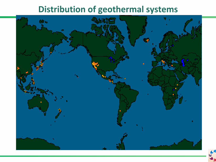
Distribution of geothermal systems

Geothermal Systems consist of:
A heatsource
a permeable network of fissures
a heat transport medium, thermal water
Geothermal Systems
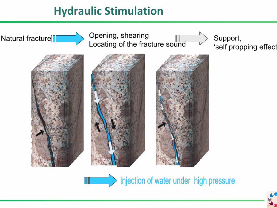
Natural fracture Support, ‘self propping effect’
Opening, shearingLocating of the fracture sound
Hydraulic Stimulation

The concept
600 m 600 m 200°C at 5000 m
GPK2 GPK3 GPK4
Geophone
Observation well
Sediments
Graniticbasement
1.5 MWe (+x MWe)
Dep
th [
m]30 l/s 30 l/s
Construction of a scientific and experimental pilot plant for geothermal power productionfrom crystalline formations.Large-scale permeability improvement by hydraulic stimulation.
7
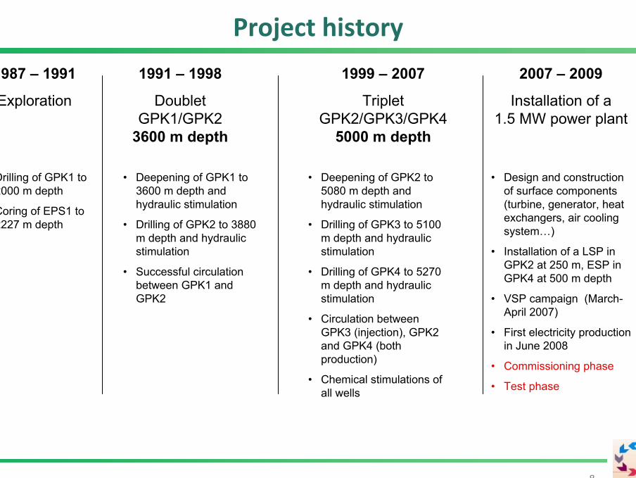
2007 – 2009
Installation of a 1.5 MW power plant
• Design and construction of surface components (turbine, generator, heat exchangers, air cooling system…)
• Installation of a LSP in GPK2 at 250 m, ESP in GPK4 at 500 m depth
• VSP campaign (March-April 2007)
• First electricity production in June 2008
• Commissioning phase
• Test phase
1987 – 1991
Exploration
1991 – 1998
Doublet GPK1/GPK2
3600 m depth
1999 – 2007
Triplet GPK2/GPK3/GPK4
5000 m depth
• Drilling of GPK1 to 2000 m depth
• Coring of EPS1 to 2227 m depth
• Deepening of GPK1 to 3600 m depth and hydraulic stimulation
• Drilling of GPK2 to 3880 m depth and hydraulic stimulation
• Successful circulation between GPK1 and GPK2
• Deepening of GPK2 to 5080 m depth and hydraulic stimulation
• Drilling of GPK3 to 5100 m depth and hydraulic stimulation
• Drilling of GPK4 to 5270 m depth and hydraulic stimulation
• Circulation between GPK3 (injection), GPK2 and GPK4 (both production)
• Chemical stimulations of all wells
Project history
8
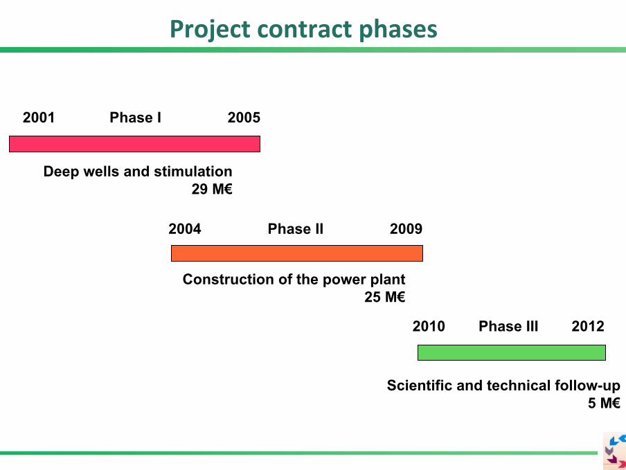
Project contract phases
Deep wells and stimulation29 M€
2001 Phase I 2005
2004 Phase II 2009
Construction of the power plant25 M€
2010 Phase III 2012
Scientific and technical follow-up5 M€

Project design and exploration phase
1010
-> Fractures with hydrothermal alteration, hints on geothermal system
-> Brine with 100 g TDS/l
Temperature profiles
Dep
th[m
]
Temperature [°C]
1987 – 1991
Exploration
• Drilling of GPK1 to 2000 m depth
• Coring of EPS1 to 2227 m depth

‚Upper reservoir‘
11
(Gérard et al., 2006)
Circulation in 1997
First circulation in a closed loop!
- 4 months
- 140 °C
- 10 MWth
- produced fluid contains 70 % brine, increasing salinity during circulation
- no significant seismicity during circulation and stimulation
11
1991 – 1998
Doublet GPK1/GPK2
3600 m depth
• Deepening of GPK1 to 3600 m depth and hydraulic stimulation
• Drilling of GPK2 to 3880 m depth and hydraulic stimulation
• Successful circulation between GPK1 and GPK2
12
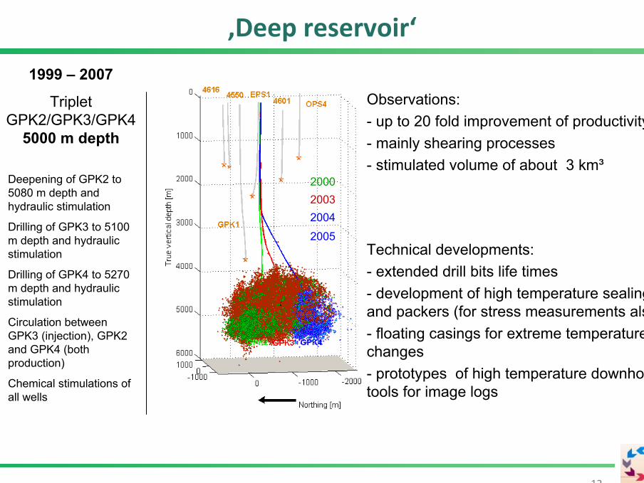
200020032004
2005
Observations:- up to 20 fold improvement of productivity- mainly shearing processes- stimulated volume of about 3 km³
‚Deep reservoir‘
Technical developments:- extended drill bits life times- development of high temperature sealingsand packers (for stress measurements also)- floating casings for extreme temperaturechanges- prototypes of high temperature downhole tools for image logs
1999 – 2007
Triplet GPK2/GPK3/GPK4
5000 m depth
• Deepening of GPK2 to 5080 m depth and hydraulic stimulation
• Drilling of GPK3 to 5100 m depth and hydraulic stimulation
• Drilling of GPK4 to 5270 m depth and hydraulic stimulation
• Circulation between GPK3 (injection), GPK2 and GPK4 (both production)
• Chemical stimulations of all wells
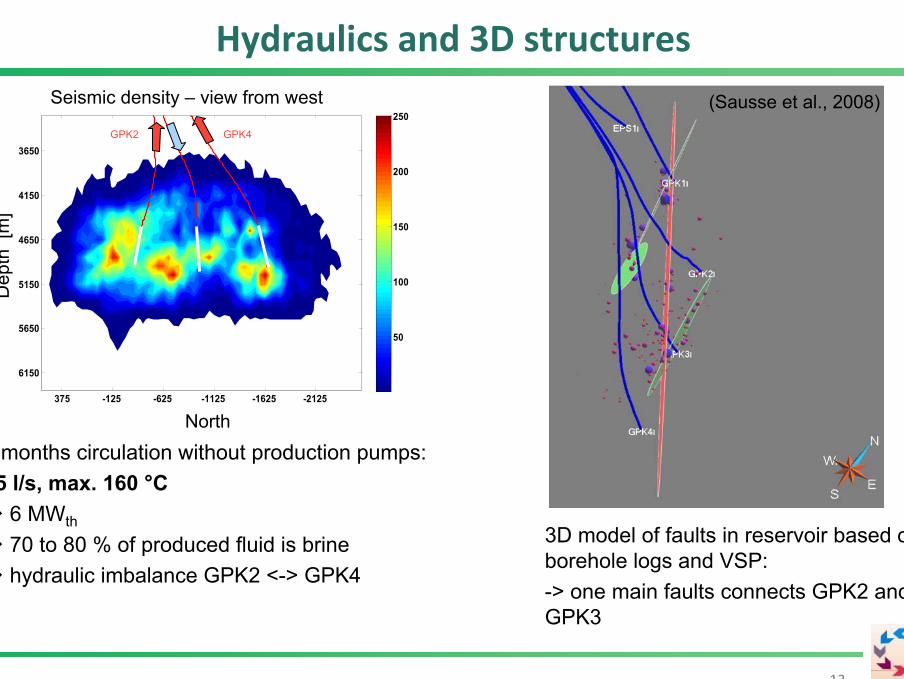
Hydraulics and 3D structures
13
5 months circulation without production pumps:15 l/s, max. 160 °C
6 MWth
70 to 80 % of produced fluid is brinehydraulic imbalance GPK2 <-> GPK4
GPK4GPK2
(Sausse et al., 2008)
3D model of faults in reservoir based on borehole logs and VSP:-> one main faults connects GPK2 and GPK3
side view from west
north
dept
h
-2125-1625-1125-625-125375
3650
4150
4650
5150
5650
6150
50
100
150
200
250Seismic density – view from west
Dep
th[m
]
North
GPK4GPK2
GPK-3
574 m
Drill 24"
GPK-3
20" Casing 133 lbs./ft. X-56 BTC
574 m
Drill 24"
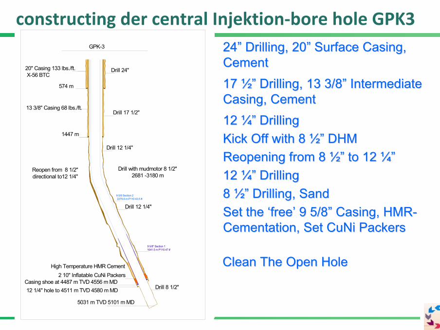
2424”” Drilling, 20Drilling, 20”” Surface Casing, Surface Casing, CementCement
GPK-3
20" Casing 133 lbs./ft. X-56 BTC
574 m
Drill 24"
GPK-3
1447 m
20" Casing 133 lbs./ft. X-56 BTC
574 m
Drill 24"
Drill 17 1/2"
GPK-3
1447 m
20" Casing 133 lbs./ft. X-56 BTC
13 3/8" Casing 68 lbs./ft.
574 m
Drill 24"
Drill 17 1/2"
17 17 ½”½” Drilling, 13 3/8Drilling, 13 3/8”” Intermediate Intermediate Casing, CementCasing, Cement
GPK-3
1447 m
20" Casing 133 lbs./ft. X-56 BTC
13 3/8" Casing 68 lbs./ft.
574 m
Drill 24"
Drill 17 1/2"
12 12 ¼”¼” DrillingDrilling
12 1/4" hole to 4511 m TVD 4580 m MD
GPK-3
1447 m
20" Casing 133 lbs./ft. X-56 BTC
13 3/8" Casing 68 lbs./ft.
574 m
Drill 24"
Drill 17 1/2"
Drill 12 1/4" Kick Off with 8 Kick Off with 8 ½”½” DHMDHM
12 1/4" hole to 4511 m TVD 4580 m MD
GPK-3
1447 m
20" Casing 133 lbs./ft. X-56 BTC
13 3/8" Casing 68 lbs./ft.
574 m
Drill 24"
Drill 17 1/2"
Drill 12 1/4"
Drill with mudmotor 8 1/2" 2681 -3180 m
Reopening from 8 Reopening from 8 ½”½” to 12 to 12 ¼”¼”Drill with mudmotor 8 1/2"
2681 -3180 m
12 1/4" hole to 4511 m TVD 4580 m MD
GPK-3
1447 m
20" Casing 133 lbs./ft. X-56 BTC
13 3/8" Casing 68 lbs./ft.
574 m
Drill 24"
Drill 17 1/2"
Drill 12 1/4"
Reopen from 8 1/2"directional to12 1/4" 12 12 ¼”¼” DrillingDrilling
Drill with mudmotor 8 1/2" 2681 -3180 m
12 1/4" hole to 4511 m TVD 4580 m MD
GPK-3
1447 m
20" Casing 133 lbs./ft. X-56 BTC
13 3/8" Casing 68 lbs./ft.
574 m
Drill 24"
Drill 17 1/2"
Drill 12 1/4"
Drill 12 1/4"
Reopen from 8 1/2"directional to12 1/4"
Drill with mudmotor 8 1/2" 2681 -3180 m
12 1/4" hole to 4511 m TVD 4580 m MD
GPK-3
1447 m
20" Casing 133 lbs./ft. X-56 BTC
13 3/8" Casing 68 lbs./ft.
574 m
Drill 24"
Drill 17 1/2"
5031 m TVD 5101 m MD
Drill 12 1/4"
Drill 8 1/2"
Drill 12 1/4"
Reopen from 8 1/2"directional to12 1/4"
8 8 ½”½” Drilling, SandDrilling, Sand
Drill with mudmotor 8 1/2" 2681 -3180 m
12 1/4" hole to 4511 m TVD 4580 m MD
GPK-3
1447 m
20" Casing 133 lbs./ft. X-56 BTC
13 3/8" Casing 68 lbs./ft.
574 m
Drill 24"
Drill 17 1/2"
5031 m TVD 5101 m MD
Drill 12 1/4"
Drill 8 1/2"
Drill 12 1/4"
Reopen from 8 1/2"directional to12 1/4"
9 5/8 Section 2 2279.6 m P110 43.5 #
Drill with mudmotor 8 1/2" 2681 -3180 m
9 5/8" Section 1 1041.5 m P110 47 #
12 1/4" hole to 4511 m TVD 4580 m MD
GPK-3
1447 m
20" Casing 133 lbs./ft. X-56 BTC
13 3/8" Casing 68 lbs./ft.
574 m
Drill 24"
Drill 17 1/2"
5031 m TVD 5101 m MD
Drill 12 1/4"
Drill 8 1/2" Casing shoe at 4487 m TVD 4556 m MD
Drill 12 1/4"
Reopen from 8 1/2"directional to12 1/4"
9 5/8 Section 2 2279.6 m P110 43.5 #
Drill with mudmotor 8 1/2" 2681 -3180 m
9 5/8" Section 1 1041.5 m P110 47 #
12 1/4" hole to 4511 m TVD 4580 m MD
GPK-3
1447 m
20" Casing 133 lbs./ft. X-56 BTC
13 3/8" Casing 68 lbs./ft.
574 m
Drill 24"
Drill 17 1/2"
5031 m TVD 5101 m MD
Drill 12 1/4"
Drill 8 1/2" Casing shoe at 4487 m TVD 4556 m MD
High Temperature HMR Cement
Drill 12 1/4"
Reopen from 8 1/2"directional to12 1/4"
Set the Set the ‘‘freefree’’ 9 5/89 5/8”” Casing, HMRCasing, HMR--Cementation, Set Cementation, Set CuNiCuNi PackersPackers
9 5/8 Section 2 2279.6 m P110 43.5 #
Drill with mudmotor 8 1/2" 2681 -3180 m
9 5/8" Section 1 1041.5 m P110 47 #
12 1/4" hole to 4511 m TVD 4580 m MD
GPK-3
2 10" Inflatable CuNi Packers
1447 m
20" Casing 133 lbs./ft. X-56 BTC
13 3/8" Casing 68 lbs./ft.
574 m
Drill 24"
Drill 17 1/2"
5031 m TVD 5101 m MD
Drill 12 1/4"
Drill 8 1/2" Casing shoe at 4487 m TVD 4556 m MD
High Temperature HMR Cement
Drill 12 1/4"
Reopen from 8 1/2"directional to12 1/4"
Clean The Open HoleClean The Open Hole
9 5/8 Section 2 2279.6 m P110 43.5 #
Drill with mudmotor 8 1/2" 2681 -3180 m
9 5/8" Section 1 1041.5 m P110 47 #
12 1/4" hole to 4511 m TVD 4580 m MD
GPK-3
2 10" Inflatable CuNi Packers
1447 m
20" Casing 133 lbs./ft. X-56 BTC
13 3/8" Casing 68 lbs./ft.
574 m
Drill 24"
Drill 17 1/2"
5031 m TVD 5101 m MD
Drill 12 1/4"
Drill 8 1/2" Casing shoe at 4487 m TVD 4556 m MD
High Temperature HMR Cement
Drill 12 1/4"
Reopen from 8 1/2"directional to12 1/4"
constructing der central Injektion‐bore hole GPK3
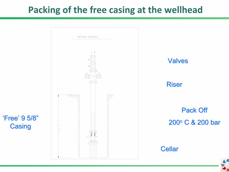
‘‘FreeFree’’ 9 5/89 5/8””CasingCasing
CellarCellar
Pack Off Pack Off
200200oo C & 200 barC & 200 bar
RiserRiser
ValvesValves
Packing of the free casing at the wellhead

1 2 3 4a 4b90.000 Events recorded
M 2.9
Hydraulic Stimulation GPK3

0
0.1
0.2
0.3
0.4
0.5
0.6
0.7
0.8
0.9
1
Inje
ctiv
ity/P
rodu
ctiv
ity in
dex
[l/(s
*bar
)]
Natural Injectivity / ProductivityHydraulic StimulationHClRMANTAOCA
GPK2 GPK3 GPK44%
76%
20%
GPK2
53%32%
8%8%
GPK3
2%
50%
8%13%
27%
GPK4
Status of wells prior to power production
17
Dimensioning of the power plant:
- production from GPK2 with a production pump - expected production is about35 l/s at 175 °C- Net power of 1.5 MWel
Nami et al., 2008
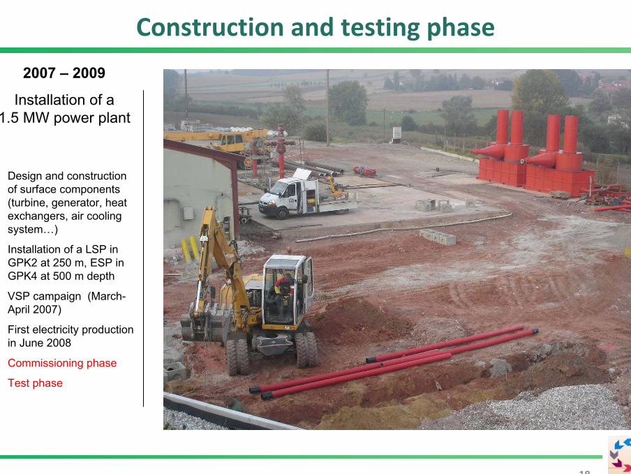
Construction and testing phase
1818
2007 – 2009
Installation of a 1.5 MW power plant
• Design and construction of surface components (turbine, generator, heat exchangers, air cooling system…)
• Installation of a LSP in GPK2 at 250 m, ESP in GPK4 at 500 m depth
• VSP campaign (March-April 2007)
• First electricity production in June 2008
• Commissioning phase
• Test phase

Design of power plant
19
Condenser
Evaporator
Preheater
G
Turbine
Generator
Pump
Regenerator
Gearbox
GPK3GPK2 GPK4
Line shaft punp at 350 m
ORC installation working with Isobutane
Thermal loop
GPK2/GPK3
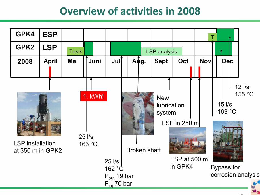
Overview of activities in 2008
20
GPK4 ESPGPK2 LSP
2008 April Mai Juni Juli Aug. Sept Oct Nov DecTests
LSP installation at 350 m in GPK2
1. kWh!
25 l/s163 °C
25 l/s162 °CPout 19 barPinj 70 bar
Broken shaft
LSP in 250 m
New lubricationsystem
15 l/s163 °C
T
12 l/s155 °C
ESP at 500 min GPK4 Bypass for
corrosion analysis
LSP analysis

Materials research
21
-> shaft failure due to friction and subsequentoverheating
-> erosion atimpellers
-> in-situ corrosion testing, test of inhibitors, online measurement of pH, T, redox potential, electricalconductivity

22
Corrosion analysis
P110 and N80 (Casings)
P265GH (surface lines)
Nominal composition of investigated steel samples:
(Baticci, 2009)

Line shaft pump in GPK2
23
• Installation depth: 350 m• max. power ~ 300 kW

Electric submersible pump in GPK4
24
Installation depth 500 m
Max. power ~ 300 kW
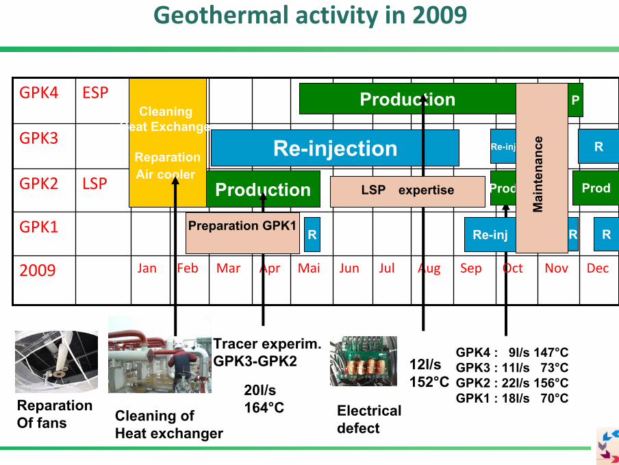
Geothermal activity in 2009
20l/s164°C
OctSep2009
GPK1
GPK2
GPK3
GPK4
DecNovAugJulJunMaiAprMarFebJan
LSP
ESP
Re-inj
Prod
Production
Re-inj
CleaningHeat Exchanger
ReparationAir cooler
Re-injection
R
Production
12l/s152°C
Cleaning ofHeat exchanger
Electricaldefect
ReparationOf fans
Tracer experim. GPK3-GPK2
LSP expertise
Preparation GPK1
GPK4 : 9l/s 147°CGPK3 : 11l/s 73°CGPK2 : 22l/s 156°CGPK1 : 18l/s 70°C
R
Prod
Mai
nten
ance
R
R
P

Acitivities in the next ‚Phase III‘
Starting Phase III: a 3 year program for a scientific and technical monitoring of the power plant with French and German funding
Reservoir: microseismicity, thermal monitoring, hydro‐chemical behaviour, tracer studies
Environmental monitoring: radioprotection, vibration study, noise,
Technological studies: Production pumps, Corrosion and Scaling
Summary and outlook
27
Actual status:
-> Circulation of the reservoir with production pumps has beensuccesfully demonstrated several times-> Components have been extensively tested-> A circulation with tracer investigation was performed and isunder evaluation-> The pilot plant is ready for the resumption of test operationsand acceptance-> reinjection into GPK1 tested
Start of Phase III with power production!

Feed‐in tarif
28
Feed-in tarif in France:
At the moment,l 12 ct/kWh are paid on the net power.
Increase to > 20 ct/kWh on net power is agreed fromall partners and contracts will be signed in the firstquarter of 2010..
Thank you for your attention!
And thanks to all scientific and technical partners in the Soultz projectand to the funding institutions BMU, ADEME und EU
as well as to the EEIG ‘Heat mining’.
29
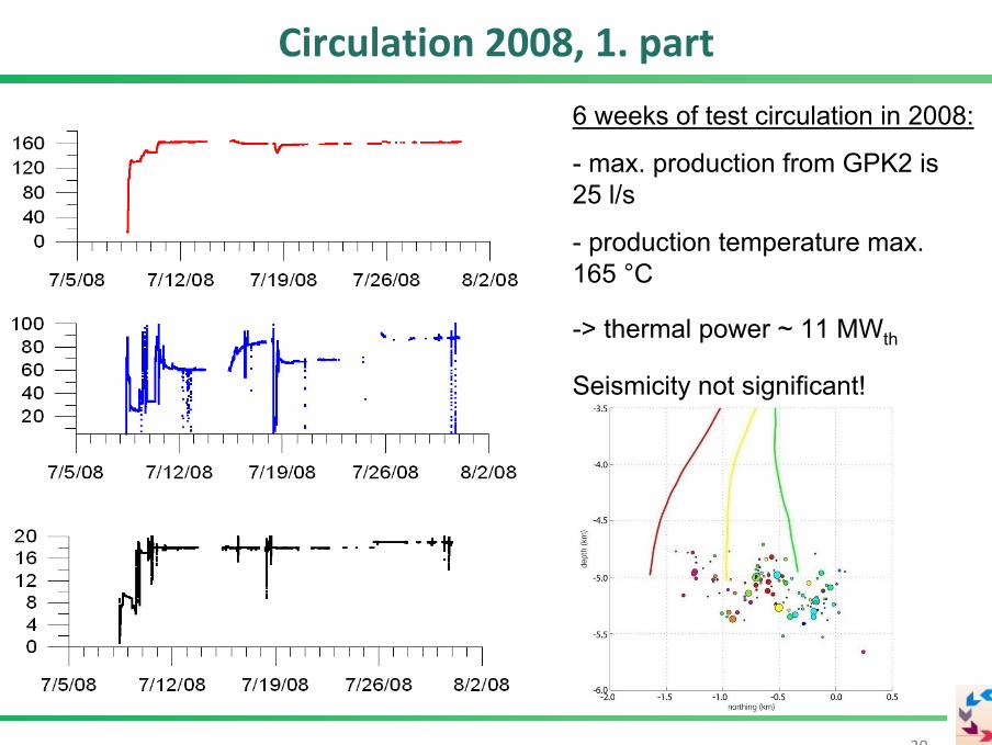
Circulation 2008, 1. part
30
6 weeks of test circulation in 2008:
- max. production from GPK2 is25 l/s
- production temperature max. 165 °C
-> thermal power ~ 11 MWth
Seismicity not significant!

31
Circulation 2008, 2. part
3 weeks of test circulation in 2008:
- GPK2 16 l/s, 163 °C
- GPK4 12 l/s, 155 °C
-> thermal power ~ 12 MWth
Seismicity not significant!
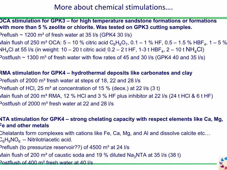
OCA stimulation for GPK3 – for high temperature sandstone formations or formationswith more than 5 % zeolite or chlorite. Was tested on GPK3 cutting samples.Preflush ~ 1200 m³ of fresh water at 35 l/s (GPK4 30 l/s)Main flush of 250 m³ OCA: 5 – 10 % citric acid C6H8O7, 0.1 – 1 % HF, 0.5 – 1.5 % HBF4, 1 – 5 % NH4Cl at 55 l/s (in weight: 10 – 20 t citric acid, 0.2 – 2 t HF, 1-3 t HBF4, 2 – 10 t NH4Cl)Postflush ~ 1300 m³ of fresh water with flow rates of 45 and 30 l/s (GPK4 40 and 35 l/s)
RMA stimulation for GPK4 – hydrothermal deposits like carbonates and clayPreflush of 2000 m³ fresh water at steps of 18, 22 and 28 l/sPreflush of HCl, 25 m³ at concentration of 15 % (deox.) at 22 l/s (3 t)Main flush of 200 m³ RMA, 12 % HCl and 3 % HF plus inhibitor at 22 l/s (24 t HCl & 6 t HF)Postflush of 2000 m³ fresh water at 22 and 28 l/s
NTA stimulation for GPK4 – strong chelating capacity with respect elements like Ca, Mg, Fe and other metalsChelatants form complexes with cations like Fe, Ca, Mg, and Al and dissolve calcite etc…C6H9NO6 -- Nitrilotriacetic acid.Preflush (to pressurize reservoir??) of 4500 m³ at 24 l/sMain flush of 200 m³ of caustic soda and 19 % diluted Na3NTA at 35 l/s (38 t)Postflush of 400 m³ fresh water at 40 l/s
More about chemical stimulations….


