THE ELECTRICAL AMPLIFYING STETHOSCOPE AND PHONO- ELECTROCARDIOSCOPE* By G. E. DONOVAN, M.Sc., M.B., D.P.H.f {The paper wasfirstreceived 3\st July, and in revised form 31s/ October, 1942. It was read before the WIRELESS SECTION 2nd December, 1942, and before the IRISH CENTRE 18//J March, 1943.) "I often say that when you can measure what you are speaking about, and express it in numbers, you know something about it; but when you cannot express it in numbers, your knowledge is of a meagre and unsatisfactory kind; it may be the beginning of knowledge, but you have scarcely in your thoughts, advanced to the stage of science, whatever the matter may be."'—Lord Kelvin, 1883. SUMMARY The important factors are discussed. A new method is described for the direct visual observation of the phonocardio- gram accompanied by a simultaneous electrocardiogram, or phonocardiogram plus sphygmogram, etc., at the patient's bedside. The heart sounds can be heard at the same time through a special electrical stethoscope which is incorporated in the apparatus. GLOSSARY OF MEDICAL TERMS Auscultation. Listening to sounds of the body for the purpose of diagnosis. For immediate auscultation the ear is placed directly against the body; for mediate auscultation a stetho- scope is used. Bruit. The French for "sound":—bruit de soufflet, bellows sound. Diastole. The dilatation of the heart; it is the period of relaxation or rest. Electrocardiogram. The graphic registration of the electrical variations of the heart. Phonocardiogram. The graphic registration of the heart sounds. Praecordium. The chest wall in front of the heart. Pre-systole. The period before the contraction of the heart. Sphygmogram. The graphic registration of the pulse waves. Systole. The period of the contraction of the heart. Thorax. The chest. (1) INTRODUCTION Many clinical methods are subjective and therefore lack accuracy. This is especially true of auscultation. It is not surprising that the recording of normal and abnormal heart sounds for the purpose of reference and study has for many years occupied the attention of physiologists and clinicians. The first attempts were made, according to Hirschfelder, 1 by Donders as long ago as 1856. Fredericq 2 carried out investigations in phonocardiography in 1892. The first graphic records were made by Einthoven and Geluk 3 with an electrical technique in 1894, but satis- factory phono-grams were not obtained until Einthoven 4 adapted his string galvanometer to the registration of heart sounds. O. Frank 5 had devised a direct method of graphically recording heart sounds with a stethoscopic attachment, a delicate resonating membrane and an optical recording device. Wiggers and Dean 6 further developed the direct method. Frederick and Dodge 7 intro- * Wireless Section paper. t Medical Officer of Health for the Llwchwr Urban and Gower Rural Districts. duced the thermionic vacuum-tube amplification system into this branch of medicine. With the perfection of crystal microphones and the development of vacuum-tube amplification a number of devices were introduced for converting the heart sounds into electrical variations, which when amplified are recorded by oscillographs having less sensitivity but greater frequency range. Workers such as Bierring, Bone and Lockhart, 8 and Schwarzschild and Feltenstein 9 used this method. A. Weber 10 and others have made intensive studies of the graphic recording and reproduction of heart sounds, in the laboratories of the Medical Institute in Bad Nauheim. Wolferth and Margolies 11 have been conducting interesting researches into phonocardiography for several years. The practical value of modern methods is shown by two recent mono- graphs, one by Orias and Braun-Menendez 12 who use a modification of the direct method of Frank; and the other by Calo 13 who uses the valve amplification system. A phonocardiogram is commonly accompanied by a simultaneous electrocardiogram. Kolliker and Muller 14 in 1855 had demonstrated by physiological experiments that the beat of the isolated frog's heart is accompanied by an electrical change. Waller 15 in 1887 showed that it is possible to demonstrate similar changes occurring in the human heart when electrodes are applied to the limbs. As his recording instrument was Lippman's capillary electro- meter, his experiments remained of academic interest only. It was not until Einthoven 16 in 1903 invented the string galvanometer that electrocardiography in its modern form became a clinical science. Many other types of electro- cardiograph have been made since the introduction of the original string galvanometer. Nearly all these instruments use some form of mirror galvanometer of comparatively low sensitivity in conjunction with an amplifier embodying thermionic vacuum tubes. Many workers, realizing the unique properties of the cathode-ray tube, adapted it to electrocardiographic work; among the first were Rijlant of Brussels, 17 Schmitz 18 and Matthews. 19 They used a cathode-ray tube merely as a recording device and not as an oscilloscope. Robertson and Bedford 20 devised a new electrocardiograph employing the cathode-ray tube as an oscilloscope. Triis instrument incorporated a screen having a long afterglow which permitted direct visual observation of the electrocardiogram. Brookes-Smith 21 devised a similar apparatus but without any device to obviate origin distortion. Recently, Brookes-Smith and Robertson have collaborated to produce a new electro- cardiograph. As far as the author is aware, details of this instrument have not yet been published in the technical journals. The Americans have adapted the cathode-ray afterglow screen to electrocardiography, and Asher and Hoecker 22 mention in their paper that Wilson of the [38]
Transcript
THE ELECTRICAL AMPLIFYING STETHOSCOPE AND PHONO-ELECTROCARDIOSCOPE*
By G. E. DONOVAN, M.Sc., M.B., D.P.H.f{The paper was first received 3\st July, and in revised form 31s/ October, 1942. It was read before the WIRELESS SECTION
2nd December, 1942, and before the IRISH CENTRE 18//J March, 1943.)
"I often say that when you can measure what you are speakingabout, and express it in numbers, you know something aboutit; but when you cannot express it in numbers, your knowledgeis of a meagre and unsatisfactory kind; it may be the beginningof knowledge, but you have scarcely in your thoughts,advanced to the stage of science, whatever the matter maybe."'—Lord Kelvin, 1883.
SUMMARYThe important factors are discussed. A new method is
described for the direct visual observation of the phonocardio-gram accompanied by a simultaneous electrocardiogram, orphonocardiogram plus sphygmogram, etc., at the patient'sbedside. The heart sounds can be heard at the same timethrough a special electrical stethoscope which is incorporated inthe apparatus.
GLOSSARY OF MEDICAL TERMSAuscultation. Listening to sounds of the body for the purpose
of diagnosis. For immediate auscultation the ear is placeddirectly against the body; for mediate auscultation a stetho-scope is used.
Bruit. The French for "sound":—bruit de soufflet, bellows sound.Diastole. The dilatation of the heart; it is the period of
relaxation or rest.Electrocardiogram. The graphic registration of the electrical
variations of the heart.Phonocardiogram. The graphic registration of the heart sounds.Praecordium. The chest wall in front of the heart.Pre-systole. The period before the contraction of the heart.Sphygmogram. The graphic registration of the pulse waves.Systole. The period of the contraction of the heart.Thorax. The chest.
(1) INTRODUCTIONMany clinical methods are subjective and therefore lack
accuracy. This is especially true of auscultation. It isnot surprising that the recording of normal and abnormalheart sounds for the purpose of reference and study hasfor many years occupied the attention of physiologists andclinicians. The first attempts were made, according toHirschfelder,1 by Donders as long ago as 1856. Fredericq2
carried out investigations in phonocardiography in 1892.The first graphic records were made by Einthoven andGeluk3 with an electrical technique in 1894, but satis-factory phono-grams were not obtained until Einthoven4
adapted his string galvanometer to the registration of heartsounds. O. Frank5 had devised a direct method ofgraphically recording heart sounds with a stethoscopicattachment, a delicate resonating membrane and anoptical recording device. Wiggers and Dean6 furtherdeveloped the direct method. Frederick and Dodge7 intro-
* Wireless Section paper.t Medical Officer of Health for the Llwchwr Urban and Gower Rural
Districts.
duced the thermionic vacuum-tube amplification systeminto this branch of medicine. With the perfection ofcrystal microphones and the development of vacuum-tubeamplification a number of devices were introduced forconverting the heart sounds into electrical variations,which when amplified are recorded by oscillographs havingless sensitivity but greater frequency range. Workers suchas Bierring, Bone and Lockhart,8 and Schwarzschild andFeltenstein9 used this method. A. Weber10 and othershave made intensive studies of the graphic recording andreproduction of heart sounds, in the laboratories of theMedical Institute in Bad Nauheim. Wolferth andMargolies11 have been conducting interesting researchesinto phonocardiography for several years. The practicalvalue of modern methods is shown by two recent mono-graphs, one by Orias and Braun-Menendez12 who use amodification of the direct method of Frank; and the otherby Calo13 who uses the valve amplification system.
A phonocardiogram is commonly accompanied by asimultaneous electrocardiogram. Kolliker and Muller14
in 1855 had demonstrated by physiological experimentsthat the beat of the isolated frog's heart is accompanied byan electrical change. Waller15 in 1887 showed that it ispossible to demonstrate similar changes occurring in thehuman heart when electrodes are applied to the limbs. Ashis recording instrument was Lippman's capillary electro-meter, his experiments remained of academic interest only.It was not until Einthoven16 in 1903 invented the stringgalvanometer that electrocardiography in its modern formbecame a clinical science. Many other types of electro-cardiograph have been made since the introduction of theoriginal string galvanometer. Nearly all these instrumentsuse some form of mirror galvanometer of comparativelylow sensitivity in conjunction with an amplifier embodyingthermionic vacuum tubes. Many workers, realizing theunique properties of the cathode-ray tube, adapted it toelectrocardiographic work; among the first were Rijlantof Brussels,17 Schmitz18 and Matthews.19 They used acathode-ray tube merely as a recording device and not asan oscilloscope. Robertson and Bedford20 devised a newelectrocardiograph employing the cathode-ray tube as anoscilloscope. Triis instrument incorporated a screenhaving a long afterglow which permitted direct visualobservation of the electrocardiogram. Brookes-Smith21
devised a similar apparatus but without any device toobviate origin distortion. Recently, Brookes-Smith andRobertson have collaborated to produce a new electro-cardiograph. As far as the author is aware, details ofthis instrument have not yet been published in the technicaljournals. The Americans have adapted the cathode-rayafterglow screen to electrocardiography, and Asher andHoecker22 mention in their paper that Wilson of the
[ 3 8 ]
DONOVAN: THE ELECTRICAL AMPLIFYING STETHOSCOPE AND PHONO-ELECTROCARDIOSCOPE 39
University of Michigan uses this principle, and the latercommercial Dumont and Hindle instruments incorporateit. The foregoing instruments use the conventional single-beam cathode-ray tube.
The present apparatus incorporates a double-beamcathode-ray oscilloscope with a fluorescent screen of longafterglow. This permits the simultaneous direct visualobservation of two phenomena such as the phonocardio-gram and electrocardiogram, or sphygmogram and phono-cardiogram, etc., at the patient's bedside. The amplifiedheart sounds can be heard at the same time. The instru-ment is called a phono-electrocardioscope.
(2) LAWS GOVERNING AUSCULTATIONAn instrument for cardiac auscultation, whether it be
the simple stethoscope or the more complicated thermionicvacuum-tube amplifier type, is nothing more than a hearing-aid. A knowledge of acoustics is desirable for a physicianto get maximum benefit from the use of such an aid.
Rappaport and Sprague23 stress the following:—(a) Tones of different periods of oscillation or frequency,
but of similar intensity, affect the human ear to differentdegrees.
(b) The minimum change in intensity of a sound stimulusto which the human ear is capable of responding varieswith the general level of the sound, as well as with its fre-quency. In the auscultatory frequency band, as the fre-quency of the stimulus is lowered, a decidedly greater per-centage variation in intensity is therefore required toproduce the minimum perceptible change.
(c) The human ear is a better detector of changes infrequency than of change in intensity. A sound stimuluswith a high sensation level requires less of a frequencyvariation to produce minimum susceptibility than does asound stimulus of a lower sensation level. Also, the earis somewhat less sensitive to frequency variations at thelower end of the auscultatory frequency band than it is tovariations in the upper region.
(d) In the auscultatory frequency band, the frequency ofa stimulus may be varied rapidly over a considerableportion of an octave without detection by the ear.
(e) The auditory sensation produced by a complex soundmay be decidedly different in character, as well as in theintensity, when the stimulating level is decreased or in-creased, even though no distortion is introduced. As acomplex sound, such as a heart murmur, becomes moreintense, the low-pitched components appear more pro-minent to the observer.
(/) When a sound of comparatively high intensity im-mediately precedes a sound of considerably lower intensity,masking of the sound of lower intensity may result.
(g) The larger the diameter of the open stethoscopicchest-piece, the better its response to low-pitched sounds.This is accomplished at the expense of the higher-frequency components.
(//) The greater the pressure with which the open stetho-scopic chest-piece is applied to the patient's chest, thebetter is the response of the stethoscope to higher-frequencycomponents. Thus, by varying the application pressure,the physician exerts a variable filtering action upon thesounds because the natural period of the skin diaphragmbounded by the chest-piece depends on the applicationpressure.
The author would add to the foregoing:(;) The trained ear of a physician is capable of con-
centrating on, and picking out, those sounds which hebelieves are desirable for his diagnosis. The mind exertsa selective discrimination.
(k) If an auscultator expects to find a certain conditionpresent, when auscultating, it tends to induce in him amental state which provides a bias towards hearing whathe expects to hear. This has potential dangers.
(/) It is commonly held that some persons have afaculty described as "absolute pitch." The averagephysician believes in a similar faculty which can bedescribed as "absolute loudness." This, in the opinion ofthe author, is incorrect.
(3) HEART SOUNDS, BRUITS AND NON-CARDIACTHORACIC SOUNDS FROM A PHYSICAL POINTOF VIEW
The wave-form of vibrations of the skin of the chestwall, due to the underlying cardiac action, is of a compositenature. There are relatively gross movements and a seriesof finer vibrations. The vibrations depend upon the heart,the paths along which these vibrations have to travel toreach the surface, and other factors which will be discussedlater. The gross mechanical movement due to the apexbeat of the heart appears to have no clinical importancefrom the auscultatory point of view. Some of the finervibrations reach a sufficiently high frequency which allowsthe ear to interpret them as sound.
The auscultatory sounds of interest in auscultation aremade up of frequencies below 1 000 c./s. It is estimatedthat the lower frequency limit of heart sounds and murmurcomponents is in the vicinity of 5-10 c./s., although30-40 c./s. is the lower limit of audibility. Low-pitchedcardiac murmurs are composed of frequency componentsbelow 400 c./s., and high-pitched murmurs range from120 to 660 c./s. Systolic and diastolic murmurs are com-posed chiefly of energy components between 120 and660 c./s., but occasionally ascend to 1 000 c./s. The fre-quency of pre-systolic murmurs lies mainly below 140 c./s.but may have components up to 400 c./s.
When the bell of a stethoscope or the chest-piece of amicrophone is applied to the praecordium, an instantchange takes place in the wave-form of vibrations occurringthere. The pressure and type of bell, as pointed out byRappaport and Sprague,23 affect the frequency response.The skin enclosed by the bell piece of a stethoscope maybe likened to the diaphragm of a headphone. The move-ment of the skin, like the diaphragm, has to create apressure variation in a confined volume of air, viz. in thespace enclosed between the ears and the skin. Anyleakage in this volume must affect the frequency response.This may occur at the contact between the skin and thebell-piece, and between the earpieces and the ears.
Heart sounds when detected with the stethoscope are asensation. As pointed out elsewhere, the relationshipbetween the stimulus and the sensation is a very complexone. The sensation, being subjective, cannot be directlymeasured. Heart sounds when registered in oscillographicform can be directly measured.
Since the heart sounds vary so much with the methodused to detect them, it is desirable from a strictly scientificpoint of view that apparatus and the conditions under
40 DONOVAN: THE ELECTRICAL AMPLIFYING STETHOSCOPE
which such apparatus is used should be standardized.This will be discussed later. An ophthalmologist has hisown refraction corrected, or he allows for the error in hisown refraction when refracting his patient's eyes. It wouldbe an advantage for the auscultator to have his hearingsimilarly tested so that he can allow for errors in hishearing.
(4) GENERAL CONSIDERATIONSFrom the material presented so far, we may conclude
that the human ear in auscultation has many faults. Theacoustic stethoscope does not correct for the characteristicsof the ear, and does not lend itself to any great radicalimprovement in design. We must look to electricalamplifying devices for such improvements. There is atemptation for a worker in this field to rely on objectivemethods which can be directly measured, and to ignoreauscultation, which is a subjective method. This shouldbe resisted as a physician has spent many years in acquiringhis auscultatory technique, and he cannot afford lightly todiscard it and learn all over again a new method whichcan only with great difficulty be correlated to his previousexperience. The solution is that the sensation of hearingshould be correlated with an objective reality, viz. a phono-cardiogram. In order to time accurately the events of thecardiac cycle, an electrocardiogram or sphygmogramoccurring simultaneously should accompany a phono-cardiogram. The phono-electrocardioscope is designedon the above principles.
The following are some of the more important factorsthat must be taken into consideration in designing anamplifying stethoscope.
(a) The apparatus must be capable of faithfully repro-ducing sounds.
Channel I
(b) It must be free from pick-up due to external electricalwiring, X-ray apparatus, etc.
(c) It must be free of any inherent noise.(d) The apparatus should not be affected by normal room
noises or vibrations.(e) The sound volume should be controllable.(/) Acoustic feed-back should be eliminated.(g) The apparatus must be at least as sturdy as a radio
set.(h) It must incorporate devices which can overcome,
whenever possible, the natural human ear defects whichinterfere with auscultation.
The phonocardioscopic part must have the followingfunctions:—
(a) It must show, in oscillographic form, all the heartsounds that are audible with the stethoscope.
(b) It must be able to show sounds which are easilymissed as a result of masking, etc.
(c) It must be immune to all types of external electricalinterference.
The electrocardioscopic part must be capable of fittingin with all the normally accepted standards and require-ments. In addition it would be an advantage if this partcould be used for the registration of the sphygmogram, assometimes an electrocardiogram is not sufficient for theinterpretation of the events occurring in the cardiac cycle.
(5) GENERAL COMPONENT RELATIONSHIPSFig. 1 is a schematic diagram of the connections and
plan of the phono-electrocardioscope, and Fig. 2 shows aview of the apparatus in use. The apparatus consists offour portable mechanically robust units, viz. the amplifierunit, the oscilloscope unit, the high-tension unit and thecamera unit.
AMPLIFYING UNIT
Calibrating Devict forthe Heart, Sound Amplifiers
-Gain Control farY2 Deflector Plate
DOUBLE BEAM CATHODE RAY OSCILLOSCOPE
Ts Electricity Mains.
A * Amplifier for Channel 2B > do. do. IC • da do 3
Fig. 1.—Schematic diagram of the phono-electrocardioscope.
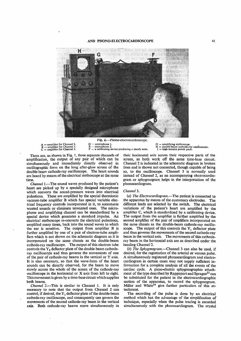
AND PHONO-ELECTROCARDIOSCOPE 41
A •=> amplifier for Channel 2.B <=> amplifier for Channel 1.C •= amplifier for Channel 3.
Fig. 2.—Phono-electrocardioscope.D <= microphone 1. GE « microphone 2. H •F = a calibrating device producing a steady note. I
• amplifying stethoscope.• double-beam cathode-ray oscilloscope.> high-tension power pack.
There are, as shown in Fig. 1, three separate channels ofamplification, the output of any pair of which can besimultaneously and immediately directly observed inoscillographic form on the long after-glow screen of thedouble-beam cathode-ray oscilloscope. The heart soundsare heard by means of the electrical stethoscope at the sametime.
Channel 1.—The sound waves produced by the patient'sheart are picked up by a specially designed microphonewhich converts the sound-pressure waves into electricalpulsations. These are amplified by the special thermionicvacuum-tube amplifier B which has special variable elec-trical frequency controls incorporated in it, to accentuatewanted sounds or eliminate unwanted ones. The micro-phone and amplifying channel can be standardized by aspecial device which generates a standard impulse. Anelectrical stethoscope re-converts the electrical pulsations,amplified many times, back into the sound waves to whichthe ear is sensitive. The output from amplifier B isfurther amplified by one of a pair of electron-tube ampli-fiers which is not shown on the schematic diagram as it isincorporated on the same chassis as the double-beamcathode-ray oscilloscope. The output of this electron tubecontrols the Y2 deflector plate of the double-beam cathode-ray oscilloscope and thus governs the movements of oneof the pair of cathode-ray beams in the vertical or Y axis.It is also necessary, so that the wave-form of the heartsounds can be directly observed, for the beam to moveslowly across the whole of the screen of the cathode-rayoscilloscope in the horizontal or X axis from left to right.This movement is given by a time-base circuit which suppliesboth beams.
Channel 2.—This is similar to Channel 1. It is onlynecessary to note that the output from Channel 2 cancontrol, if desired, the Yj deflector plate of the double-beamcathode-ray oscilloscope, and consequently can govern themovements of the second cathode-ray beam in the verticalaxis. Both cathode-ray beams move simultaneously in
their horizontal axis across their respective parts of thescreen, as both work off the same time-base circuit.Channel 2 is indicated in the schematic diagram in brokenlines and is shown not connected, though capable of beingso, to the oscilloscope. Channel 3 is normally usedinstead of Channel 2, as an accompanying electrocardio-gram or sphygmogram helps in the interpretation of thephonocardiogram.
Channel 3.(a) The Electrocardiogram.—The patient is connected to
the apparatus by means of the customary electrodes. Thedifferent leads are selected by the switch. The electricalvariations of the patient's heart are amplified by theamplifier C, which is standardized by a calibrating device.The output from the amplifier is further amplified by thesecond amplifier of the pair of amplifiers incorporated onthe same chassis as the double-beam cathode-ray oscillo-scope. The output of this controls the Y! deflector plateand thus governs the movements of the second cathode-raybeam in the vertical axis. The movements of this cathode-ray beam in the horizontal axis are as described under theheading Channel 2.
(b) The Sphygmogram.—Channel 3 can also be used, ifdesired, for the registration of the arterial or venous pulse.A simultaneously registered phonocardiogram and electro-cardiogram in certain cases may not supply sufficient in-formation for a complete analysis of all the events of thecardiac cycle. A piezo-electric sphygmographic attach-ment of the type described by Rappaport and Sprague23 canbe substituted for the patient in the electrocardiographicsection of the apparatus, to record the sphygmogram.Miller and White24 give further particulars of this at-tachment.
The recording of the pulse is done by an electricalmethod which has the advantage of the simplification oftechnique, especially when the pulse tracing is recordedsimultaneously with the phonocardiogram. The crystal
42 DONOVAN: THE ELECTRICAL AMPLIFYING STETHOSCOPE
microphone which normally can be used for the heartsounds is mounted in an air-tight housing, so that the aircolumn of the pick-up device (funnel or pelotte) and therubber tubing which connects the pick-up device to themicrophone diaphragm form a completely sealed space.The capacitance of the crystal microphone is artificially in-creased by the expedient of shunting an external fixed con-denser across it. The effect of this is that the time-constantof the input circuit is sufficiently high to record such lowfrequencies as the pulse waves. The value of the shuntcapacitance is a compromise between large capacitance,more accurate recording and lower output on the one hand,and small capacitance, less accurate recording and a higheroutput on the other hand.
(6) THE MICROPHONEBoth Channels 1 and 2 (see Fig. 1) require a microphone
to pick up the heart sounds. Many forms of microphonewere experimented with before the present one was de-cided upon. This microphone, which is shown as a cross-section sketch in Fig. 3, was found to be the most satis-
~Mttol ContainerRikbir Saldtrtd iron ring Bimorph Pieu-llectn'c Crystal
(ftotKt 118/Salt)
Fig. 3.—Section through special microphone. The valve is toprevent the microphone from being damaged when it isapplied to the chest, and is closed while the heart soundsare being registered.
factory. The fundamental frequency of the bimorphcrystal incorporated in the microphone is approximatelylOOOOc./s. The fundamental frequency is lowered to afew thousand cycles per second when a diaphragm iscoupled to the crystal. This is very much higher than theupper frequency limits encountered in auscultatory work.The piezo-electric crystal element used in this microphonepossesses many characteristics which make it suitable forphonocardiography; the following are some of the mostimportant:—
(a) Freedom from parasitic noises.(6) Lightness.(c) Sensitivity.(d) Requires only electrostatic shielding.(e) No necessity for a coupling transformer.(/) Does not require polarizing potentials,(g) Is comparatively robust.
The diameter of that part of the microphone which isapplied to the patient's chest is 5 cm. This is rather largerthan usually employed, but is deliberately made so as thefrequency response of the microphone is not so modifiedby the pressure by which the microphone is applied to thechest wall. The air chamber in front of the piezo-electricelement is shallow in depth, but not so shallow as to per-mit the skin of an obese patient to come in contact with the
diaphragm of the crystal unit. A funnel type of arrange-ment can be fitted to the front of the microphone if desired.
The air-pressure equalizing valve (see Fig. 3) serves theessential purpose of protecting the crystal from injurywhile the microphone is being applied to the chest wall.The sudden high pressure of extremely low frequency whichoccurs at this instant is allowed to escape through the openvalve. This valve ensures that the air imprisoned betweenthe diaphragm of the microphone and the skin of thepatient is at atmospheric pressure. The valve is closedwhilst the heart sounds are being registered.
The crystal microphone cartridge is mounted betweenrubber rings and the case of the microphone has an outercovering of rubber. This has the effect of immunizing themicrophone to extraneous mechanical shocks and noises.It can, if desired, be held manually in position on thepatient's praecordium, but it is of course better to keepthe microphone in position by means of a rubber band.
Some workers in phonocardiography use a microphoneso constructed that its case has incorporated in it a devicewhich acts as an acoustic high-pass filter. Four bells orchest-pieces are used in conjunction with such a micro-phone, each producing a different degree of filtering action.The desired bell is usually screwed into the microphonecase. No attempt is made in the microphone of Fig. 3to vary its frequency response by means of different bells.The chest-piece is constant always. The microphonerelying on different bell-pieces to change its frequencycharacteristics has the following disadvantages:—
(a) The microphone has to be removed from the areawhich is being auscultated in order to fit the appropriatebell-piece in the microphone case to get the desired filteringaction.
(b) These bell-pieces will not be applied to exactly thesame area that was previously being auscultated, especiallyas the bell-pieces differ in size.
(c) It is only by chance that the chest-pieces of themicrophone will be applied to the praecordium withexactly the same pressure as the microphone was appliedbefore. This will upset the filtering action.
It is better that any filtering action be done through themedium of electric filter controls incorporated in thethermionic vacuum-tube amplifier.
(7) THE HEART-SOUND AMPLIFIERSEach of the special pair of amplifiers which are marked
A and B in Figs. 1 and 2, and of which a circuit diagramis shown in Fig. 4, are resistance-capacitance-coupled andfitted with frequency-discriminating circuits which enablethe investigator to accentuate, or attenuate at will, eitherhigh or low frequencies.
(7.1) Amplifier AThe thermionic vacuum tubes incorporated in this
amplifier are of the high-frequency pentode type and givegreat amplification. The gain and frequency range aremore than adequate for heart sound amplifications. Nomatter how weak a sound is it can be brought up tooptimum level. A gain control is incorporated betweenthe first and second thermionic vacuum tubes.(7.1.1) Frequency-Discriminating Circuits.
Two different types of frequency discriminating circuitscontrol the frequency response of the amplifier. They
AND PHONO-ELECTROCARDIOSCOPE 43
Hiqh Tinsien +
MicrophoneL-H.-IThe frttyiiney contrail are also shownAmplifier B is similar, but has onevtra Amplifying Staqt ta Supply theElectrical SteDioicope
Fig. 4.—Basic circuit of the heart-sound amplifier A.
H . T -
depend for their action on the fact that the frequencyresponse of the amplifier at the low-frequency end of theamplifying band is directly dependent upon the magnitudeof the coupling condensers in relationship to the rest ofthe circuit, and the response at the high-frequency end ofthe amplifying band is inversely dependent upon themagnitude of the shunt capacitance in relationship to thecircuit resistances.
A rotary type of switch is arranged to bring differentvalues of interstage condensers into action as it is rotated.The switch snaps from one position to the next so thatthere is no fear that the same filtering action cannot berepeated as often as required.
It is interesting to note that the most complete investiga-tions on filtering action have been carried out for electricaltypes. However, the analyses of the acoustic and mech-anical types of filters have been worked out and are similarto those of the electrical types. The phonocardiographemployed by Einthoven possessed a simple but crude sortof high-pass acoustic filter. Because his method allowedaccess between the external air and the air column whichwas under heart-sound excitation, extraneous noises wereliable to be introduced. This is also one of the disad-vantages of the Wiggers and Dean's method and its variousmodifications. The phono-electrocardioscope obviouslyhas not this inherent fault.
As can be seen from Fig. 4, a filter is incorporatedbetween the plate of the first thermionic tube and the low-tension negative, to filter out the high-frequency compo-nents, leaving the low-frequency ones.
These do not curtail suddenly the frequency band at aparticular point, but rather act like acoustic filters. Thisis an advantage as the heart sounds are not pure notes butmore in the nature of noises.
A point to be noted is that 25 different combinations canbe obtained simply by rotating two switches. This takesonly a few moments to perform, whereas it is difficult toaccomplish with acoustic or mechanical filters.
(7.2) Amplifier BThis is similar to amplifier A previously mentioned. It
permits the heart sounds of one area to be compared withthose of another, for instance the first sound at the apexto the second sound at the base of the heart. The ratiobetween these sounds varies in myocardial degeneration.The amplifying channels 1 and 2 (see Fig. 1) are used forthis purpose.
(7.2.1) Tone-Compensated Gain Control.The output of either amplifier A or B can be connected
directly across the input A terminals of Fig. 5 without
of
disturbing the operation of the" cathode-ray oscillograph, as a 1-MQ fixed resistoris retained in the upper end of the com-pensated potentiometer.
Rappaport and Sprague23 state "thatan amplifying stethoscope is not prim-arily an instrument to be used for makingsounds many times louder than they canbe heard with an acoustic stethoscope.The major advantage of the amplifyingstethoscope over the acoustic stetho-scope is that the intensity can be ad-justed as desired, and thus a number
modifying characteristics which cannot be over-come with the acoustic stethoscope are eliminated.Roughly, the heart-sound intensity in a normal youngperson, as perceived by auscultation with an acousticstethoscope, is approximately optimal from a standpointof masking, pitch, quality and accustomed usage of theolder acoustic stethoscope." The tone-compensated gaincontrol helps to correct for the deficiency in the human earpreviously mentioned in which the auditory sensation pro-duced by complex sounds may be decidedly different incharacter as well as intensity when the stimulating level isincreased or decreased. This device allows greater latitudein varying the intensity levels at which the heart sounds areheard.
Input A
ElectricalStlthttcipl
Fig. 5.—Tone-compensated gain control.
Fig. 5 is a circuit diagram of the tone-compensated gaincontrol. The response curves (see Fig. 6) shown, for
.10
• to
• 30
•At
S * I
•- — —
Setting
Fig. 6.—Response curves for various positions of the tone-compensated gain control.
various positions of the potentiometer, were obtained bydirect measurement on the circuit. They approximate tothe contours of equal subjective hearing on the Fletcherand Munson curves, and hence represent the necessaryfrequency compensation.
(8) THE AUDIOPHONEThe audiophone is the component of an amplifying
stethoscope which converts the amplified electrical pulsa-
44 DONOVAN: THE ELECTRICAL AMPLIFYING STETHOSCOPE
tions into equivalent sounds such as those which arenormally heard with the acoustic stethoscope. It consistsof an electro-acoustic transducer and binaural. Thetransducer is an earphone which was selected because of itssimple construction, rugged nature, ability to cover the re-quired frequency band, compactness and suitable impe-dance characteristics. A headphone could be applieddirectly to the ear without the intermediary of the binaural.The reason that the binaural is used is that the averageauscultator prefers to hear the cardiac sounds through thismedium.
(9) CALIBRATING DEVICE FOR THE HEART-SOUNDAMPLIFIERS
The amplifying channel can be standardized by injectinga small constant voltage into the input circuit. The con-trols are set in such a position and the frequency of thestandardizing impulse is such that the amplifier will notdistort.
If desired, a constant note of 50 c./s. can be developed.The sound can be picked up by placing a microphone incontact with it and adjusting the gain control of theamplifier so that the cathode-ray spot gives a standarddeflection. The author prefers to inject a small voltageinto the input circuit.
(10) THE ELECTROCARDIOGRAPHIC AMPLIFIERThe circuit diagram of this part of the apparatus is
shown in Fig. 7. It consists of a specially designed 3-stage
Fig. 7.—Basic circuit diagram of the electrocardiographic amplifier C.
resistance-capacitance coupled amplifier. The thermionic
stantaneously to the potential which is applied to its de-flector plates. It is not easily damaged by a high voltage.Due to its very high impedance it causes negligible dis-turbance to any circuit to which it is connected. Mostmeters are restricted to one dimension, but a cathode-rayoscillograph can respond to two or even three dimensionssimultaneously. When a linear time-base is applied to thehorizontal deflector plates, the variations of electricalpotentials from any source, for instance the electrocardio-gram, can be studied in relation to time. By the use of atube with a screen of long afterglow, very slow phenomenacan be observed as a trace lasting some seconds, and with-out the necessity of waiting for the development of photo-graphic material. The direct examination is the next bestthing to direct recording as by an ink-writing mechanism.In such an apparatus the inertia of the moving part andthe friction between the pen and the writing surface causedistortion of the curves, except for the slowest-moving,e.g. the Berger phenomena of the brain. The cathode-raytube is robust and more or less unaffected by mechanicalshocks.
(11.1) The Doable-Beam TubeAlthough the ordinary single-beam tube plus a little in-
genuity clarifies the majority of problems, a still wider fieldof usefulness is opened up if we have two beams to use inone tube, for this allows two independent phenomena tobe recorded without additional apparatus.
The single-beam cathode-ray tube has been used indifferent branches of medicine, but so far as theauthor is aware the double-beam cathode-rayoscilloscope fitted with a long afterglow screenhas never previously been used in phonocardio-graphy, electrocardiography and sphygmography.The fact that the double-beam cathode-ray tubehas two spots capable of independent deflectionin the Y-direction whilst being deflected simul-taneously in the X-direction by a common time-base, permits the direct visual simultaneous andcontinuous observation of two phenomena suchas a phonocardiogram and an electrocardiogram,or a phonocardiogram and a sphygmogram.
Hiqh Tension +
vacuum tubes used are triodes. The intercoupling time-constants are long, so that there is no distortion. Thehigh-frequency response of the amplifier is limited by filtercircuit arrangements so that the amplifier, though sensitive,is still very stable. The filter circuit time-constants are sochosen that there is no distortion of the higher-frequencycomponents of the electrocardiogram. It is also adequatefor the sphygmogram.
(10.1) Calibrating Device of the ElectrocardiographicAmplifier
A press-key calibrating device is arranged to apply 1 mVinput between the grid and the filament of the first valveof the amplifying channel, and the amplification is adjustedto give a standardized deflection on the screen of thecathode-ray tube.
(11) THE DOUBLE-BEAM CATHODE-RAYOSCILLOSCOPE
The cathode-ray tube is unique as an electrical recordinginstrument as it has no inherent inertia. It responds in-
(11.2) The Fluorescent Screen of the Double-BeamCathode-ray Oscilloscope
It is only by the use of a tube with a fluorescent screenof very long afterglow that direct visual observation of thephonocardiogram and electrocardiogram is possible.Without this afterglow or phosphorescence, the eye couldnot appreciate the wave form of the traces, even thoughcorrectly traced by the cathode-ray spots. The phos-phorescence is sufficiently persistent to leave several heartcycles simultaneously visible on the screen.
(11.3) The Time-baseThe time-base used has the circuit shown in Fig. 8, in
which the condenser charges through the pentode valveand is discharged by the gas-filled triode. The constant-current characteristic of the pentode ensures a linear timebase.
(11.4) Viewing-Hood and GraticuleIn order to prevent direct light falling on the screen of
the cathode-ray tube, a viewing hood which is a form ofdark tunnel is fitted into the surround around the front of
AND PHONO-ELECTROCARDIOSCOPE 45
FJ'R. 8.- Scanning circuit employing a pentode in place of thecharging resistance.
the tube. It also provides a base to which a camera canbe attached. A transparent 10-cm. graticule slides in frontof the screen of the tube to assist .in quantitative de-termination.
(12) POWER SUPPLYThe amplifiers A, B and C (see Fig. 1) are battery-
operated. They get their power from the high-tensionbatteries ordinarily used in wireless, and 2-volt accumu-lators. The cathode-ray oscilloscope is mains-operated.
(12.1) Hum NeutralizationThere is little danger of picking up electrical interference
from the mains wiring in the room where the apparatus isused, when the instrument is operating as a combinedphonocardiograph and sphygmograph. The author has
Fig. 9
never found difficulty from mains interference when theapparatus is working as an electrocardiograph. If suchan interference occurred, it could be cured by arranging acircuit which would oppose the interfering sine-wavevoltage by a sine wave of the same frequency equal inamplitude and opposite in phase. Since the hum is dueto interference picked up by the mains wiring, the hum-neutralizing voltage is obtained from the mains. Abalanced input amplifier is used by some workers for theelimination of this type of interference.
A mumetal shield is used with the cathode-ray tube as aprotection against magnetic fields. The author would havepreferred to use mumetal shields in other parts of theapparatus, such as the transformers, but owing to war con-ditions could not procure them. If they were incorporatedin the apparatus, the whole instrument could be madeabout one-third of its present size and still be free fromunwanted pick-up.
(12.2) Photographic Recording of the Cathode-rayImage
It is perfectly feasible to focus a camera on thefluorescent screen of the double-beam cathode-ray oscillo-
scope and to take one traverse of the pair of spots as theyappear for visual observation—opening the shutter at thebeginning and closing it at the end of the traverse of thespots. As a matter of fact, the records illustrating thispaper (Figs. 10-15) were taken by such a method, as it wasthought advisable to give the reader an idea of what theseimages looked like. The linear movements of the pair ofspots across the screen permit this. Generally it is diffi-cult, owing to the curvature of the end of the oscillographictube, to get an accurately focused image of the spots overthe whole length of their traverse. This is overcome byusing a reflex camera employing a 35-mm. film. It wasrealized that the resulting photographs would not showsuch fine traces as if they were taken by a recording cameraworking with moving film, and would be technically in-ferior. The actual images on the screen must be seen tobe properly appreciated.
The records were obtained by focusing the camera onthe fluorescent screen of the double-beam cathode-rayoscilloscope, and photographing the traverse of the pairof spots as they appear for visual observation, openingthe shutter at the beginning and closing it at the end ofthe traverse of the spots. This method was adoptedrather than taking the records by means of a rotating-drum camera, as it was thought that it would give thereader a better idea of what is the main advantage of the
apparatus, viz. the appearance of the doubleoscillogram on the fluorescent screen.
Where permanent records are desirable,it is better to use a camera working withmoving film and with the spots stationary inthe horizontal or X direction, so that themovements of the spots become strictly com-parable with the movements of the string ofthe string galvanometer. The afterglow ofthe spots compared with the direct responseis not sufficiently actinic to affect the photo-graphic film. The great advantage of thismethod from the point of view of records forpublication is that the traces on the film are
very fine. This is due to the fact that the camera canbe so arranged that the images on the film will be on amuch reduced scale compared with those on the fluorescentscreen. The apparent reduction in movements of thespots can be compensated by adjusting the gain control ofthe electrocardiographic amplifier.
The moving-film method of recording does not preventthe simultaneous observation of the phonocardiogram andelectrocardiogram, or phonocardiogram and sphygmo-gram, since the "time base" on one double-beam oscillo-graph can be easily stopped by short-circuiting its X platesto the gun, while allowing it to function on another double-beam cathode-ray tube running parallel from the sameamplifier unit. A few simple precautions can be adoptedto make this arrangement work satisfactorily.
(13) TECHNIQUEThe power supply to the different parts of the apparatus
is switched on, the velocity control of the double-beamcathode-ray oscilloscope is adjusted to give the desired rate(a traverse time of 2} sec. for normal work is satisfactory),and the brilliancy control to give the necessary intensity.The time-base amplitude control is so adjusted as to allow
46 DONOVAN: THE ELECTRICAL AMPLIFYING STETHOSCOPE
Fig. 10.—Illustrative record 1. Healthy child—normal.Electrocardiogram lead II.Phonocardiogram, mitral area.
Slight sinus arrhythmia which is normal. The slight roughness of thebase line is due to the patient's breathing.
Fig. 11.—Illustrative record 2. Healthy adult—normal.Electrocardiogram lead I.Phonocardiogram, mitral area.
The frequency controls were adjusted to bring out the low-frequencyelements of the heart sounds. The preliminary vibrations of the first heartsound are accentuated and associated with auricular contraction. Note that,in addition to the first and second sounds, a third heart sound is presentwhich is sub-audible.
Fig. 12.—Illustrative record 3. Same patient as in Fig. 11.Electrocardiogram lead I.Phonocardiogram, mitral area.
The frequency controls were adjusted to cut out the grosser vibrations.Note that the preliminary vibrations of the first heart sound ate still present,but that the third heart sound is so weak that there is only a suggestion ofits presence. The base line of the phonocardiogram is smoother.
Fig. 13.—Illustrative record 4. Same patient as inFigs. 11 and 12.
The frequency controls of the phonocardiogram have been further adjustedso that the preliminary vibrations of the first heart sound are no longerapparent and the third heart sound has completely disappeared. The baseline is smooth. Such a phonocardiogram fits in with the mental impressionconveyed by listening to the patient's heart through the medium of anacoustic stethoscope.
Fig. 14.—Illustrative record 5. Adult—mitral regurgitationdue to old rheumatic fever.
Electrocardiogram lead II.Phonocardiogram, mitral area.
The phonocardiogram shows accentuation of the first heart sound, asystolic murmur due to mitral regurgitation and third heart sound.
Fig. 15.—Illustrative record 6. Adult—mitral stenosis due toold chorea.
Electrocardiogram lead II.Phonocardiogram, a little internal to the mitral area.
The phonocardiogram shows a diastolic murmur and changes in the firstheart sound.
AND PHONO-ELECTROCARDIOSCOPE 47
a certain time for the afterglow on the screen to fade awaybefore a new sweep starts. The different controls are toa certain extent interdependent.
If an electrocardiogram and phonocardiogram are de-sired, the following procedure is followed. The electro-cardiographic section is calibrated by injecting into itsinput circuit a 1-mV stimulus and its gain control is ad-justed to give a standardized deflection on the fluorescentscreen of the cathode-ray oscilloscope. The phonocardio-graphic section of the phono-electrocardioscope is cali-brated by the method described elsewhere in the paper.The pitch controls are rotated to a position which is con-stant from case to case for calibrating purposes only. Thegain control is adjusted to give a standardized deflectionon the screen. Meanwhile the patient, who has beenstripped from the waist up, lies on a couch in the desiredposition with a blanket wrapped around him to keep himwarm. The usual arrangement of electrodes are appliedto his limbs, or, if desired, praecordial leads can be used.Due to the high impedance of the input circuit non-polarizable electrodes are not required. The desired leadto be examined is selected by the lead switch and theelectrocardiogram is seen on the upper half of the screenof the double-beam cathode-ray oscilloscope. The ac-companying phonocardiogram is demonstrated as follows:
The physician auscultates the chest and finds the regionwhere the desired sounds are best heard. This ausculta-tion may be done by the aid of the physician's own stetho-scope or preferably with the electrical stethoscopic ar-rangement of the instrument. The microphone is thenkept in position by means of an elastic belt. The pitchcontrols are so adjusted that the required trace appears onthe lower half of the screen of the double-beam cathode-rayoscilloscope. The investigator sees simultaneously theelectrocardiogram and phonocardiogram whilst at thesame time he listens to the sounds with his electricalstethoscope. Any changes in the pitch controls are im-mediately mirrored on the trace on the screen. If a per-manent record is desired the traces are photographed.
Should a sphygmogram and phonocardiogram be pre-ferred to the electrocardiogram and phonocardiogram, thesphygmographic piezo-electric attachment is substitutedfor the patient in the electrocardiographic section. Theamplitude of the sphygmogram on the fluorescent screen iscontrolled by the gain control of the amplifier.
Quietness is necessary whilst recording, and the patientshould be relaxed. Many can listen to the patient's heartin addition to seeing the traces on the screen, by substi-tuting a loud-speaker for the audiphone or, preferably,listening through the medium of extra audiophones.
(14) DISCUSSION(14.1) Auditory versus Visual Impressions
It was found early in the history of phonocardiographythat the visual impression, viz. the graphic record, did notagree in full with the auditory impression. Distortion wasfound necessary if the apical impulse of the heart, whichis a strong mechanical vibration but entirely inaudible,was not to appear on the record. The methods of intro-ducing distortion were usually of a haphazard nature, forinstance the introduction of a side opening in the airwayof the recording device. Despite improvements, thegraphic record still did not conform to the auditory im-
pression. This is understandable if Fletcher and Munson 'snormal threshold curves of audibility are studied.
Certain workers feel that a phonocardiogram should belooked upon the same as an electrocardiogram and thatthe record need not necessarily be an exact reproductionof the auditory impressions of the observer. They arguethat the third heart sound and many feeble murmurs arereproduced with clarity in a graphic registration, also thatsome types of murmurs have their greatest energy com-ponents at frequencies below the audible frequency limitsof the human ear. The opponents of the foregoing viewargue that the sound record should be one readily inter-pretable in terms of the sounds heard by the ear, in orderthat the mass of clinical experience in auscultation may beapplied without difficulty to a heart-sound record. Theseexperimenters attempt to set up standards so that therelative amplification required at various frequencies aresuch that sound-pressure records yield equal amplitudes forequal loudness level at all frequencies. This means thatthere would be no recorded amplitude for vibrations ofany magnitude of frequency outside audible limits, andthe magnifications must increase strongly with increasedfrequency up to the highest frequency encountered inauscultatory work.
The author has attempted to harmonize these differentviews by so designing the phono-electrocardioscope that ithas an overall frequency range extending from the lowestfrequency to over 1 000 c./s., and this band can be dividedup by means of the frequency filters so that the frequencyresponse to the apparatus can be given any desired slope.With the intermediate position of both the high-pass andlow-pass frequency filters, the sounds heard by means ofthe electrical stethoscope and seen on the fluorescent screenapproximate to those which the clinician recognizes asbeing normal.
(14.2) Phosphorescence and ContrastSome clinicians are prejudiced against the cathode-ray
oscilloscope, as they think the afterglow of the screen isnot sufficiently strong and does not last long enough toallow adequate examination of the electrocardiogram.The phono-electrocardioscope's traces are adequate fortheir purpose, due to the high gun voltage employed andto sufficient black-out time, i.e. the time when the spotsare not on the screen; this allows time for the screen toclear so that the next traces are written on a screen whichis not blurred due to previous traces, and this ensures themaximum contrast. There is a method of quenching un-wanted phospherescence by means of infra-red radiation,but this was found to be quite unnecessary.
(14.3) Reproduction of Heart SoundsThe reproduction of the heart sounds through the
medium of a loudspeaker, though practised by manyworkers, can never be 100 % satisfactory. The frequencyresponse of a loudspeaker is not ideal. There is also thefact that those near the sound reproducer hear the soundsat a greater intensity than those farther away. The effectis that the sounds may be decidedly different in character,depending on the position of the listener. The reverbera-tion effects due to the acoustics of the room further com-plicate matters. Also, unless special precautions are taken,the microphone will pick up the amplified heart soundscoming from the loudspeaker and further amplify these.
48 DONOVAN: THE ELECTRICAL AMPLIFYING STETHOSCOPE
This means that acoustic feed-back is set up and theamplified heart sounds are replaced by a howl whose pitchdepends upon the characteristics of the microphone, thesound amplifier, the loudspeaker and the distance betweenthe loudspeaker and the microphone. Probably the bestmethod of demonstrating the heart sounds is through themedium of multiple headphones.
(15) CONCLUSIONSThe phono-electrocardioscope has the following advan-
tages:(a) Simultaneous direct visual observation of the phono-
cardiogram and electrocardiogram, plus amplified ausculta-tion.
(b) Simultaneous direct visual observation of the phono-cardiogram and sphygmogram, plus amplified auscultation.
(c) Simultaneous direct visual observation of the phono-cardiogram of one area and that of another area, plusamplified auscultation.
id) Simultaneous direct visual observation of theelectrocardiogram and sphygmogram.
(<?) Simultaneous direct visual observation of any pairof the electrocardiographic leads, such as Leads I and LIT.
(/) Observation can be made for any length of time.(g) Detailed visual or photographic analysis. The re-
serve gain of the amplifiers and the wide range of time-basespeeds makes possible phonocardiograms accompanied bysimultaneous electrocardiograms of any size considereddesirable.
(h) Murmurs, or desired sounds, can be accentuated,whilst undesirable ones can be attenuated.
0") Distortionless traces. As the cathode-ray beams donot suffer from inertia effects, there can be no overdampingor overshooting as with electro-mechanical recorders.
(A) Non-polarizable electrodes are not required. Metalelectrodes (with Cambridge electrode jelly) or simple padssoaked in strong saline solution are all that are necessary.
(/) No necessity to compensate for skin current.(m) Camera simplicity.(n) Silent working.(o) Rapid operation.(p) Cannot be damaged by overload or shock.(<7) Easy maintenance.Such an instrument is useful in clinical, teaching and
research work.
(16) REFERENCES(1) A. D. HIRSCHFELDER: "Diseases of the Heart and
Aorta" (Philadelphia, J. B. Lippincott Co., 1918,p. 150).
(3) W. EINTHOVEN and M. A. J. GELUK: Pfliigers Archivfiir die gesamte Physiologic, 1894, 57, p. 617.
(4) W. EINTHOVEN: ibid., 1907, 37, p. 120.(5) O. FRANK: Munchener medizinische Woehenschrift,
1904, 51, p. 953.(6) C. J. WIGGERS and A. L. DEAN: "The Principles and
Practice of Registering Heart Sounds by DirectMethod," American Journal of Medical Science,1917, 153, p. 666.
(7) H. FREDERICK and H. DODGE: Bell System TechnicalJournal, 1924, 3, p. 531.
(8) W. L. BIERRING, H. C. BONE and M. L. LOCKHART:"Use of the Electrostethograph for RecordingHeart Sounds," Journal of the American MedicalAssociation, 1935, 104, p. 628.
(9) M. M. SCHWARZSCHILD and M. D. FELTENSTEIN: "ANew Method for the Recording of Heart Sounds,"American Heart Journal, 1935, 10, p. 453.
(10) A. WEBER: "Gleichzeitige Aufnahme von Elektro-kardiogramm, Herztonen, und Venenpuls," Klin-ische Woehenschrift, 1931, 10, p. 575.
(11) C. C. WOLFERTH and A. MARGOLIES:(A) "The Influence of Auricular Contraction on the
First Heart Sound and the Radial Pulse,"Archives Internationales de Medecine, 1930, 46,p. 1048.
(B) "Asynchronism in Contraction of the Ventricles inthe So-called Common Type of Bundle-BranchBlock; Its Bearing on Determination of the Site ofthe Significant Lesions and on the Mechanism ofthe Split First and Second Heart Sounds,"American Heart Journal, 1935, 10, p. 425.
(12) O. ORIAS and E. BRAUN-MENENDEZ: "The HeartSounds in Normal and Pathological Conditions"(London, New York and Toronto. Oxford Uni-versity Press). 1939.
(13) A. CALO: "Atlas de Phonocardiographie Clinique"(Masson, Paris). 1938.
(14) A. KOLLIKER and H. MULLER: Verhandlungen derPhysikalisch-medizinischen Gesellschaft zu Wiirz-burg, 1855, 6, p. 528.
(15) A. D. WALLER: "A Demonstration on Man of theElectromotive Changes accompanying the HeartBeat," Journal of Physiology, 1887, 8, p. 229.
(16) W. EINTHOVEN: "Fin. Neues Galvanometer," Annalender Physik, 1903, 12, p. 1059 (and succeedingvolumes).
(17) P. RIJLANT:(A) "The Cathode-ray Oscillogram of the Human
Heart," Comptes Rendus des Seances de laSociete de Biologie, 1932.
(B) "Human Electrocardiograms recorded with theCathode-ray Oscillograph," Journal of Phvsiology,1933-34, 17, p. 80.
(18) W. SCHMITZ: "The Recording of Action Currentswith the Cathode-ray Oscillograph," PfliigersArchiv fiir die gesainte Physiologie, 1933, 1, p. 232.
(19) B. H. C. MATTHEWS: "Human Electrocardiogramsrecorded with the Cathode-ray Oscillograph,"Journal of Physiology, 1933, 78, p. 21.
(20) D. ROBERTSON: "A New Electrocardiograph em-ploying the Cathode-ray Oscillograph as the Re-cording Device," Proceedings of the Royal Societyof Medicine, 1934, 27, p. 1541.
D. ROBERTSON: "Some Observations on the Adapta-tion of the Cathode-Ray Oscillograph to the Re-cording of Bio-Electrical Phenomena, with specialreference to the Electrocardiogram," ibid., 1936,29, p. 593.
D. ROBERTSON: "The Examination and Recordingof the Human Electrocardiogram by means of theCathode-Ray Oscillograph, Journal I.E.E., 1937,81, p. 497.
(21) C. H. W. BROOKES-SMITH: "The Standard-Cox
AND PHONO-ELECTROCARDIOSCOPE: DISCUSSION
Cathode-ray Electrocardiograph," Electrical Com-munications, 1935, 13, p. 235.
(22) G. ASHER and F. HOECKER: "The Lag Screen-BeltElectrocardiogram," American Heart Journal, 1938,16, p. 51.
(23) M. B. RAPPAPORT and H. B. SPRAGUE: ibid., 1941, 21,p. 257.
(24) A. MILLER and PAUL D. WHITE: "Crystal Micro-phone for Pulse Wave Recording," ibid., 1941,21, p. 504.
DISCUSSION BEFORE THE WIRELESS SECTION, 2ND DECEMBER, 1942
Dr. D. Robertson: The principal value of phono-electrocardiography is not that it gives a visual impressionof what the ear hears but that it provides a method ofinvestigation which gives information that cannot be ob-tained by the stethoscope alone. Phono-electrocardio-graphy is therefore an adjunct or just one technical methodof cardiology, as much as are cardioscopy (X-rays) andelectrocardiography. The author discusses this pointbriefly in Section (14.1), but does not express any opinion.It cannot be denied, and is in fact well known, that thereare cardiac vibrations beyond the thresholds of audibilitywhich are significant—I refer particularly to the lower limitof hearing. Examples of such are the "thrills" present insome sorts of valvular heart-disease, which are palpablethough not audible. It is true that such thrills are asso-ciated with audible murmurs, but it happens often enoughthat a similar sounding murmur may be present withoutthe thrill. The phono-electrocardiograph may be expectedto give help in such cases. Still greater help may be ex-pected from it in the exact analysis of triple rhythms (wherethere are three, or sometimes even four, heart sounds);some of these are often enough difficult even for the highlytrained ear of the experienced cardiologist, and well-nighimpossible of analysis by others less highly practised. Ithas many times been shown that a third heart "sound" ispresent in the phono-electrocardiogram where its audi-bility is at least equivocal; for instance, the normal thirdheart sound is present in quite a high percentage of normalhearts (3% or 4%)—it is commoner, I think, than theauthor appreciates. We have known for a number ofyears that the heart sounds in many cases of coronaryocclusion are very faint, or even at times inaudible; butMaster and Friedman* have recently been able to showthat special phono-electrocardiographic appearances areassociated with this condition. This again illustrates thepoint that the chief value of phono-electrocardiography isas a separate method of investigation.
The author mentions on page 38 the new instrumentwhich Mr. Brookes-Smith and I were designing in 1936-37,and which was the prototype of the present model cardio-graph. He is quite right in saying that nothing has beenpublished about it, for there was little to merit publication.The only new (i.e. compared with the original cardiograph)departure from the electrical point of view is the use of abalanced input circuit, in contradistinction to the opposedsine-wave arrangement, for the elimination of interferencefrom a.c. mains. The balanced input neutralizes inter-ference from all extraneous sources, as well as ordinarya.c. interference. We find it on the whole more satis-factory than the original arrangement. Another modifi-cation is quick lead switching by isolating the grid of thefirst amplifying valve from the patient by resistance-capacitance input. I am glad to see (Fig. 7 of the paper)that our original amplifier circuit has stood the test of time.
• American Heart Journal, 1942, 24, p. 196.
There are, however, two small electrical questions whichI should be grateful if the author will answer. The volumecontrol of amplifier A (shown in Fig. 4) must surely makesome difference to the frequency response and act in somemeasure as a tone control, if the resistance of the potentio-meter forming the grid-leak is appreciable? Secondly, hementions that H.T. batteries are used for these threeamplifiers. Is he able to use the same battery for all three?
Lastly, I would draw the attention of the author to threepapers by Kountz, Gilson and Smith* which relatedirectly to the subject under discussion.
Mr. H. Marriott: I look forward with interest to theapplication of the author's technique to jugular pulse-recording, and I am glad to know that his equipment canbe applied to that purpose.
The chief interest of the author's apparatus to theengineer is its application of principles which are alreadyfamiliar to him, to the solution of a clinical problem.Most notable among them are the employment of thedouble-beam tube, the flexible frequency-discriminatingnetworks in the heart-sound amplifiers, and the "tonecompensated" volume control.
There is a certain unwillingness amongst many medicalworkers to abandon the use of the string galvanometer,which has done, and is still doing, very valuable work;but I do not think that any misplaced loyalty ought toprevent us from acknowledging the inherent limitations ofsuch a method. The necessity for comparing two or moreseparate cardiographic phenomena has always beenrealized, and to this problem the double-beam cathode-rayoscillograph tube is the obvious and almost inevitablesolution.
The next feature which is of interest is the flexibility ofthe frequency-discriminating networks in the heart-soundamplifiers. The fact that many different frequency-response curves may be obtained by adjustments of switchpositions makes this electrical method particularly valuablecompared with the more direct methods of recording whichuse stethoscopic attachments, stretched membranes andoptical recording.
I should like to ask the author why he suggests that theelectrocardiographic amplifier C should be used for therecording of the pulse; I should have thought it more satis-factory to use a piezo-electric microphone and record thepulse through one of the heart-sound amplifiers, where thefrequency controls are present and where, presumably,those frequency components which are of most diagnosticvalue can be emphasized at will. Secondly, is it prac-ticable to provide amplifiers A and B with an extra switchposition which would make those amplifiers reproduce thecharacteristics of the electrocardiograph amplifier? Theamplifier C could then be dispensed with; and it would benecessary to have only two amplifiers instead of three,which would add to the portability of the apparatus.
• American Heart Journal, 1940, 40, p. 667; 1941, 21, p. 17; 1941, 21, p. 228.