43
THE ELECTROMAGNETIC FIELD THEORY II WAVE POLARIZATION Dr. A. Bhattacharya 1

THE ELECTROMAGNETIC FIELD THEORY IIWAVE POLARIZATION
Dr. A. Bhattacharya
1

Polarization
2

Polarization
3
The orientation of the Electric and the Magnetic field vectors define the polarization of the propagating wave
The polarization of the propagating wave are not strictly important in terms of the propagation of radiation in free space
When radiation strikes the ground the response of the surface material can be different for different orientation of the vectors
Need a convention to describe the direction in which the field vectors point

Polarization
4

Polarization
5
Note that the perpendicular polarized wave is horizontalto the Earth’s surface
In RS it is therefore more often called horizontal polarization
Not strictly correct, parallel polarization is similarly referred to as vertical polarization
The plane of polarization is that in which the Electric field vector oscillates sinusoidally

Polarization
6
difference Phase

Polarization
7
The plot shows two components of the Electric field as functions of time at a given position in space to illustrate the significance of the phase difference

Polarization
8
Pure circular polarization only occurs when the two components have the same amplitude and the phase difference between them is 90°
In the most general case the approaching wave would be an ellipse
There will be left-elliptical polarization and right-elliptical polarization depending on the sign of the phase angle between the components
Circular (phase= 90°) and linear polarization (phase= 0°) are special cases. Their relative amplitudes will determine the orientation of the actual field vector

Polarization
9
0
hvaa /Slope
hvaa /Slope

Polarization
10
Two properties of the ellipse relate directly to the polarization state of the radiation
Ellipticity or Eccentricity (ε) which describes how different it is from a circle or a straight line
Tilt ( ) or inclination with respect to the horizontal
This shows the explicit relationships between properties of the wave and those of the polarization ellipse
,,vh
aa ,

Polarization (Jones Vector)
11
Another way of expressing the Electric field is by using the parameters of polarization ellipse
A Amplitudeζ Absolute phase corresponding to –jβR resulting from propagation path Ej Jones vector
The exponential factor in time is dropped since it applies to all fields

Polarization (Jones Vector)
12
je j
0 if 90
We can absorb the sign into eccentricity correspond to left elliptical polarization
sinj

Polarization (Jones Vector)
13
We can transform the vector so that it applies to more general case of the inclined ellipse by rotating the axes clockwise by the inclination angle
The Electric field vector in the most general case

Polarization (Jones Vector)
14
Some common Jones vectors

Polarization (Jones Vector)
15
Circular polarization as a basis vector system
We have considered a travelling wave as a combination of horizontal and vertical components It is possible to choose right circularly polarized and left circularly polarized fields components as the basis
The unit vectors and are unit vectors rotate around the unit circle in their respective directions carrying the relevant field magnitude with them

Polarization (Jones Vector)
16
Purely left circular polarization wave will have ER =0 The horizontal and vertical field have the same amplitude and the vertical component leads
has a positive phase angle of 900
The magnitudes are assumed to be unity and El will have the same dependence on time and position as its two components
which can be removed as a common factor
Since and are unit vectors

Polarization (Jones Vector)
17
In a similar manner a right circularly polarized wave will have its unit vector
Polarization (Jones Vector)
18
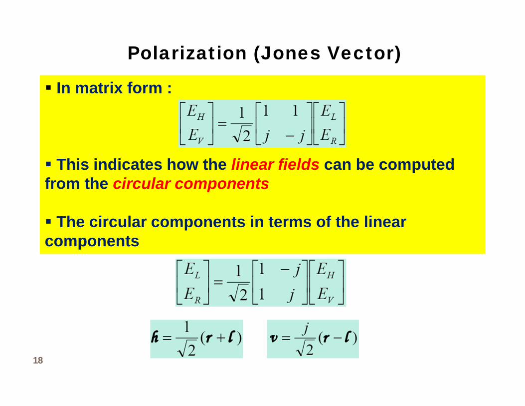
In matrix form :
This indicates how the linear fields can be computed from the circular components
The circular components in terms of the linear components

Polarization (Jones Vector)
19
A horizontal polarized wave is made up of right and leftcircularly polarized waves starting in phase (and contra-rotating)
A vertical polarized wave is made up of the two contra-rotating starting in anti-phase
The j is a time phase term common to both components advancing them by 900

Polarization (Stokes Vector)
20
Stokes parameters provide a very convenient means to describe the power density relationships in an EM wave in radar
For a single frequency signal (monochromatic) Stokes parameters are defined as

Polarization (Stokes Vector)
21
S0 The amplitude squared or intensity of the actual field vector. It is directly proportional to the power density being carried by the wave
S1 This indicates whether the wave is more horizontally than vertically polarized
S2 & S3 Indicate the ellipticity of the wave’s polarization
If we have linear polarization and S3=0 If S2=0 and the polarization ellipse will aligned vertically or horizontally It will be circular if the magnitudes of the vertical and horizontal components are also equal
0090

Polarization (Stokes Vector)
22
Complex phasorrepresentation
Representation in terms of principle angles of the polarization ellipse
Relative phase representation

Polarization (Stokes Vector)
23
The Stokes vector can be represented in different forms represented as:
Coherency vector

Polarization (Stokes Vector)Question ?
24
Is the absolute phase ( ) or ( ) preserved in Stokes vector representation of waves ?
x
y

Polarization (Stokes Vector)Quasi-monochromatic and Partially polarized waves
25
In Synthetic Aperture Radar (SAR) remote sensing the wave is transmitted in a narrowband
The transmitted and received waves are narrowband about the central frequency
The wave may still be interpreted as a plane wave is said to be quasi-monochromatic

Polarization (Stokes Vector)Quasi-monochromatic and Partially polarized waves
26
The components and of the real vector is
Mean frequency
Mean wave vector
Slowly varying in comparison with the periodic term
1E
2E )(E
))(cos()(),())(cos()(),(
tzkttatzEtzkttatzE
yyy
xxx
k
)(),(),(),( tttatayxyx
)exp( tj

Polarization (Stokes Vector)Quasi-monochromatic and Partially polarized waves
27
The receiving antenna measures the target scattered narrowband wave during an interval of time (Azimuth integration time)
If
The wave then behaves in the time interval like a monochromatic wave with mean frequency
The Jones vector or the Stokes vector can be used to characterize the polarization of the monochromatic wave that is said to be a completely polarized wave
T
constant Assumed and
time coherenceTarget
)(),(),(),( tttata
T
yxyx
T

Polarization (Stokes Vector)Quasi-monochromatic and Partially polarized waves
28
For a longer time interval the Electric field components and the phases are time varying
Wave is partially polarized
In this case the parameters that characterizes the polarization wave should be time averaged
The correlation between the time Electric field components is necessary to characterize partially polarized waves Coherency matrix measurement
Tyx
aa ,yx
,
conditionsergodic andty stationarisense - widesignal of conditionthe Under ?

Polarization (Stokes Vector)Quasi-monochromatic and Partially polarized waves
29
The coherency matrix is an interesting tool that permits observable parameters of a partially polarized wave to be measured
To deal with observables quantities, 2 quadratic forms of the quadratic products of 푬 and 푬∗푻 are considered
Time averaged total intensity 푬∗푻.푬
Coherency (2x2) Hermitian matrix 푱 = 푬.푬∗푻
… Ensemble average ?

Polarization (Stokes Vector)Quasi-monochromatic and Partially polarized waves
30
푱 is Hermitian positive semi-definite Real non-negative eigenvalues
The fact that 푱 = 푱 ∗푻 makes 푱 an observable quantity
The trace 풔ퟎ of the matrix 푱 is the total intensity of the wave
The coherency matrix 푱 is equivalent to the density matrix of Von Neuman that is widely used in Quantum Mechanics
푠 = ‖E‖ = 푡푟푎푐푒 퐽

Polarization (Stokes Vector)Quasi-monochromatic and Partially polarized waves
31
The four elements of the coherency matrix 푱 are uniquely associated with the wave
The unique set is intimately related to the appropriate degree of the Electric fields in the two orthogonal direction

Polarization (Stokes Vector)Quasi-monochromatic and Partially polarized waves
32
If the axes 풙,풚 are rotated about the direction of propagation the coherency matrix changes
However, the determinant 푱 of 푱 , the two real non-negative eigenvalues 흀ퟏ and 흀ퟐ, as well as the trace of the Hermitian coherency matrix 푱 remains rotation invariant
Combination of these entities leads to rotation invariant parameter of the wave Degree of Polarization (DOP)

Polarization (Stokes Vector)Quasi-monochromatic and Partially polarized waves
33
The rotation invariant parameter DOP has a physical significance
The wave is considered to be completely polarized if 푱 = ퟎ ⇒ 푫푶푷 = ퟏ
The wave is said to be completely unpolarized if the intensity of its components in any direction perpendicular to the direction of propagation is a constant ⇒ 푱 풊풔풅풊풂품풐풏풂풍풂풏풅풕풉풆풆풍풎풆풏풕풔풂풓풆풊풅풆풏풕풊풄풂풍 ⇒푫푶푷 = ퟎ

Polarization (Stokes Vector)Quasi-monochromatic and Partially polarized waves
34
A partially polarized wave can also be related to the elements of the coherency matrix
There is a one-to-one correspondence between the coherency matrix and the Stokes vector

Polarization (Stokes Vector)Quasi-monochromatic and Partially polarized waves
35
Radar energy backscattered from landscape will often be polarized
If the scattering is from random scattering media or time-varying scatterers the wave will be either partially polarized or completely unpolarized
For a totally unpolarized wave the two amplitudes fluctuates randomly without any relationship between them Amplitude variation is uncorrelated
The relative phase between the components would be totally random

Polarization (Stokes Vector)Quasi-monochromatic and Partially polarized waves
36
If the two orthogonal components (say H and V) are totally random such that there is no preferred polarization
⇒ 풂푯ퟐ = 풂푽ퟐ ⇒ 풔ퟎ = ퟐ 풂푯ퟐ풔ퟏ = ퟎ
풔ퟐ = 풔ퟑ = ퟎ(푻풉풆풕풊풎풆풂풗풆풓풂품풆풐풇풕풉풆풕풓풊품풐풏풐풎풆풕풓풊풄풇풖풏풄풕풊풐풏
풐풇풂풓풂풏풅풐풎풍풚풗풂풓풚풊풏품풂풏품풍풆풘풊풍풍풃풆풛풆풓풐)
풔풖풏풑풐풍 =2 푎
000

Polarization (Stokes Vector)Quasi-monochromatic and Partially polarized waves
37
Partially polarized wave results from the addition of unpolarized and polarized component
풔풑풐풍=푠푠푠푠
풂풏풅풔풖풏풑풐풍 =푠
000
풔푻풐풕풂풍 =푠 + 푠
푠푠푠
=푠푠푠푠
푠 = 푠 + 푠 + 푠

Polarization (Stokes Vector)Quasi-monochromatic and Partially polarized waves
38
Degree of polarization (DOP)
푫푶푷 =푷풐풘풆풓풅풆풏풔풊풕풚풐풇풕풉풆풑풐풍풂풓풊풛풆풅풑풂풓풕
푻풐풕풂풍풑풐풘풆풓풅풆풏풔풊풕풚
푫푶푷 = 푠
푠 + 푠=
푠 + 푠 + 푠푠

Polarization (Stokes Vector)Poincare Sphere Representation
39
A very interesting geometric representation of the Stokes parameters and the state of polarization of a wave emerges from
Equation of a sphere in the coordinate space 321
,, sss

Polarization (Stokes Vector)Poincare Sphere Representation
40
The sphere has radius of and its surface is the locus of all possible polarization states.
The polarization of a wave can be described by the amplitudes of its two orthogonal components and and their relative phase
The polarization of a wave can alternatively be also described by the angles of the polarization ellipse and
and the wave intensity
0s
Ha
Va
0s

Polarization (Stokes Vector)Poincare Sphere Representation
41

Polarization (Stokes Vector)Poincare Sphere Representation
42

Polarization (Stokes Vector)Poincare Sphere Representation
43
For partially polarized wave the point lies inside the sphere
The origin represents the case of unpolarized radiation


