The Electromechanical Arcade Alvaro E. Gil, Nicanor Quijano, and Kevin M. Passino Dept. Electrical and Computer Engineering The Ohio State University 2015 Neil Avenue, Columbus, OH 43210 April 5, 2004 Abstract This document provides a general guide for students who want to implement real-time scheduling strategies for the electromechanical arcade. This inexpensive experiment is designed to be a testbed for the implementation and evaluation of networked decentralized scheduling strategies. In this document, we describe the apparatus, its main components, the challenges that we need to face, and we show how to interface dSPACE with the experiment. Contents 1 Introduction 2 2 dSPACE: Hardware and Software 2 3 Experimental Apparatus and Challenges 2 3.1 Experiment Layout ..................................... 4 3.2 Guns ............................................. 4 3.3 Targets ........................................... 5 3.4 Lasers ............................................ 5 3.4.1 Lasers in Targets .................................. 5 3.4.2 Lasers in Guns ................................... 5 3.5 Photodetectors ....................................... 5 3.5.1 Photodetectors in Targets ............................. 6 3.5.2 Photodetectors in Guns .............................. 6 3.6 Motors ............................................ 6 3.7 Power Supply ........................................ 10 3.8 Travel Times Between Targets ............................... 11 3.9 Simulink Blocks ....................................... 12 3.9.1 Initialization and Control Algorithm ....................... 12 3.9.2 PID Control .................................... 14 3.9.3 Detection and Shooting at Targets ........................ 14 3.9.4 Shot Target ..................................... 15 3.10 Steps to Start and Stop the Experiment ......................... 15 3.10.1 How to Start the Experiment ........................... 15 3.10.2 How to Stop the Experiment ........................... 16 1
Transcript
The Electromechanical Arcade
Alvaro E. Gil, Nicanor Quijano, and Kevin M. PassinoDept. Electrical and Computer Engineering
The Ohio State University2015 Neil Avenue, Columbus, OH 43210
April 5, 2004
Abstract
This document provides a general guide for students who want to implement real-timescheduling strategies for the electromechanical arcade. This inexpensive experiment is designedto be a testbed for the implementation and evaluation of networked decentralized schedulingstrategies. In this document, we describe the apparatus, its main components, the challengesthat we need to face, and we show how to interface dSPACE with the experiment.
The ubiquitous presence of networked computing is significantly impacting the field of controlsystems. There are already many “distributed control systems” (DCS) in industry and significantcurrent research on networked multi-agent systems. These networked control systems are typicallydecentralized, large-scale, may be hierarchical, and are often quite complicated from a dynamicalsystems perspective. They typically have a blend of significant nonlinearities, nondeterministicbehavior, random delays, constrained information flow (e.g., only via the topology defined bythe communication network), high-dimensionality, etc. Since their main purpose is control ofa dynamical system they contain many (if not all) of the challenges typically found in controlsystems (e.g., disturbance rejection, tracking, robustness), and additional challenges due to thepresence of a computer network that synergistically interacts with the dynamical system. Theyrepresent a significant departure from typical, say classical DC motor control or inverted pendulumcontrol problems, and demand many of the same tools/skills and more such as expertise in softwareengineering, object-oriented programming, or real-time operating systems. Moreover, they demandthat more attention be given to a number of other nontraditional control objectives, includingdynamic resource allocation, scheduling of tasks, and control over large networks, than in the past.
The electromechanical arcade was designed to provide a testbed for distributed networkedscheduling strategies. Compared to past experiments, it provides opportunities to study coop-eration between two control systems.
2 dSPACE: Hardware and Software
We use dSPACE hardware and software for the arcade experiment. The dSPACE software is basedon Matlab/Simulink. To develop the block diagrams in Simulink for the arcade we use severalprocesses that (i) acquire the data and store this information in some global variables, (ii) makedecisions concerning the control, and (iii) update the digital/analog outputs.
In the combined dSPACE-Matlab package we have Simulink and the graphical user interface(GUI) that is provided in dSPACE. In Simulink we develop the controller and all the necessaryfunctions to run the experiment. Once we have the code, that they call the “model,” we compileit and following some steps that are transparent to the user, we obtain a file that will run thecode in real time, and provide the ability to set up a user interface. This GUI in dSPACE can beviewed as a diagnostic tool, since we can change some variables, and we can see in real time someof the variables defined by the user in the model. The students can find a tutorial introductionto dSPACE at http://www.ece.osu.edu/˜passino/dSPACEtutorial.doc.pdf. Below, we describe theapparatus, highlight the challenges it presents, and we explain the main Simulink blocks that canbe used to implement complex control strategies.
3 Experimental Apparatus and Challenges
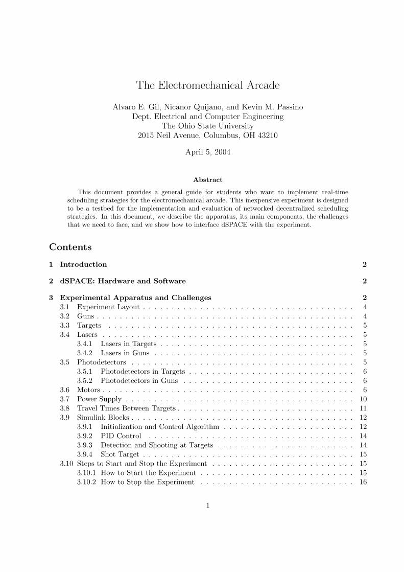
This experiment is composed of two main devices: guns and targets as shown in Figure 1. Eachof them is provided with a laser and a photodetector. There are in total eight “pop-up” targetsthat “appear” (indicated by its laser being on) and “disappear” (laser off) at frequencies that areindependent of each other (driven by simple timing circuits that can be adjusted by hand to providedifferent frequencies). The guns can detect a target appearance if its is pointed directly at it (it hasno “peripheral vision”) via a photodetector mounted on the gun. The two guns are each mountedon the shaft of a motor. Each of these motors has a quadrature encoder that provides the current
2
angular position of the motor. We use a PID controller to point any gun to the target that needsto be shot and these PID loops are well tuned so their performance will not impact the schedulingstrategies. The photodetectors of all targets (8 digital inputs), the laser and photodetector of eachgun (2 digital inputs and 2 digital outputs), the motor encoder, the output of each PID controller(1 analog output each) are connected to one DS1104 dSPACE card. All the lasers located at the
Gun 1Gun 2
Guns firing targets
Target 1
Motion control
amplifier for
motor 1
Motor 1Motion control
amplifier for
motor 2Motor 2
Laser 1
of target 4
Laser 2
of target 4
Photodetector
of target 7
Laser
of gun 2Photodetector
of gun 1
Figure 1: Electromechanical arcade experiment.
targets point to the gun photodetector and if one gun is pointing to a target when it appears, thisgun can shoot (turn its laser on) at that target, which triggers the corresponding photodetector ofthe shot target. When the photodetector of a target is triggered, the gun considers that specifictarget as “hit” (it gets a point for hitting it) and then the gun will look for the appearance ofanother target (the target depends on the scheduling strategies implemented by the students). Theanalogy with arcade games should be clear.
We assume that the guns do not know any information about the rate of appearance of alltargets (but one could invent strategies for estimating appearance sequences); however, the gunsdo know a priori the position of all targets, and the guns can communicate to each other theirdecisions about the targets that they are currently processing or pursuing. The challenges for thisexperiment are as follows:
1. To schedule in real-time a sequence of shootings so as to maximize the number of pointsthe team gets. Since target detecting and shooting requires movement of the guns a goodschedule will typically minimize the motion of the guns in maximizing point gain. Feedbackis required to overcome, for instance, uncertainty about when targets appear (i.e., open-loopprecomputed schedules will not be effective).
2. To cooperatively schedule the shooting of the guns in the presence of an imperfect communi-cation network that allows communication between the two guns. While the network couldbe the internet and a computer could be dedicated to each gun it can also be simulated withinone computer. Communication imperfections such as random but bounded delays, bandwidthconstraints or message misordering could be considered.
We consider then an “environment” that is highly uncertain (e.g., uncertain target appearancetimes) and where we have imperfect communications that make it difficult for the two guns to
3
coordinate their actions. Due to the presence of so much uncertainty it is generally not possibleto accurately predict far into the future, and hence generally not useful to employ optimizationapproaches to develop long sequences of planned operations either off- or on-line. Note that thisdecentralized scheduling problem can be thought of as a type of resource allocation strategy. Wehave implemented in the same computer a routine that simulates a communication network betweenthe two guns where random but bounded communication delays can be generated every time thetwo guns need to communicate to each other.
3.1 Experiment Layout
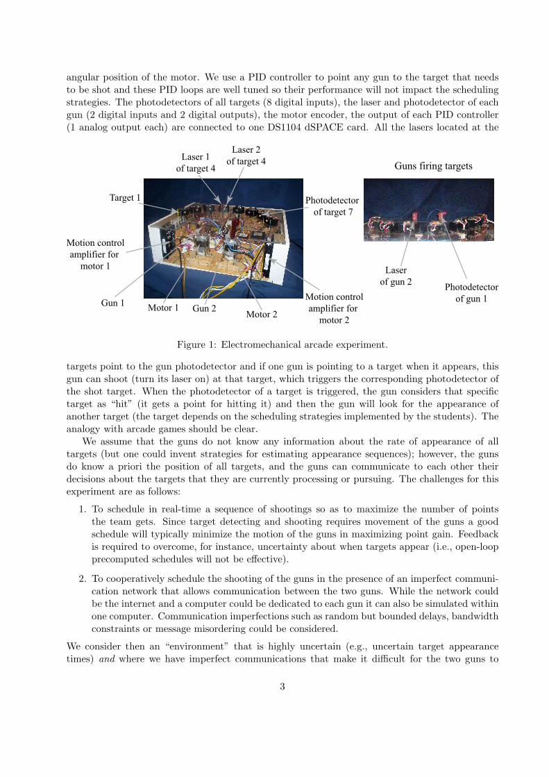
The housing of the experiment contains all devices and encloses the wiring. The base and sidesof the housing are constructed out of chipboard and have dimensions of 17.25 × 9 × 6.5 inches.A thin layer of Plexiglas is used as a lid to make the circuitry of the experiment visible from thetop. Figure 2 shows the location of the circuitry used in the experiment, which is grouped in partsdesignated by the letters A, B, C, and D in the figure.
Circuitry
A
Circuitry
B
Circuitry
D
Circuitry
C
Figure 2: Circuitry of electromechanical arcade experiment.
3.2 Guns
There are two guns in the experiment. Each gun is mounted on the shaft of a motor and providedwith one laser (Radio Shack # 277-1101) and one photodetector (Radio Shack # 276-1657). Afabric composite material is used for the guns which includes drilled holes to the size of the shaftthat keeps the guns in place with setscrews having a rubber tip to prevent movement and damage tothe shaft. Two holes were drilled through the top in order to fit the laser and detector in a mannerthat two targets lasers would be unable to shoot at each individual gun detector at the same time.It also allowed the positions of the laser and detector to remain unchanged with respect to thehorizontal axis. The vertical position can be altered with the set screws upon initial calibration.
Precautions: There are several precautions that must be taken before running the experiment.First, the fabric composite material that contains the guns must be mounted on the shaft of the
4
motors after the program is running in the DS1104 card; otherwise, the motor will move in a rapidmanner when the run button is hit in the GUI. This could cause damage to the wiring of the laserand photodetectors of the guns. Second, if the fabric composite material is already mounted onthe motors and you want to compile the Simulink program again, then you have to take out thefabric composite material first before compiling the program; otherwise, the wiring could also bedamaged.
3.3 Targets
The targets consist of eight photodetectors and sixteen lasers (two lasers per target). Black plasticboxes were screwed into the Plexiglas in an arc shape so that each target is at a significantlydifferent angle to the motor. Holes were made in the black boxes to insert the photodetectorswhile the lasers were fastened to the top of the black boxes at angles that were positioned to shootdirectly at its corresponding gun detector.
3.4 Lasers
As mentioned above, lasers are present in the targets and guns. The frequency and duty cycleof the target lasers are generated by mean of timers. The on-off gun laser signal is generated indSPACE.
3.4.1 Lasers in Targets
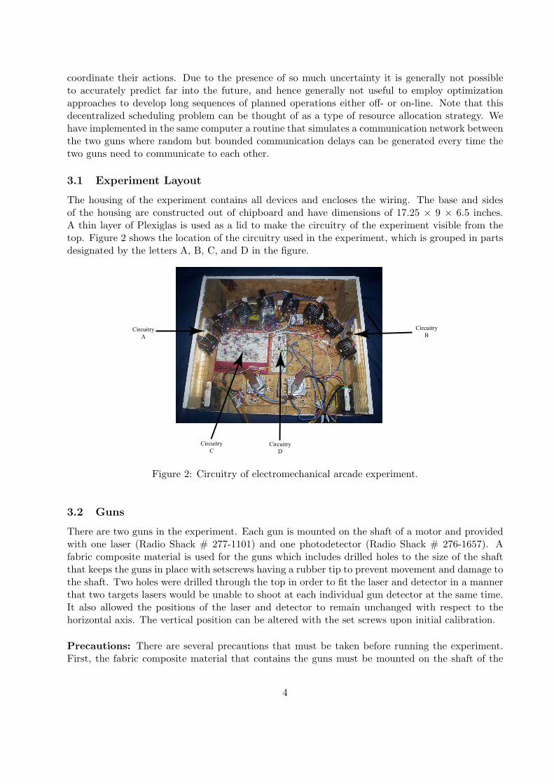
The LM555 timer sets up the frequency and duration of the target lasers. Figure 3(a) shows theLM555 circuit diagram while Figure 3(b) shows its circuit timing diagram. Both the frequencyf and duty cycle Dcyc can be manually adjusted by changing the parameters in the followingequations
f =1.44
(RA + 2RB)C=
1t1 + t2
Dcyc =RB
RA + 2RB=
t1t1 + t2
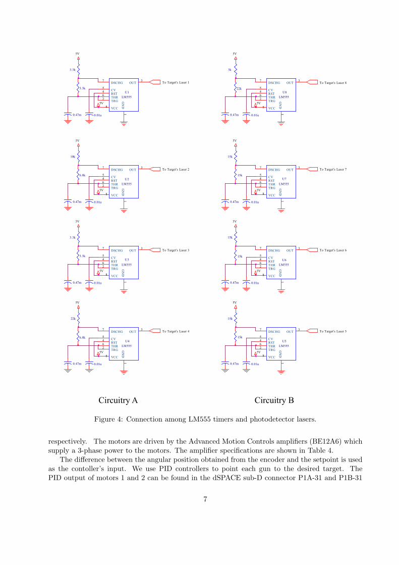
The output of the LM555 timers is connected to the positive terminal of the lasers as shown inFigure 4. Table 1 shows the key components found in the LM555 timer for each target.
3.4.2 Lasers in Guns
The lasers connected to the motors are controlled by an on-off signal generated in dSPACE. Theseoutputs can be located at sub-D connector P1B-11 and P1B-44 for motors 1 and 2 respectively.Figure 5 shows the connections between dSPACE and the gun laser drivers DS2003.
3.5 Photodetectors
These devices transform the light coming from the lasers to voltage signals by using voltage dividers.When the light intake is low, the voltage divider outputs a high value that is converted by thedSPACE card to 1. When the light intake is high, the voltage divider outputs a low value that isconverted to 0.
5
a. Circuit connection
b. Waveform
t1
t2
t1
Ra
C
Output
5V
U1
LM555
3
4
1
5
26
7OUT
RST
VCC
GN
D
CV
TRGTHR
DSCHG
8
Rb
0.01u
5V
time (sec.)
Volts
Figure 3: LM555 circuit and timing diagram.
3.5.1 Photodetectors in Targets
The dSPACE digital inputs used to monitor the status of the target photodetectors 1-8, as well asthe circuitry associated with the photodetectors, are shown in Figure 6. All these signals are usedby the dPSACE program in order to detect whether a target has been shot by any gun.
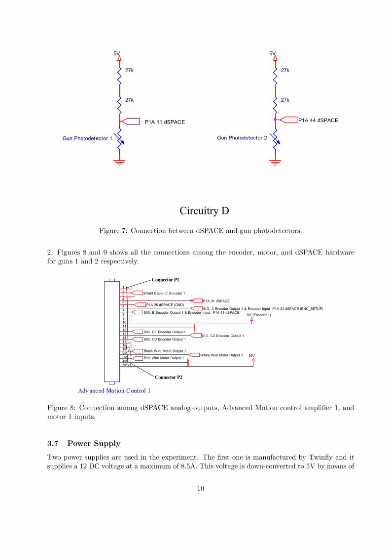
3.5.2 Photodetectors in Guns
The dSPACE digital inputs used to monitor the status of gun photodetectors 1 and 2 in the sub-Dconnector are P1A-11 and P1A-44, respectively. Figure 7 shows all these connections. These signalsare used by the dSPACE program in order to detect the appearance of a target when either gun iscurrent pointing at it.
3.6 Motors
Two inner rotor type 4 pole servo motors (Shinano Kenshi # LA052-040E4N02) are attached tothe base of the housing using four screws per motor. The two motors are centered ten inches apart,allowing equal spacing for shooting and each of them is provided with an encoder. The angularposition of the motors is obtained from its built-in encoder, which has a resolution of 500 pulsesper revolution. The specifications of both the motor and the encoder are shown in Tables 2 and 3
6
3.3k
0.47m
To Target's Laser 1
5V
U1
LM555
3
4
1
5
26
7OUT
RST
VCC
GN
D
CV
TRGTHR
DSCHG
8
3.3k
0.01u
5V
5V
5V
0.01u0.47m
8
To Target's Laser 4
U4
LM555
3
4
1
5
26
7OUT
RST
VCC
GN
D
CV
TRGTHR
DSCHG
6.8k
22k
To Target's Laser 3
3.3kU3
LM555
3
4
1
5
26
7OUT
RST
VCCG
ND
CV
TRGTHR
DSCHG
5V
85V
3.3k
0.47m 0.01u
6.8k
10k
5V
0.01u
8
U2
LM555
3
4
1
5
26
7OUT
RST
VCC
GN
D
CV
TRGTHR
DSCHG
5V
To Target's Laser 2
0.47m
5V
15k
8
To Target's Laser 5
0.47m
5V
0.01u
U5
LM555
3
4
1
5
26
7OUT
RST
VCC
GN
D
CV
TRGTHR
DSCHG
15k
To Target's Laser 6
15kU6
LM555
3
4
1
5
26
7OUT
RST
VCC
GN
D
CV
TRGTHR
DSCHG
0.47m
5V
5V
0.01u
8
15k
22k
To Target's Laser 8
0.01u0.47m
8
5V
U8
LM555
3
4
1
5
26
7OUT
RST
VCC
GN
D
CV
TRGTHR
DSCHG
3k
5V
0.47m
15k
To Target's Laser 7
5V
U7
LM555
3
4
1
5
26
7OUT
RST
VCC
GN
D
CV
TRGTHR
DSCHG
8
0.01u
15k
5V
Circuitry A Circuitry B
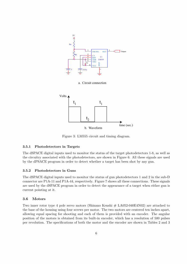
Figure 4: Connection among LM555 timers and photodetector lasers.
respectively. The motors are driven by the Advanced Motion Controls amplifiers (BE12A6) whichsupply a 3-phase power to the motors. The amplifier specifications are shown in Table 4.
The difference between the angular position obtained from the encoder and the setpoint is usedas the contoller’s input. We use PID controllers to point each gun to the desired target. ThePID output of motors 1 and 2 can be found in the dSPACE sub-D connector P1A-31 and P1B-31
Figure 5: Connection between dSPACE and gun laser drivers.
P1B 10 dSPACEP1A 26 dSPACE
Photoresistor 5
27k
P1B 27 dSPACE
27k
Photoresistor 7
27k
27k
27k
P1B 43 dSPACE
5V
27k
Photodetector 1
P1A 43 dSPACE
27k
Photodetecor 4
27k
27k
27k
5V5V
P1A 10 dSPACE
27k
Photoresistor 6
27k
5V
Photodetector 2
5V
Photodetector 8
5V
27k
5V
P1A 27 dSPACE
27k
27k
27k
5V
Photodetector 3
P1B 26 dSPACE
Circuitry C
Figure 6: Connection between dSPACE digital input and photodetector circuit.
respectively. These two analog outputs are connected to pins 4 and 5 of the connector P1 of theAdvanced Motion Control amplifiers whose outputs are connected to the coils of the motors 1 and
9
Circuitry D
27k
5V
27k
P1A 11 dSPACE
Gun Photodetector 1
27k
Gun Photodetector 2
P1A 44 dSPACE
27k
5V
Figure 7: Connection between dSPACE and gun photodetectors.
2. Figures 8 and 9 shows all the connections among the encoder, motor, and dSPACE hardwarefor guns 1 and 2 respectively.
5V (Encoder 1)
SIG. C3 Encoder Output 1
Adv anced Motion Control 1
1
3
5
7
9
11
13
15
1M
3M
5M
2
4
6
8
10
12
14
16
2M
4M
P1A 25 dSPACE (GND)
Connector P1
P1A 31 dSPACE
SIG. C2 Encoder Output 1
SIG. B Encoder Output 1 & Encoder Input P1A 41 dSPACE
Red Wire Motor Output 1
SIG. C1 Encoder Output 1
White Wire Motor Output 1
Connector P2
Black Wire Motor Output 1
Shield Cable of Encoder 1
36V
SIG. A Encoder Output 1 & Encoder Input P1A 24 dSPACE (ENC_SETUP)
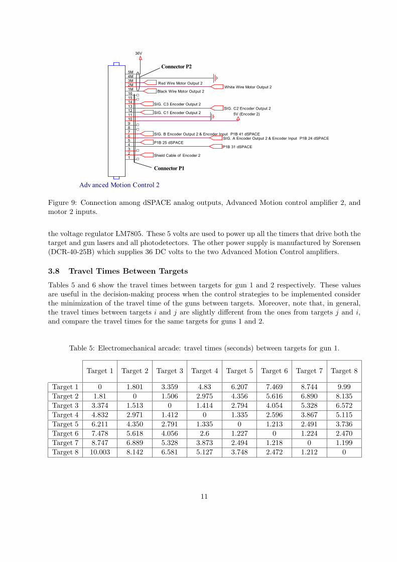
Figure 8: Connection among dSPACE analog outputs, Advanced Motion control amplifier 1, andmotor 1 inputs.
3.7 Power Supply
Two power supplies are used in the experiment. The first one is manufactured by Twinfly and itsupplies a 12 DC voltage at a maximum of 8.5A. This voltage is down-converted to 5V by means of
10
Red Wire Motor Output 2
SIG. C2 Encoder Output 2
Shield Cable of Encoder 2
SIG. A Encoder Output 2 & Encoder Input P1B 24 dSPACE
Black Wire Motor Output 2
SIG. B Encoder Output 2 & Encoder Input P1B 41 dSPACE
Adv anced Motion Control 2
5M
3M
1M
15
13
11
9
7
5
3
1
4M
2M
16
14
12
10
8
6
4
2
P1B 25 dSPACE
Connector P2
Connector P1
5V (Encoder 2)
36V
SIG. C3 Encoder Output 2
SIG. C1 Encoder Output 2
P1B 31 dSPACE
White Wire Motor Output 2
Figure 9: Connection among dSPACE analog outputs, Advanced Motion control amplifier 2, andmotor 2 inputs.
the voltage regulator LM7805. These 5 volts are used to power up all the timers that drive both thetarget and gun lasers and all photodetectors. The other power supply is manufactured by Sorensen(DCR-40-25B) which supplies 36 DC volts to the two Advanced Motion Control amplifiers.
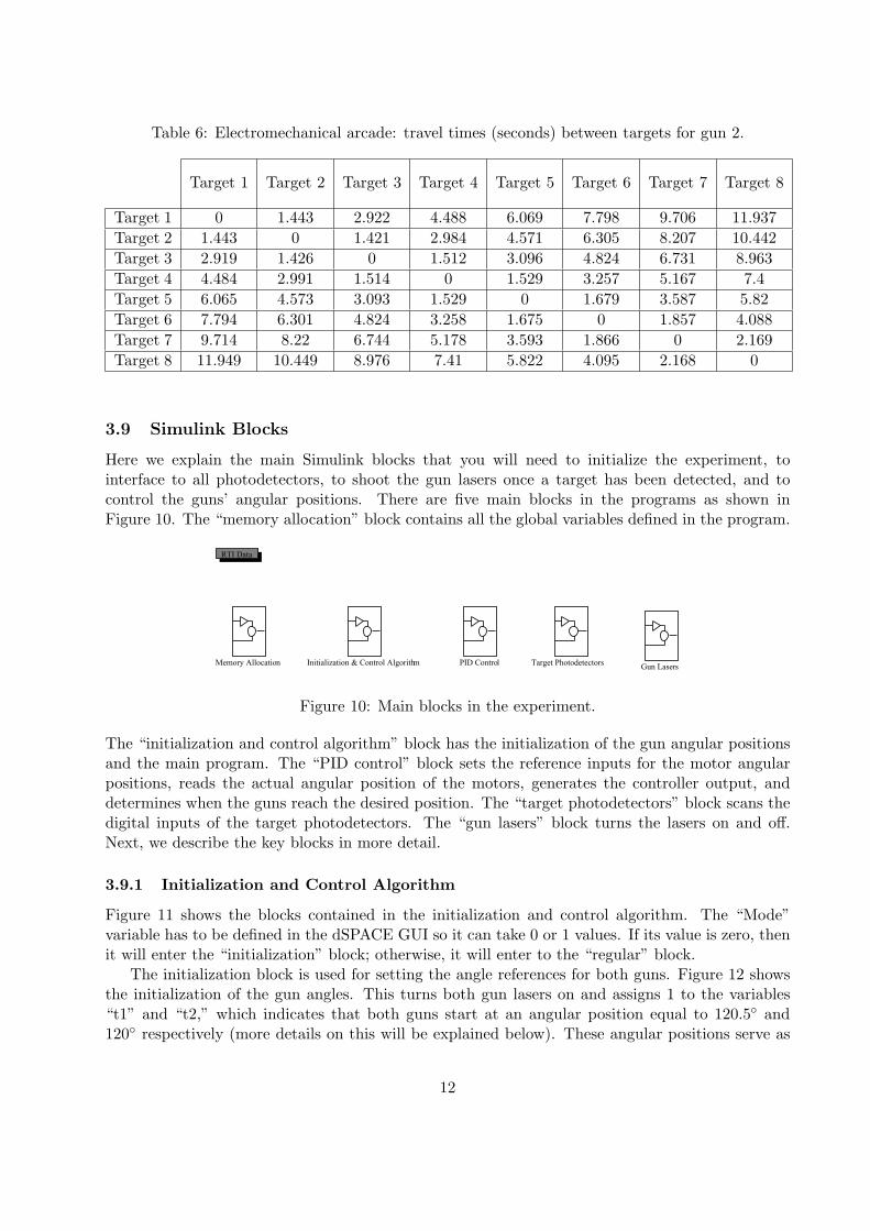
3.8 Travel Times Between Targets
Tables 5 and 6 show the travel times between targets for gun 1 and 2 respectively. These valuesare useful in the decision-making process when the control strategies to be implemented considerthe minimization of the travel time of the guns between targets. Moreover, note that, in general,the travel times between targets i and j are slightly different from the ones from targets j and i,and compare the travel times for the same targets for guns 1 and 2.
Table 5: Electromechanical arcade: travel times (seconds) between targets for gun 1.
Here we explain the main Simulink blocks that you will need to initialize the experiment, tointerface to all photodetectors, to shoot the gun lasers once a target has been detected, and tocontrol the guns’ angular positions. There are five main blocks in the programs as shown inFigure 10. The “memory allocation” block contains all the global variables defined in the program.
Target Photodetectors
RTI Data
PID ControlMemory Allocation Initialization & Control AlgorithmGun Lasers
Figure 10: Main blocks in the experiment.
The “initialization and control algorithm” block has the initialization of the gun angular positionsand the main program. The “PID control” block sets the reference inputs for the motor angularpositions, reads the actual angular position of the motors, generates the controller output, anddetermines when the guns reach the desired position. The “target photodetectors” block scans thedigital inputs of the target photodetectors. The “gun lasers” block turns the lasers on and off.Next, we describe the key blocks in more detail.
3.9.1 Initialization and Control Algorithm
Figure 11 shows the blocks contained in the initialization and control algorithm. The “Mode”variable has to be defined in the dSPACE GUI so it can take 0 or 1 values. If its value is zero, thenit will enter the “initialization” block; otherwise, it will enter to the “regular” block.
The initialization block is used for setting the angle references for both guns. Figure 12 showsthe initialization of the gun angles. This turns both gun lasers on and assigns 1 to the variables“t1” and “t2,” which indicates that both guns start at an angular position equal to 120.5 and120 respectively (more details on this will be explained below). These angular positions serve as
12
else
Regular
0
Modeif
Initialization
u1if(u1 == 0)
else
If1
Figure 11: Blocks contained in the initialization and control algorithm.
references for future desired angular positions so that you need to point both gun lasers at thephotodetector of target 1 at this time. Figure 13 shows the logic to check whether it is time to
GunLaser2
Data StoreWrite3
GunLaser1
Data StoreWrite2
t2
Data StoreWrite1
t1
Data StoreWrite
1
Constant 3
1
Constant 2
1
Constant 1
1
Constant
if
Action Port
Figure 12: Initialization of the experiment.
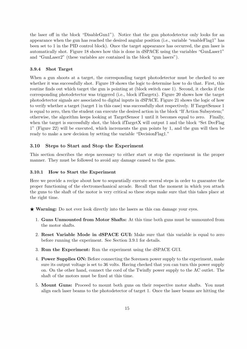
make a new decision. If so, then the variable “DecisionFlag1” is equal to 1 and the block “Chooset1” will select the new target to process next. You will implement your own scheduling algorithmsin this block, where the results of your solutions will dynamically change the values of the variablest1 and t2 to point the guns at the desired targets. Figure 14 shows one option of how the gunscan choose different targets at every decision time; however, the students still need to implementtheir own strategies in all the blocks “Apply Policy for Gun 1 if T2=X.” Here, the basic idea isthat gun 1 checks first which target gun 2 is pursuing or processing. Then gun 1 chooses any targetexcept the one already being pursued or processed by gun 2. Once a gun has chosen a new targetto process next, it will wait for the appearance of the target that is pointing at. If so, it will turnits laser on; otherwise, it will wait for the target appearance. Once the gun shoots at the target,the program checks if the target was shot successfully and if that is the case, the gun will gain a
13
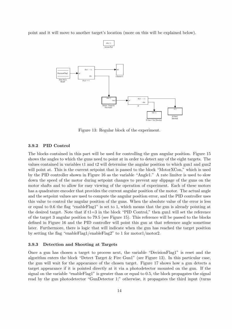
point and it will move to another target’s location (more on this will be explained below).
u1
if(u1 == 1)
else
If u1 == 1
else
If Gun 1 Not Shooted
if
If Gun 1Shooted
u1if(u1 == 1 )
else
If
else
Out2
Detect Target & Fire Gun1
DecisionFlag1
Data StoreRead1
In1
Choose t1
else
Action Port
Figure 13: Regular block of the experiment.
3.9.2 PID Control
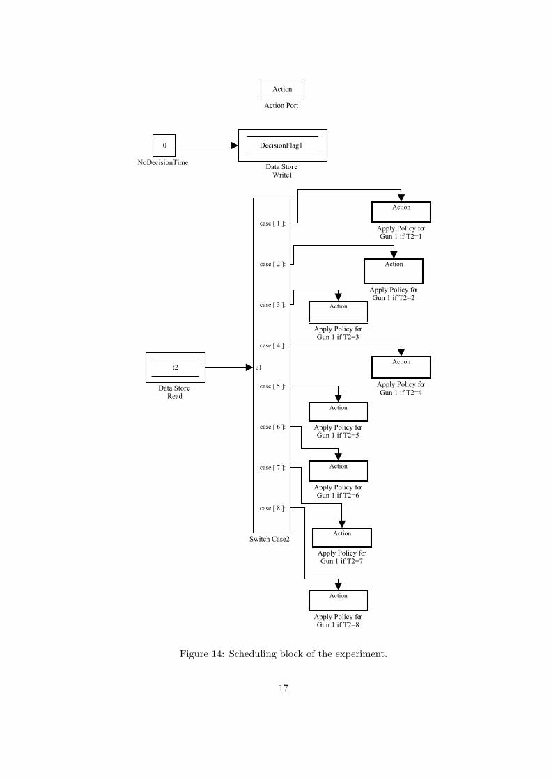
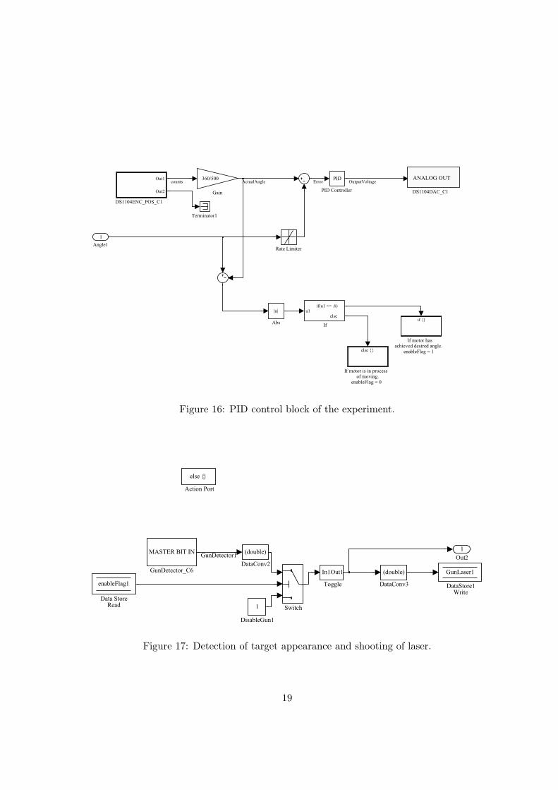
The blocks contained in this part will be used for controlling the gun angular position. Figure 15shows the angles to which the guns need to point at in order to detect any of the eight targets. Thevalues contained in variables t1 and t2 will determine the angular position to which gun1 and gun2will point at. This is the current setpoint that is passed to the block “MotorXCon,” which is usedby the PID controller shown in Figure 16 as the variable “Angle1.” A rate limiter is used to slowdown the speed of the motor during setpoint changes to prevent any slippage of the guns on themotor shafts and to allow for easy viewing of the operation of experiment. Each of these motorshas a quadrature encoder that provides the current angular position of the motor. The actual angleand the setpoint values are used to compute the angular position error, and the PID controller usesthis value to control the angular position of the guns. When the absolute value of the error is lessor equal to 0.6 the flag “enableFlag1” is set to 1, which means that the gun is already pointing atthe desired target. Note that if t1=3 in the block “PID Control,” then gun1 will set the referenceof the target 3 angular position to 79.5 (see Figure 15). This reference will be passed to the blocksdefined in Figure 16 and the PID controller will point this gun at that reference angle sometimelater. Furthermore, there is logic that will indicate when the gun has reached the target positionby setting the flag “enableFlag1/enableFlag2” to 1 for motor1/motor2.
3.9.3 Detection and Shooting at Targets
Once a gun has chosen a target to process next, the variable “DecisionFlag1” is reset and thealgorithm enters the block “Detect Target & Fire Gun1” (see Figure 13). In this particular case,the gun will wait for the appearance of the chosen target. Figure 17 shows how a gun detects atarget appearance if it is pointed directly at it via a photodetector mounted on the gun. If thesignal on the variable “enableFlag1” is greater than or equal to 0.5, the block propagates the signalread by the gun photodetector “GunDetector 1;” otherwise, it propagates the third input (turns
14
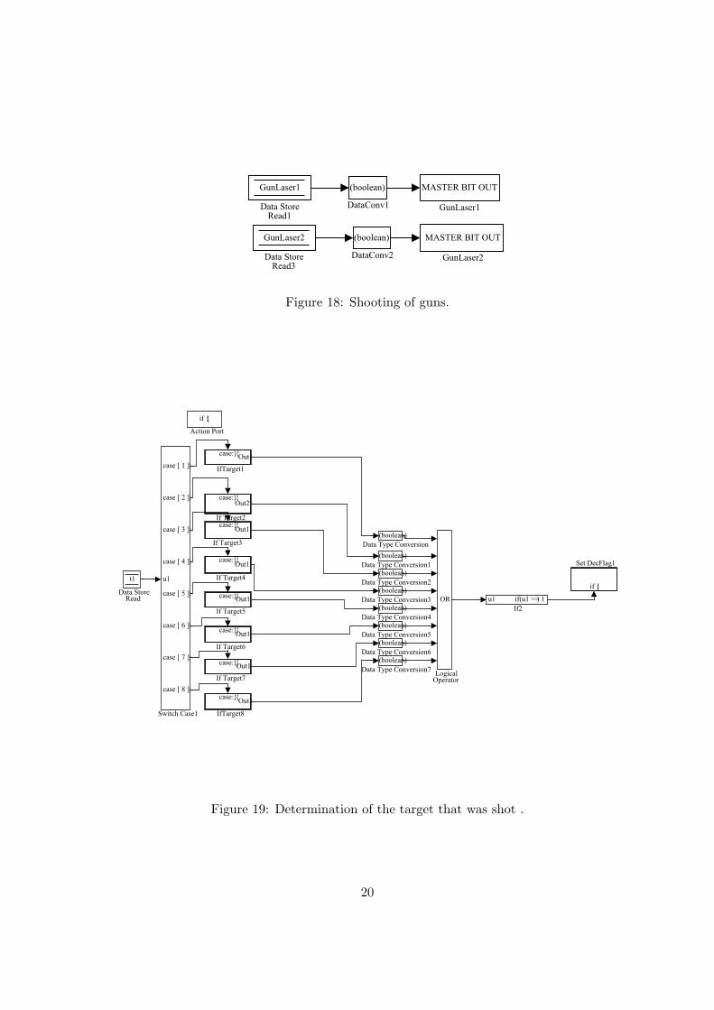
the laser off in the block “DisableGun1”). Notice that the gun photodetector only looks for anappearance when the gun has reached the desired angular position (i.e., variable “enableFlag1” hasbeen set to 1 in the PID control block). Once the target appearance has occurred, the gun laser isautomatically shot. Figure 18 shows how this is done in dSPACE using the variables “GunLaser1”and “GunLaser2” (these variables are contained in the block “gun lasers”).
3.9.4 Shot Target
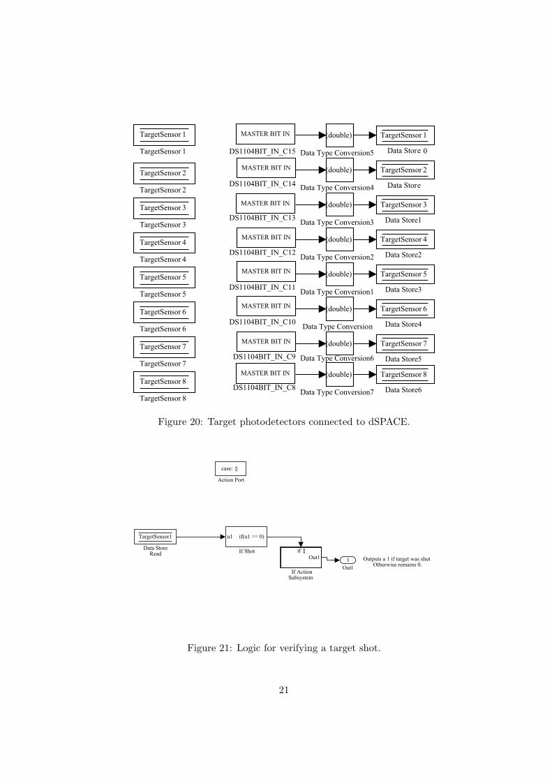
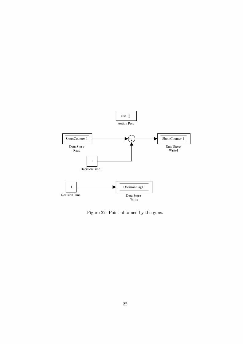
When a gun shoots at a target, the corresponding target photodetector must be checked to seewhether it was successfully shot. Figure 19 shows the logic to determine how to do that. First, thisroutine finds out which target the gun is pointing at (block switch case 1). Second, it checks if thecorresponding photodetector was triggered (i.e., block ifTargetx). Figure 20 shows how the targetphotodetector signals are associated to digital inputs in dSPACE. Figure 21 shows the logic of howto verify whether a target (target 1 in this case) was successfully shot respectively. If TargetSensor 1is equal to zero, then the student can execute the desired action in the block “If Action Subsystem;”otherwise, the algorithm keeps looking at TargetSensor 1 until it becomes equal to zero. Finally,when the target is successfully shot, the block ifTargetX will output 1 and the block “Set DecFlag1” (Figure 22) will be executed, which increments the gun points by 1, and the gun will then beready to make a new decision by setting the variable “DecisionFlag1.”
3.10 Steps to Start and Stop the Experiment
This section describes the steps necessary to either start or stop the experiment in the propermanner. They must be followed to avoid any damage caused to the guns.
3.10.1 How to Start the Experiment
Here we provide a recipe about how to sequentially execute several steps in order to guarantee theproper functioning of the electromechanical arcade. Recall that the moment in which you attachthe guns to the shaft of the motor is very critical so these steps make sure that this takes place atthe right time.
F Warning: Do not ever look directly into the lasers as this can damage your eyes.
1. Guns Unmounted from Motor Shafts: At this time both guns must be unmounted fromthe motor shafts.
2. Reset Variable Mode in dSPACE GUI: Make sure that this variable is equal to zerobefore running the experiment. See Section 3.9.1 for details.
3. Run the Experiment: Run the experiment using the dSPACE GUI.
4. Power Supplies ON: Before connecting the Sorensen power supply to the experiment, makesure its output voltage is set to 36 volts. Having checked that you can turn this power supplyon. On the other hand, connect the cord of the Twinfly power supply to the AC outlet. Theshaft of the motors must be fixed at this time.
5. Mount Guns: Proceed to mount both guns on their respective motor shafts. You mustalign each laser beams to the photodetector of target 1. Once the laser beams are hitting the
15
photodector of target 1, proceed to fix the guns to the motor shafts by means of the setscrewslocated in the fabric composite material.
6. Run your control strategy: At this moment you are ready to test your scheduling strategy.You can do this by setting the variable Mode to 1 in the dSPACE GUI.
F Warning: If you want to stop the experiment, you must follow the steps below.
3.10.2 How to Stop the Experiment
These are the steps that must be taken to stop the experiment. These steps avoid the potentialdamage that could be caused to the gun wires if these are not followed in the right order. Thesesteps must be followed when the program needs to be stopped when it is already running or whenyou need to recompile your Simulink file.
1. Reset Variable Mode in dSPACE GUI: Set this variable to zero. The guns will pointat target 1.
2. Unmount Guns: Proceed to take the guns off the motor shafts.
3. Experiment Ready: Now you can do what you need to do with the software. You canrecompile your file or stop the experiment in the dSPACE GUI.
F To start the experiment again follow the steps in the above subsection.
Acknowledgements: We would like to thank William Thalgott and Emmet Evans for helping withsome construction details for the electromechanical arcade. The arcade was originally constructedby a group of undergraduates in an EE 682P design project and it was later improved by KristinaGuspan and Dawn M. Kin.
16
u1
case [ 1 ]:
case [ 2 ]:
case [ 3 ]:
case [ 4 ]:
case [ 5 ]:
case [ 6 ]:
case [ 7 ]:
case [ 8 ]:
Switch Case2
0
NoDecisionTime
DecisionFlag1
Data StoreWrite1
t2
Data StoreRead
Action
Apply Policy forGun 1 if T2=8
Action
Apply Policy forGun 1 if T2=7
Action
Apply Policy forGun 1 if T2=6
Action
Apply Policy forGun 1 if T2=5
Action
Apply Policy forGun 1 if T2=4
Action
Apply Policy forGun 1 if T2=3
Action
Apply Policy forGun 1 if T2=2
Action
Apply Policy forGun 1 if T2=1
Action
Action Port
Figure 14: Scheduling block of the experiment.
17
0
Target8b
0.05
Target8
22.3
Target7b
15
Target7
41.5
Target6b
30.25
Target6
58.8
Target5b
45.45
Target5
74.6
Target4b
62
Target4
90.25
Target3b
79.5
Target3
105
Target2b
98.25
Target2
120
Target1b
120.5
Target1
MultiportSwitch1
MultiportSwitch
Angle2
Motor2Con
Angle1
Motor1Con
t2
Data StoreRead2
t1
Data StoreRead
AngleSP
Figure 15: Set-point of guns.
18
Terminator1
Rate Limiter
PID
PID Controller
else
If motor is in processof moving.
enableFlag = 0
if
If motor has achieved desired angle.
enableFlag = 1
u1if(u1 <= .6)
else
If
360/500
Gain
Out1
Out2
DS1104ENC_POS_C1
DS1104DAC_C1
|u|
Abs
1
Angle1
counts Error OutputVoltageActualAngleANALOG OUT
Figure 16: PID control block of the experiment.
1
Out2
In1Out1
Toggle
Switch
MASTER BIT IN
GunDetector_C6
1
DisableGun1
(double)
DataConv3
(double)
DataConv2
GunLaser1
DataStore1Write
enableFlag1
Data StoreRead
else
Action Port
GunDetector1
Figure 17: Detection of target appearance and shooting of laser.
19
MASTER BIT OUT
GunLaser1
MASTER BIT OUT
GunLaser2
(boolean)
DataConv2
(boolean)
DataConv1
GunLaser2
Data StoreRead3
GunLaser1
Data StoreRead1
Figure 18: Shooting of guns.
u1
case [ 1 ]:
case [ 2 ]:
case [ 3 ]:
case [ 4 ]:
case [ 5 ]:
case [ 6 ]:
case [ 7 ]:
case [ 8 ]:
Switch Case1
if
Set DecFlag1
OR
LogicalOperator
case: Out1
IfTarget8
case: Out1
IfTarget1
u1 if(u1 == 1 )
If2
case: Out1
If Target7
case: Out1
If Target6
case: Out1
If Target5
case: Out1
If Target4
case: Out1
If Target3
case: Out2
If Target2
(boolean)
Data Type Conversion7
(boolean)
Data Type Conversion6
(boolean)
Data Type Conversion5
(boolean)
Data Type Conversion4
(boolean)
Data Type Conversion3
(boolean)
Data Type Conversion2
(boolean)
Data Type Conversion1
(boolean)
Data Type Conversion
t1
Data StoreRead
if
Action Port
Figure 19: Determination of the target that was shot .
20
TargetSensor 8
TargetSensor 8
TargetSensor 7
TargetSensor 7
TargetSensor 6
TargetSensor 6
TargetSensor 5
TargetSensor 5
TargetSensor 4
TargetSensor 4
TargetSensor 3
TargetSensor 3
TargetSensor 2
TargetSensor 2
TargetSensor 1
TargetSensor 1
(double)
Data Type Conversion7
(double)
Data Type Conversion6
(double)
Data Type Conversion5
(double)
Data Type Conversion4
(double)
Data Type Conversion3
(double)
Data Type Conversion2
(double)
Data Type Conversion1
(double)
Data Type Conversion
TargetSensor 8
Data Store6
TargetSensor 7
Data Store5
TargetSensor 6
Data Store4
TargetSensor 5
Data Store3
TargetSensor 4
Data Store2
TargetSensor 3
Data Store1
TargetSensor 1
Data Store
TargetSensor 2
Data Store
DS1104BIT_IN_C9
DS1104BIT_IN_C8
DS1104BIT_IN_C15
DS1104BIT_IN_C14
DS1104BIT_IN_C13
DS1104BIT_IN_C12
DS1104BIT_IN_C11
DS1104BIT_IN_C10
MASTER BIT IN
MASTER BIT IN
MASTER BIT IN
MASTER BIT IN
MASTER BIT IN
MASTER BIT IN
MASTER BIT IN
MASTER BIT IN
0
Figure 20: Target photodetectors connected to dSPACE.
Outputs a 1 if target was shot.Otherwise remains 0.