THE ELECTRONIC FLIGHT BAG: A MULTI-FUNCTION TOOL FOR THE MODERN COCKPIT Major Fredric S. Fitzsimmons, USAFR August 2002 Institute for Information Technology Applications United States Air Force Academy, Colorado IITA Research Publication 2 Information Series
Transcript
THE ELECTRONIC FLIGHT BAG: A MULTI-FUNCTION TOOL
FOR THE MODERN COCKPIT
Major Fredric S. Fitzsimmons, USAFR
August 2002
Institute for Information Technology Applications United States Air Force Academy, Colorado
IITA Research Publication 2 Information Series
Report Documentation Page Form ApprovedOMB No. 0704-0188
Public reporting burden for the collection of information is estimated to average 1 hour per response, including the time for reviewing instructions, searching existing data sources, gathering andmaintaining the data needed, and completing and reviewing the collection of information. Send comments regarding this burden estimate or any other aspect of this collection of information,including suggestions for reducing this burden, to Washington Headquarters Services, Directorate for Information Operations and Reports, 1215 Jefferson Davis Highway, Suite 1204, ArlingtonVA 22202-4302. Respondents should be aware that notwithstanding any other provision of law, no person shall be subject to a penalty for failing to comply with a collection of information if itdoes not display a currently valid OMB control number.
1. REPORT DATE AUG 2002 2. REPORT TYPE
3. DATES COVERED 00-00-2002 to 00-00-2002
4. TITLE AND SUBTITLE The Electronic Flight Bag: A Multi-Function Tool for the ModernCockpit
5a. CONTRACT NUMBER
5b. GRANT NUMBER
5c. PROGRAM ELEMENT NUMBER
6. AUTHOR(S) 5d. PROJECT NUMBER
5e. TASK NUMBER
5f. WORK UNIT NUMBER
7. PERFORMING ORGANIZATION NAME(S) AND ADDRESS(ES) Institute for Information Technology Applications,USAFA/DFEI,2354Fairchild Drive,USAF Academy,CO,80840-6258
8. PERFORMING ORGANIZATIONREPORT NUMBER
9. SPONSORING/MONITORING AGENCY NAME(S) AND ADDRESS(ES) 10. SPONSOR/MONITOR’S ACRONYM(S)
11. SPONSOR/MONITOR’S REPORT NUMBER(S)
12. DISTRIBUTION/AVAILABILITY STATEMENT Approved for public release; distribution unlimited
13. SUPPLEMENTARY NOTES The original document contains color images.
14. ABSTRACT
15. SUBJECT TERMS
16. SECURITY CLASSIFICATION OF: 17. LIMITATION OF ABSTRACT
18. NUMBEROF PAGES
65
19a. NAME OFRESPONSIBLE PERSON
a. REPORT unclassified
b. ABSTRACT unclassified
c. THIS PAGE unclassified
Standard Form 298 (Rev. 8-98) Prescribed by ANSI Std Z39-18
ii
ABOUT THE AUTHOR Major Fredric S. Fitzsimmons is an Air Force Reserve Officer living in Fort Collins, Colorado. He is a primary duty Admissions Liaison Officer for the United States Air Force Academy and a part time researcher for the Academy’s Institute for Information Technology Applications. Major Fitzsimmons is a 1985 Summa Cum Laude graduate of the University of West Florida with a Bachelors Degree in Scientific Systems Science. He has also completed several Masters level courses through Embry-Riddle Aeronautical University including Aircraft and Spacecraft Development, Human Factors in the Aviation/Aerospace Industry, Aviation/Aerospace Accident Investigation and Safety Systems, and The Air Transportation System.
Major Fitzsimmons served over 14 years on active duty with the United States Air Force. A Senior Pilot, he amassed more than 3000 hours of flying time, with over 2800 hours in the A-10 attack aircraft. His many aerial accomplishments include 148 combat missions during Operations DESERT STORM and DENY FLIGHT. His jobs on active duty include the following: wing flight examiner, formal course A-10 instructor pilot, flight commander and assistant director of operations. Major Fitzsimmons is also familiar with the operations and procedures of a major airline, having served as a flight engineer on Boeing 727s for United Airlines. The views expressed in this paper are those of the author and do not necessarily reflect the official policy or position of the Institute for Information Technology Application, the Department of the Air Force, the Department of Defense or the U.S. Government.
___________________________________________________ Comments pertaining to this report are invited and should be directed to: Sharon Richardson Director of Conferences and Publication Institute for Information Technology Applications HQ USAFA/DFPS 2354 Fairchild Drive, Suite 6L16D USAF Academy CO 80840-6258 Tel. (719) 333-2746; Fax (719) 333-2945 Email: [email protected]
Appendix A Simulated Peacetime C-5 Cargo Mission ............................... ..54 Appendix B Simulated A-10 Combat Search and Rescue Mission…………57 About the Institute…………………………………………………………………60
iv
List of Tables Table 1 Comparison of differences and similarities of commercial products…....12 Table 2 Eleven Most Prominent Display Technologies in DoD Inventory by
Percentage……………………………………………………………….……21 Table 3 Specifications for Military Applications of Flat Panel Displays……… …23
List of Figures Figure 1 Sample page showing system considerations……………………….……..8 Figure 2 Electronic Flight Bag Classifications…………………………………...…..10 Figure 3 Fujitsu P600 Tablet PC………………………...……………………....……11 Figure 4 Northstar’s CT-1000G………………………….……………………….……13 Figure 5 Spirent System’s AvVantage™……………….……………………….……13 Figure 6 UPS Aviation Technologies Apollo MX-20…..……………………….……14 Figure 7 MX-20’s Chart View Display…………………..……………………….……14 Figure 8 Bendix/King KMD 850………………………….……………………….……15 Figure 9 Garmin GNS-530……………………………….……………………….……15 Figure 10 UASC’s UCD………………………………………………………………..…16 Figure 11 Rockwell Collins MFD-268P………………………………………….….…..16 Figure 12 Honeywell’s Primus Epic™ Cockpit Design ………………………..….…17 Figure 13 Examples of Primus Epic’s™ EAP and System Monitoring Screens……18 Figure 14 Sample VIA System Configuration. Shows input from TCAS and
SATCOM data links, internal flight management, navigation, displays and processor cards, and outputs to the autopilot, autothrottle and displays………………………………………….………….…………….……18
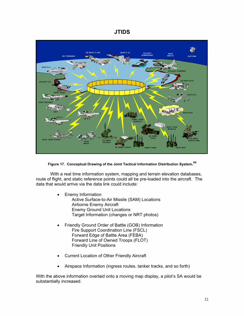
Figure 15 Honeywell DU-1080 Display……………………………….……..…….……19 Figure 16 Astronautics Corporation of America’s PID …………….………….……19 Figure 17 Conceptual Drawing -- Joint Tactical Information Distribution System.…32
v
ABSTRACT
This research is intended to inform the reader about Electronic Flight Bags (EFBs). After an explanation of an EFB, development history, a short discussion of human factors and products currently available in the aviation industry, the article discusses current and future display technologies—the heart of the Electronic Flight Bag. The article continues with many potential applications for EFBs for general aviation and specific military benefits. After reviewing some of the advantages and drawbacks to modifying cockpits to incorporate these devices, the author makes an argument for a cohesive joint effort during the design and implementation phases of EFBs. Finally conclusions and recommendations are offered. The appendices present two simulated flights to illustrate the potential of the Electronic Flight Bag, one describing a resupply mission by a cargo aircraft, and the other a combat mission in a tactical fighter.
THE ELECTRONIC FLIGHT BAG: A MULTI-FUNCTION TOOL FOR THE MODERN COCKPIT
INTRODUCTION Information technology has made great advances throughout industry and within the military, but this progression has been slow to make its way into the military cockpit. Due to the demanding environmental conditions in modern military cockpits, the lengthy certification and acquisition hurdles and the costs associated with the redesign of instrument panels, cockpit improvements have been few and very far between. Many cockpits still contain the original electromechanical (EM) gauges and cathode ray tubes (CRTs) that were part of the aircraft’s original design. No example of this is more glaring than that of the venerable B-52 which recently celebrated its 50th anniversary. Instead of making the decision to modernize our aircraft cockpits, the older, less reliable displays are replaced at a high cost. These costs are, more often than not, exacerbated by the vanishing vender syndrome (VVS)—the unfortunate syndrome that requires the replacement of a part that is no longer in production, either because the technology is too antiquated to market, or the company is no longer in business. In addition to the antiquated designs of many cockpits, another management challenge is the ever increasing amount of required paper documents in the cockpit. Ten years after the initiative of the Air Force Chief of Staff, General McPeak, to move toward a “paperless” Air Force, the military cockpit has been ignored in this modernization effort. Pilots still carry large quantities of paper to the aircraft that could, and in some respects already do, exist in an electronic form. A few examples include: Dash One/Dash One checklist (aircraft specific flight manual), weapons checklist, air refueling checklist, local area in-flight guides, instrument approach plates, enroute navigation charts, maps, and so forth. Not only must the pilot contend with finding a place to store these papers in the very limited space available, the currency of these documents constantly must be manually updated. The money spent on developing, producing, distributing and maintaining this documentation in a paper format varies from system to system, but in general, is quite high. Additionally, in most cases these products are initially developed in an electronic medium and much of the cost is in converting them to a paper medium. It would be more cost effective for the Air Force, and preferable to the pilots, to leave the information in an electronic format if only there were a device in the cockpit that could display it. The electronic flight bag (EFB), the focus of this study, can alleviate many of these problems. Unlike many technological improvements in the past that were initially developed by the military and utilized by the civilian sector (e.g. the global positioning system, GPS), EFBs offer the military an opportunity to take advantage of this ground breaking technology developed by the civilian sector. Due to the ease with which these devices can be integrated into less sophisticated airplanes, small general aviation (GA) aircraft have led the way. In an attempt to minimize the high costs associated with the procurement of paper documents for their pilots, many major commercial airlines have also begun to research the suitability of these devices. Notably, Northwest Airlines and United Air Lines (UAL) have tested simple EFBs in a pen-tablet form. The U. S. military should also attempt to take advantage of the vast capabilities these devices offer.
2
This paper will define the term electronic flight bag, and take the reader through the history of its development. Next, the paper will discuss some of the human factor considerations and review currently available commercial EFBs. Then it will delve into the vast applications available of these devices. Following an analysis of the pros and cons of retrofitting our fleets, the paper will make an argument for the importance of jointly implementing this technology. Finally, the paper offers conclusions and recommendations with regard to EFBs. I. WHAT IS AN ELECTRONIC FLIGHT BAG?
An electronic flight bag is an electronic version of a pilot’s flight bag. What then
is a flight bag? Simply stated, it is a physical device that carries the printed documentation pilots must have available to them during the course of the flight, such as flight manuals, operation manuals, and approach plates. This “bag” can range from a navigation briefcase used in large aircraft, to a smaller, soft sided publications bag used in fighter aircraft, to even a saddle bag that is laid across the glare shield of an A-10. In some fighters, the pockets of the g-suit are used to hold many of the publications—not the preferred placement for a safe ejection. On some larger aircraft, the majority of the publications are permanently stored onboard. For example, an MC-130H has a Technical Order (TO) library onboard that weighs 270 pounds1.
Having an electronic display replace the paper documents currently in use not only saves space and weight, but it also offers operational advantages. An electronic flight bag can become the ultimate situational awareness (SA) multiplier. As a high quality display, it can not only present words to the pilot, but pictures and graphics.
The Volpe National Transportation Systems Center (VOLPE Center), a human
factors research branch of the Department of Transportation, located in Cambridge, Massachusetts, defines an EFB as, “an electronic information management device for use by pilots in performing flight management tasks. It typically consists of a screen and controls in a self-contained unit that is relatively small, weighing only a few pounds at most. EFBs can store and display large amounts of data. Some existing EFBs run proprietary operating systems, but most are compatible with the Microsoft Windows® operating system.”2 This definition is tailored more toward GA aircraft and represents an entry level EFB.
Due to certification and safety oversight responsibilities, the Federal Aviation Administration (FAA) also has become involved in the certification of these devices. In the FAA’s Advisory Circular No: 120-EFB, electronic flight bags are defined as “Electronic computing and/or communications equipment or systems used to display a variety of aviation data or perform a variety of aviation functions. In the past some of these functions were traditionally accomplished using paper references. The scope of EFB functionality may include datalink connectivity. EFBs may be portable electronic devices or installed systems. The physical EFB display may use various technologies, formats, and forms of communication.”3 This definition is broader in scope than the VOLPE Center’s definition, and expands into two very important areas. It includes installed devices which could be both more sophisticated and complex, and it introduces datalink connectivity, a feature of EFBs that will undoubtedly prove to be very useful.
3
Another institution that has addressed the capabilities of electronic computing devices is the U.S. Air Force’s Material Command (AFMC). AFMC has developed a flight manual transformation program (FMTP) that initially studied digitizing TOs used on the ground (i.e. aircraft maintenance manuals). Additionally, the command has expanded their work to include TOs used in-flight and has produced a FMTP concept of operations (CONOPS). In the CONOPS, the role of an electronic publications bag (EPB) has been defined as “a hardware device containing data, previously available in paper format (flight manuals, electronic checklists (ECL), Flight Information Publication (FLIP), Specific Information (SPINS), AF Instructions, TPC charts/maps, etc.), required to operate and employ weapon systems. A more realistic role of the EPB is supporting information management. Information management attempts to support flexible information access and presentation so as to enable users to more easily access the specific information they need at any point in the flight and to support effective, efficient decision making thus enhancing situational awareness.”4 Here the AFMC refers again to the baseline benefit of replacing paper, but it expands to include the military application of managing weapons systems. Their definition also refers to these devices increasing SA through effective information management. The FMTP CONOPS goes on to describe the devices. “The EPB device will be different sizes for different users of that information based on the requirements of the user and weapon system. For single/dual seat aircraft (fighter/attack/reconnaissance/trainer) it will be in the form of an electronic kneeboard EPB (or PACMAN) device. For multi-place aircraft (B-2, C-17, KC-135, etc.) the aircraft would contain a device (pen tablet style computer) for accessing and viewing traditional flight data plus additional device(s) for pilots/crewmembers containing ECL, FLIP, etc.”5 The acronym PACMAN stands for Pilot/Aircrew Cockpit Management And Navigation.6 It is the product of an Aerospace Expeditionary Force Battlelab (AEFB) and the Air Mobility Battlelab (AMB) initiative to develop an e-kneeboard device to assist the pilot with information management in the cockpit. This AFMC plan may address the immediate concerns of replacing paper in the cockpit; however, having a semi-loose device (strapped to a pilot’s knee or attached to an after-market cradle) does not seem to be the best solution. Strapping the e-kneeboard to the pilot’s leg causes many concerns regarding safe ejection, power cord entanglement, heat buildup, sun reflections obscuring the screen, and unit survivability. There would be the advantages of using the device during mission planning, although that could also be accomplished on the Air Force’s Mission Support System (AFMSS) and any mission specific data could be delivered to the aircraft via a data transfer device (DTD). The pen-tablet solution for multi-place aircraft would not suffer from the same problems the PACMAN device does, with the exception of the survivability issues. The question is, “Is it better to have a permanent, high quality display, mounted in the cockpit, already connected to power and its peripherals that may require a DTD to transfer some mission data, or is it better to have a laptop device you can use during mission planning and then carry and attach to the aircraft?” These objectives represent many variations of an electronic flight bag, but all start with the same goal—to replace the vast quantity of paper in modern cockpits with electronic versions of the documents. The complexity and features employed by this device is limited only by the imagination and budget. Provided the EFB is well designed and simple to use, the more features the device offers, the higher the pilot’s SA can be.
4
II. EVOLUTION OF ELECTRONIC FLIGHT BAGS From the dawn of aviation, most of the information a pilot references in flight has been on paper. With the tremendous improvements in both computing and display technology, there is no reason why some of the paper products, if not all, cannot be replaced by an electronic version. It is difficult to determine exactly where the idea of an EFB first originated. As GPS became more common and inexpensive, GA aircraft have had several moving map type devices available to them. As these devices became more sophisticated, many began incorporating additional features into them. For example, some are also integrated with the aircraft’s VHF (very high frequency) radio transmitter/receiver. Others display weather information. Within the last several years, these devices have incorporated electronic approach plates and airfield diagrams. This development occurred after Jeppesen, the worldwide provider to commercial aviation of instrument approach plates (IAPs) and navigational charts, made their products available in an electronic format. With this advance, these simple EFBs were able to begin replacing much of the paper in cockpits. The next group of aviators to take advantage of this new technology was the business jet operators. Due to a lesser degree of FAA regulation compared to major commercial airlines and the FAA’s omission in the Federal Aviation Regulations (FARs) requiring approach charts to be in a paper form, these business jet operators were able to integrate EFBs into their cockpits. Fractional jet operator, Flight Options, was one of the first to outfit their entire fleet of 88 business jets with EFBs in the summer of 2000.7 According to Jim Miller, Flight Options vice president, “the FAA really didn’t know what to do about electronic charts…no one had seriously addressed electronic flight bags at that point. When Flight Options unilaterally said it was going to remove paper charts from its airplanes and use electronic flight bags, people finally began thinking about it.”8 This move effectively forced the FAA’s hand and caused the development of the FAA’s Advisory Circular entitled AC 120-EFB, Guidelines for the Certification, Airworthiness, and Operational Approval of Electronic Flight Bag Computing Devices (still in Draft form). The Flight Options pilots are very happy with their EFBs and, according to Miller, by placing 2 EFBs in each cockpit, they have been able to achieve a mean time between failure (MTBF) for their EFBs of about 20,000 hours.9
Even large aircraft not initially included in the charter category have taken
advantage of EFBs. Boeing delivers most of their aircraft such as the 737, 777, and others in a Boeing Business Jet variant. All of these planes currently incorporate a Boeing Laptop Tool (BLT) as standard equipment in the purchase price.10 This Laptop Tool has digital reference sources ranging from the flight and operations manuals, to minimum equipment lists (MELs) and dispatch deviation guides as well as the flight crew training manuals.11 In addition to reference materials, the BLT incorporates a powerful takeoff performance calculator allowing the operator to maximize payload. It also included Jeppesen’s JeppView FliteDeck software for displaying electronic approach plates and enroute charts.12 Business jet companies are taking full advantage of the tremendous capabilities of electronic flight bags.
Major commercial companies have also investigated the advantages of electronic
computing devices in the cockpit. In 1996, the National Atmospheric and Space Administration (NASA) established a program called Cockpit Weather Information (CWIN), a program designed to provide pilots real time weather in the cockpit. In conjunction with Astronautics Corporation of America, the display provider that designed
5
and developed a device called PAT (Pilot Access Terminal), NASA was able to install and certify the display on a UAL DC-10 test aircraft in 1997. This PAT CDU (Cockpit Display Unit) not only displayed the CWIN information but also included GPS, ACARS (Aircraft Communication Addressing and Reporting System), SATCOM (Satellite Communications) and TCAS (Traffic Alert and Collision Avoidance System) display pages.13
Shortly after the CWIN tests, Northwest Airlines conducted a test utilizing the
Integrated Crew Information System (ICIS) developed by Avionitek. This display was designed to minimize crew tasks and eventually allow for the adaptation of a paperless cockpit.14 In the spring of 2001, UAL tested another EFB device incorporating a Fujitsu Pentablet computer on an Airbus 319 aircraft with specially trained crewmembers. Since receiving a grant from the FAA in September of 2001, UAL has been developing an EFB that may become a standard for the industry. According to Robert Herman from Astronautics Corporation of America, several other major airlines have experimented with laptop style devices but were unable to receive FAA certification.
Unlike the military that makes modifications to increase tactical effectiveness or survivability, commercial aviation cannot afford to make any modifications to their fleets unless it saves the company money, or improves safety.15 Major airlines are publicly traded corporations competing with each other, and they are continuously scrutinized by Wall Street and rated by their bottom-line economic performance. The fact that these companies are actively pursuing EFBs is an indication they expect to improve profitability or safety. According to Rita Schaaf, Automation Systems Manager for UAL, the company is excited about the safety improvements these devices offer, primarily, the increased safety margins from Automatic Dependent Surveillance-Broadcast (ADS-B). ADS-B is an integrated transponder system that helps prevent taxi accidents and runway incursions. Schaaf thinks that this capability alone will convince UAL to upgrade their entire fleet.16 The military’s progress toward the development and implementation of EFBs is well behind the commercial sector. In the Air Force, several ad hoc projects are emerging such as the small handheld personal data assistant (PDA) devices for storing and displaying imagery in the cockpit, but so far no effort exists for a dedicated EFB that can display publications and IAPs. III. HUMAN FACTORS CONSIDERATIONS
When a person interacts with a machine, the efficiency of the interaction can be
evaluated. A simple example of a human factors issue is a warning indicating to a machine operator that a hazardous condition exists. For example, in the design of a low fuel warning system for an automobile, the goal is to advise the operator of the low fuel state without distracting him from safely operating the vehicle. Most cars have a low fuel light that comes on with an accompanying audible tone that attracts the operator’s attention to the caution enunciator panel. To best integrate this warning, human factors engineers studied conceivable aspects of this interaction and made recommendations to the automobile designers. Issues included: when to make the light come on, i.e., the low fuel state; where to place the light on the instrument panel; what color to make the light; what size to make the light; how loud to make the tone; how long do the light and tone remain on; and does the warning overly distract the driver from the task of driving
6
safely.
Every industry utilizes human factors engineers, but in aviation it is particularly important to ensure the human and machine are interfacing as intended. The results of a distracted pilot or unnoticed warning can be catastrophic. The following quote emphasizes the point:
Aviation in itself is not inherently dangerous. But to an even greater degree than the sea, it is terribly unforgiving of any carelessness, incapacity or neglect.17
This statement attests to the potential dangers associated with aviation when prudent precautions are not taken. When precautions are taken, inherent dangers are minimized. In the United States, the FAA is tasked to ensure that safety precautions are taken for commercial aviation. The FAA’s guidance to ensure the safe implementation of EFBs is their proposed Advisory Circular 120-EFB, Guidelines for the Certification, Airworthiness, and Operational Approval of Electronic Flight Bag Computing Devices. This document, once approved, will provide the regulatory guidance for U.S. civil aircraft that wish to install EFBs.
In support of the FAA, the VOLPE Center’s Operator Performance and Safety Analysis Division’s Flight Deck Technology Human Factors program has produced the first installment of their Human Factors Considerations in the Design and Evaluation of Electronic Flight Bags (EFBs), Version 1: Basic Functions. This report stands as an excellent human factors guidance document for EFBs. Version 1 tackles 79 different issues involving EFBs and breaks down each into the components of requirements, recommendations, and suggestions. It even offers design tradeoffs and other considerations when warranted. These 79 issues are covered in the following four chapters:18
These topics were addressed first because they are the most common features of EFBs. With the rapidly growing demand for these devices, a decision was made to publish the human factors issues for basic EFB features19 so that designers would know the rules governing EFB prior to developing their products. This guidance document covers four key types of human factors issues. They are:20
• Usability of hardware • Usability of software user interface • Integration of hardware and software with existing cockpit systems • Design of training/procedures for EFBs
One example of an issues page from Volume 1 deals with stowing portable units. Figure 1 comes from Chapter 2, System Considerations, Paragraph 2.1, General21 and
7
illustrates the guidance found in the document. The label of each of these formal guidance statements, in this case Stowage Area for Portable Units, corresponds to an FAA approval aspect. Volume 2 is due for release soon and will supplement Volume 1 by addressing additional and more intricate aspects of EFBs. A key topic of Volume 2 will be human factors concerns with regard to displaying electronic approach plates (EAPs).
8
Stowage Area for Portable Units
Installation Requirement(s)
A stowage area with a securing mechanism for the EFB is required for storage of portable units when they are not in use. Note: If the EFB is designed to be held in a structural cradle, the cradle may satisfy the requirement for a stowage area. Note: For EFBs that are not used as the only means of performing any flight critical tasks, this requirement may be downgraded to a strong recommendation. Training/Procedures Recommendation(s) Crews should routinely store EFBs that are not in use. Problem Statement Cockpit real-estate (not just display space) is extremely limited. Every device routinely used in the cockpit must have a designated place, both when in and out of use. Portable devices that do not have designated locations can be a hazard because they may create confusion when crews attempt to locate, orient, and use them. They may also be a hazard in the case of strong accelerations, such as those in takeoff, landing, and turbulence. Unsecured units could cause physical injury to the crew under these conditions, or they could fall and jam rudder pedals or limit aft yoke travel. Example(s) Unsecured units may move unexpectedly during significant accelerations. For example, a unit left on an unused cockpit seat may fall off the seat during turbulence. The next time the pilot attempts to use the device, finding the unit will cause pilot distraction at the least. During takeoff and landing, the EFB may need to be stowed in order to prevent injuries to the crew in case of sudden aircraft accelerations, similar to the requirement for stowing tray tables for passengers. Evaluation Questions When the EFB is not stowed, is the securing mechanism in the stowage area unobtrusive? When the device is stowed, does the combination of it and the securing mechanism intrude into any other cockpit spaces, causing either visual or physical obstruction of important flight controls/displays? Is it easy to store and retrieve the device form the stowage area? Is the securing mechanism simple to operate?
Figure 1. Stowage Area for Portable Units Table from VOLPE Volume 1
9
Another useful human factors study was conducted in 1996 by the Advanced Cockpits Branch at Wright-Patterson AFB with the following three objectives. The first objective was to compare pilot performance using 4 types of display presentations: monochrome north-up, monochrome track-up, color north-up and color track-up. The second objective was to investigate the benefits of providing the pilot a zoom capability to de-clutter the screen and increase visual detail. The final objective was to compare these four formats both in precision and non-precision approaches.22 The study used 16 subjects. Six pilots had fighter experience, eight had cargo/bomber experience, and two pilots had experience in both. The simulator used was similar to an F-16 cockpit, outfitted with 5 CRT displays.23 The results of the study showed a statistically significant increase in pilot work load when using the monochrome EAPs. This led to their recommendation to designers to utilize color EAPs. The pilots preferences were evenly split between north-up and track-up with no significant performance difference noted. Therefore, the recommendation is to allow the pilot the option of selecting either view. The group’s final recommendation is that a zoom feature be incorporated with the initial view showing the entire approach procedure. The comparison between precision and non-precision approaches found that in north-up the pilot’s airspeed deviations were slightly better on the non-precision approaches, and in track up their airspeed deviations were slightly better on precision approaches. This may have led to the suggestion of making these views selectable.24 The focal agency for Air Force human factors research is the Air Force Research Lab (AFRL) at Wright-Patterson AFB in Dayton, Ohio. As the Air Force incorporates this emerging technology, the AFRL will continue the work done by their civilian counterparts and evaluate EFBs from the perspective of military applications. Another excellent source for human factors research available to the Air Force is cadets at the United States Air Force Academy (USAFA). Many cadets major in Behavioral Sciences with a major in Human Factors and Systems Design.25 These cadets could provide the Air Force with a pool of highly motivated researchers, and the EFB would be very appropriate to their course of study. Finally, it is critical that pilots be involved in the design process. They must accept the device. If a new technology is more difficult to use than the old, pilots will resist the change. The goal is to design an EFB that increases situational awareness and makes the job easier to perform. By making tedious functions simpler, the pilot is able to concentrate on the more important task of flying the plane. EFBs are a significant device upgrade. IV. CURRENTLY AVAILABLE COMMERCIAL EFBS There are many COTS (commercial off the shelf) EFBs currently available. They range from small handheld, PDA devices targeted for GA aircraft to complex, multi-display, server-driven devices for high-end installations. However, most are marketed on pen-tablet computers with the display, processing, and storage power of an average personal computer (PC). Figure 2 is from the FAA’s draft advisory circular and is organized by classes of
10
EFB. As a general rule, higher class EFBs are more sophisticated and integrated with the aircraft systems.
EFB CLASSIFICATIONS
EFB CLASS 14 CFR Parts 23 & 25 14 CFR Parts 91, 121 & 135 Class 1 (C1): Portable EFB (See Note 1)
Not applicable, except for provisions for storage, retention devices, power, and data interfaces.
Based on EFB intended function, operational systems safety assessment (OSSA), and operating rules
Class 2 (C2): Installed EFB
Based on an equivalent level of safety determination (See Note 2)
Based on EFB intended function, OSSA, and operating rules
Class 3 (C3): Installed EFB
Based on EFB intended function and minor functional hazard assessment (FHA) classification. (See Note 3)
Based on EFB intended function, OSSA, and operating rules
Class 4 (C4): Installed EFB
Based on EFB intended function and major FHA classification
Based on EFB intended function, OSSA, and operating rules
Class 5 (C5): Installed EFB
Based on EFB intended function and hazardous FHA classification
Based on EFB intended function, OSSA, and operating rules
NOTE 1: Class 1 EFBs are completely portable devices with no permanent connection to any aircraft system. Portable EFBs can be temporarily connected to an aircraft’s electrical power system and/or to a one-way only passive data bus output from an aircraft’s installed avionics system. Class 1 EFB systems may be used on the ground and during flight as a source of primary or supplemental information. NOTE 2: Class 2 EFB certification is limited to ensuring that the EFB hardware platform demonstrates compliance with regulations for non-interference only with other installed systems. Class 2 EFB operating system software and intended functions, i.e., the hosted application software, will not be certified. Rather, the operational approval process (see section 13) will be used to validate EFB intended functions and to ensure that all proposed EFB functions meet or exceed and equivalent level of safety compared to the system being replaced. Aircraft certification approval will be for installation only and will not constitute operational approval. NOTE 3: Combinations of engineering and/or operational and administrative procedures can be applied to reduce the risks associated with the FHA classification of minor, major, and hazardous. The objective is to achieve and equivalent level of safety through the introduction of appropriate risk mitigation strategies and procedures.
Figure 2. Electronic Flight Bag Classifications
The classification determines whether or not the EFB will require a new type certificate (TC) or supplemental type certificate (STC) for the aircraft. Portable (Class 1) and installed passive read only (Class 2) EFBs will not require a new TC/STC. All other classes of EFBs will. The terms OSSA and FHA from the above table refer to operator initiated safety assessments and hazard assessments that must be accomplished prior to gaining FAA approval.27 The results of these assessments ultimately determine which class the EFB falls into, and thus the additional safety precautions that must be employed.
11
AVAILABLE EFB DEVICES
Three types of devices are currently available; simple handheld, simple installed, and complex installed devices.
SIMPLE HANDHELD DEVICES Handheld devices range from specialized software on PDAs to pen-tablet computers and specialized computers specifically designed as electronic flight bags. These devices can accept power connections and passive avionics data information, but are considered portable. They also need a mechanism and procedure to secure the device while in the cockpit. The first handheld device is not an EFB, per se, but specialized software that can transform a PDA—running Palm OS (operating system) 3.5 or greater—into a very simple and inexpensive electronic flight bag. The software is called FT2000 and is available from FlyTimer Corporation for $89.95.28 The program uses 350K (kilobytes) of memory and allows the user to add additional data including flight plans, customized checklists and other textual data.29 The next upgrade from this device would be similar software running on an iPAQ PC from Compaq. This handheld device is a PDA (5.3” x 3.3” x 0.62” and 6.7 ounces); however, it has far more memory and computing power. Compaq’s top of the line iPAQ currently displays 64,000 colors, has 64 MB (megabytes) of RAM (random access memory) and 32 MB of ROM (read only memory). It is powered by Microsoft’s newest Pocket PC 2002 OS.30 Although this device is capable of performing calculations and can store simple checklists, without a large storage device such as a hard drive, it is not capable of storing the vast amount of data required for EAPs or airfield diagrams. Additionally, the screen size is not adequate to view these critical flight documents. A pen-tablet computer is essentially a laptop computer without a keyboard. It has the processing and storage power of a laptop; however, all the components of the computer are behind a touch screen. It is similar in appearance to a PDA but is the size of a standard laptop. Many of the EFBs offered in this format are similar in performance since most are based on a Fujitsu Stylistic LT P600 Tablet PC (Figure 3) or similar product. Most computers in this category have the computational power and storage requirements for an EFB, and the differences are in the additional features. These features include such things as screen size and resolution, I/O (input/output) interfaces, battery life, durability and most importantly, screen treatments allowing the screen to be viewed in all types of lighting conditions found in the cockpit. Three of the many companies competing in this category are Approach View, Advanced Data Research (ADR), and WalkAbout Computers. The following table (Table 1) contains data from each company’s web site and helps to show the capabilities and similarities of the products.
Table 1. Comparison of Three Different Pen-Tablet Style EFBs31
The Approach View computer and ADR’s base model are very similar and based
on the Fujitsu P600. The upgraded price for the ADR FG 3600 comes from the considerable modifications ADR makes to the P600 (i.e. 70 degree viewing angle, improved screen treatments, night vision goggle compliant, external CD-ROM, keyboard, carrying case, Flight Command software, authorized Fujitsu maintenance and a loaner program).32 Approach View is a relatively new company started by two pilots with extensive computer knowledge. Their goal was to develop a reasonably priced EFB that
13
had the features to support the various fazes of flight, as well as eliminate the ever growing amount of paper in the cockpit.33 ADR on the other hand was the first company to offer a COTS electronic flight bag in 1998, has sold over 1850 units and is currently offering their third generation EFB. ADR’s clients include the fractional jet operator Flight Options, Coca Cola Enterprises, ChevronTexaco, Atlas Air, Cessna CitationShares and many others. 34
The very rugged Hammerhead HH3 from WalkAbout Computers is their newest version of the proven mobile pen-tablet design. Like its predecessors, the HH3 is milled from a solid block of aircraft grade aluminum, sealed, and vacuum tested to keep out dust and moisture.35 Though WalkAbout has sold thousands of computers, it has just entered the EFB arena. By teaming with Spirent Systems, an integrated worldwide aviation product and support group, they have recently contracted to outfit all of GB Airway’s Airbus 320/321 aircraft with EFBs based on the HH3. Empowered with Spirent’s Onboard Performance System (OPS) software, GB Airway’s aircraft will benefit from improved safety, maximized payloads, and reduced maintenance and fuel costs.36 GB Airways plans to install the HH3 as a class 2 (see Figure 2) device, and anticipates the future upgrade capabilities it and Spirent offers. Two additional competitors offering handheld EFBs are Northstar’s CT-1000G Flight Deck Organizer (Figure 4) and Spirent System’s AvVantage™ (Figure 5). Both are specialized computers designed from the inception to be handheld electronic flight bags. The CT-1000G, a second generation EFB, has the impressive look of a bezeled aircraft multi-function display (MFD) with an internally mounted CD-ROM drive. Though the base unit costs just under $10,000, it gives the access and control of a permanently installed EFB with the added benefit of being portable and can be taken from the cockpit. Its display size is only 6.4 inches diagonally; however, it is intended to be yoke mounted and therefore twice as close to the pilot’s eyes, thus, effectively twice as large. It also has the same resolution as the pen-tablets, 800 x 600. According to a recent press release from Gulfstream Aerospace Corporation, the company has received an FAA STC to install the CT-1000G in their GIV and GIV-SP aircraft. They are currently pursuing certification for their GV and GII/GIII aircraft. The approved installation includes two yoke mounted CT-1000Gs and associated hardware and will cost approximately $50,000.37 Tom Horne, senior experimental test pilot and program manager for the development of the Northstar program at Gulfstream, is “confident it will prove to be a significant factor in increasing aircraft safety and pilot effectiveness.”38
The Spirent System’s AvVantage™ is a relative newcomer to the EFB arena; however, they have a long track record of providing aviation solutions to fit their customers’ needs. According to a company brochure, the AvVantage™ is offered with either an 8.4 or 10.4 inch diagonal high resolution AMLCD (active-matrix liquid crystal display) enhanced for brightness and contrast. The AvVantage, a Pentium III based computer with a 20 GB hard drive, also has a PCMCIA, Ethernet and wireless LAN interface, zoom controls, selectable touch screen or push button controls, all packaged in an avionics quality rugged device. Spirent envisions positioning the AvVantage™ in a fixed mount, outboard of each pilot, but in some cases recommends a user adjustable mounting system to comply with FAA requirements.39 Of interest, Spirent is currently working with a partner to develop the next generation of electronic navigational charts. These “smart charts” will receive positional information via the aircraft’s ARINC 429 data bus. This will allow the computer to automatically select the proper navigational chart and overlay the aircraft’s position. SIMPLE INSTALLED DEVICES Another type of EFB is the simple installed device which is less expensive than a commercial MFD. The majority of these are targeted to GA aircraft. Since the early 1990s there has been an increasing number of situational awareness enhancement devices for general aviation. These console mounted avionics have become very sophisticated instruments. Many include VHF radio controls, GPS controls, and a color moving map display that depicts current position, route of flight, and navigational aids. Garmin, a company well known for handheld GPS units leads in offering these types of products. However, according to Aviation Consumer.com, UPS Aviation Technologies currently produces the most preferred product, the Apollo MX20 (see Figure 6).40 Although it is not exactly an electronic flight bag—It does not have checklists and flight manuals available yet—but it does replace the paper approach plates using Jeppesen’s electronic airway manual service (Figure 7). According to UPS Aviation Technologies web site, “the MX20 with Chart View is the first and only panel-mounted aircraft instrument capable of integrating Jeppesen instrument approach and airports surface charts in a moving map display.”41
While the Apollo MX-20 is not a traditional EFB, it does possess a number of
features that contribute to enhanced situational awareness such as:42
• Custom Flight Plans • IFR (Instrument Flight Rules) Charts • VFR (Visual Flight Rules) Charts • ADS-B Traffic Advisories • Terrain Mapping with Pilot Advisory Feature • Weather Data Link • FIS (Flight Information Services) Data Link • Lightning Detector and Warning Feature • Jeppesen’s Chart View (EAPs and Airfield Diagrams)
According to the Aero-News Network, “the MX20 is currently the only multi-function display certified to show ADS-B traffic reports.”43 As of December of 2001, the MX-20 had received an FAA Supplemental Type Certificate for over 500 GA airframes. Two drawbacks however are, the six inch diagonal AMLCD screen only has 640 x 480 resolution, and it is mounted with a landscape orientation.44 On the plus side, the unit has a removable data card and is priced at under $6,000. Two additional console mounted displays that have recently become available are the KMD 850 from Bendix/King (Figure 8) and the GNS 530 COM/NAV/GPS from Garmin (Figure 9). These displays offer many of the same features as the MX-20 and the price is approximately $12,400 and $15,000 respectively. However, the Garmin does have a VHF radio built in.45 Both also only have 5-inch diagonal displays compared to the MX20’s 6-inch display.
COMPLEX INSTALLED DEVICES The final major type of EFBs is the complex, installed device. These devices tend to be intricate systems combined and presented on a high quality AMLCD screen. They also tend to be quite expensive. Most of the displays in this category have undergone the costly FAA certification process required for not only the screens, but also for the operating systems. If the Air Force and other services were to build an EFB around these already developed and certified displays, much of the research and development (R&D) cost could be eliminated. The first device of this type incorporates features from several categories. The screen is handheld or cradle mounted; however, two integrated screens are connected to a server computer by a cord. The device is the Universal Avionics Systems Corporation’s (UASC) Universal Cockpit Display or UCD (Figure 10). The company offers two different displays, the UCDT (UCD Terminal) and a smaller, lighter terminal, the UCDT-II. The primary difference is size and screen resolution. The UCDT has a 10 inch diagonal touch screen and 780 x 1024 resolution. The UCDT-II has an 8.4 inch diagonal touch screen and an 800 x 600 resolution. The UCDT-II is also lighter at just under 3 pounds compared to the UCDT’s 4 pounds. Both displays are less than 1 inch thick.46 UASC refers to the computer portion of the system as the universal cockpit display computer (UCDC). The UCDC is designed to store data, interface with various external inputs and provide the processing power. The unit has three primary connections. One is an ARINC 429 (Aeronautical Radio, Inc.) data bus that connects the device to the aircraft’s FMS (Flight Management System). With this connection, flight plan information can be transferred into the UCD as well as giving it the ability to overlay the aircraft’s GPS position on enroute charts, EAPs and airfield diagrams. A unique feature is the UCD automatically displays the proper chart, approach plate or airway based on the provided flight plan and present aircraft position.47 Another connection to the UCDC is an NTSC (National Television Standards Committee) video connection for monitoring cabin or external video. This capability has increased in importance to provide better security. The last major connection is a 100 MHz Ethernet. Through this connection, the UCDC has a TAWS (Terrain Awareness and Warning System) and high speed data loader capabilities. In addition to displaying Jeppesen EAPs, the UCD can store and display text data to include flight manuals and checklists. The next company that would be competitive in the EFB market is Rockwell Collins. They currently do not offer an EFB as such, but are a long-time supplier of avionics displays to the U.S. military. One display in particular seems well suited to an EFB application, the MFD-268P (Figure 11).
Shown as a primary flight instrument, the display has already undergone the intensive FAA certification process. The display has also undergone the rigorous military specifications testing for vibration, crash safety and explosion proofing, and has passed FAA environmental testing for temperature and altitude, temperature variation, humidity, fungus, salt spray, sand and dust, waterproof, and EMI (electro-mechanical interference).48 Additionally, it has excellent properties for an avionics display including a very high resolution (XGA, 1024 x 768 pixels), an 8 x 6 inch viewing area, an internal graphics generator, exceptional luminance range and less than 0.5 percent reflectivity.49 It has even been certified for Type I, Class B NVIS (Night Vision Imaging System) compatibility. The MFD-268 has several options to interface with other equipment. It offers three video connections, two MIL-STD-1553B connections—a standard that defines the electrical and protocol characteristics of a data bus, similar to a civilian local area network (LAN)—an RS-232 or RS-422 connection, and a compliment of analog, synchronization and discrete interfaces.50 As mentioned, this display is not marketed as an EFB; however, if connected to the right processing and storage avionics, it would make an exceptional electronic flight bag display.
Another company with a long history of providing cockpit avionics to the military is Honeywell. Since Honeywell began their AMLCD efforts in 1985; their displays have been used in 17 different military systems ranging from fighters (A-4, F-15, F-16 and F-18), stealth (F-117), transports (C-5, C-17, C-130 and C-141), tankers (KC-10), and several rotorcraft including the AH-64 Apache Longbow and the V-22 Osprey.51 Honeywell currently offers their Primus Epic™ system for business and regional jets, and helicopters (Figure 12.) It is an all-new integrated avionics system with the functionality of an EFB. It incorporates between two to six, DU-1080, 10 x 8 inch displays, all as part of a single aircraft wide network. The DU-1080 is able to display primary flight controls, moving maps, ground-based weather, real-time video, navigational charts (Figure 13) and an Engine Instrument and Crew Advisory System (EICAS). The Primus Epic™ system even incorporates two unique controls. It uses the same joystick-type Cursor Control Device (CCD) as the Boeing 777 and has a state of the art Voice Command System (VCS) for the control of certain functions.52 This revolutionary progress in cockpit design is the result of Honeywell’s Human-Centered Cockpit Design (HCCD) team and is summed up with their slogan, “once you’ve seen Primus Epic™, you’ll never look at a cockpit the same way again.”53 For large commercial and military aircraft, Honeywell offers their VIA (Versatile Integrated Avionics). This concept is a mature—approved by the FAA in October 1997 for use in Boeing 737-700s—flexible, general-purpose processor developed for the commercial airline market. It is a successor to the successful Integrated Modular Avionics (IMA) technology developed for the Boeing 777. 54
Jeppesen Sanderson, Inc. Not to be used for navigation.
18
It consists of a common chassis and power supply with internal cards for computing and I/O communications (Figure 14).
Figure 14. Sample VIA System Configuration. Shows input from TCAS and SATCOM data links, internal flight management, navigation, displays and processor cards, and outputs to the autopilot,
autothrottle and displays. The control unit has MIL-STD-1553B bussing and is connected to the same DU-
1080 displays the Primus Epic™ system utilizes (Figure 15). The DU-1080 displays are high resolution (up to XGA) “smart” AMLCDs with an
internal Pentium micro-processor. The EFB also has excellent performance statistics, approaching those of the Rockwell Collins MFD-268. Honeywell is currently marketing the VIA concept to the military for incorporation into tankers and transport aircraft. Honeywell claims the VIA has significant growth potential for yet-to-be-defined requirements55—it seems certain that an EFB capability would fit nicely into available expansion space.
Figure 13. Examples of Primus Epic’s™ EAP and System Monitoring Screens
The last high-end, complex, installed EFB considered is the very capable Pilot Information Display (PID) from Astronautics Corporation of America (Figure 16). Astronautics also has a high quality AMLCD with avionics quality viewing angles and performance, but offers it in a package that is only 1.8 inches deep. This small depth makes the PID ideally suited for use as an EFB. In most cases, the device will be introduced into a previously configured cockpit. Most will fit on the outboard side of the pilot and copilot’s seat. With its very shallow depth, the PID gives design engineers more flexibility in placement. The Astronautics PID was designed specifically as an electronic flight bag. Throughout the design process, major airlines, government agencies and application software providers have been consulted.56 Even though both PIDs in the cockpit are designed to be connected to each other and can also be connected to a server, the PID has its own internal processing and storage capability. Under the 8.3 x 6.2 inch touch screen is a 500 MHz Celeron processor, 256 MB of RAM and a 20 GB hard drive. A smaller 5” x 7” display is also available for smaller cockpits. Updates to the software and other connections are made via an Ethernet, and the PID also accepts ARINC-429, USB, RS-232/422, NTSC video in, and VGA video out.57
Figure 15. Honeywell DU-1080 Display
Figure 16. Astronautics
Corporation of America’s PID Other key features of the PID are the Linux open operating system, certified to DO-178B, Level C with longer term plans to certify it to Level A, and having the ability to emulate a Windows Operating System so that any application provided can port software to the open architecture PID. The hardware is certified to DO-160D so it can be used in all phases of flight, and an optional 30+ minute backup battery is also available. Astronautics envisions using the PID for all of the following tasks:58
• CPDLC (Controller Pilot Data Link Communications) • Maintenance • Video Surveillance (Cabin, Cargo and External Areas) • Engine Health and Monitoring System • Weather Radar
Astronautics recommends permanently mounting the PID, but indicates it can
also be cradle mounted in aircraft that cannot support a permanently mounted solution and for users who wish to be able to remove the computer when leaving the cockpit. This PID has been selected by Boeing for installation in production deliveries of the 777. A portable version of the PID is the Astro PC Tablet. Proposed by a consultant of Astronautics, Mike Fisher of Eagle technologies, the Astro PC Tablet is a pen-tablet computer that looks exactly like the PID. It has the same XGA TFT (thin-film transistor, the same as an AMLCD) touch screen, processor, memory and hard drive as the PID, but adds a sound card, internal modem and augmented internal battery. It is designed to complement the PID for use in the classroom at home or on the road.59
There are currently many options when selecting an EFB as well as a number of manufacturers offering products covering a wide range of performance, features and capabilities. Several companies are vigorously proceeding with R&D on EFBs, and many already have developed the building blocks of a top notch electronic flight bag. Once the elements are integrated, the cost savings and safety enhancements EFBs offer can be readily demonstrated. V. DISPLAY TECHNOLOGIES The most crucial element of an EFB is the display. The processing power, storage capability and communications connections are very important, but a rugged high quality display is required. Current cockpit displays are being replaced at a high rate due to the unreliability of older displays. DoD is also having difficulty obtaining replacement displays since some vendors are no longer in business (see VVS). Most current Air Force aircraft that require a display with video or graphics capabilities were originally produced with CRTs. Only within the last several years have flat panel displays (FPDs) surpassed CRTs as the predominant electronic display in DoD systems60 due to the many benefits FPDs offer over CRT technology. Among the benefits are longer MTBF rates, better resolution and lighter weight. Superior graphic resolution is a key attribute of a cockpit display, and vitally important in an EFB. TYPES OF DISPLAYS The EFB can display potentially complex graphics and text pages from flight manuals, operating manuals, and approach plates. For the satisfactory display of text, a minimum resolution of 120 ppi (pixels per inch) is required. In order to perceive an image at a distance of 24 inches, 86 pixels per inch are required. To distinguish lettering and orientation at the same 24 inches 102 pixels per inch are necessary. To achieve 20/20 acuity, 172 pixels per inch would be required.61 It is important to realize that 20/20 visual acuity measurement is not equivalent to the capability of the human visual system (HVS); 20/20 visual acuity is measured at a fixed light setting (approximately 10
21
lux), using static, black and white letters, without the use of peripheral vision. The HVS on the other hand spans a wide range of ambient light (10-3 to 1015 lux), full motion, color (over 32 million colors), complex images and shapes, and utilizes peripheral vision.62 The XGA resolution offered by available AMLCDs exceeds 120 ppi on an 8 x 6 inch screen and is adequate for our EFB application. The current direction of avionics displays is toward AMLCDs. According to Dr. (Major) Daniel D. Desjardins’ (AFRL) presentation on Military Display Market: third comprehensive edition at the Cockpit Displays IX symposium, there are 382,585 total displays of 1,163 sizes spread out over 403 platforms in the Department of Defense.63 These displays fall into 14 different technology categories. The following table shows the 11 most common types of displays. They are in order by their 2002 percentages.64
Table 2
DISPLAY TYPE ACRONYM % OF OVERALL
DISPLAYS Cathode Ray Tube CRT 38.2 Active Matrix Liquid Crystal Display AMLCD 26.9 Light Emitting Diode LED 12.4 Electromechanical EM 7.1 Liquid Crystal Display LCD 5.6 Dichroic Liquid Crystal Display dLCD 3.6 Alternating Current Gas Plasma ACGP 1.9 Liquid Crystal on Silicone LCOS 1.8 Thin-Film Electro-Luminescent TFEL 1.4 Electro-Luminescent EL 0.6 Digital Micromirror Device DMD 0.1
Table 2. Eleven Most Prominent Display Technologies in DoD Inventory by Percentage.
The flat panel displays or FPDs discussed earlier do not represent a type of display, but a family of displays. They primarily include the AMLCDs, LEDs, LCDs, Plasma and DMD displays.65
Cathode Ray Tube Everyone is familiar with CRTs since they are the display technology used for television and many computer monitors. CRTs consist of a vacuum sealed glass tube with an electron gun on the back end and a screen on the front. The electrons are steered by an electromagnetic field and stimulate and illuminate phosphor coatings on the inside of the screen. Liquid Crystal Next are the liquid crystal displays. As the name indicates, they are comprised of liquid crystals, suspended between two transparent surfaces. Through electrical stimulation, the individual pixels allow light to pass through. In their non-stimulated state, they are opaque and do not permit light to pass through. The two primary types of LCDs are those with back-lights, and those that have a mirror behind them to reflect ambient light. An example of a back-lit LCD is a laptop computer screen. It has a light, usually a serpentine florescent light, behind the screen to provide the illumination. Unlit
22
LCD examples are a calculator or watch screen. An active matrix LCD is similar except each pixel has its own micro-transistor to open and close it. These are the newest versions of LCDs. The older technology is called passive matrix and addressed each pixel through its row and column position. The AMLCD technology allows for faster reset rates for each pixel and therefore smoother, faster video. LCD technology allows for a much narrower display than CRTs and uses considerably less energy. Light Emitting Diode Light emitting diodes are the next most common display. LEDs are semiconductor diodes that when stimulated convert electricity into visible light. They are covered with a protective, transparent case that allows the light to escape and are used extensively in stereo recorders and VCRs, but have recently found new applications. Many new traffic lights and truck tail lights are made up of many small dot-like lights; these dots are actually LEDs. The primary benefits of using LEDs are their low power consumption rate and longer life. However, their color is normally monochrome, dependent upon the color of the material used in the transparent case. LEDs are also used in displays. If more than one color is not required, miniaturized LEDs can be used similarly as CRTs but with their own inherent light source. LED lamps are even being used as back-lights for such things as LEDs. Electromechanical Another type of display is electromechanical. EM displays are mechanical displays driven by an electrical input. An everyday example is a simple analog watch. It has mechanical sweep arms but is powered by a battery. An aviation example is a typical round dial display such as an engine RPM (revolution per minute) gauge. It has a pre-printed background and a mechanical needle that moves to indicate the speed of the engine. It is normally driven by an electrical input from a sensor located at the engine. An EM display can be as simple as the aircraft clock, or as intricate as an ADI (attitude direction indicator) with its high speed gyros. Dichroic Liquid Crystal Dichroic liquid crystal displays are still LCDs; however, the light from the light source is reflected or refracted from a mirror or lens prior to passing through the liquid crystal. This allows certain wavelengths of light to be separated out. An example would be an LCD front projector. Dichroics are used to separate out, in this case, the red, green and blue (RGB) light from the white light of the original source. Each “frame” of video would be made up from three separate “shots” of light, one from each of the three primary colors. Combined, they would yield full color video. Plasma Alternating Current Gas Plasma displays, often called plasma displays, are most commonly thought of as the large screen televisions that are very thin and can be hung on walls. The technology is based on a tiny amount of plasma, or charged gas, to illuminate an individual pixel on a screen. They tend to be much thinner than CRTs and brighter than LCDs, but they do require a great deal of energy to operate and frequently have a slight hum or buzz. Active Matrix Liquid Crystal Display The vast majority of new video displays used in future military or commercial cockpits will be AMLCDs.66 The most important consideration in selecting a display is ensuring it meets the required environmental and performance specifications. In his
23
paper Performance specification methodology: introduction and application to displays, Dr. Darrel Hopper has specified many of these requirements for baseline AMLCD flat panel displays. (Table 3). Should the Air Force make the decision to install EFB devices into aircraft, Dr. Hopper and the AFRL likely will be key players in determining which display(s) will be chosen.
Table 3
PERFORMANCE SPECIFICATION VARIABLE
BOMBER/ TRANSPORT AIRCRAFT (1993, laboratory)
BUBBLE CANOPY AIRCRAFT (Ideal)
Luminance, CONTRAST RATIO Maximum 220 fL 400 fL [50:1] Minimum 0.008 fL 0.008 fL VIDEO (full color and monochrome)
Frequency 48 Hz 60 Hz Grayshades/Primary 8 - 128 16 - 256 Viewing Range (H, V) 120°, 30° 30°, 30° ALTITUDE Storage/Shipping 15,400 m (50,000 ft) 30,800 m (100,000 ft) Operational 15,400 m (50,000 ft) 30,800 m (100,000 ft) TEMPERATURE Storage -54 to 90 °C -54 to 110 °C Operational -40 to 85 °C -40 to 85 °C Startup Transient up to 175 °C up to 175 °C TIMES Storage-to-Operation 20 minutes 1 minute MTBF 30,000 hours 20,000 hours Lifetime 40 years 20 years ACCELERATION Constant (RMS) 15 g’s 15 g’s Shock (impulse) 15 g’s 30 g’s ADVERSE CONDITION OPERATION
Relative Humidity 0 - 100 % 0 - 100 % Salt Spray No Yes Blowing Fine Sand No Yes Immersion in Mud, Water No Yes Bullet Hole in Instrument Panel Yes Yes FILTERS IR Cut-off Filter Yes Yes EM Interference Yes Yes HUD Compatible Yes Yes AR & UV Coatings Yes Yes
Table 3. Specifications for Military Applications of Flat Panel Displays67
24
In this table, the luminance defines how bright the display must be for bright sunlight readability (SR), and how dim it can be for nighttime NVIS operations. The video requirements define refresh rates, shades of colors, and both horizontal and vertical viewing angles. Altitude requirements are given for both storage and operation. Temperature is given for storage, operation and for transient operations in degrees Celsius. Times are defined for installation, mean time between failure and life of the display. Acceleration is given in units of gravity for both average and instantaneous conditions. Adverse operating conditions differ significantly between large and fighter aircraft due primarily to the canopy opening directly above the displays in a fighter. Finally, Dr. Hopper identifies the filters, compatibility and coatings the displays require. From these required performance statistics, it is apparent a simple laptop computer cannot be used as an EFB.
In order to minimize costs, it is imperative to make use of economies of scale and
to utilize a COTS display whenever able. According to Dr. Desjardins, of the 1,163 different sizes of displays, only 34 (2.9%) are used in 10 or more of the DoD’s 403 programs. Amazingly, 715 of the 1,163 (61.5%) are unique to only one program.68
Most current displays are past their original design life. If aging aircraft continue to be used to bridge the gap until new planes are developed and produced, investment is needed for cockpit display overhauls. According to Dr. Hopper and Dr. Desjardins, “Every DoD military platform planned for retention beyond the year 2009 will experience at least one form-fit-function [F3] or other display upgrade during its remaining life-cycle. Indeed, such an upgrade can be anticipated for every additional 10 years of use. Complete cockpit kit upgrades can be anticipated for every 20 years of lifecycle.”69
Many of our current combat aircraft were designed and manufactured in the
1970s and early 1980s. Although there have been piecemeal modifications, most are still essentially the original design. These aircraft are past the 20 year point that Dr. Hopper suggests would necessitate a complete cockpit kit upgrade. Furthermore, most will be retained beyond the 2009 date, toward 2020 and beyond. With an expected life of 20 years, new displays would last through the aircraft’s current forecast usefulness. If investment is made to modernize cockpit displays, it is imperative to ensure the new displays are compatible with the requirements of an electronic flight bag. VI. APPLICATIONS This section reviews many applications that can take advantage of the electronic flight bag. The first group deals with applications to aviation in general and in some cases, helps to ensure military aircraft remain compatible with civil airspace and procedures. The second group of applications is military specific designed to help pilots better manage the information available and to present it in a more easily understood and pictorial form. GENERAL AVIATION APPLICATIONS The following sections deal with applications that are applicable to both civil and military aviation. The first topic is the ability of EFBs to display a wide variety of electronic documents. The second discusses information that can be displayed to the pilots in real time, such as weather, NOTAM (Notices to Airmen), and communications
25
messages. The third discusses numerous safety enhancements EFBs could offer. Enhancements include showing the pilots the terrain around their aircraft with a mapping database, providing warnings of hazardous weather, and the ability to display the location of other aircraft in close proximity. This general aviation section concludes with an EFBs ability to monitor aircraft systems and display any abnormalities to the pilots. ELECTRONIC DOCUMENTS
An initial reason for development of EFB technology is to eliminate the cost of paper documents from the cockpit. An increasing number of constantly changing documents are brought into or stored in the cockpit. The bulk of these documents are comprised of aeronautical charts and approach plates, aircraft specific flight manuals and checklists, general operating procedures, and in-flight guides (IFGs); however, all of these documents already exist in an electronic format and easily could be displayed electronically to the pilot or crewmember.
The DoD uses aeronautical charts and approach plates produced by the National Imagery and Mapping Agency (NIMA). NIMA produces all of the FLIP charts for the DoD, and recently they have begun to offer a wide array of electronic material including Digital Aeronautical Flight Information File (DAFIF®). This product is a CD-ROM distributed every 28 days according to the International Civil Aviation Organization’s (ICAO) Aeronautical Information Regulation and Control (AIRAC) cycle.70 The data on this disk are stored in shape files and allow the user, through the use of intermediary software to extract and present the data, but there is no organized Air Force effort to create a program to extract DAFIF® data that could display enroute and approach information to pilots. According to Bill Buckwalter, Program Manager for DAFIF®, NIMA has been tasked with keeping track of the information on the approximately 43,000 instrument procedures throughout the world, and storing the information on the DAFIF® disk.71 The information on the disk is the cornerstone of aeronautical information for future military EAPs. The information is essentially the same information that Jeppesen recently began offering for civil aviation. Jeppesen is currently charging their commercial customers $772 per cockpit, per year for full U.S. coverage.72
NIMA’s current budget for reproducing and distributing paper FLIP products is
$14,769,000 annually.73 If most DoD users were able to convert to an electronic presentation of the data—via the already produced and available DAFIF®—it is reasonable to assume that at least two-thirds of this annual cost could be saved. With most current aircraft forecast to remain in service for at least the next ten years, this would yield a savings of $10M per year, or $100M over ten years. If the unit cost for each EFB ended up in the $50,000 range, DoD could procure 2000 devices with the savings from eliminating paper FLIP products over ten years. Not only could significant funds be saved, electronic data tends to be much more accurate and much easier to disseminate to the users.
Other documents that can be displayed electronically are the many Technical Orders (TOs) pilots must have available. TOs range from several small checklists in fighter aircraft to large libraries in cargo, transport and bomber aircraft. Typical TOs include, the aircraft flight manual, air refueling procedures and weapons delivery procedures, plus the associated checklists that supplement them. These documents also incur similar reproduction and distribution costs such as the aeronautical charts;
26
however, their real cost is in manpower. Unlike the FLIP charts that arrive as complete books, the TO changes only contain the pages with revisions. The revised pages are exchanged with the outdated pages. The page change process is used because normally less than five percent of the pages are changed. While reproduction costs are less than producing the entire TO, distribution and man-hour costs to update TOs can be expensive and time consuming. Typically, needed changes are accumulated by the office responsible for producing the TOs until enough are available to justify the cost of production and distribution. According to Colonel Thomas Di Nino, HQ AFMC/DRR, the Air Force’s TO warehouses cost $12M per year to operate and take up 250,000 square feet of floor space. He goes on to say the typical flying squadron dedicates a 12 by 16 foot room to house its TOs and dedicates 90 to 120 man-hours per month to maintain a paper library.74 These numbers refer primarily to maintenance TOs, but give an indication of the costs associated with maintaining flight TOs and NIMA (National Imagery and Mapping Agency) approach plates.
Utilizing the EFB to store and display TOs could save a considerable amount of the time spent on reproduction, distribution, and man-hours and produce a better end result. Interactive checklists can track completed steps and provide the ability to search the document for specific topics. Documents can be viewed in color and will be current. Since it is critically important that aircrews fly with the most current information, safety of flight changes are currently sent out more rapidly—but at a higher cost. If data were sent electronically, all of it could be updated more rapidly at minimal costs. This process would have to be well regulated by Wing Standardization and Evaluation offices.
Local IFGs and operating procedures (Air Force Instructions, AFIs) are very similar to TOs and they also originate in an electronic form. Pilots still need to be informed of changes in a Flight Crew Information File (FCIF)—a required read-file that must be signed off in order to fly; using electronic updates would be much more efficient and the amount of information could be expanded. Again, Wing Standardization and Evaluation offices would need to ensure that information is accurate with well regulated procedures to ensure currency. REAL TIME IN THE COCKPIT (RTIC) The most important real time update for pilots is current weather. Most aircraft have weather radar, but it does not always reveal what is behind a wall of clouds. U.S. military pilots only have a weather briefing which may be several hours old. When conducting a local mission, not having current weather information is not as important; however, a mission flying from California to Florida takes approximately 5 hours. The weather briefing received over an hour prior to takeoff is already about one hour old. During the summer, some course deviation decisions enroute inevitably are necessary due to lines of thunderstorms. Usually, a decision to go around a line of thunderstorms is based upon visual information, the limited range of the weather radar, and the route air traffic control (ATC) has directed previous traffic. If a real time weather radar picture were available in the cockpit, better and more timely decisions could be made, saving both time and fuel. Although commercial airlines have better weather information available to them through ACARS, a passenger in the back of a commercial jet with a laptop computer connected to the Air Phone can access much more information available than the pilots flying the aircraft.
27
In military aircraft only the weather radar and the radio are available to provide weather information. When within range, a call to the nearest base weather station or flight information service station can provide updates, but this takes time, distracts at least one crewmember, occupies a radio, and requires the manning at the base to accommodate the requests. It could take 10 minutes to speak with a weather shop on the radio and only get a fuzzy picture of a weather situation. Occasionally, the FAA will put out weather advisories over the radio. These tend to be general advisories for bad weather, and they define the location based on many obscure navigational aids not in common use.
If an EFB with a weather application were available, hazardous weather could be
depicted and shown in relation to the flight path. If a weather radar picture were available, a general advisory would not be necessary. Individual lines of storms would be on the display showing the proximity to the flight path. With an EFB the information would only take seconds to view and would be crystal clear.
The FAA is currently in the process of addressing this critical lack of weather information and is installing the Flight Information Services Data Link (FISDL) across the country. This program is a joint venture between the government and industry using the commercial firms of Honeywell and ARNAV Systems Inc. As of March, 2002, 40 of the final 220 ground stations have been installed. By the end of 2003, 220 ground stations are scheduled to be in use.75 The ground stations will transmit data via the FISDL up to aircraft equipped with the proper equipment to receive the broadcast. The weather information will be no more than 5 minutes old and will be an invaluable aid to pilots as they make weather related decisions. Not only will the pilots have weather information for convective activity, they will also have information on winds aloft, turbulence, icing, windshear, ceiling and visibility, and both observed and forecast information for virtually any available airport where they could land. This new system would be a quantum leap forward in the dissemination of current weather information for the pilot. Other important information that an EFB could portray to the military pilot in real time is NOTAM (Notices to Airmen) information. These are changes to airport and airway information since the last revisions of the charts were published. It is theoretically possible to send the data to aircraft in real time, possibly using the above mentioned FISDL, and display it graphically on the appropriate chart. For example, NOTAMs could indicate a navigational aid is out of service or a runway is closed. In the case of a runway closure, the electronic NOTAM could be displayed as text or graphically as a warning. Such an application could have prevented the Singapore Airlines Flight 006 accident in Taipei, Taiwan which killed 83. This accident was caused by confusion that let to the captain attempting to take his 747-400 off on a closed runway with construction vehicles on it. Had the pilot seen a warning on his airfield diagram when taxiing out, the accident may have been prevented. This is just one example of the huge boost in situational awareness an electronic real time NOTAM system could provide when displayed on an electronic flight bag. The FAA is making advancements in radio communications, but the current ATC radio frequencies are rapidly becoming saturated. In an attempt to expand available frequencies, the FAA is converting from analog to digital communication. The FAA recently chose three companies to develop the VHF Digital Link Mode-3 (VDL-3) services for the Next Generation Air/Ground Communications (Nexcom) program, Rockwell Collins and Honeywell for commercial air carriers, and Avidyne Corporation for
28
general aviation.76 Honeywell and Rockwell Collins are also two leading manufacturers of high quality, AMLCD avionics displays. This system can send both digital audio signals as well as text. Recently a contract worth $580 Million was awarded to have ground controllers’ radios upgraded from analog to digital.77 This system is projected to be operational by late 2009.
Another FAA communications initiative is the Controller Pilot Data Link Communications (CPDLC) program. This system is designed to free radios for more time critical communications. It allows pilots and controllers to send text messages for routine items such as transferring control of the aircraft to the next controller. The system is scheduled for nationwide implementation by 2005.78 It is yet another application that can be integrated into an EFB. Weather, NOTAM and communication applications are just a few of the real time applications that can be made available to pilots. SAFETY ENHANCEMENTS In addition, the safety enhancements offered by real time weather and NOTAM applications, giving the pilot a picture of his location, depicted on a moving map with elevation data, would remove the largest variable associated with controlled flight into terrain (CFIT), the loss of SA. Most of the enhancements discussed in this section integrate well with each other. A basic function of the EFB is the ability to depict for the pilot a picture of the world below the aircraft with the position of the aircraft superimposed. This is accomplished by a mapping database and GPS positioning—most Air Force aircraft already have a GPS system installed. The worldwide reference datum for aviation is WGS-84 (World Geodetic System of 1984). Using this standard coordinate system ensures all aircraft and maps draw upon the same reference data. The database for these maps could be updated similarly to the DAFIF® product and are also available through NIMA. The two NIMA products that provide relief data are the Digital Features Analysis Data (DFAD) and the Digital Terrain Elevation Data (DTED) and could probably be produced on the same CD-ROM or DVD (Digital Versatile/Video Disk).
If the visual data were zoom capable and the map scale were commensurate with the level of zoom, not only would this moving map keep the pilot situationally oriented, when flying in the vicinity of terrain, it would provide a large increase in safety. Two well known aircraft accidents might have been prevented had this capability been available to the flight crews involved. The first involved American Airlines Flight 965 from Miami to Cali, Columbia on 20 December, 1995. The second involved a U.S. Air Force T-43 (737-200) attempting an NDB (Non-Directional Beacon) approach into Dubrovnik, Croatia on 3 April, 1996. This second accident is famous for one of the passengers killed, U.S. Commerce Secretary Ron Brown.
There were probably many contributing factors to each accident, but both shared
a common, fatal link. The pilots were flying in mountainous terrain and lost situational awareness (SA) of their aircraft’s position relative to the terrain. Both of these accidents fall into the category safety inspectors classify as Controlled Flight Into Terrain (CFIT)—essentially flying structurally sound aircraft with no malfunctions into the ground. If each of these crews had a moving map display with the arrival and approach courses overlaid on them, the accidents may have been avoided.
29
GROUND PROXIMITY WARNING SYSTEM
Many aircraft already have a Ground Proximity Warning System (GPWS) installed, but most of these systems utilize the aircraft’s radar altimeter to determine height above terrain and closure rate to the terrain. Most military aircraft are not integrated with a terrain model database (DTED); however, since the Cali accident, many commercial airlines have fielded EGPWS (Enhanced GPWS) on their newer aircraft. This system uses the aircraft’s GPS position and compares it to a digital terrain database similar to the DTED. It shows pilots a depiction of terrain close to, and above their current altitude. This information, coupled with predictive logic, gives pilots an earlier indication they are heading toward terrain.
LOW LEVEL WINDSHEAR ALERT SYSTEM Another safety enhancement compatible with an EFB is the Low Level Windshear Alert System (LLWAS). Most transport category aircraft already have a good LLWAS that monitors airspeed and the rate of change of the airspeed usually caused by micro-bursts associated with convective activity. The most famous wind shear accident involved a Delta Air Lines, L-1011, at DFW airport in Dallas on 2 August, 1985. Since 1975 there have been five major airline accidents in the U.S. and numerous GA accidents caused by wind shear and convective weather. According to Mr. Jim Hall, Chairman of the National Transportation Safety Board (NTSB), these accidents have led to over 120 weather related safety recommendations.79 As a result of NTSB recommendations, through July of 1999, 39 Terminal Doppler Weather Radars (TDWRs) have been installed at the highest risk airports. These Doppler radar systems are able to measure wind speed all around the field and locate the micro-bursts that cause windshear. Two additional upgrades are the Airport Surveillance Radar (ASR-9) with weather echo discrimination and the improved ground based LLWASs.80 While the capability to detect this hazardous weather is improving, the challenge is to find a way to inform pilots.
Currently windshear information is transmitted via the radio, often as blanket statements that “low level windshear advisories are in effect.” Often these statements become so common they tend to desensitize the pilots. In a notorious training tape, there was a severe windshear incident occurring at Stapleton, the old Denver airport. On this day, the controller calmly advised the inbound pilots to expect a 70+ knot loss—half the aircraft’s approach airspeed—on short final approach, and then the aircraft was cleared to land. Fortunately the inbound pilot immediately initiated a go-around and had extra airspeed and altitude when he encountered the worst of the windshear. Had he not initiated that go-around, there definitely would have been one more major airline accident due to windshear.
An ideal way to convey the location and intensity of windshear that the Doppler
radar detects would be to display the warning, overlaid on the pilots’ approach plate on the EFB. This would be a wonderful complement to the LLWAS and give a real time indication that a microburst is present in the vicinity of the airfield.
TRAFFIC AVOIDANCE COLLISION SYSTEM Another safety system that could be incorporated into an EFB is the Traffic Collision Avoidance System (TCAS) or Automatic Dependent Surveillance-Broadcast
30
(ADS-B) systems. The system collects position information from the transponder signals from other aircraft. It then displays the nearby aircraft with their altitudes on either the plane’s weather radar screen or the Flight Situational Display (FSD). The system not only alerts pilots to other aircraft in close proximity, but also detects any potential collision course and provides pilots with instructions for avoidance maneuvers to avoid a midair collision. ADS-B is a less expensive clone of TCAS and was originally designed for ground taxi use, although several GA aircraft are starting to utilize its ability to indicate other aircraft while airborne. Either one of these systems would be yet another excellent addition to an EFB.
The system could also be used to locate traffic and be an excellent backup to air traffic control. The Air Force has been installing the system on cargo and tanker aircraft, but as yet, small fighters do not have it. AIRCRAFT SYSTEM MONITORING A major potential capability of the EFB is the ability to monitor and display aircraft system information. Many modern airliners, like the Boeing 777 and Airbus A320, have a computer on board that constantly monitors the aircraft’s systems. These computers can detect a malfunction in a system and alert the pilots as well as display the appropriate checklist for the pilot. In some cases the computer automatically transfers the malfunctioning system to a backup mode and simply gives the pilot a message stating it did so. The computer not only allows the pilot the ability to access a pictorial schematic of the major aircraft systems, it even depicts the many valves and switches in their actual positions. This level of information display is very helpful to determine which part of the system has failed and what the degraded mode of operation will be. An anticipated problem is finding a location in the cockpit for an EFB If the cockpit were redesigned to add two large displays, one for engine parameters, electronic checklists, system monitoring, and the other used for traditional EFB applications with either capable of displaying tasks from a common computer system. This would allow the pilot in command (PIC) and co-pilot to each have an EFB at their disposal. By allowing a computer to monitor systems and engine parameters, and only displaying a warning when warranted, the instrument panel clutter could be removed and cockpit space could be better utilized yielding a clean, functional cockpit layout similar to the Honeywell Primus Epic™ design in Figure 12. MILITARY SPECIFIC APPLICATIONS This section deals with applications that are specific to military aviation including mission planning aspects, information that can be displayed in real time to the pilot, and moving map capabilities. MISSION PLANNING Mission planning is not unique to military aviation, but the planning is quite different from that of general aviation. Military pilots are still concerned with basic tasks such as determining take-off and landing data (TOLD), airfield departure and arrival plans, and routes of flight, but the majority of planning efforts are spent determining the best way to effectively employ the weapons system while decreasing vulnerability.
31
Over the past several years, the Air Force has made a commitment to provide the Air Force Mission Support System (AFMSS) to flying units for planning missions. This system ranges from a flight planning tool for determining fuel requirements, to an intricate tactical planning tool, and can show the planned route of flight on a mapping database with overlays for any number of friendly or enemy topics. With the FalconView 3.2 or newer software, the computer can use the aeronautical, terrain and mapping software provided by NIMA. Currently, on some aircraft, the route of flight can be saved, loaded onto a data transfer device (DTD) and transferred to the aircraft’s navigation computer in the form of coordinates. Unfortunately, this system is not available in most aircraft. INTELLIGENCE BRIEFING Another part of a pilot’s pre-mission planning includes an intelligence briefing, but the information regarding friendly and enemy positions can be several hours old when the pilot receives it, and much older by the time the mission is underway. Currently the only updates are broad changes received by radio. An electronic flight bag could easily provide these real-time information updates and enhance mission effectiveness. MILITARY SPECIFIC REAL TIME IN THE COCKPIT Unlike general applications such as weather and NOTAMs, military specific RTIC is the core of the substance an EFB can offer to military crews. According to the Federation of American Scientists (FAS) Intelligence Resource Program, “real time information in the cockpit (RTIC) is a situational awareness capability to receive, process, and display real-time and near real-time [NRT] information overlaid on photos and charts. The RTIC system is viewed as a conduit between aircraft systems and off-board information sources (Reconnaissance, Surveillance, Intelligence, Command and Control, other operational aircraft).”81 Platforms such as Rivet Joint, AWACS and JSTARs could provide this information, and primary users would be our tactical aircraft and tankers. With real-time SA available, they could penetrate enemy airspace with minimal exposure to hostile fire. This real-time information, TADIL (Tactical Digital Information Link) exists today. TADIL J, “Joint Chiefs of Staff approved standardized communications link suitable for transmission of machine-readable, digital information,”82 is synonymous with LINK-16. LINK-16 uses the Joint Tactical Information Distribution System (JTIDS) as its communications component.83 Figure 17 depicts the JTIDS and shows the relationship to the Internet. This information could act as a theater specific tactical Internet consisting of a body of data, residing in a secure, encrypted environment with both providers and users. The DoD has already begun employing this tactical, digital, jam resistant, secure data link. The hardware required is more than an EFB display, but the computer cards required might reside in or be connected to the equipment housing the EFB data.
32
JTIDS
Figure 17. Conceptual Drawing of the Joint Tactical Information Distribution System.84 With a real time information system, mapping and terrain elevation databases, route of flight, and static reference points could all be pre-loaded into the aircraft. The data that would arrive via the data link could include:
• Enemy Information Active Surface-to-Air Missile (SAM) Locations Airborne Enemy Aircraft Enemy Ground Unit Locations Target Information (changes or NRT photos)
• Friendly Ground Order of Battle (GOB) Information Fire Support Coordination Line (FSCL) Forward Edge of Battle Area (FEBA) Forward Line of Owned Troops (FLOT) Friendly Unit Positions
• Current Location of Other Friendly Aircraft • Airspace Information (ingress routes, tanker tracks, and so forth)
With the above information overlaid onto a moving map display, a pilot’s SA would be substantially increased.
USAFRIVET JOINT
US NAVY CG
USAF CRC/M PC
ASIT
FR E-3
USAF JOINT STAR SUSAFM AOC
UK E-3
US ARM YPATRIOT
US ARM Y THAAD USM C TAOM
US ARM YFAAD
USAF M CE
US ARM YCORPS SAM
USAF JTIDSM ODULE
NATO CRC
NATO E-3
US NAVY E-2C
US NAVY C ARRIER
USAFABCCC
US NAVYSUBM ARINE
USAF F-15US NAVY F-14D
UK T ORNADO
USAF E-3
USM C JTIDSM ODULE
SATCOM
33
Another enormous benefit would be the ability to change the FSCL/FEBA/FLOT data to graphic information on an as needed basis. If all assets have a real-time picture, these important lines could be updated as often as needed and placed in the best tactical locations, giving a true situational depiction. An incident that might have been avoided had this capability been in place was the friendly fire incident outside Kandahar, Afghanistan. On the night of 18 April 2002, a U.S. Air Force F-16 accidentally killed four Canadian paratroopers and injured eight others. This accident was the result of a pilot, flying a demanding night combat mission, not knowing the Canadians were conducting a live-fire training exercise. Without prior knowledge of the exercise, and seeing live ordnance flying about, it is understandable (not excusable) that he misdiagnosed the situation. His command and control agency also did not know of the exercise when he queried them for clearance to drop ordinance. Had this pilot had an electronic map with friendly positions overlaid and information about the exercise, this accident may have been prevented. The information link can also minimize radio communications. Most real-time updates to aircraft are via radio. They take time and can cause saturation of available frequencies. In many instances, information is transmitted over unsecure radios and could be intercepted by the enemy. Just as with the civil CPDLC, tactical text data could allow more time for radio transmission of critical information, and information would be less likely to be misinterpreted in a text format. To illustrate: Target coordinates are very important, especially with the increasingly popular Joint Direct Attack Munition (JDAM). When coordinates are misunderstood or erroneously entered into the bombing computer, the bomb will not hit the intended target, and the results can be catastrophic.
The imagery capability of the EFB offers substantial benefits to pilots. As part of the target briefing, a photo could be transmitted to the aircraft. The photo source could be from traditional assets such as an unmanned aerial vehicle (UAV) over the target area to a digital camera from the Special Forces team calling in the airstrike. This ability to send imagery to the aircraft in flight would be particularly useful for very long range bombers allowing them to plan a mission an hour prior to the strike instead of planning the mission the previous day. In a fluid tactical environment, digital photo transmission would offer tremendous flexibility when targets change or are on the move.
Currently, UAV controllers have access to Link-16 information in their control vans. Army air defense units and airborne collection platforms also have access, but the pilot dropping the ordnance traditionally has had less information than the others. He should have this SA enhancing picture—particularly those planes operating in enemy territory. MOVING MAP The Air Force mission planning software (PFPS) offers a wide variety of types of maps and zoom capability. EFBs could employ the concept so that regardless of the background map chosen, any scale would be available through the use a zoom feature. The maps —identical to paper versions—could have current electronic updates using Digital Chart Update Manual (DCHUM) information. This system would be superior to using paper maps that are reproduced every couple years and must constantly be updated with pen-and-ink changes.
34
The ability to portray a three dimensional image is another potential capability for EFBs. Using NIMA’s DTED, the EFB could indicate the pilot’s position relative to terrain. It could also depict a planned flight path, a corridor to penetrate friendly fire areas, the best way to penetrate an area with enemy threats, or the best response path to a pop-up threat. This “skyway” path capability would be well suited to low altitude flight in mountainous terrain, though not solely limited to that phase of flight. The application could extend to depict lateral and vertical boundaries of an ILS (Instrument Landing System) or GPS approach. Real-time features of the EFB may prove so useful that the pilot would need simultaneous displays which could be achieved by using a split screen. For example, if the pilot desires to keep his moving map and associated overlays available and also show missile sensing information, the screen could be split to show both. It would be difficult to determine a value of the benefits offered by real-time information in the cockpit. The cost for this hardware can be estimated, but the value of the benefits of increased situational awareness and survivability are priceless! VII. ONE COMMAND, ONE THEATER, ONE PICTURE
When the U. S. military goes to war, it will not be with a single service—the Air
Force, Army, or Navy, but will be a multi-service endeavor—a Joint Operation with a single commander. DoD has made great strides in improving standardization among the services and interoperability. The opportunity to conduct joint training exercises and operations has increased, and due to the unsettled world conditions, more real-world operations have been conducted within the last ten years than during the previous twenty.
A large amount of information is required to successfully conduct a war. Much of
this information is presented in the form of intelligence briefings, map depictions and in IFG type “smart packs,” all generated from the air tasking order (ATO), the airspace coordination order (ACO), the rules of engagement (ROE), and other special instructions. If pilots can see a real-time pictorial view of the area of responsibility (AOR) with no-fly zones, corridors, other aircraft, special boundaries, and other important features, both the pilot’s effectiveness and that of the operation can be improved. The graphics—standardized and the same for everyone—would present a single, coherent picture!
An example of the increased flexibility available with this real-time information is
the fire support coordination line. The FSCL is a line on a map that determines who has clearance authority to drop ordnance. This line is usually well out in front of friendly forces. Short of the line, or toward friendly forces, an Army maneuver commander has to authorize ordnance release to ensure aircraft do not drop on friendly forces. Beyond the FSCL, the authority can reside with an airborne forward air controller (AFAC), Airborne Command and Control Central or be part of a pre-planned targeting mission tasked by the ATO. If the joint commander’s ground forces are on the offensive and capable of occupying land rather rapidly, the prudent decision would be to place the FSCL further out than needed to reduce the chances of fratricide. This unnecessarily delays action by airpower and tremendously increases the coordination required to attack ground targets. If the capability were available to update locations in real time,
35
the line could be placed at the correct spot and not impede the effectiveness of the forces. To update the FSCL, simply enter new coordinates into the computer and in real time, all users’ displays would show a shift in the line.
The best way to configure these “networks” would be by theater. The Link-16
database could be theater specific, and the authority to modify it would reside with the joint command for that theater. There could even be a network for stateside exercises.
These concepts and the capabilities they offer can have an enormous impact.
The ability for a theater commander, and all of his assets, to work from the same, clear, real time data source is attainable. Through the use of an EFB tied into a secure SA enhancing network like Link-16, the “fog of war” can be dramatically reduced while increasing effectiveness and survivability. The EFB and related applications can become a tremendous force multiplier and offer aircraft a single, consolidated picture currently only available to ground based units. The tool would provide a single, crisp, clear picture and improve the commander’s ability to manage the theater. VIII. ARGUMENTS FOR AND AGAINST CONVERSION KEY FACTORS FAVORING CONVERSION
The factors for conversion have been discussed in detail in previous sections as
advantages and EFB applications and are summarized here. Across the Board Savings
• Replaces production and distribution costs of paper products • Reduces man-hour costs to maintain currency of paper products • Weight and space savings with the elimination of paper in libraries,
aircraft and pilot carried • Removes difficulty of finding outdated replacement parts (VVS)
The largest benefit of all, though difficult to measure, is the enormous increase in both situational and positional awareness, providing an increased margin of safety for pilots and to reduce risk. FACTORS AGAINST CONVERSION
Too Expensive
• Research and engineering costs • Retrofitting • High cost of new equipment • Aircrew training costs • Aircraft down time during modifications • Creation of new data libraries and their maintenance • Security risk
End users
• Resistant to change • Operational procedures will have to change
Engineers
• Must ensure design is best for intended use • Must ensure EFB is not distracting and is safe
Retrofitting Problems
• Cockpit space • Electric power requirements • Sufficient cooling capability
Financial analysts concerned that this technology will result in large costs must consider the entire picture. When replacement aircraft are behind schedule, an easy solution is to keep current aircraft in service, but there are additional costs associated with extending the life of an airframe. Cockpit layouts need a complete overhaul every 20 years and most aircraft are past due for this modernization. The modification schedule will require some aircraft to be unavailable on a rotating basis; however, Air Force units are accustomed to flowing out these frequent modifications, possibly combining them with other routine maintenance. Installing EFB technology will be expensive, but several cost savings could be used to offset the cost when included in a scheduled modernization program. Some savings could be more than $100+ million over 10 years saved by eliminating the production and distribution costs of only the FLIP products, or the 90 to 120 man-hours per month, per squadron to maintain TO libraries. Other savings are less tangible such as the prevention of aircraft accidents and saving the lives of air crews; increasing a pilot’s SA; avoiding errors in dropping ordnance on civilians or allies. These factors are sufficient to justify the commitment to provide aircrews with the best equipment, the highest situational awareness, and the greatest chance for survival. Some end users may be resistant to change. Pilots utilize long established procedures and often resist new technology, until they actually utilize it. There has been a long precedence of modernization efforts for military aircraft. Even the A-10, often considered an unsophisticated fighter has seen many modifications. Some of the major
37
additions to the A-10 included an engine turbine monitoring system, an ILS, an inertial navigation system (INS), radar warning receiver (RWR) improvements, a much improved weapons employment computer, a ground collision avoidance system (GCAS), the addition of air-to-air missiles, UHF radio modifications, cockpit lighting improvements to accommodate NVGs, a two hour color video recording capability, and most recently the addition of GPS navigation. These new technologies, though possibly opposed initially, have been embraced and eagerly exploited by pilots. The last group, the human factors engineers, may resist this new technology, primarily because they will be responsible for ensuring safety. Their job will be to build on the work already accomplished by their civilian counterparts and ensure these devices integrate well with the pilot and other aircraft equipment. It is critical that an avionics display not be a distraction to the pilot. This is the area of expertise of the HF engineers. Through knowledge and testing, they can ensure the device enhances without distracting. They will have a large influence over the size, position and functionality of each device. In the end, the human factors group will become advocates because they will be part of the team—the final design will have their fingerprints on it. In addition to the groups that will be involved in conversion, there are retrofitting issues that must also be managed. Cockpit space is at a premium and these devices will require a share of the space. The task of placement of the device will rest with the design engineers; however, one of the benefits EFBs offer is the elimination of paper products in the cockpit increasing available space. The EFB display also offers the opportunity to time share with other aircraft systems. One example of this is how modern airliners have replaced a “bank” of engine monitoring gauges (usually 5 per engine) into one flat screen display with several pages and monitoring logic built in. This consolidation has reduced the clutter on newer airliners, opening up space where an EFB could reside.
Other retrofit issues are increased electrical power and cooling requirements. Most aircraft should have enough capacity to accept the increase in the power requirement, particularly if the functions of old, power-hungry electromechanical displays are incorporated into the new device. The cooling requirement must be addressed by the design engineers. Fortunately new computing devices are more efficient, release less heat, and all avionics bays are already designed with cooling provisions. There may be other groups initially opposed to this new technology, but this paradigm shift is coming. General and commercial aviation are making the change now. The military will also. The question is will it be a well planned, universal device, or a piecemeal modification, unique to each type aircraft, ultimately costing far more and yielding even less?
38
IX. RECOMMENDATIONS AND CONCLUSIONS RECOMMENDATIONS This section outlines a road map of recommendations to facilitate the implementation of electronic flight bags into military aircraft and addresses specific design characteristics for the electronic flight bag. Once a design team is assembled, experts in the various fields of study can determine the specific EFB composition and the method of implementation. IMPLEMENTATION ROAD MAP
• Brief Senior Air Force Leadership on EFBs • Brief Air Force Requirements Officials on EFBs
The first step toward implementation of the goal to provide EFBs for all military aircraft is to develop advocacy within the Air Force for the EFB’s capabilities. In order to publicize EFB advantages, a two-pronged approach is suggested. Senior Air Force leadership should be briefed on of EFB technology and the many situational awareness and mission enhancing capabilities offered. Top leadership support is essential for a successful implementation of EFB’s. Additionally, the requirements branches of each command that manage Air Force aircraft need to be aware of this capability and recognize the potential benefits. With their in-depth knowledge of future aircraft modernization efforts, they are in a position to best determine EFB integration. Together, the top leadership and the acquisition teams can effectively implement EFBs in the cockpit.
• Determine Point Agency for EFB Development • Collaborate Development with On-Going Civil Research • Solicit SPOs for Capability Inputs • Request Industry Produce Prototypes
Next, the management leadership for the technology development must be
determined. This team will need to work closely with the respective acquisition branches, other services, commercial aviation companies, and the FAA. It is recommended that an Air Force representative join the United Airlines/FAA research team for EFBs already in progress. It is imperative that the general aviation aspects of military EFBs be compatible with the private sector; since, in the United States, commercial aviation determines the configuration of future airspace plans. An ideal location for this lead team is at Wright-Patterson AFB, at the Air Force Research Lab. With their cockpit design and human factors engineers and display experts, the AFRL is ideally suited to this transformation effort. The team can determine EFB minimum capabilities and, after soliciting the SPOs (System Program Offices) for MDS (Mission-Design Series) specific capabilities, they can accomplish a system by system modernization plan. Once engineers determine EFB configuration and requirements, the SPO’s once again can work closely with the requirements branches to fine tune specific capabilities, and solicit industry to provide the final systems through Requests for Proposals (RFPs).
39
• Test Prototypes • Certify EFBs • Develop an Implementation Schedule
Once these EFB devices are selected and provided by industry, the AFRL will test them in the laboratory, in flight simulators, and eventually in aircraft. Of primary concern will be human factors concerns, display quality, future growth, interoperability, and cost. Following the evaluation and certification process, the SPOs for each aircraft type will help determine an implementation schedule. DESIGN SPECIFICS
• Develop a Unique Processing/Storage/Communications Device • Choose COTS Displays by Aircraft
It is important to understand that a single device will not be appropriate for all
aircraft. The recommendation is for a basic “black box” that contains the processing, storage and communications equipment of similar design. The largest variance will be in the individual displays connected to that black box. While every effort should be made to use as few different displays as possible in order to reduce unit costs through economies of scale, not every EFB would be required to have the same size screen. Some cockpits may allow a 10 x 8 inch screen while other aircraft may require a smaller screen, or already have an acceptable multi-function display in the cockpit that could be utilized. A touchscreen capability or pointing device may be deemed necessary. It is also possible that advancements in voice command systems may be useful. The current leading contenders are AMLCDs with at least an 8 x 6 inch display. If the SPOs determine that an entire cockpit avionics makeover is appropriate, a design similar to Honeywell’s Primus Epic™ or VIA system would be an excellent selection. If design experts determine there is only room for one display, the Astronautics PID or Rockwell Collins MFD-268P are good choices.
• Permanently Installed Preferable to Hand-held • Companion Device Useful
Concerning the question of handheld versus installed devices, it is recommended the majority of the units be installed. Some special missions may wish to have a handheld device for use during mission planning that could be brought to the aircraft and synchronized with the system. However, in order to properly integrate the device, utilizing server access to handle the majority of the storage and processing, communications connections, and avionics integration, the screen must be permanently installed into the cockpit. The location should be either the front panel or to the outboard side of the pilots, no further aft than about 60 degrees. If the aircraft crew consists of a flight engineer, he should also have access to a display connected to the same server. It would also be desirable to have an inexpensive, pen-tablet style computer that is the same size and is loaded with the same electronic documents and checklists as the aircraft mounted EFB. These companion devices could be used for such tasks as simulator training and briefing room availability. The units mounted in the cockpits should definitely be compatible with the other aircraft systems.
40
• Should be Integrated with Other Aircraft Systems • One Display per Pilot/Engineer
It is recommended the EFB be integrated, even if the black box portion of the device is only controlling one display. By using a separate controlling computer, the job of connecting the device to the other aircraft systems and communication equipment is achieved in a more logical manner. Updates to the hardware configuration will be as simple as replacing the current line replaceable unit (LRU) with a new black box. All multi-pilot aircraft will require more than one display. If the basic configuration separates the processing and display modules, each crewmember will only require an individual display, but not a duplicate computer.
• All Aircraft will Share Basic EFB Functionality • Special EFB Applications Tailored to Aircraft Mission
Different aircraft and missions require different applications. EFB content will be selected consistent with mission requirements and platform capabilities. For example, tactical fighters will definitely require LINK-16 capability. The T-37s and T-38s in Air Training Command will not. These applications can be divided into two categories, basic EFB functionality and special features. The basic functions of EFBs will be the same for all aircraft and will consist of the following: electronic checklists, electronic approach plates/airfield diagrams, electronic flight manuals, weather and NOTAM information, moving map display, traffic collision and avoidance system, and an enhanced ground proximity warning system. The special features will be part of an operational aircraft’s EFB and will consist primarily of operational mission information arriving via a secure data link. The pictorial presentation will be tailored for each aircraft and manipulated through software modifications and pilot controls. CONCLUSIONS EFBs not only offer needed electronic replacements for many paper documents, but also open the door to the numerous cockpit advancements utilizing the EFB display. This exciting new capability is revolutionizing general aviation, and is soon to revolutionize commercial aviation. Military aviation should also adopt these SA enhancing devices. The benefits the EFB can provide are crucial given the war on terrorism and the forecast operations tempo.
A decade ago, the Air Force initiated an effort to replace paper documents with electronic ones. Steady progress has been made toward this end on the ground, but advancements largely have been ignored for the cockpit. Several questions have been raised regarding the most suitable device. Should it be handheld or installed? Should it be a stand alone device or part of a greater network? What size and type display should be used? Who should lead the development?
One goal of an EFB is to reduce pilot workload. To accomplish this goal, all of
the avionics must be compatible with each other. We have reached or exceeded Dr. Hopper’s recommended 20 year life span for the average cockpit layout before overhaul. To borrow a quote used by the Flight Manuals Transformation Program’s Concept of Operations,
41
The rapid pace of introduction of computer-based devices into the cockpit has outstripped the ability of designers, pilots, and operators to formulate an overall strategy for their use and implementation. Putting “just one more computer” into the cockpit is not the answer. The solution will come from a long, expensive and sometimes tedious effort to develop a harmonious crew-automation interface, guided by an overall design philosophy. -Earl Wiener, “Human Factors inAviation”85
As this quote states, the road will be difficult; however, through a comprehensive strategy, the Air Force and DoD can produce a device that will enhance the automation available to military pilots. Much research has already taken place on display technology by the Air Force Research Lab. This team will most likely be one of the key figures in the EFB selection process. The Defense Advanced Research Projects Agency (DARPA) will also be influential in the transition process within DoD. Implementation should be DoD wide, and all services must participate for commonality of communications and to realize cost savings. However, since the Air Force has the majority of fixed wing aircraft, it would be the best choice to lead the effort. With the concentration of engineers and display experts, the Air Force Research Lab at Wright-Patterson AFB would be an excellent choice for the location, particularly since several key agencies already are working on related technology. This location would initially allow the transformation team to meet frequently, and also allow experts from the many different, required fields to interact. In addition to representation by the other services, federal aviation officials and civil aviation experts should also be included in the design and selection process. For example, United Air Lines is currently working on EFB technology, in close coordination with the FAA. It is imperative that the general aviation aspects of military EFBs be compatible with the private sector; since, in the United States, commercial aviation determines the configuration of future airspace plans. This technology may have been considered for such future systems such as the F-22 and F-35, but many aircraft 20 years old or older will still be in service in 2020. Electronic approach plates, checklists and Link-16 need to be made available now for all aircraft. The DoD owes it to our pilots to provide them with the highest level of SA to ensure their survival and the safe recovery of their aircraft.
In conclusion, incorporating electronic flight bags into military aircraft will certainly take an aircrew’s situational awareness to new heights and inevitably save lives. There will be future cockpit advances which could be incorporated into the functionality of the devices so long as a provision for future growth and expansion is considered in the design. Many aircraft 20 years old will still be in service in 2020. Electronic approach plates, checklists and Link-16 need to be made available now for all aircraft. Once there is a computer driving a high quality display in the cockpit, there is virtually no limit to the information technology applications that can be made available to military pilots. A still picture is worth a thousand words—an EFB’s real-time picture will be worth millions.
42
ACKNOWLEDGMENTS The author would like to thank the following people for their assistance in making this research possible. First and foremost I would like to thank the Institute for Information Technology Applications for giving me the opportunity to accomplish this study. In particular, Major Ellen Fiebig, Director of Reserve Research, has provided tremendous support and assistance. Also, Ms. Sharon Richardson’s assistance in editing this paper was helpful. Additional key contacts were Chief Master Sergeant Michael Hushion, the USAF Flight Manuals Program Manager, Dan Wade and Robert Herman from Astronautics Corporation, Mike Fisher, UAL Standards Captain and President of Fisher Consulting, and Rita Schaaf, UAL Automation Systems Manager. Special thanks also go to Dr. Darrel Hopper for increasing my displays knowledge by facilitating my attendance at the Cockpit Displays IX: Displays for Defense Applications Conference.
43
REFERENCE NOTES 1. Colonel Thomas Di Nino, HQ AFMC/DRR, PowerPoint briefing on Air Force Technical Order Vision briefing on Architecture/ Transition Status, slide 5, 13 Aug 2001, [hereinafter Di Nino]. 2. Divya Chandra and Susan Mangold, Human Factors Considerations for the Design and Evaluation of Electronic Flight Bags, available at Volpe Center: Operator Performance and Safety Analysis Division (visited Jan. 31, 2002), <http://www.volpe.dot.gov/opsad/chandrdc.html>. 3. FAA AC No: 120-EFB, Guidelines for the Certification, Airworthiness, and Operational Approval of Electronic Flight Bag Computing Devices, (XX/XX/01, Draft), (visited Apr 18, 2002), <http://www.faa.gov/avr/afs/acs/AC120efb.htm> [hereinafter AC No: 120-EFB]. 4. Flight Manuals Transformation Program Concept of Operations, Operations Division, Directorate of Operations, Headquarters Air Force Material Command (9 Jan 2002, Draft), p. 15 [hereinafter FMTP CONOPS]. 5. Ibid. at 15. 6. CMSgt Michael Hushion, HQ AFMC/DOO, PowerPoint briefing on Flight Manual Transformation Program (FMTP), slide 2, 10 Dec 2001. 7. Stephen Pope, E-Charts’ Acceptance is Growing, Even by FAA, AIN Online, (Sept 2001), <http://www.ainonline.com/issues/09_01/09_01_echartspg116.html>. 8. Id. 9. Id. 10. Author unknown, Towards the Paperless Crew Information System, Aircraft Technology Engineering & Maintenance, (Oct/Nov 2001), p. 72, <http://www.aviation-industry.com/atem/newpages/current_atempdfs /at54crewinfo.pdf>. 11. Ibid. at 70. 12. Ibid. at 72. 13. Robert Seinfeld, Robert Herman and Lieb Lotterhos, A Pilot Information Display For the Paperless Cockpit, and More, in Cockpit Displays IX: Displays for Defense Applications, Proceedings of SPIE Volume 4712-02, (Apr 2002). 14. Id. 15. Rita Schaaf, United Air Lines Automation Systems Manager, personal interview at UAL Training Center, Denver, CO 11 Dec 2001). 16. Id. 17. Original author unknown, dates back to a World War II advisory, Great Aviation Quotes, (Apr 2002), <http://www.skygod.com/cgi/search.pl>. 18. Divya Chandra and Susan Mangold, Human Factors Considerations in the Design and Evaluation of Electronic Flight Bags (EFBs), Version 1: Basic Functions, Volpe Center: Operator Performance and Safety Analysis Division, DOT-VNTSC-FAA-00-22, (28 Sept 2000) [hereinafter VOLPE Volume 1]. 19. See Chandra, Supra note 2. 20. Id. 21. See VOLPE Volume 1, Supra note 18, at 5. 22. Kristen Liggett, John Reising, Thomas Solz and David Hartsock, A Comparison of Military Electronic Approach Plate Formats, Published in the 1996 Proceedings of the Human Factors and Ergonomics Society 40th Annual Meeting, pp. 15-19 (1996). 23. Ibid. 24. Ibid. 25. HQ USAFA/RRS, United States Air Force Academy 2001-2002 Catalog, (2001), p. 68. 26. See AC No: 120-EFB, Supra note 3, at Table 1, EFB Classifications. 27. Ibid. 28. FT2000 Support, From the FlyTimer Corporations Web Site, (Mar 2002), <http://www.flytimer.com/ft2000support.html>. 29. Ibid. 30. Compaq.com - iPAQ Pocket PC - Model Information, From the Compaq Corporations Web Site, (Dec 2001), <http://www.compaq.com/products/handhelds/pocketpc/index.html>.
44
31. Information gathered from 3 separate web sites; Approach View P600 information from, Approach View web site, (Mar 2002), <http://approachview.com/Index_low.htm>; ADR FG3600 information from, Competitive Comparison web site, (Mar 2002), <http://www.adrsoft.com/fg3600/compare.htm>; Walkabout Computers Hammerhead HH3 information from, HH3 Press Release web site, (Mar 2002), <http://www.walkabout-comp.com/News/HH3_release.htm>.
32. Competitive Comparison, From Advance Data Research web site, (Mar 2002), <http://www.adrsoft.com/fg3600/compare.htm>. 33. Who Are We?, From the Approach View web site, (Mar 2002), <http://approachview.com/LowShell_whorwe.htm>. 34. The New FG-3500 Electronic Flight Bag, EDMO Distributors Inc. web site, (Nov 2001), <http://www.edmo.com/fliteguide3000/fg3500/fg3500.htm>. 35. WalkAbout Launches Powerful Tablet Computer That Goes Beyond Tough, HH3 Press Release web site, (Mar 2002), <http://www.walkabout-comp.com/News/HH3_release.htm>. 36. GB Airways Selects the Onboard Performance Software and Electronic Flight Bag Solution from Spirent Systems, Spirent Systems Press Release web site, (Mar 2002), <http://www.spirent-systems.com/spirent4/main/news/gb_airways.htm>. 37. Gulfstream Receives FAA Certificate for Installation of Northstar Flight Deck System on Gulfstream IV/IV-SP Aircraft, Gulfstream web site, (19 March 2002), <http://www.gulfstream.com/pressroom/news/2002/ northstar.htm>. 38. Ibid. 39. AvVantage™ Electronic Flight Bag, Product Brochure from Spirent Systems web site, (May 2002), <http://www.spirent-systems.com/spirent4/e_biz/brochure-pdfs/AvVantage%20Data%20Sheet.pdf>. 40. Gear of the Year, Our annual take-it-to-the-bank review of the best products and services in general aviation, From Aviation Consumer.com web site, (Volume 31, Number 8, August 2001), <http://www.aviationconsumer.com/pub/31_8/accessories/5086-1.html>. 41. MX20 Chart View Display, From UPS Aviation Technologies web site, (May 2002), <http://www.upsat.com/mx20-chartview.html>. 42. MX-20 Multi-Function Display, Aviation Consumer Product of the Year, From UPS Technologies web site, (Dec 2001), <http://www.upsat.com/mx20_gen.shtml>. 43. UPSAT MX-20 Certified, Upgraded, Adopted By Micco, From the Aero-News Network’s web site, (Feb 2002), <http://www.aero-news.net/news/archive2000/0500news/aea2k1a.htm>. 44. See Supra note 42. 45. Aviation Product Comparison, From Garmin Ltd. web site, (May 2002), <http://www.garmin.com/cgi-bin/compare/aviation>. 46. UCD Pilot Touch Screen Display, Brochure from Universal Avionics Systems Corporation’s web site, (Feb 2002), <http://www.uasc.com/products/index.asp?contentid=prod_cockpitdisplay>. 47. Ibid. 48. MFD-268: Multi-Function Display 268, From Rockwell Collins Defense Electronics web site, (May 2002), <http://www.rockwellcollins.com/ecat/GS/MFD-268.html?smenu=102>. 49. Ibid. 50. Ibid. 51. Advanced Display Systems, Brochure from the Honeywell Defense Avionics Systems web site, (May 2002), <http://content.honeywell.com/das/pdf/ADS.pdf>. 52. Ibid. 53. Ibid. 54. Versatile Integrated Avionics, From Honeywell’s Defense Avionics System’s web site, (May 2002), <http://content.honeywell.com/das/via/via1.htm>. 55. Versatile Integrated Avionics, From Honeywell’s Defense Avionics System’s web site, (May 2002), <http://content.honeywell.com/das/via/via2_DAP.htm>. 56. See Seinfeld, Supra note 13. 57. Daniel R. Wade, Pilot Information Display, PID pamphlet from Astronautics Corporation of America, (Feb 2002). 58. See Seinfeld, Supra note 13.
45
59. Mike Fisher, Astro PC Tablet, Brochure provide by Fisher Consulting, (Feb 2002). 60. Darrel G. Hopper, A Vision of Displays of the Future, Invited Keynote Paper for Society for Information Display (SID) Electronic Information displays Digest, at Sandown Park, Esher, U.K., (Nov 1999).
Dr. Hopper presently manages the Aerospace Displays Program at the Air Force Research Laboratory and is Chairman of the DoD Roadmap for Displays. He is an author of more than 220 publications, and has led display programs for the Department of Defense since 1988. His many papers are available on the AFRL’s web site. Biography information found on the Society for Information Display’s (SID) web site, (Feb 2002), <http://www.sid.org/cvs/hopper.html>.
61. Darrel Hopper, 1000 X difference between current displays and capability of human visual system: payoff potential for affordable defense systems, in Cockpit Displays VII: Displays for Defense Applications, Darrel G. Hopper, Editor, Proc. SPIE 4022, 378-389, (2000). 62. Id. 63. Daniel D. Desjardins, Military Display Market: third comprehensive edition, presentation given during Cockpit Displays VII: Displays for Defense Applications symposium, Proc. SPIE 4712-05, (Apr 2002). 64. Id. 65. See Hopper, Supra note 60. 66. See Hopper, Supra note 61. 67. Darrel Hopper, performance specification methodology: introduction and application to displays, in Cockpit Displays V: Displays for Defense Applications, Darrel G. Hopper, Editor, Proc. SPIE 3363, 33-46, (1998). 68. See Desjardins, Supra note 63. 69. Darrel Hopper and Daniel Desjardins, Aerospace Display Requirements: Aftermarket and new Vehicles, in Proceedings of the 6th Annual Strategic and Technical Symposium Vehicular Application of Displays and Microsensors, (Society for Information Display (SID) Metropolitan Detroit Chapter, 1999), p. 60. 70. NIMA: Digital Aeronautical Flight Information File, From the NIMA web site, (Feb 2002), <http://164.214.2.62/products/digitalaero/dafifindex.cfm>. 71. Bill Buckwalter, NIMA Program Manager for DAFIF®, phone interview, (22 Feb 2001). 72. Wavelink Articles, Jeppesen’s Electronic Chart Begin to Edge Out Paper Versions, From the Elliott Aviation web site, (Nov 2001), <http://www.elliottaviation.com/wavelink/2001q3/wavart158.asp>. 73. Craig Booth, NIMA/ISDP, handles FLIP printing contracts at NIMA, personal phone interview (314) 260-5025, (20 May 2002), according to Mr. Booth the FLIP printing costs for the DoD for worldwide coverage cost $5,458,614 from October 2000 through March 2001 and $5,810,718 from March 2001 through September 2001. These costs are historical numbers from a Joint Congressional Commission on Printing document. An approximate annual distribution cost of $3,500,000 was given my Mr. Booth and used in the paper. 74. See Di Nino, Supra note 1. 75. Megan Lisagor, A smoother ride, Weather updates in the cockpit will help aircraft avoid danger spots, Federal Computer Week Magazine, Technology Update, p. 25 (11 Mar 2002). 76. Megan Lisagor, FAA makes digital strides, Federal Computer Week Magazine, From the Federal Computer Week web site, (26 Feb 2002), <http://www.fcw.com/fcw/articles/2002/0225/web-nexcon-02-26-02.asp>. 77. Id. 78. Preeti Vasishtha, FAA defers CPDLC deployment, Government Computer News, From the Government Computer News web site, (4 Jan 2002), <http://www.gcn.com/vol1_no1/daily-updates/17673-1.html>. 79. Jim Hall, Chairman of the National Transportation Safety Board, Testimony before the U.S. House of Representative’s Transportation and Infrastructure Subcommittee on Aviation’s hearing on Aviation Operations During Severe of Rapidly Changing Weather Conditions, Found on the NOAA web site, (22 Jul 1999), <http://www.legislative.noaa.gov/severeweathertranscript.htm>. 80. Id.
46
81. John Pike, Real Time Information In the Cockpit, From the FAS Intelligence Resource Program web site, (13 Jan 1999), <http://www.fas.org/irp/program/disseminate/rtic.htm>. 82. John Pike, Tactical Digital Information Links (TADIL), From the FAS Intelligence Resource Program web site, (23 Apr 2000), <http://www.fas.org/irp/program/disseminate/tadil.htm>. 83. Id. 84. John Pike, Joint Tactical Information Distribution System (JTIDS), From the FAS Intelligence Resource Program wet site, (12 Sep 1998), <http://www.fas.org/man/dod-101/sys/land/jtids.htm>. 85. See FMTP CONOPS, Supra Note 4, at 2.
47
GLOSSARY 14 CFR - Title 14 of the Code of Federal Regulations, Subchapter C, Aircraft (FARs) ABCCC - Airborne Command and Control Center (USAF EC-130E) AC - Aircraft Commander ACARS - Aircraft Communications Addressing and Reporting System ACGP - Alternating Current Gas Plasma (plasma display) ACO - Airspace Coordination Order ADC - Air Data Computer ADI - Attitude Direction Indicator ADR - Advanced Data Research Corporation ADRG - Arc Digitized Raster Graphics AEFB - Aerospace Expeditionary Force Battlelab ADS-B - Automatic Dependent Surveillance - Broadcast AFAC - Airborne Forward Air Controller AFB - Air Force Base AFIs - Air Force Instructions AFIS - Airbus In-Flight Information Services AFMC - Air Force Material Command AFMSS - Air Force Mission Support System AFP - Air Force Portal AFRL - Air Force Research Lab AGM - Air to Ground Missile AIRAC - Aeronautical Information Regulation and Control cycle (ICAO) AMB - Air Mobility Battlelab AMC - Air Mobility Command / Airborne Mission Commander AMLCD - Active Matrix Liquid Crystal Display APU - Auxiliary Power Unit AR - Anti-Reflective (coating) ARINC - Aeronautical Radio, Inc. ASOC - Air Support Operations Center ASR - Airport Surveillance Radar ATC - Air Traffic Control ATA - Air Transport Association ATN - Aeronautical Telecommunication Network ATO - Air Tasking Order ATR - Air Transportable Rack AWACS - Airborne Warning and Control System (USAF E-3) AWIN - Aviation Weather Information Network BIT - Built In Test BLT - Boeing Laptop Tool C3I - Command, Control, Communication and Intelligence CAP - Combat Air Patrol CAT - Cabin Access Terminal / Clear Air Turbulence CBU - Cluster Bomb Unit CCD - Cursor Control Device CDL - Critical Deviation List CD-ROM - Compact Disk - Read Only Memory CDU - Cockpit Display Unit CFIT - Controlled Flight Into Terrain CG - Center of Gravity
48
CIS - Constant Source/Combat Intelligence System CNFs - Computer Navigation Fixes CONOPS - Concept of Operations COTS - Commercial Off The Shelf CPDLC - Controller Pilot Data Link Communications CRM - Cockpit Resource Management CRT - Cathode Ray Tube CSAR - Combat Search and Rescue CWIN - Cockpit Weather Information DAFIF® - Digital Aeronautical Flight Information File DARPA - Defense Advanced Research Projects Agency D-ATIS - Digital Automatic Terminal Information System DCHUM - Digital Chart Update Manual DDWG - Digital Data Working Group (ATA) DFAD - Digital Features Analysis Data dLCD - Dichroic Liquid Crystal Display DMD - Digital Micromirror Device (also called Digital Light Processing) DoD - Department of Defense DPI - Dots per Inch (usually depicted in lower case—dpi) DTD - Data Transfer Device DTED - Digital Terrain Elevation Data DVD - Digital Versatile/Video Disk EAPs - Electronic Approach Plates ECAS - Engine/System Crew Alerting System ECL - Electronic Checklist EFB - Electronic Flight Bag EGPWS - Enhanced Ground Proximity Warning System EICAS - Engine Instrument and Crew Advisory System EL - Electro-Luminescent EM - Electromechanical / Electromagnetic (radiation) EMI - Electro-Magnetic Interference EOB - Electronic Order of Battle EPB - Electronic Pubs Bag ETOPS - Extended Twin-Engine Operations F2D - Form-Fit-Drop-in F3 - Form-Fit-Function FAA - Federal Aviation Administration FAF - Final Approach Fix FAR - Federal Aviation Regulation FAS - Federation of American Scientists FCIF - Flight Crew Information File FHA - Functional Hazard Assessment (FAA) FIS - Flight Information Services FISDL - Flight Information Services Data Link fL - Foot Lamberts (measure of illumination) FLIP - Flight Information Publication FMCS - Flight Management Computer System FMS - Flight Management System FMTP - Flight Manuals Transformation Program FPD - Flat Panel Displays FSD - Flight Situational Display
49
FW - Fighter Wing g - Gravitational Constant GA - General Aviation GB - Gigabyte (billion bytes) GPS - Global Positioning System GPWS - Ground Proximity Warning System GUI - Graphical User Interface H - Horizontal HCCD - Human-Centered Cockpit Design (Honeywell) HDD - Heads Down Display HF - Human Factor / High Frequency (3000 - 30,000 kHz) HIS - Human Systems Integration HTML - Hyper Text Markup Language HUD - Heads Up Display HVS - Human Visual System Hz - Hertz (cycles per second) IAP - Instrument Approach Procedure/Plate ICAO - International Civil Aviation Organization ICIS - Integrated Crew Information System (Aviontek) ICNI - Integrated Communication, Navigation, and Identification IDE - Integrated Digital Environment IECL - Interactive Electronic Checklist IEFM - Interactive Electronic Flight Manual IETM - Interactive Electronic Technical Manual IFF - Identification Friend/Foe (Transponder) IFG - In Flight Guide IFR - Instrument Flight Rules IITA - Institute for Information Technology Applications (USAFA) ILS - Instrument Landing System IMA - Integrated Modular Avionics (Honeywell) INS - Inertial Navigation System I/O - Input/Output IOC - Initial Operating Capability IP - Internet Protocol IPT - Integrated Program Team IR - Infrared IrDA - InfraRed Data Acquisition IRS - Inertial Reference System IT - Information Technology JCALS - Joint Computer-Aided Acquisition Logistics Support System JRCC - Joint Rescue Coordination Center J-STARS - Joint Surveillance and Target Attack Radar System (USAF E-8) JTIDS - Joint Tactical Information Distribution System JTT - Joint Tactical Terminal K or KB - Kilobytes (thousand bytes) LAN - Local Area Network LCD - Liquid Crystal Display LCOS - Liquid Crystal on Silicone LED - Light Emitting Diode LINK-16 - Primary DoD Tactical Datalink for C3I (same as TADIL J) LLWAS - Low Level Windshear Alert System
50
LPC - Less Paper in the Cockpit (Airbus) LRU - Line Replaceable Unit MAT - Maintenance Access Terminal MB - Megabyte (million bytes) MCG&I - Mapping, Charting, Geodesy, and Imagery MDS - Mission-Design Series (type aircraft designation) MEL - Minimum Equipment List MERA - Maximum Effectiveness Radius of Action MFD - Multi-Function Display MGRS - Military Grid Reference System MHz - Mega-Hertz (million hertz) MIDS - Multifunctional Information Distribution System mm - Millimeter MRT - Mean Repair Time MTBF - Mean Time Between Failure MTBM - Mean Time Between Maintenance NASA - National Aeronautics and Space Administration NASOEP - National Airspace System Operational Evolution Plan (FAA) NDB - Non-Directional Beacon Nexcom - Next Generation Air/Ground Communications (FAA) NIMA - National Imagery and Mapping Agency NITF - National Imagery Transmission Format NM - Nautical Miles NOAA - National Oceanic and Atmospheric Administration NOTAM - Notices To Airmen NRT - Near Real Time NTSC - National Television Standards Committee NTSB - National Transportation Safety Board NVG - Night Vision Goggle NVIS - Night Vision Imaging System NWS - National Weather Service OPS - Onboard Performance System (Spirent Systems) OS or O/S - Operating System OSSA - Operational Systems Safety Assessment (FAA) PACMAN - Pilot/Aircrew Cockpit Management And Navigation PAT - Pilot Access Terminal PC - Portable Computer PCMCIA - Personal Computer Memory Card International Association (PC Card) PDA - Personal Data Assistant (i.e. Palm Pilot) PDF - Portable Document Format (Acrobat Reader) PED - Portable Electronic Device PIC - Pilot In Command PID - Pilot Information Display (Astronautics Corporation of America) PMPS - Portable Mission Planning System PNF - Pilot Not Flying PPI - Pixels Per Inch (usually depicted in lower case—ppi) RAIM - Receiver Autonomous Integrity Monitor RAM - Random Access Memory R&D - Research and Development RFP - Requests for Proposal RGB - Red Green Blue
51
RJ - Rivet Joint (USAF RC-135V) RMS - Root Mean Square ROE - Rules Of Engagement ROM - Read Only Memory RTIC - Real Time Information in the Cockpit SA - Situational Awareness SAIFR - Situational Awareness and In-Flight Replanning SAM - Surface-to-Air Missile SATCOM - Satellite Communications SGML - Standard Generalized Markup Language SID - Standard Instrument Departure or Society for Information Display SIF - Selective Identification Feature SOP - Standard Operating Procedure SPINS - Specific Information SPO - Systems Program Office (USAF fleet managers) SR - Sunlight Readability STARs - Standard Arrivals STC - Supplemental Type Certificate (FAA) SVGA - Super Video Graphics Array (800 x 600 pixel resolution) SXGA - Super Extended Graphics Array (1280 x 1024 pixel resolution) TA - Traffic Advisory TADIL - Tactical Digital Information Links TAWS - Terrain Awareness and Warning System (UCD) TBMCS - Theater Battle Management Core Systems TC - Type Certificate (FAA) TCAS - Traffic Alert and Collision Avoidance System TDDS - Tactical Data Dissemination System TDS - Tactical Data System TDWR - Terminal Doppler Weather Radar TERPS - Terminal Instrument Procedures TFEL - Thin-Film Electroluminescent TFT - Thin-Film Transistor (same as Active Matrix) TIBS - Tactical Information Broadcast System TITAN - Totally Integrated Technical Aircraft Network (FedEx) TO - Technical Order TOLD - Takeoff and Landing Data TOT - Time Over Target TPC - Tactical Pilotage Chart (1:500,000 scale map) TRAP - Tactical Receive Applications UAL - United Air Lines UASC - Universal Avionics Systems Corporation UAV - Unmanned Aerial Vehicle UCD - Universal Cockpit Display (UASC) UCDT - Universal Cockpit Display Terminal (UASC) UET - Usability Evaluation Tool (Volpe) UHF - Ultra-High Frequency (300 - 3000 MHz) USAFA - United States Air Force Academy USB - Universal Serial Bus UTM - Universal Transverse Macerator UV - Ultra-Violet V - Vertical
52
VCS - Voice Command System VCR - Video Cassette Recorder VDL-3 - VHF Digital Link Mode-3 (FAA) VFR - Visual Flight Rules VGA - Video Graphics Array (640 x 480 pixel resolution) VHF - Very High Frequency (30 - 300 MHz) VIA - Versatile Integrated Avionics (Honeywell) VORTAC - VHF Omni-directional Range/Tactical Air Navigation (navigational aid) VPF - Vector Product Format VVS - Vanishing Vendor Syndrome WGS-84 - World Geodetic System of 1984 (worldwide reference datum for aviation) WINN™ - Weather Information Network (Honeywell) XGA - Extended Graphics Array (1024 x 768 pixel resolution) XML - Extensible Markup Language
53
APPENDICES These two sections are designed to give examples of the many phases of flight an EFB can enhance. The examples are laid out in the form of two simulated flights. The first flight represents a peacetime cargo mission of a C-5 mission from Davis-Monthan AFB in Tucson, Arizona to Eglin AFB in Fort Walton Beach, Florida. The second mission depicts a notional combat search and rescue (CSAR) mission flown by two A-10s into Iraq. This section is written in the first person from the perspective of Sandy 2, the wingman of a flight of two A-10s.
54
APPENDIX A
C-5 CARGO MISSION This mission begins as most do, with the mission planning. Having already received orders, the aircraft commander (AC) meets with the crew in base operations. Using the new DoD wide flight planning computer, the co-pilot enters the route and saves it to the data transfer device, a unique USB drive compatible with new EFB displays common to all aircraft. After filing the flight plan with base operations and having a crew briefing, the crew proceeds to the aircraft. After receiving the final load manifest, the load master uses the EFB display at the flight engineer’s position, enters the final weights, and ensures the center of gravity (CG) is within limits. At the same time, the co-pilot is downloading the flight plan into his EFB. By doing so, the flight plan is stored on the server that drives all the EFB displays. The server in turn passes the flight plan onto the plane’s navigational computer. With the cargo secured and time for departure, the AC calls for the checklists. The co-pilot selects the normal checklist page from the EFB and runs through it, checking off each item as it is accomplished. After starting the engines and securing all doors, the AC ensures all checklist items are completed prior to the Before Taxi checklist, then calls ground control for taxi. Ground control clears the flight to runway 12 via a series of taxiways and advises them to expect to back taxi into position after giving way to a flight of A-10s taxiing to park. The AC cross checks the taxi clearance against the airfield diagram on his EFB, and also notes the ADS-B returns from the flight of A-10s. After giving way he taxies to the runway and holds short. During the taxi, the flight engineer has used his EFB to receive the most current weather and also pulled up the takeoff performance statistics. Once cleared for takeoff, the co-pilot finishes the checklist items on the EFB and joins the AC with the Davis-Monthan One Departure page on screen. Once airborne, the EFB automatically switches to the moving map mode with the route, terrain awareness features, weather radar information and TCAS returns overlaid upon it. The AC comments on how nice the terrain feature is, especially when taking off so close to Mount Lemmon, a 9200 foot mountain just north of the base. Shortly after takeoff, Tucson Departure clears the flight direct to the Cochise VORTAC (VHF Omni-directional Range/Tactical Air Navigation), a radio beacon that defines their highway in the sky today. Since the AC is flying this flight, the co-pilot enters the clearance into the navigational computer. Just as the EFB interacts with the navigational computer, the computer also communicates with the EFB. With the current GPS position indicated on the moving map and the route of flight under it, the crew’s positional awareness is always very high. Once the plane levels off at their cruising altitude, the AC asks the engineer to check whether the thunderstorms near Houston had begun to build yet—the weather shop advised them to watch for possible development. The engineer selects the weather page of his EFB and selects a screen to bring east Texas into view. The real-time composite Doppler image shows some rain showers between Houston and Austin but no significant weather, yet. He informs the AC of this and is asked to monitor it. Approaching Deming, New Mexico, the co-pilot spots a small fire in the
55
mountains right of their course. After asking the AC for permission to report it to ATC, he zooms in with his moving map display to get accurate coordinates for the fire. He then passes them on to Albuquerque Center and is reassured that someone will check it out. After passing El Paso, Texas, the engineer checks the weather again. As expected, the line of thunderstorms is building and appears to be solid from 100 miles southeast of Galveston, over Houston, all the way to a point 30 miles south of Austin. The tops of the weather system are already indicating 45,000 feet and the movement is to the southeast at 10 miles per hour. He then checks the winds aloft page and determines that a deviation north over Austin will not change the flight plan’s winds appreciably. Armed with this knowledge, the flight crew determines that deviating north of the weather is the best option. The co-pilot receives clearance from ATC to proceed direct to Austin, and then updates the navigational computer. Because they were able to make the decision so early, they only required a 5 degree left heading change and according to the flight plan function of the EFB, the fuel increase was negligible. Again the AC comments on how nice it is to have this real-time information available. In the old days, we would not have been able to make a decision until the weather radar picked up the weather at 160 miles. Based on this weather and cutting our flight plan at 45 degrees, we probably would have deviated to the south, and flown a couple hundred miles out of our way over the Gulf of Mexico for our efforts. As the flight approaches Austin, they hear Houston Center relay a weather advisory for severe thunderstorms bounded by four obscure reference points. The AC chuckles that his crew was able to avoid the weather with such little effort, then states “it sure is nice to have total weather SA.” Just then, the number one generator trips off line. The AC directs the engineer to call up the checklist on the EFB, then passes aircraft control over to the co-pilot so he can monitor the checklist. The engineer quickly brings up the checklist for Generator Failure and runs through it with the AC. Fortunately, the generator resets. The engineer then uses the messaging part of the EFB to advise maintenance of the problem and receives a deferral to continue. The message states as long as it does not trip off again, they can continue with the remaining four legs of their trip. Now over New Orleans with the weather and generator problem behind them, the engineer pulls up the current weather observation and NOTAMs for Eglin. The weather indicates light winds out of the southwest, 5 mile visibility with haze, and scattered clouds at 2500 feet. It also mentions a thunderstorm 20 miles north over Crestview. The NOTAMs have not changed from their pre-flight planning and still indicate some taxiway closures and that the airfield closes 20 minutes after their ETA for an F-15 Demo Team practice. Cross checking their new arrival time based on the slight weather deviation, the engineer determines they are only five minutes behind schedule and still have a 15 minute pad on the airfield closure. Based on all this information, the AC and co-pilot brief up the HI-ILS to runway 19 approach. Afterward, the AC tells the co-pilot to keep his head on a swivel and reference his TCAS display often. With the airfield closing so soon after their arrival, the AC is sure there will be a flood of aircraft recovering during their approach. With the reduced visibility, and scattered clouds, he doesn’t want to get surprised by a close fighter doing a VFR recovery. Over Mobile, Alabama, the pilots hear a ding to alert them to an incoming message. The “e-mail” type message is displayed in a window at the bottom of the EFB
56
screen and is from Air Mobility Command (AMC). The message advises the AC to keep the crew together as they have been given a follow on, round-robin mission to McDill AFB in Tampa, Florida. Apparently another C-5 recently landed in Tampa and is hard broken. The needed part is available at Eglin and will be waiting to be loaded as soon as their current cargo is off loaded. Also in the message is the flight plan and a new deferral for the generator to include the additional two flights. Prior to starting down, the AC gets the crew together for a quick briefing on the plan. While the AC runs over to base operations to sign the flight plan and file, the loadmaster is to expeditiously off load their cargo and ensure the part is loaded. The co-pilot’s job is to load the new fight plan, and the engineer volunteers to swing by the flight kitchen to pick up some box lunches for the crew. He also grumbles something about canceling a tee time as the quick meeting ends. Just past Pensacola, Jacksonville Center hands them off to Eglin Approach Control. They are advised that the ranges to the northwest have gone cold and approach plans to vector them straight to a 15 mile final to runway 19. A quick glance at the EFB indicates that will keep them south of the large, stationary storm building over Crestview. Just as predicted, TCAS shows the VFR pattern saturated with F-15s recovering to runway 12. As the AC and co-pilot call up the electronic approach plate, the AC reminds the co-pilot to keep his head out of the cockpit for traffic. The approach and landing are uneventful. As soon as the plane touches down, the display switches from the approach display to the airfield diagram. Just as in Tucson, the taxi instructions are easy to follow and make sense based on the taxiway closures briefed by the engineer. These closures are also clearly marked on the airfield diagram thanks to the electronic NOTAM overlay function on the EFB. Once they arrive at their parking location on the 33rd FW’s northwest cargo ramp, the AC calls for the final checklists. Once shut down the crew scatters to accomplish their assigned tasks prior to their quick round robin.
57
Appendix B
A-10 COMBAT SEARCH AND RESCUE MISSION The day starts similar to the previous 75 days of this 90 day rotation to the garden spot of Al Jaber Air Base in Kuwait. The good news is it’s only April. The bad news is it’s still supposed to reach 105 degrees today. After some quick chow at the Hardrock Café, Stooley and yours truly, head over to squadron operations to begin our CSAR alert duty.
The intelligence briefing quickly gets us up to speed on the current status of operations. Ever since the Iraqis kicked the weapons inspectors out again a month ago, hostilities have escalated rapidly. The Iraqi air defense units continue to take shots at aircraft patrolling the no-fly zone and their air defense aircraft continue challenging the southern no-fly line. As a result, we are making almost daily strikes on Saddam’s air defense sites and have increased our own air defense aircraft.
Following the briefing, we review the ATO and load the day’s mission information
into our DTDs. After gathering all of our life support gear, our NVGs and our 9-mm sidearm, Stooley and I head out to the jets to cock them for our alert period. We each accomplish a walk around to ensure the impressive array of ordnance is loaded properly and there is nothing leaking that isn’t suppose to, then we crawl up into our cockpits.
After starting the auxiliary power unit (APU), we bring the aircraft’s electrical
system on line. Once powered up, the situational awareness display (EFB) comes to life to its default checklist page. At the top of this page are the current dates for the pubs database, the ATO database, and the current Link-16 network. Also indicated is the network connection status. After updating the ATO database with the DTD, we continue with all the checklists through engine start and up to taxi. Satisfied that all aircraft systems are functioning properly, Stooley and I each shut down our jets and accept them for alert. Getting out of the plane, I watch the first squadron jets takeoff for the day and wish I were also flying. The realization quickly settles in that if I do fly today, it’s because a fellow airman is having the worst day of his life.
Several hours later while catching up on some light reading in the vault, my
walkie-talkie goes off indicating a scramble. Stooley’s voice quickly acknowledges the command post’s scramble order. He then tells me he is at the gym and will meet me at the alert vehicle in 30 seconds. While running to the truck, my mind runs wild with what has happened. Is it a practice scramble? Or, has one of today’s strike aircraft been shot down? All will be answered soon enough. As I get to the vehicle, Stooley is already there with the engine running. I hop in and we speed toward our waiting jets.
As we arrive at the planes, the whine of the APUs indicates our sharp crew chiefs
are on schedule and ready to launch us. We run up the ladder, strap in and begin the engine start sequence. As I do, I notice several messages already waiting on the EFB. The first message confirms an immediate scramble. The second has some sketchy information on the downed pilot and our communications plan—who to contact after getting airborne. Four minutes after arriving at the jets, Stooley, now officially “Sandy 1” pulls out with me right behind.
So far, everything is working like clockwork. Ground control has the taxiway
58
clear and has already relayed permission to take off upon arriving at the runway. As we taxi out, two more messages come in. The first indicates which of the many possible routes we are to take, and the second gives us an update on the status of all the “players.” The primary players today are Stooley and I as Sandy 1 and 2, the rescue helicopters, two HH-60Gs, callsign Jolly 1 and 2, and, of course, Viper 4 our unfortunate pilot having the bad day. Other assets we can expect are a dedicated KC-135 tanker for us and an EC-130 tanker for Jolly 1 and 2, and a whole host of other collection platforms providing inputs into our tactical picture on the EFB. A few of these are AWACS, ABCCC, JSTARs and Rivet Joint. In the old days we would have an airborne mission commander (AMC) controlling the rescue, but with the new real-time communication capabilities the EFB brought, the Joint Rescue Coordination Center (JRCC) can run the whole rescue from the theater headquarters.
As we takeoff, the JRCC sees our blip moving away from Al Jaber. They
immediately send us a message acknowledging our departure and direct us to hold at the border at a specific location, to wait for the helicopters. Also included is the estimated arrival time at the same point of Jolly 1 and 2. As Stooley and I head for the rendezvous point, we review the situation on our displays. The data link in Viper 4’s survival radio has fired off his GPS coordinates and AWACS has entered them into the network. His position is clearly labeled on the display and it appears he is 80 miles across the border in a relatively barren area west northwest of Kuwait. As we reach the hold point, Sandy 1 is able to make contact with Viper 4. He determines his medical condition, gains his perspective on any threats in the area, and confirms he ejected due to an engine failure and not enemy fire. Based on all players’ quick response, the brief amount of time Viper 4 has been on the ground, and the relatively benign threat environment, Stooley makes the decision to ingress for the survivor as soon as Jolly 1 and 2 arrive.
With the helicopters still 10 minutes out, JSTARs comes up on the primary
rescue frequency and relays they have picked up several vehicles 15 miles north of the survivor moving south at 45 miles per hour. Some quick math reveals that if we go now, we can beat the vehicles. If we wait for Jolly, we’ll be too late. Stooley makes the command decision and we cross the border and proceed directly toward the survivor’s location. While Sandy 1 briefs Viper 4 on the vehicles and gets him prepared to signal us with his mirror, I coordinate with ABCCC to divert another flight of A-10s to rendezvous with the Jolly. Fortunately they have another flight of A-10s close by that can be diverted, as all A-10 pilots are trained to provide basic helicopter escort. In this case however, both of the pilots are Sandy qualified and proactively volunteered their services when they noticed 2 Sandy and 2 Jolly blips airborne on their EFBs.
I relay to Stooley the helicopters are in good hands and prepare to engage the
vehicles. About 20 miles out, we turn to put the JSTARs identified vehicles, now 3 miles north of Viper 4, on the nose. Sandy 1 tells the survivor to reveal his position to us and we quickly pick up the mirror glint. At 10 miles, the dust the vehicles are kicking up becomes clearly visible. As Stooley and I look at the trucks through our IR Maverick missiles, we can clearly make out 3 trucks on the top half of our EFB’s display. They appear to be of the 2 ½ ton variety, no doubt loaded with many armed soldiers each. Stooley tells me to shoot the eastern truck with a Maverick and he will take out the western. After we shoot, he proceeds to Viper’s position and directs me to finish off the other truck. The first two trucks vanish one mile north of Viper in two separate explosions as I prepare to roll in with the cannon to take out the other. Unfortunately for
59
the third truck, they chose to stop when their comrades vanished. This makes my gun shot much easier and they also explode under a hail of 200 high explosive 30mm rounds. To ensure none of the soldiers were able to dismount and proceed toward the survivor on foot, I make a final pass and place 2 cans of CBU-87 over the enemy position.
Confident that the threat to our survivor has been neutralized, I inform Sandy 1
and then check on the helicopters’ positions. Their location is clearly visible on the EFB, along with their route and the other two A-10s, now designated Sandy 3 and 4. While we wait for Jolly to reach the final hold point, Stooley briefs Viper 4 on the pick-up. Satisfied that everything is in place, Sandy 1 directs the players to execute the pick-up. With the benign threat environment and the removal of the inbound soldiers, the pick-up works smooth as glass, just as though it were a routine training mission.
With the survivor safely on Jolly 1, the final portion of the mission is at hand—
getting everyone back across the border. As I relay the code for successful pick-up, Stooley directs Sandy 3’s flight to continue to escort the helicopters on the EFB depicted route. Sandy 1 and I maintain a high cover and scout out ahead for any additional pop-up threats. About half way to the border, my EFB indicates a previously unidentified radar SAM going active just north of our position. Almost simultaneously my radar warning receiver indicates a missile launch from the same direction. Picking up the missile, I dispense chaff and flares and break into it. Fortunately our “good” day is not ruined and the missile overshoots. As I reacquire Stooley’s aircraft, I notice he is coming off of a Maverick pass. Ten seconds later I see his target explode; the missile vehicle chose the wrong hogs to mess with today.
As we all cross the border back into Kuwait, we receive a final message from the
JRCC, “good work, now get those aircraft back on alert!” After following the recovery procedures displayed on the EFB, we land, and park the jets. As we taxi in, we notice our maintainers have already positioned two more A-10s into the alert area, armed them, and two of our fellow pilots are in the process of accepting them for us.
It is amazing how much easier this difficult mission is with the new EFB.
Communications are much better. The helicopter rendezvous and ingress tracking are easier. The locating of the survivor is tremendously improved. And, the asset management and threat awareness are quantum leaps beyond the old days. In general, everyone’s overall situational awareness is higher than it ever was in the past. A picture is truly worth a thousand words!
60
ABOUT THE INSTITUTE The Institute for Information Technology Application (IITA) was formed in 1998 to provide a means to research and investigate new applications of information technology. The Institute encourages research in education and applications of the technology to Air Force problems that have a policy, management, or military importance. Research grants enhance professional development of researchers by providing opportunities to work on actual problems and to develop a professional network. Sponsorship for the Institute is provided by the Assistant Secretary of the Air Force (Acquisition), the Air Force Office of Scientific Research, and the Dean of Faculty at the U.S. Air Force Academy. IITA coordinates a multidisciplinary approach to research that incorporates a wide variety of skills with cost-effective methods to achieve significant results. Proposals from the military and academic communities may be submitted at any time since awards are made on a rolling basis. Researchers have access to a highly flexible laboratory with broad bandwidth and diverse computing platforms. To explore multifaceted topics, the Institute hosts single-theme conferences to encourage debate and discussion on issues facing the academic and military components of the nation. More narrowly focused workshops encourage policy discussion and potential solutions. IITA distributes conference proceedings and other publications nation-wide to those interested or affected by the subject matter.