THE ELECTRONICS MAGAZINeWITH THE PRACTICAL APPROACH UK £1.60 IR £2.35 (incl. VAT) February 1989 Morse code generator Videocards in PCs Counter without counter VHF receiver Touch key organ Wideband RF amplifiers Dark -room timer Tweeter protector r NEW SERIES: THE DIGITAL MODEL TRAIN 02 9 770268 451005 11 4
Transcript
THE ELECTRONICS MAGAZINeWITH THE PRACTICAL APPROACHUK £1.60 IR £2.35 (incl. VAT) February 1989
Morse code generatorVideocards in PCsCounter without counterVHF receiverTouch key organWideband RF amplifiersDark -room timerTweeter protector
rNEW SERIES: THE DIGITAL MODEL TRAIN
02
9 770268 45100511
4
111 EE
February 1989
BBC Micro Computer SystemARCHIMEDES305 basic £699 (al310 basic E799 (a)440 basic E2429 telPlease ask for full details on add-ons andsoftware88C MASTER SERIES:AM815 BBC MASTER 128K.. £356ADCO6 Turbo (65C102) Card_ E115ADF10 Econet Card £40ADJ22 Ref. Manual I E14ADJ23 Ref. Manual Part II £14
(a)Id)(dl
lc)UPGRADE KITS:1.2 OS ROM £15 (d)DNFS ROM E19 (dlBASIC II ROM 188C 8) .... £22.50 Id)ADFS ROM £26 (dI1770 DFS Kit £49 (dlEconet Kit (B&B +1 £55 (dlACORN ADD-ON PRODUCTS:Torch ZEP 100512 2nd ProcessorIEEE IntTeletext Adapter32016 Co ProcX25 Gateway
£229 (a)£249 Rd£265 (b1E95 (b)
E949 (a)£2.175 (a)
Ask for full details on our full range of software
UTILITY ROMs:DOTPRINT PLUS for FXARX compatiblesDOTPRINT DUAL for MX rangeAcorn Graphics Extension Rom £28 (d)Merlin with 57 disc uuTrty commands100 page manual £37.50 (c)
MULTIFORM Z80 2nd Processor for the BBCThis unique 280 2nd Processor running OS:M will allow use of aimost any standard CRM soft-ware on the BBC micro. It is suppled with a number of different CP11.1 formats and includes autility to configure it to read other formats. This is particulady useful in environments where corn-outers with different CP/M formats are used and the data cannot be easily exchanged betweenthem. Mains powered (includes Pocket Wordstar & hiSiDOS RW unity( E249 1131MS:DOS Read.Write U E49 (c)
META Version 3 ASSEMBLERAssembles 17 of the popular processors. Over 70K long program on two rams and a disc andprovides complete Editing and Assembly facilities. It uses appropriate mnemonics for differentprocessors. Fully nestable macros, nestab(e conditional assembly IIFJELSEENDIF). modularsource code. true local and global labels. 32 bit labels and arithmetic. 30 ways to send objectcode and 50 directives.A powerful editor with many features. Send for detailed leaflet. £145 Ib)
BBC DISC DRIVES5.25" Single Drive:1 a 400K 40 SOT DS: TS400 . £90 (b) PS400 with psu £101 (b)5.25" Dual Drive:2 x 400K 40 80T DS: TE11200 .... £170 la) PD800 with psu £190 (a(2 x 400K 40;1307 DS with psu and built in monitor stand PD800P £209 (a)3.5" Drives:1 a 400K 80T DS TS35 1 E69 lo) PS35 1 With psu E85 (b)1 x 400K BOT DS with psu TD35 2 £126 (b) P035 2 with psu £149 (DI
Combo dives 1525" & 3.5"):PD853 with integral PSU E175 (a) PD853P with integral PSU £195 (al
3M FLOPPY DISCSIndustry standard floppy discs with a life time guarantee. Discs in packs of 10:
5% DISCS 3% DISCS40T SS DC) £6.50 (dl 40T DS DD. £8.00 (d) 80T SS DD £13.50 (d)80T SS DD£12.00 (d) 80T DS DD.E11.00 (d) 80T DS DD £15.00 (d)
= - eread Cleaning Kit with 20 d - -a kits 514" E14.50 (d1; 354" EIS (d
BT APPROVED MODEMSMIRACLE TECHNOLOGY WS Range
WS4000 V21/23.(Hayes Compatible, Inte:ucent. Auto Dial/Auto Answer) £129 1blWS3000 V21/23 ProfessionalAs WS4000 and with BELL standards andbattery back up for memory £244 OAWS3000 V22 ProfessionalAs WS3000 V21!23 but with 1200 baud fulldeDley . . £379 lal
WS3000 V22 bin ProfessionalAs V22 and 2400 baud full duplex E495 (alWS3000188C Data Lead £10 (d)WS2000 V21N23Manual Modem £92 (b)WS 2000 Auto Dial Card E27 (dlWS 2000 Auto Answer £27 (dlWS 2000 SKI Kit E5 (dlWS 2000 User Port Lead ES (dl
(Offer limited to current 6 -rocks)
EPSONLX800FX800FX1000EX800Ei(1000GO 3500 (laser)L£150010850 WO call
1_01050 1136 con £599 la) NAT PANASONIC KX P1082 . E172 la)We hard it stack a large vadery of o-nre. iterfaces end consumables.Pirate mire or phone for dere
ACCESSORIESBUFFALO 32K Buffer for Epson printers E75 to = , 20 plus sheet feeder £129 (o);EPSON Serial Interface: 8143 £30 lb); 8148 2K buffer £65 IbI.EPSON Paper Roll Holder £17 lb): FX80/80÷,135 Tractor Attach £37 (b): RXJFX80Dust Cover E4.50 (dI; LX80 Tractor Unit £20 (el; L0800 Tractor Feed E47 lb).EPSON Ribbons: MX,RXFX80 £5; MX;RXJFX100 EIO Id); LX80 £4.50 (d);JUKE Serial Interface £65 (d); Tractor Attach. £149 la); Sheet Feeder E219 (al:Rbbon £2.50 (al; Spare Daisy Wheel £14 (di_BROTHER HR20: Sheet Feed £229; Ribbons Carbon or Nylon E3: Tractor FeedE116 lel; 2000 Sheets Fanfold with extra fine perf. 9.5" - E13.50; 15" E17.50 ibl.BBC Parallel Lead £6; Serial Lead £6 (dl: IBM Parallel Lead )2m1 E12
MONITORSMICROVITEC 14" RGB1431 Standard Reseution £179 tel1451 Medium Resolution £225 (a)1441 Hi Res £359 (a)MICROVITEC 14" RG8IPAL & Audio1431 AP Standard Resolution £199 (al1451 AP Medium Resolution E255MICROVITEC 20" RGB7PAUAu6o2030 CS std Res E380 (al2040 CS Hi Res £675 (a)Mitsubishi 14" RGB Med Res (B8CABMI
- ' -.--"S £6.95Tr.: ...'. , =.:3k £7 Be is- ..- - I -ra on the BBC £6.95
£19.95 APPLICATIONS:Uriders:4-, -.3 Unix £18.45 Interfacing Proj for BBC
BBC and Sma9 Business
0.00E9.00£9.00£9.95
Uric Uss -de
88C MICRO GUIDE BOOKSBBC User Guide Acorn £15.00BBC Phis User Gude £15.00Drawing your Own BBC Prograrns£6.95Inside InformationMath Prog in BBC Basic £7.95Toolbox 2 E10.95VIA 6522 Book 4 50
PROGRAMMINGILITIUTYAdvanced Sideways Ram UserGuide £9.95Advanced User Guide (BBC) £12.50Applied Ass.,Lang on the BBC £9.95BBC Micro Sideways ROM's RAM'sE9.95Guide to the BBC ROM £9.95Beginners Guide to W.? .E7.95
£6.95£5.75
PROFESSIONAL SOFTWAREWordstar made easy E16.95Introduction to Wordstar £17.95Wordstar Handbook £11.95dBase-II for the first time user E16.95Understanding dBase-III E22.95Mu ltiplan Made Easy £18.95Multimate Complete Guide E16.95ABC of LOTUS 123 E17.451-2-3 for Business £16.95Ads Tech in d8ase HMI E22.95Mastering CPIM £17.95CP/M Bible £16.50Introducing CP.7.11 on BBC & 280 £9.95MS:PC DOS Prompt. £10.95
PROGRAMMED ROMS FOR ELEKTORPROJECTS
503-N Jtw. Computer Monitor 516 Tz :a 2716 7.302708 4.80 521 Caa-L-2e- 2. Video Routine for
504 Disco lights 2708 £ 4.80 DOS Junior.
. 2732 2716 E16.40505 Chess Intelekt - 2 x 2716 E14.60 522 CharGen & video; Routine for ex -506 J C Tape Monitor . 2716E 7.30507-N J C Printer Mon & PIME
2716 E 7.30508 J C Bus Control 82S23 _ E 4.80510 150 MHz Freq Meter 2x 82523
E 9.60514 Dark Room Computer 2716E 7.30
tended junior 2732 - 2x 2716£24.00523 Char. Generator .. 2732 E 9.00524 Cluantisizer 2732 E 9.00525 Universal Term 2732 £ 9.00526 Wind Dir Ind 2716E 7.30527 Etabyrinth 2716E 7.30530 Daisywheel (face 2x 2716 £11.00
ALL PRICESEXCLUDE VA 11Please add carriage 50p unless
indicated as follows:
falf8 Iblf2.50 (cif 1.50) (d)f 1.00
TECHNOLINEVIEWDATA SYSTEM
Tel. 01-450 976.4Using 'Nester type protocols
For information and ordersavailable 24 hours. 7 days
a week.
SEE OUR PAGE 5 ADVERTISEMENT FOR COMPONENT PRICES
TECHNOMATIC LTDMAIL ORDERS TO: 17 BURNLEY ROAD, LONDON NW10 1ED
-4 We regret thatowing to cir-cumstancesbeyond ourcontrol thisproject couldnot be includedin this issue.
"14. [7. .r7.7211.../r311.1.1.1=6 ',O.,:
Front coverThis month's front coverillustrates the begin-ning of a new series ofarticles describing anumber of modelrailway units based onnew technology. Theseries culminates in afully electronic modelrailway.
EEFebruary 1989
1989CATALOGUE
OUT NOW! 100 BIG PAGES!Huge range at rock -bottomprices. Send for your copynow. ONLY £1.00.
16 1 i . > i - .... -. ,- .÷ 7 5
t ... - - ... -7 T. .7 .7
.-, -,- 3
--Z810 KEYBOARD Really smart alphanumeric standard owerty keyboard withseparate numeric keypad, from ICL's 'OnePer Desk'. Nicely laid out keys with goodtactile feel. Not encoded - matrix outputfrom PCB taken to 20 way ribbon cable.Made by Alps. Size 333 . 106mm. 73keys £8.95
NEW THIS MONTHCUR RAE MICROSPEECHFOR SPECTRUM24136 Complete boxed set containingSpeech Unit with fends, demo cassette &FREE game and full instructions. Originallysold for £19.95Our Price £8.95
Z4137 As above. but "returns", so prob-ably not fully functional, but complete.
(3.95
24138 Currah microstot - "T" connector11 female. 2 males) for Spectrum to allowperipherals to be added. New and boxed
£2.0024139 As above, but skeleton version -no plastic case. [1.50
SEMICONDUCTORS0.8" 7 seg CC displays 501378M05 I5V %A regl 10 for
. -..(1.00
1M317K £1; 68008L8 E3; 27C256 E5;555 20p; 741 20p.Lots more in Bargain List.
Back in stock 28833 Tatung cased21522 40 position CB switch. Alps SRS. keyboard VT4100. 85 keys Inc sep.7 bits per step. E1.00 numeric keypad. 450. 255 x 65125.
£14.95
UHF MODULATOR Z8848 Alpha numeric 7 separate numenc2979 New Astec UM1286 UHF Modu- keyboard. 104 keys ÷ 11 chips. 442.later with built-in 6MHz irrtercarrier forsound E6.00
175mm E12.00
24116 24 way (8 x 31 membrane keypad.Large (200.90mm) area - they wereused in a teaching aid. Overlay template* STAR BUY * arid pinout suppled. £3.00
GREEN SCREEN HI-RES 12" MONITORCHASSIS POWER SUPPLIES:Brand new and complete except for case,the super high definition (1000 lines at
24117 Special low price switch modePSU. 50W unit on PCB 160'r 100mm.
centre) makes this monitor ideal for corn.puter applications. Operates from 12V DCat 1.1A. Supplied complete with circuitdiagram and 2 pots for brilliancecontrast.
'Mains input, outputs 5V %5A; ÷ )2V ,1A; - 12V c 1A. List E40- E9.50
24112 Another switch mode PSU. Sameplus connecting instructions. Standard in- size as 23117. Outputs 24V w ).7A; 12Vput from IBM machines. slight mod .1 0-8A E9.95(details included) for other computers. Z026 Astec 65 watt unit. 1151230V acOnly £24.95 + £3 can input. Outputs -5V 6A; 4, 12V 1.5A:
- 12V, 2.1A; -12V 0.25A PCB 197MONITOR INTERFACE KITEnables our hires monitor (above) & most 107 mm £24.95others to be used with virtually any corn. Astec type AA7271. PCB 50 = 50mmputer. PCB £3.00 has 6 transistor cct providing currentComplete set of on -board components ' overload protection, thermal cut-out andregulator & heatsink £0-65. excellent filtering. Input 8-24V DC. Out -Suitable transformer for interface and put 5V 2A. Regulation 0.2%.above monitor £5.31 £5.00
LCD DISPLAY: Z4113 BBC Computer PSU (early models)Z4115 8 digit 12.7mm high LCD by Data Steel case 158.72.55mm, 2m longimage. 14 segment, so fetters as well as mains lead, rocker switch, fused. Out -digits can be formed. List £15 - puts: -5V %2.5A; -5V it 100mA.E3.95
Our price £4.50Z975 Cased PSU 92 x 57 x 45mm with
24081 CB Aerial efuninator. Black steel built-in 13A mains plug. Output 14V ac Ctcase 77. 70.30 for using car radio aerial 600 mA £3.00with CB. Has 2 . 500pF trimmers. Siliconix mains PSU 62 x 46. 35mm withswitches, coil etc - 2 leads approx. 2m built-in cont. 2 pin plug. Output 4.5V DClong. Originally £7.95 Our price E2.00 100mA to 3.5mm plug .. _ ONLY £1.00
S818 STEREO HEADPHONES ÷ JOYSTICKS
SPEAKERS Combination pack of Walkmantype player units at an unrepeatable price
2615 BBC joystick. Internal resistors givethe required voltage levels. 2 fire buttons.Rubber suction feet. 120 x 110 x 155.£2.50 E3.00
2811 Cumana touch pad for the BBC B 2004 Skeleton Joystick. switch type.computer. Enables you to draw an the Good quality, made by AB. Brass spindlescreen using the stylus with the touch has 44mm Iona black plastic handle at -sensitive pad. Supplied with 2 styli. lathed. Body has 4 mounting holes.powerkonnecting lead and demo tape These really are a fantastic bargain!!with 4 progs. Originally sold at E79.95. ONLY £1.00Our price' E19.9
28831 Dragon Joystick. Made by DragonSTEREO TUNER Data. Hand held with fire button, 2m leadZ497 Complete chassis with push buttonsfor LW/MW/FM. Ferrite rod for MWILW.co -ax skt for FM. Supplied with mains
with 5 pin DIN. Uses 2 x 100k pots £3.00
MICRO PANELStransformer rect. caps and wiring details. 2620 68000 Panel. PCB 190 .45 be -PCB is 333 x 90m £7.95 hewed to be from ICUs 'One per Desk'
computer containing MC68008P8 (8MHz16i8 bit microprocessor. + 4 ROM's. all
NOTICE TO RETAILERS n skis; TMP522OCNL. 74HCT245, 138,Greenweld Electronics Ltd. have been LS08. 38 etc £5.00appointed Official Wholesalers of 2625 32k Memory Board. PCB 170 .170Verobloc. Veroboard, Easiwire & Ac- with 16 2k x 8 6116 static RAM's. Alsocessories by Vero. We will be only too 3.6 V 100mA memopack nicad. 13 otherhappy to supply all your Veroboard re- HC/LS devices, 96w edge plug, 8 way OILquirements at Trade Price. Ring, writeor fax us for full information and prices. switch, R's. C's etc £4.80
Z345 OPTICAL SHAFT ENCODER Similar
SPEECH SYNTHESIZER KITto RS631.632. but 80% cheaper! £8.50
2315 All parts inc. PCB to make a speech TELETEXT PANELsynth for the BBC micro £4.99 Z037 265. 145mm by GEC. Uses
8085A 8 1 5 5, 8255A, 8251, 8212 all byZ316 De -luxe version -also includes Intel. : . 2114, 2 .TC5501 + customV215 case. 1m 20W cable plus connector chips ' 3 others. Nicad back up. New
Please mention ELEKTOR ELECTRONICS when contacting advertisers
EE
February 1989
Alters Kluwer CompanyEditor/publisher. Len SeymourPersonal Assistant: L. VousdenTechnical Editor: J SuitingEditorial offices:1 Harlequin AvenueBRENTFORD TW8 9EWEnglandTelephone: 01-847 2618 (National)or +44 1847 2618 (International)Telex: 917490 (elektr g)Fax: 01-847 2610Advertising: PRB Ltd3 Wolseley TerraceCHELTENHAM GL50 1THTelephone: 10242) 510760Fax: (0242) 226626European offices:Postbus 756190 AB BEEK (L)The NetherlandsTelephone: +31 4490 89444Telex: 56617 (elekt nilFax: +31 4490 70161Overseas editions:Publitron Publicacoes Tecnicas LtdaAv Ipiranga 1100, 9° andarCEP 01040 Sao Paulo - BrazilEditor: Jeremias SequeiraElektor sariRoute Nationale; Le Seau; B.P. 5359270 Bailleul - FranceEditors: D R S Meyer;G C P RaedersdorfElektor Verlag GmbHSUsterfeld-StraRe 255100 Aachen - West GermanyEditor: E J A KrempelsauerElektor EPEKaraiskaki 1416673 Voula - Athens - GreeceEditor: E XanthoulisElektor Electronics PVT Ltd.Chhotani Building52 C, Proctor Road, Grant Road (E)Bombay 400 007 - IndiaEditor: Surendra lyerElektuur B.V.Peter Treckpaelstraat 2-46191 VK Beek - the NetherlandsEditor: P E L KersemakersElecuo-shop35 Naseem PlazaLasbella ChawkKarachi 5 - PakistanManager: Zain AhmedFerreira & Bento Ida.R.D. Estefania, 32-1°1000 Lisboa - PortugalEditor: Jeremias SequeiraIngelek S.A.Plaza Reptiblica Ecuador2-28016 Madrid - SpainEditor: A M FerrerElectronic Press ABBox 63182 11 Danderyd - SwedenEditor: Bill CedrumDistribution:SEYMOUR1270 London RoadLONDON SW16 4DH.Typeset & composed in theNetherlands by GBS, Beek (L)Printed in the Netherlands byNDB, Zoeterwoude.Copyright .;f, 1989 Elektuur B.V.
ABC
ELECTRONICS ANDPROTECTIONISMProtective tariffs, (call them levies, moderations, limitations, quotas, subsidies,the name does not matterthey all mean non-productive penalty), so eagerlysought by some and so detested by many, are bad for the consumerbecause he has to foot the bill. In any case, as history has proved time andagain, such protectionism offers no long-term solution to what is, basically, aninefficient industry or economy. On the contrary, it causes an industry or econ-omy to go soft, thereby exacerbating the real problem. What we need andwant is a Europe that is based on strong industries and economies, that feedson competition, and that can and does hold its own in the world without pro-tective measures.
We hear much of unfair competition, of goods made outside the Europeancommunity and sold in it at unrealistic prices. But what is unrealistic? And whodecides that? Under community law, the EC Trade Commission decides whatis an unrealistic price. But, as illustrated by a recent BBC TV programme, thetrade commission has a strange - though legal - way of arriving at the costof, say, a video recorder or printer. They deduct from the price charged in theEEC for that equipment all the direct and indirect operating expenses, but -and here is the crux of the matter - from the price charged in the country oforigin only the direct operating costs. The difference between the two 'basiccosts' is, in the commission's parlance, the 'dumping margin'. Note that thismargin is equal to the supplier's indirect operating costs, which include, for in-stance, repayment of investment expenditure.
To most people, dumping is selling at a loss to gain market share. In all caseswe know of, the supplier has stated, and is willing to prove, that he is makinga reasonable profit. None the less, and entirely within the laws of the com-munity, the commission is determined that a levy be paid on 'dumped'equipment. This levy is not going to be taken from the supplier's profit, but isgoing to have to be paid by us, the consumers. So, prices of a miscellany ofelectronic goods are, or will be, raised artificially. In other words, we, the con-sumers, pay, by order of the EEC, a penalty on equipment that is consideredtoo cheap compared with similar equipment made in Europe.
One might be forgiven for thinking that these penalties are levied only ongoods originating in the Far East. However, it is also happening to equipmentmanufactured in Britain, no, not Nissan cars, but video recorders made byAmstrad in their Essex factory. It is a fact that a large proportion of compo-nents in this machine are of Far Eastern origin, but that is the case in muchelectronic equipment. In our modern world of high technology and cross-fertilized, trans -continental industries, it is next to impossible in many cases totrace the origin of an electronic device.
There is not much sympathy for the consumer in Brussels. There is a body ofopinion that the inhabitants of all EEC states live in an electronic paradisewith low prices and abundant choice. Those who are of that opinion shouldgo and shop around in electronics stores outside the EEC. It is illuminating thatlast November's issue of What to buy for Business claimed that British officeequipment buyers are being badly treated by having to pay more for theirJapanese printers than they need "simply to protect the profit margins of ahandful of European producers': The same magazine also decries thehypocrisy of some EEC suppliers who often sell Far Eastern equipment undertheir own brand names.
Fortunately, the commission's anti -dumping policy has been referred to theUnited Nations' General Agreement on Tariffs and Trade (GATT), who have sub-sequently opened an inquiry into the complaints. For all our sakes, let ushope that common (economic) sense will prevail and that the EEC TradeCommission will be persuaded to move away from the dangerous path ofprotectionism.
YEAGER OF THE ALFA,BUREAU OF cacuumoms
EEbri. 1989
MORSE CODE GENERA
Ideal for both the morse trainee and the experienced operator,this low-cost, versatile, generator with relay output provides
automatic timing, at a user -defined speed, of audible dots anddashes.
In this circuit, four 74HC series ICs areused to produce either a string of dots,or a string of dashes. The dash has threetimes the length of a dot. Spacing be-tween characters is equal to one dot.Characters are selected by shortingeither of two contacts of a paddle -typekey to ground. The generator allows thestring of `automatic' dashes to be re-placed by dashes whose length and fre-quency are controlled by the operator,whilst the string of dots remains un-changed. The frequency of the dotsranges between about 130 and 910 perminute. A variable -level sidetone isavailable at a fixed frequency to enablethe operator to hear the characters he issending.Output from the generator is anormally -open relay contact for con-necting to the CW transmitter. A switchis included to disable the morse relay andso reduce the current consumption whilepractising. The morse generator is pow-ered by a 9 V battery or by a mainsadaptor with an output between 8 and15 VDC. An internal voltage regulatorsupplies 5.6 V for the integrated circuits.
Circuit descriptionThe circuit diagram is given in Fig. 1.When counting, the first divider, ICI,divides the clock signal supplied by Niby 16. The oscillator operates at
by D. McBright
128 times the dot frequency, and uses thehysteresis of a CMOS NAND gate, Ni,to give a charge -discharge cycle for R -Cnetwork (P2+118) -Cs. The second div-ider in the circuit, IC2, uses its first 2stages to divide by 4; the third stage toproduce dots or the first third of dashes;the fourth stage - in conjunction withthe third - to produce dashes. GatesNa and N3 are the respective inverters,and N6 inhibits the final two-thirds ofthe dashes when dots are required. Be-tween counts, divider 1 is reset to 15, anddivider 2 is reset to 3 so that, when theappropriate contact is shorted, a charac-ter is started on the next positive edgefrom the oscillator. The maximum delaybetween a contact being actuated andthe start of a character is approximately3.5 ms at the slowest dot speed.
When either of the 2 key inputs of 3 -input NAND gate N5 is connected toground, the load inputs of the dividersare taken logic high, and counting isstarted. The third input of Ns is used inconjunction with feed -back diodes Diand D2 to ensure that any character iscompleted if a key contact is broken ear-ly (this does not apply to dashes in themanual mode). However, a full-lengthdash will only be obtained if the contactis released after the first third of thecharacter is completed, otherwise a dotof the correct length is produced.
Two of the three inputs of NAND gateN7 mix the pulses from the dot/dash in-verters, Ns and N4, whilst the third iskeyed only in the 'manual dash' mode tomake non -automatic dashes. Automaticor manual operation is selected by toggleswitch Si. The output of N7 controls thesidetone oscillator set up around N2,and the relay driver, Ti. Optimumsound output from the passive piezo-ceramic buzzer Type PB2720 from Tokois stated to be at a frequency between 3and 3.5 kHz. Reasonable sound levelsare, however, obtained at lower fre-quencies also. The sidetone oscillatorfrequency can be adjusted to individualtaste by altering the value of R7 between68 kQ (min.) and 220 kQ (max.)
A stabilized +5.6 V is provided by a5 V/100 mA regulator, ICs, whose out-put voltage is raised by 0.6 V with theaid of a conducting silicon diode, D3,connected between the common ter-minal and ground. As already noted, thecircuit can be powered from a battery ofa mains adaptor with DC output. Instand-by mode, the generator draws 6-7 mA from a 9 V supply; with the relaymuted and characters selected, currentconsumption rises to about 10 mA.Total current consumption with the relayactuated depends mainly on the coil re-sistance.
EEFebruary 1989
5V6
N1
2 112-R8 P2
ECM IIIC8MI6Zn
MAN.
AUTO
TOMORSE
KEYDASH
R4
DOT
0
R3
11113
9
610
5
SPEED
R5
47k
116
DATA t3C)IC1
74HCTDOWN 193
DATA D
DATA C CARRY
DATA A
COUNT UP LOAD
CLR
C
Iy12
1
15
8
DATA 80IC274HCTDOWti
193
DATA A Oc
COUNT UP on
LOAD
116C4
0
DATA D 9
$0DATA C
CLFI
B
14
IC4
0
10578L05
CS e C6 CIOt=1sone 1C3
=ti Nom
toy 0 lap I2 20n03
N1...N4=1C4=74HCT132N5...N7=1C3=74HCT10
R12 PI
EMI
C11
220
9V
1N4001
0 ®
VOLUME
100k
R1 R6
N5
10
11
bitCaMem
C2mlm
77 17n7
N6
02
1N4148
12
13
12
10
N4
D -N3
9 110-0,m
1N4148
11
4
6
N2
4 15
n
C7
R10
* *see text
1N4001
D4
4n7
EB3R11
5V6
*-0
Rel
1000
R9
Ti
8z1
P82720
BC183L
C9=Mt71n7
MUTE
880141 -11
Fig. 1. Circuit diagram of the morse code generator with relay and sounder output.
ConstructionThe generator is conveniently built on asmall piece of veroboard or other pro-totyping board. Construction and wiringare straightforward. All ICs are fitted insockets, and solder terminals are pro-vided for the wires to the external con-trols. Whatever type of relay is used, adiode to suppress back-ENIF must beprovided as shown in the circuit diagram(this diode is integral to most, but notall, types of DIL reed relay operatingfrom 5 V). The coil resistance of Retshould not be lower than about 500 Q.
The accompanying photograph showsthe completed morse code generatorconnected to an all -mode SW transceiverType FT -200 from Yaesu. The generatoris fitted in a small metal enclosure, withall controls mounted onto the frontpanel and connected to the board viawires and solder terminals. The piezobuzzer is glued in place behind the ventholes at the inside of the top lid of theenclosure. The paddle -type key is con-nected to the generator via a short lengthof stereo screened wire and a 3.5 mmstereo headphone plug (fitted on to therear panel) and mating socket. Thescreening of the wire is connected to thecentre contact of the paddle.
POWER
O
ON
OFF
MUTE
ON
OFF
DASH
MAN.
AUTO.
MORE COOS GENERATOR
VOLUME SPEED
mit, MAX MIN
4
880141-12
Fig. 2. Suggested front -panel layout.
14 EEFebruary i 989
MOSFE" HI-FI POWEAMPLIFIER
A quality 160 -watt hi-fi output amplifier based on the SiemensBUZ series MOSFETs.
Until not so long ago, the BUZ series ofMOSFETs from Siemens were hard tocome by and very expensive. That was apity, because these devices offer a verygood specification. Fortunately, the situ-ation has improved considerably,although the transistors are still onlyavailable as n -p -n types. However, n -p -ntypes can be used just as well as com-plementary pairs as the present circuitproves.A power amplifier, whether it usesbipolar devices or MOSFETs, needs adrive circuit. When MOSFETs are used,that circuit can be kept pretty straight-forward. This means that any modifi-cations in respect of power handling,bandwidth and distortion may bebrought in fairly easily.The device chosen for the present circuitis recommended by Siemens for use as apower opamps in control engineering,which indicates that it is a very stablecomponent. None the less, to preventany mishaps, the amplifier is providedwith protection circuits against short-circuits and overheating.
The circuitThe circuit diagram in Fig. 2 shows thehighest -power version of the amplifier:this delivers 160 W into 4 ohms.Modifications to reduce the power ouputwill be discussed later in the article.The circuit is based on the two series -connected MOSFETs, TI5 and Ti6, beingdriven in anti -phase by a differentialamplifier. Since the input resistance ofMOSFETs is of the order of 109 ohms,the drive power needs to be only verysmall. The MOSFETs are thus voltage -driven.The drive circuit consists essentially ofTi -T2 and Tu-To. Negative d.c. feedbackfrom the output amplifier is provided byRz and negative a.c. feedback by R3 -C3. The a.c. voltage gain is about 30 dB.The lower cut-off frequency depends onthe values of Cr and C3.The operating point of the first differen-tial amplifier, TI -T2, is set by the currentflowing through T3. The collector cur-rent of Ts determines the reference cur-rent for current mirror T3T4. To ensure
Fig. 1. The completed MOSFET power amplifier.
that the reference current is stable, thebase voltage of T5 is stabilized by diodesD4 -Ds.The output of Ti -T2 drives a second dif-ferential amplifier, T121'13, whose collec-tor currents generate the gate potentialfor the output transistors. The level ofthat potential is determined by theoperating point of Ti2-T13. Current mir-ror T9:1'10 and diodes D2 -D3 have thesame function as T3 -T3 and D4 -Ds in thefirst differential amplifier. Themagnitude of the reference currentdepends on the collector current of Tio,which in turn is set by P2 in the emittercircuit of TH. This arrangement sets thequiescent (bias) current in the absence ofan input signal.
Stabilization of quiescentcurrentThe MOSFETs have a positive tempera-ture coefficient when their drain currentis small, so that the quiescent (bias) cur-rent is only kept stable by appropriatecompensation. This is provided by RI1
D.C. operating voltage(Pout = max)(Pout = 0)
Current drawn(Pout = max)(Pout = 0)(Output short-circuited)
Frequency response ( -3 dB) a 2 Hz- s 250 kHz(Rt. = 4 ohms; Pout = 15 W)
Power bandwidth(T1-117 = 0.5%; Pout = 80 W) s 5 Hz -a70 kHz
Damping factor= 4 ohms; f = 40 Hz) x200
Signal-to-noise ratio (unweighted)(Pout = 50 mW) 73 dB(Pout = max) a-108 dB
Output impedance 4
Table 1. Technical specificationMOSFET amplifier.
of the
EE
February 1989
CI Rl
EEta. INE CIOIC -
TI
--(Tuietrr iTTGE134 A S A.34 K.HLATSUjE TEMPERATURE.
LIMIER 1 & COMPENSATIVI
0
ODBC51513
RII
GAIII SET
CAIF.T2 2E2R22
8C546887
1U4148
BF870 r - -TISa
R2Sta I
on heatsink
1#1.y 40V
LI
IyM
R34
p
CO C9
CI1)01.1 VO-E3V
T 15a.1151. T 16a, TIES = 6UZ23AA - 455'
arc;_87241-7-1
LSI
an
Fig. 2. Circuit diagram of the 160 -watt version of the MOSFET power amplifier. Changes forlower -power versions are given in Table 2.
across current mirror T9-Tio, which hasa negative temperature coefficient.When this resistor heats up, it draws aslightly larger portion of the referencecurrent through T9. This causes a re-duction in the collector current of Tioand this, in turn, causes a decrease in thegate -source voltage of the MOSFETs,which effectively compensates the in-crease caused by the PTC of theMOSFETs. The thermal time constant,which is dependent on the thermal resist-ance of the heat sinks, determines thetime it takes for stabilization to be ef-fected. The quiescent (bias) current setby P2 is stable within ±30%.
Overheating protectionThe MOSFETs are protected againstoverheating by thermistor R12 in thebase circuit of T6. When a certain tem-perature is reached, the potential acrossthe thermistor causes T7 to switch on.When that happens, To draws the largerpart of the reference current throughT9-TII, which effectively limits the out-put power of the MOSFETs.The temperature threshold is set by Piand is equivalent to a heat sink tempera-ture of x72.5 °C. This assumes'a ther-mal resistance of 0.5 K W and an am-bient temperature of 25 °C.
Short-circuit protection
If the output is short-circuited in thepresence of an input signal, the re-duction in voltage across resistors R33and R34 causes T14 to be switched on.This results in a decrease of the currentthrough To -Tie and, consequently, of thecollector currents of T12 and T13. Thedynamic range of the MOSFETs is thenseverely restricted, so that the power dis-sipation is kept low.Since the permissible drain current is de-pendent on the drain -source voltage,more information is needed for the cor-rect setting of the current limiting. This
F1;F2=miniature fuse, 4 A on PCB holderRight-angle aluminium extrusion as shown inFig. 4.
information is provided by the voltagedrop across resistors Rte and R2/(positive and negative output signals re-spectively). If the load is >4 ohms, thebase -emitter voltage of T14 is reduced toa value that results in the short-circuitcurrent being limited to 3.3 A.
ConstructionThe amplifier is best build on the PCBshown in Fig. 3. However, before con-struction is started, it has to be decidedwhich version is wanted. Fig. 2 and theparts list of Fig. 3 are for the 160 -wattversion. Changes for the 60 W, 80 W,and 120 W versions are shown inTable 2.
3 A
P33 B
R33 C 1-0
-0
33E
°-1 R33P
R333 1-0
1-0
OH R 33 H F°0= R30 1-0
R
0- R2S0- R ES
0
0- R12P114
f°334=0-tif0%) R11
01 1.00R 0-18 3 7 1-0 0 /-
00-1R3s- 1-0 0431102
-4
0-
T13
T12
dIA/T
R 2'1'0 OiOh (7c2 at
rti)
O(:)
Fig. 3. The printed -circuit board for the MOSFET power amplifier. The associated parts listis intended for the 160 -watt version. Changes for lower -power versions are given in Table 2.
As shown in Fig. 4, the MOSFETs andNTCs are mounted on a right-angled.The pin connections are shown in Fig. 5.The NTCs are screwed direct into M3 -size, tapped (tapping drill = 2.5 mm),holes: use plenty of heat conductingpaste.Resistor R29 and R31 are soldered directto the gates of the MOSFETs at the trackside of the board.Inductor Li is wound on R36: its well -insulated, pre -tinned terminals aresoldered to the holes adjacent to thosefor R36.Capacitor Ci may be an electrolytictype, but an MKT type is preferable.The faces of Ti and T2 should be glued
together to ensure that their body tem-perature remains equal.Do not forget the wire bridges.The power supply for the 160 -watt ver-sion is shown in Fig. 6: changes for theother versions are shown in Table 2. Anartsist's impression of its construction isshown in Fig. 7.Once the power unit has been built, theopen -circuit operating voltages may bemeasured. The d.c. voltages should benot greater than ± 55 V, otherwise thereis a danger that the MOSFETs will giveup the ghost on first power -on. Ifsuitable loads are available, it is, ofcourse, preferable that the supply istested under load conditions.
EE
February 1989
27$
TO 204 AA
Fig. 4. The right-angle aluminium bracketon to which the MOSFETs and NTCs aremounted. The bracket itself is fitted on to theprinted -circuit board.
Fig. 5. Artist's impression of the construction of the power unit.
optace-41
C17,...C20 = 4700 ,uF/63V81, 62 = 080C10.000
27241-4
Fig. 6. Circuit diagram of the power unit for the MOSFET amplifier.
Parts list
B1;B2=bridge rectifier 100 V; 25 A
C17;Ci8;C19;C2o=4700-10,0000; 63 V
F3;F4= miniature fuse 1.5 A
Trt;Tr2=mains transformer with 2 x 18 V; 5.5 A(200 VAI secondary
EEFebruary 1989
When the power supply is found OK, thealuminium MOSFET assembly isscrewed on to a suitable heat sink. Fig. 8gives an impression of the size of theheat sinks and of the complete assemblyof a stereo version of the amplifier. Forclarity, only the position of the compo-nents of the power supply is shown.The areas where the heat sink and thealuminium MOSFET assembly (and,possibly, the rear panel of the amplifierenclosure) meet should be given a goodcoating of heat conducting paste. Eachof the two assemblies should be screwedto the associated heat sink with at leastsix M4 (4 mm) size screws.The wiring should follow the guide linesin Fig. 8 faithfully. It is best to start withthe supply lines (heavy gauge wire).Next, make the earth connections (star -shaped) from the power unit earth to thePCBs and the output earth. Sub-sequently, make the connections be-tween PCBs and loudspeaker terminalsand those between the input sockets andthe PCBs. The input earth needi to beconnected only to the earth terminal onthe PCB - no more!
Calibration and testingInstead of fuses Fi and F2, connect 10 -ohm, 0.25 W, resistors in their positionon the PCB. Preset P2 must be set fullyanticlockwise, while Pi is set to thecentre of its travel. The loudspeaker ter-minals remain open, and the input mustbe short-circuited.Switch on the mains. If there are anyshort-circuits in the amplifier, the 10 -ohm resistors will go up in smoke! If thathappens, switch off immediately, findthe fault, replace the resistors, andswitch on again.When all appears correct, connect avoltmeter (3 V or 6 V d.c. range) acrossone of the 10 -ohm resistors. Thereshould be no voltage across it. If there is,P2 is not turned fully anticlockwise. Thevoltage should rise when P2 is slowlyturned clockwise. Set P2 for a voltage of2 V: the current is then 200 mA, i.e.:100 mA per MOSFET.Switch off, and replace the 10 -ohm re-sistor by the fuses. Switch on again, andmeasure the voltage between earth andamplifier output: this should be notgreater than ± 20 mV. The amplifier isthen ready for operation.A final point. As already stated, theswitching threshold of the overheatingprotection circuit must be set for about72.5 °C. This can be ascertained byheating the heat sink with, e.g., a hairdryer and measuring its temperature.However, this is not strictly necessary:Pi may be left set at the centre of itstravel. Its position should only be ad-justed if the amplifier switches off toooften. None the less, its position shouldnever be far from the mid position. H
Power transistors: 2 xBUZ 20
2 xBUZ 23
4 xBUZ 20 Unit
DC operating voltage(Pout =max) a: ± 33 ± 36 ± 40 V
Ti, T2 BC 414 C BC 414 C BC 546 BT3, Ta BC 237 B BC 237 B BC 546 BTs BC 307 B BC 307 B BC 556 BT6, T7 BC 237 B BC 237 B BC 546 BTs, Ts, Tio BC 307 B BC 307 B BC 307 BTt t BC 237 B BC 237 B BC 546 BT12, T13 BC 556 B BC 556 B BF 870T14 BC 546 B BC 546 B BF 8691-15a, Tise BUZ 20 BUZ 23 BUZ 20T15b, T16b - - BUZ 20
Resistors forshort-circuit protection R25a,b R28a,b R26 R27 Unit
60/80 W 330 120 2,7 V) 1 k') 4120/160 W 330 220 4.7 kI 1.8 k1 4
1 The onset of the short-circuit protection is determined by these valuesand must be adapted for each and every individual amplifier.
Table 2. Changes and variations for lower -power versions of the MOSFET amplifier.
Fig. 7. Artist's impression of the assembly of a stereo version of the MOSFET power ampli-fier. It also gives an idea of the size of the heat sinks.
Febru. 19:9
CAR SERVICE MODULEA compact unitthat measures
speed of a petrolengine in
revolutions perminute, and the
dwell angle of theignition.
by. A. Rigby
The car service module is composed oftwo units: a circuit for measuring dwellangle and engine speed on one printedcircuit board, and an associated liquidcrystal display (LCD) read-out onanother board. The units are connectedby a cable terminated in 9 -pin D -typeconnectors. The compact LCD readoutis purposely kept separate to enable it tobe used in other applications also.
Electronics and the petrolengineEngine speed and the ignition dwellangle are both physical quantities whichare to be converted to a voltage that canbe shown on a display. Figure la showsthe basic elements of an ignition systemin a petrol engine. The primary of the ig-nition coil is connected between thepositive pole of the car battery and thecontact breaker, which is shunted by acapacitor and indirectly operated by thecamshaft. When the camshaft revolves,the contact breaker opens periodically.A magnetic field is built up in the ig-nition coil when the contact breaker isclosed. When the contact opens verybriefly as it is pushed open by the ro-tation of the camshaft, the magneticfield causes an electrical pulse becauseof resonance of the tuned circuit formedby the ignition coil and the capacitor.The alternating voltage is boosted to15,000 to 30,000 volts by the high -impedance secondary winding of thecoil. The high voltage is then directed,via the distributor, to one of the 4 sparkplugs (it is assumed here that the servicemodule is used for 4 -cylinder cars). Ob-viously, the spark rate depends on thespeed at which the engine runs.
The dwell angle is the angular displace-ment of the contact breaker shaft thatdetermines how long the contact breakerremains closed. A correctly adjusteddwell angle is essential for two reasons:first, for correct timing of the sparks inthe cylinders, and, with it, the highestpossible engine efficiency; and second,for enabling the ignition coil to build up
enough energy for the spark -overvoltage.The timing diagrams in Fig. lb showhow electrical pulses are obtained fromthe contact breaker. The top diagramshows the voltage typically developedacross the contact breaker. This voltageis clipped and shaped to obtain digitalcompatible 5 V pulses that can be pro-cessed by the service module. The firstnegative pulse edge triggers amonostable multivibrator (MMV),which pulls its output low for a fixedperiod, -NW. The output of the MMVthus supplies a rectangular signal ofwhich the 'low' time, TL (=Tse,iv), isconstant in each period, while the 'high'time, TH, is a function of engine speed:the trigger frequency rises with enginespeed, while TH becomes shorter. Theaverage voltage, th,., available at theoutput of the MMV is approximatedwith the equation
Ua, UbTfi/(TH +TO
Since the period of the contact breaker,To, is simply Ta-i-TL, it follows that
T.= I /fo
where fo is the contact breaker fre-quency, which is a function of enginespeed. From the above, it can be deducedthat th, is a function of engine speed:
To understand how the dwell angle, 0, ismeasured, it must first be defined as
=T(Tcl/To)(360/n)
where n is the number of cylinders.
A NAND gate is used to combine theshaped, digital signal (second drawing inFig. lb) with the MMV signal (thirddrawing). The result is the signal drawnin the last diagram in Fig. lb. The com-bining is necessary to get rid of the noiseat the start of each period of the inputsignal. The average value of the voltage
20 EEFebruary 1989
at the output of the NAND gate is writ-ten as
Uav= Ub [1 - (TL/TO)]
Since, in a four-cyilinder, four-stroke.engine,
4) = 90T(Tt/To)
it is evident that Uay is directly pro-portional to 4), so that it can be used tomeasure the dwell angle.
Circuit descriptionFigure 2 shows that the circuit of themeter section of the service module isfairly simple, and essentially based ononly one integrated circuit, the CMOSType 4011. The 5 V regulator, IC2, is fedfrom the 9 V battery in the display cir-cuit described below. A zener diode, Di,and a series resistor, lb, reduce the am-plitude of the contact breaker signal to avalue suitable for applying to a CMOSNAND gate, NI. Capacitor CI in the in-put network shunts any high -frequencycomponents to ground.Gate Ni functions as a pulse shaper asalready discussed with reference toFig. lb. Parts R2 and C2 form a dif-ferential network that supplies a verybrief, active low, needle pulse with everynegative pulse transition from NI. Themonostable multivibrator set up aroundN2 and N3 is triggered on the first ofthese needle pulses as shown in thetiming diagrams in Fig. 3. In the non -triggered state, the MMV output (N3pin 10) as well as the input (N2 pin 5)
T,
II
ONGICI Mae -
TH
4
R TL
LCD
MEI= - ta
dewed kcal tiptal
Natipre exrrl-
r.......;Oda ad.)
Fig. I. Basic ignition system in a petrol -engine (la) and timing diagrams of the carservice module (lb).
are logic high. Since the output is con-nected to pin 6 of N2, pin 4 of this gateis logic low. This condition is stable withno voltage across C3. Following anegative -going needle pulse at the inputof the MMV, the output of N2 togglesfrom low to high. The resulting chargecurrent through C3, shown in Fig. 3c,causes a quickly rising and a slowly,logarithmically decreasing, voltage dropacross lb and Pt. Consequently, N3toggles: its output, and with it the sec-ond input (pin 6) of Nz, goes low, sothat a stable situation is obtained for aslong as the voltage across R3 and Pidoes not exceed the toggle threshold ofNS.When, at a voltage level of about V2Ub,the input voltage of N3 falls below thetoggle threshold, the gate supplies a highlevel again. The monotime TmNiv is over,and both inputs of Ni are logic highagain. In other words, the stable stand-by state is restored until the next triggerpulse occurs.
VMOSFET Ti blocks during themonotime. As soon as this ceases, how-ever, the transistor conducts and effec-tively shunts Pi and R3 with a relativelylow resistance, R4. This causes C3 to bedischarged much faster, so that themonotime of the MMV remains con-stant even with relatively high trigger fre-quencies (= engine speeds). AVMOSFET Type BS170 is used herebecause its high input impedance en-sures that N3 is not overloaded.Moreover, the transistor has a very lowdrain -source saturation voltage, so thatit does not affect the operation of in -
0
R2
C2
t!1 I10n
5V1
IC2
O
O
N1...N4 =1C1= 4011
co -4
C3
47n R
P1
100k
0
C4 R6
min22p16V
P2
R7
R8
re.
BS17O
a10
C5 11.2."...
22pI6V
5k
7CLO5
63V
9V®I s
00 12.4 FO
O
KI
ES i7C
112
C0
60 0
BS170P
011 -fl
866126X-12
Fig. 2. Circuit diagram of the rev- counter dvvell meter circuit in the car service module.
EE 111February 1989
tegrator Rs -C4. This network serves toconvert the rectangular signal at the out-put of N3 into a direct voltage that isdirectly proportional to the averagevoltage of the rectangular signal, and,therefore, to the engine speed. The ca-pacitor, C4, is connected to the positivesupply line because U., is obtained fromthe active -low output of the MMV, sothat it is actually an inverse function ofengine speed (refer back to Fig. lb).With C4 connected to the positivesupply rail, this inversion is invertedagain, since the voltage on the capacitorincreases when Ua% decreases.
Dwell angle measurement uses in-tegrating network Rs -Cs at the outputof N4. As shown in Fig. lb, this NANDgate combines the cleaned input signalwith the MMV signal, so that the voltageon C5 is directly proportional to thedwell angle.Finally, potential dividers R6 -P2 -R7 (revcounter) and R9 -P3 (dwell meter) pro-vide the drive voltages for the. LCDreadout. The presets are used forcalibrating the two functions of themodule. Toggle switch SI3 selects be-tween the revolution counter and thedwell angle meter functions, while Sibselects the correct position of thedecimal point on the display (DP2 forthe rev counter, and DPI for the dwellmeter).
0 -1r/-r5V
5V
MHY input
(pin 5 of N2)
[output H2 (pin 4)
[input H3 (pin 33)
[MILIV output (pin 10 /13)= input ti2 (pin 6)
8551298-13
Fig. 3. Basic operation of the monostable set up around N: and N3.
DDPI 6
a LCD
9 al
DP2 1
0 P3 8
2
27
II
30
32
40 1
39
2a
82
1C2
T1
21
22
23
24
25
37
IS
ER
G3
A3
C3
02
17±1 _,,BC 547
R5
CE387
0 Lf 0DP 1 2 3
(7)(6) (6)
R4
EEO
19
r0 01 Os(2
0730 0,0 0,0 04=1
072
20
4
211 22
51 6
23 17
7 8
14
91
24
10 11
25
12
26
13
13 10
la 15
29 3,
16 77
9 3
19
0
EST
0 U
IC17126
3
2
20
01
49716V
10y1W
IN HI
IN 1.0
REF 1.0
r. COMMREF HI
R11
0
RI
KED
204
30
35
32
40 391 38t 341 33Re
0
Tmim
47P
27( 26
C4 R9 A 05
NNW47n
220n
1220n
1410
cam]
N1-N4 = IC2.4030
C6
70.1612
O REF COM LO HI
(a) (1) (3) (4) (2)
9vS7,0
0-4D
86765 42
Fig. 4. Circuit diagram of the LCD readout.
EEFebruary 1989
A universal LC displaymoduleThe circuit diagram of Fig. 4 shows thatthe 31/2 -digit liquid -crystal display withthe car service module is a standard ap-plication of the ICL7126 from Intersil(the ICL7126 is a CMOS version of thefamiliar ICL7106 which may also beused here). Transistor Ti is added to ac-tuate the LO BAT indicator on the dis-play when the 9 V battery is exhausted(Ub<7.2 V). The auto -zero function ofthe ICL7126 obviates any null ad-justments. The display unit is calibratedby interconnnecting its LO and COM in-puts, applying a variable voltage be-tween 0 and 200 mV to LO (-) and HI(+), and adjusting preset Pi until theread-out is in accordance with the actualvalue of the applied voltage, which ismeasured simultaneously with a digitalvoltmeter.
Construction and alignmentBuilding the two circuits that togetherform the car service module on thePCBs shown in Figs. 5 (meter section)and 6 (LC display) is straightforward.Angled 9 -pin D -connectors for PCBmounting are used for interconnectingthe circuits by means of a length of 9 -
Completed meter circuit on PCB 886126.
way cable. The size of the PCBs is suchthat the units can be housed in identical,transparent, enclosures, from which the9 -pin connectors protrude. The input tothe meter circuit is made by 2 wandersockets, a red and a black one, which ac-cept plugs fitted on heavy-duty, heat -resistant test wires with insulated crocclips at the other end for connecting tothe contact breaker on the car engine.For the following description of thealignment of the service meter, it is as-
sumed that the digital read-out has beencalibrated as detailed above.First, build the 50 Hz source shown inFig. 7. The alternating voltage it sup-plies simulates the contact breakerpulses, and is applied to the input of thecar service module. Since,in a four -cylinder, four-stroke, engine, ignition ina cylinder takes place every fourth revol-ution of the crankshaft, 50 contactbreaker pulses per second simulate50 x 60=3000 sparks per minute, or 750
Miscellaneous:Kr = 9 -way male D connector for PCBmounting.
Si = miniature double -pole toggle switch(DPDTI.
PCB Type 886126 (see Readers Services pagei.Enclosure: e.g. Heddic Type 222 IChartiandElectronics Limited Chartland House Twinoaks COBHAM KT11 2QV1. Telephone:037 284 25531.
Fig. 5. Printed -circuit board for the meter circuit of the car service module.
ElFebruary 1989
Fig. 6. Printed -circuit board for the LC display unit.
per minute per cylinder. Since one sparkis genereated per two revolutions, thesimulated engine speed is 1500 rpm.With a 60 Hz mains, this becomes1800 rpm.In most cases, the maximum enginespeed will be about 6000 rpm, corre-sponding to a contact breaker frequencyof 200 Hz. This means that themonotime of MMV in the circuit shouldbe set to about 0.8(1/200)=4 ms. Con-nect a high -impedance DVM across C4,
and adjust Pi for a reading of 0.19 V.This sets the monotime with sufficientaccuracy.Make sure that the function switch, Si,is set to rev counter, and adjust P2 untilthe LCD readout indicates 1.5, whichcorresponds to 1500 rpm (60 Hz:1800 rpm). Now switch on the dwellmeter function and adjust P3 for anLCD reading of 45.0°. In practical use ofthe instrument, it should be borne inmind that inteerator R8 -C4 is purposely
1
NationalHr Top
Parts list
LC DISPLAY UNIT. CIRCUIT DIAGRAM: FIG. 4.
Resistors (±5%):Rt =47RR2;133;Ri2=R.:= 220KRs;Re;R7= 470KRe;Re = 180KR to = 680R
LO BAT indication.Kr = 9 -way female D -connector for PCBmounting.
Sr = miniature on -off slide switch.PCB Type 86765 (see Readers Services page).Enclosure: e.g. Heddic Type 222.
dimensioned to give a stable readout, atthe cost of a fairly slow meter responseto engine speed variations. Also, sincethe input signal is combined with theMMV signal, dwell angle measurementscan only be made at engine speeds lowerthan 3000 rpm.
The meter is also suitable for six -cylinderengines. Since these generally run at alower speed than 4 -cylinder types, nochanges are, in principle, required to thepreviously detailed adjustment of Pi.The signal supplied by the test circuit ofFig. 7 then simply corresponds to1000 rpm (60 Hz: 1200 rpm) and a dwellangle of 30°.
mains transformer 9 - 15 V
This compact, ICL7126-based LC display unit can be used in many applications.Fig. 7. A simple signal source for adjustingthe car service module.
24 EE
February 1989
MORE APPLICATIONSFOR THE 555
There are probably few integrated circuits that have been with usfor as long as timer Type 555, This article does not add to the
seemingly endless list of AMV and MMV applications of this chip,but discusses some less familar designs derived from these. Inaddition, a brief introduction is given to the new CMOS and
LinCMOS versions of the 555.
One explanation of the popularity of thenow 17 -year -old timer type 555 may bethat the chip is inexpensive, and containsa fairly unique combination of sub -circuits. Looking at the internal struc-ture shown in Fig. 1, these are a bistable(a digital circuit), two comparators(analogue circuits) and some discreteparts, a resistive potential divider -and atransistor. Added to the versatility ofthese interesting building blocks comethe abilities of the chip to supply a rela-tively high output current, and to workfrom a wide range of supply voltages.Pin assignments of the 555 and the dualversion of it, the 556, are given in Fig 2.Every electronic engineer or student isbound, at some time, to deal with the555 in its standard configuration as amonostable or astable multivibrator.These applications are so numerous bynow that it is often forgotten, or noteven known, that the 555 can be used ina number of other, less well known, con-figurations. To understand how thesework, however, it is useful to first look atthe basic operation of the chip.
Some fundamentalsJudging from the internal diagram of the555 (Fig. 3), the relatively high numberof components is typical of chip tech-nology of the early 1970s. Fortunately,the internal diagram is still fairly simpleto analyse. A trigger comparator (block
by T. 1.Mgmore
A) and a threshold comparator, block B,are clearly recognized as differenceamplifiers. The bistable, block C, is,perhaps, less conspicuous. In rest, tran-sistors Q13 and Q17 are off, while Q16
and Qm conduct. When the triggervoltage drops below one-third of thesupply voltage, Qio, Qil and, therefore,Q15, also start to conduct. Transistor Qisremoves the base drive of Q16 and socauses this to block. By virtue of Rioand diode Qis, Q17 starts to conduct. Asthe trigger voltage rises again, Qis is al-lowed to turn off again without causinginstability of the new state - Q16 is
Fig. 1. Basic internal structure of the 555. Fig. 3. Detailed internal circuit diagram of the 555.
EE 111February 1989
r -
THRESHOLD0
11CONTROL I 1
VOLTAGE0
TRIGGER0
IC M7555
C
nILIAmu L -A = trigger comparatorB = threshold comparatorC = bistableD = output amplifier
f-D
>c".*L
I
-1
Y.
OUTPUT0
'DISCHARGE elPIO
890001 - 14
Fig. 4. Internal structure of a CMOS version of the 555, the ICM7555 from Intersil.
Fig. 5. A standard 555 briefly draws a highcurrent when its output toggles (Fig. 5a;lower trace shows inverted supply voltage;decoupling of the supply voltage is a must!).The new CMOS 555 does not produce thisannoying effect (Fig. 5b)
then inhibited from conducting via Rtt.The normal procedure is that thethreshold voltage exceeds two-thirds ofthe supply voltage. This results in Qtand Q2 starting to conduct. The in-crease in their collector currents isamplified by Q. and Q6, so that Q16starts to conduct again. This transistor,in turn, causes Q17 to block, but only ifQi3 is actually off. If this is not so - inother words, if the threshold input andthe trigger input are both actuated -the bistable remains reset. Because thecollector current of Q6 is limited by R2,QI5 pulls the base of Q16 harder toground than Q6 can pull it to thepositive supply rail.An all -overriding method to reset thebistable is to drive its reset input low.This results in Q25 conducting, so thatthe base drive of Q17 is removed. Sincediode Qig creates additional voltagedrop during resetting, the base voltageof Q17 is sufficiently low to actuallyturn this transistor off. When thebistable is in the reset state, output tran-sistors Qzo and Q24 and, via Rio, dis-charge transistor Q14, conduct.
The 555 briefly draws a fairly high cur-rent when its output changes from low tohigh. This is so because Q24 is brieflydriven into saturation, and takes a whileto actually turn off. As soon as Q21 andQ22 conduct, a short, non -currentlimited, short-circuit of the supplyarises. It is for this reason that the 555requires particular attention to be paidto decoupling of the supply voltage (seeFig. 5a). Output switching from high tolow causes fewer problems because Q2Iand Q22 are not driven into saturation;hence, the switch -off time is short rela-tive to that of Q23. CMOS versions ofthe 555 generally do suffer from this an-noying effect.
Fig. 6. Standard application of the 555 in\ BIN' configuration.
ApplicationsIn 9 out of 10 applications of the 555,the chip is used as a monostable orastable multivibrator (AMV or MMV re-spectively). In MMV configuration, thepulse time is determined by the timeneeded to charge the timing capacitorfrom 0 V to Y3Ub, the threshold voltage.In general, the charge voltage, Uc, on acapacitor, C, charging through a resistorR, from a supply voltage, Ub, is equal toMLA when
Uc(t)=Ub(1-e-TiRc)
from which,
-r=(- logN3)RC=1.IRC
The charge voltage also determines themonotime, provided the trigger pulse isshorter than the monotime. A longertrigger pulse also results in a longer out-put pulse, but this may be prevented bydriving the trigger input with an AC -coupled signal only (add R'/C3, with(R2C3)<(RICll).
The MMV circuit is turned into an AMVsimply by making it self -triggering. Ca-pacitor CI, via RI and R2, is charged to"-V3Ub in time interval
and is then discharged again, this timeonly via R2. The discharge time, t2,equals
t2 = 0.694R2C
This means that the voltage on the ca-pacitor toggles between V3Ub and 2/3Ub.The total period, T, is calculated as
T= + t2= 0.694(Ri+ 2R2)C
and the frequency, fo, as
fo= 1 /T= 1.44/(Ri+ 2R2)C
26 EEFebruary 1989
It should be remembered, however, thatCI has to be charged from 0 V whenpower is first applied, or when the resetinput is made high. The first part of thefirst output period, therefore, has aperiod of URIC'.
Fig. 7. Standard application of the 555 inAMV configuration.
One of the nice features of the 555 as anMMV or AMV is that the pulse time is,in principle, independent of the supplyvoltage, Ub. When this drops, the trig-ger and threshold voltages, as well as thecharge- and discharge currents, drop ac-cordingly, resulting in no change overall.A disadvantage of the AMV circuitshown in Fig. 7 is its inability to supplyan output signal of duty factor greaterthan 0.5: this is because the charge resist-ance, Itti-R2, is always greater than thedischarge resistance, R2 by itself. Thebasic circuit in Fig. 8 shows how this canbe resolved with the aid of a diode, Di.During charging, it bypasses R2, so thatthe charge current can become smallerthan the discharge current. Another di-ode, D2, is optional if III alone is todetermine the charge current. It shouldbe noted that the above use of diodessacrifices, at least partly, the 555's in-dependence of the supply voltage level- when the supply voltage is changed,
Fig. 8. Non-standard AMV configurationthat allows duty factors lower than 0.5 to beachieved.
a
Fig. 9. Frequency deviation of a 555 inAMV configuration is a function of a num-ber of parameters, including the duty factor.The effect shown by these oscillograms ismainly on account of the recovery time of thetrigger comparator and discharge transistor.Upper trace: output signal; lower trace:voltage on tinting capacitor. The horizontaltraces show the trigger and comparatorthreshold levels.
the fixed drop across the diode results ina non -proportional change of the chargeand discharge current of Ct.The control voltage input, pin 5, of thebipolar 555, is normally decoupled toground with a 10 nF capacitor for noiseprotection. According to the manufac-turers, this capacitor is no longer re-quired with the new CMOS versions ofthe 555.
Timing errorsIt is not so simple to express the inac-curacy of a timing interval produced bya 555 as a single error -percentage. Alarge number of factors should be takeninto account here, but many can beforestalled by correct dimensioningand/or selection of the most appropriatetype of 555 for a particular application.Tolerance on the internally generatedreference voltages, in combination withinput -offset voltages of the trigger- andthreshold comparators, introducestiming errors of the order of 2%.Internal reaction and recovery times alsoform a factor to be taken into account.The oscilloscope photographs in Fig. 9illustrate the behaviour of a 555 -basedAMV at a relatively high output fre-quency. Figure 9a shows the AMV set to
a duty factor of about 0.6. The fre-quency, 29 kHz, already deviates con-siderably from the calculated 25 kHz.Fig. 9b shows the output signal of thesame circuit, this time dimensioned for amuch greater duty factor. Since the totalresistance RH- 2R2 is equal in bothcases, it might be expected that the out-put frequency remains unchanged. It isseen, however, that CI is actuallydischarged to below the trigger level(which, like the threshold level, ismarked by a horizontal trace). This ef-fect is caused partly by the relativelyquickly falling voltage on CI, and partlyby the slowness of the trigger compara-tor in combination with the recoverytime of the discharge transistor. Becauseof the excess discharge of CI, the outputfrequency of the 555 will be significantlylower than calculated: 20 kHz in thiscase.The essence of all this is that the accu-racy of relatively high output frequenciesdepends largely on the duty factor.
When the 555 is configured as an MMV,due account should be taken of thesaturation voltage of the internal dis-charge transistor. The level of thissaturation voltage is inversely related tothe value of the charge resistor, and, atrelatively short monotimes, causes theoutput pulse to be shorter thancalculated.At very low output frequencies, factorssuch as the leakage current of the timingcapacitor, that of the discharge transis-tor, and the input current of thethreshold comparator, become increas-ingly significant.In general, the lower the frequency, thehigher the values of the charge and dis-charge resistors. As the charge currentdecreases, the importance of variousleakage currents increases. Alsoremember that the use of an electrolyticcapacitor with high leakage and toler-ance in position CI will cause a muchhigher timing error.
Using the control inputThe control voltage input, pin 5, affordsa number of interesting, yet little used,
Fig. 10. By using the control voltage input,a 555 -based AMV can be turned into a VCO.
EE
February 1989applications, whose background is dis-cussed below.The internal diagram shows that pin 5 isconnected to the internal voltage divider.When not externally loaded, this carriesa voltage of V3Ub. According to themanufacturers, this voltage may bevaried between 45% and 90% of thesupply voltage. When the control voltageis made too high, however, the thresholdcomparator will cease to work correctly,while a too low voltage at the control in-put upsets the bias point of the triggercomparator (refer to the internaldiagram in Fig. 3).The most evident application of the con-trol voltage input is, of course, the 555 asa voltage -controlled oscillator (VCO), asshown in Fig. 10. The 555 itself is con-figured as an AMV whose output fre-quency can be varied over about ±50%.In practice, especially when the supplyvoltage is relatively high, a value con-siderably lower than 0.45Uis but with aminimum of about 1.5 V, is permissiblefor the control voltage. The frequency soachieved becomes up to 2fo.
Fig. 11. Voltage -controlled monostablemultivibrator.
The basic circuit of Fig. 11 shows thatthe control voltage input may also beused for making an MMV with adjust-able monotime. When, however, thestandard monostable configuration ischosen, the output pulse can never be-come too short. Assuming an inputvoltage, U1, at pin 5 of 0.45Ub, thevoltage on Ci will be kept at virtually0 V by the internal discharge transistor.When a relatively large control range ofthe output pulse is desired, the lowestvoltage on Ci may be raised with the aidof a zener diode, or a number of series -connected, forward -biased, diodes, inthe collector line of the discharge tran-sistor. To obtain a well-definedminimum voltage on Ci, the quiescentcurrent through Ri, hi, must be justhigh enough to achieve the correct zenervoltage, U7. This current is calculatedfrom
IRI = (Ub - Uz)/Iti
In practice, a few mA will suffice to
PV1M AMV ui 0R2
R39
C2=In
2
6
ItVCC reset
discharge oat; _t
threshOd
triggercontrolvoltage
C3
T"
Cl
114
T1
lot 11
reset contravolta
sl2
tier
threshold cutpL:t
115
discharge113
G/ID
I0 _-L_11_
OO 890001.20
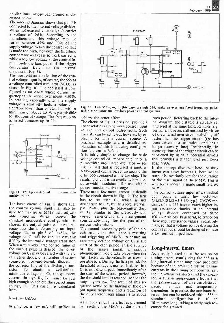
Fig. 12. Two 555's, or, in this case, a single 556, make an excellent fixed -frequency pulse -width modulator for low -loss power control systems.
achieve the zener effect.The circuit of Fig. 11 does not provide alinear relationship between control inputvoltage and output pulse -width. Suchlinearity can be achieved, however, by re-placing RI with a current source. Apractical example and a detailed ex-planation of this interesting configura-tion is given in Ref. I.It is fairly simple to change the basicvoltage -controlled monostable into apulse -width modulated oscillator - seeFig. 12. All that is required is anotherAMV-based oscillator, set up around theother 555 contained in the 556 chip. Theresulting circuit is an excellent, low -loss,pulse -width modulator for use with apower -transistor driver stage.There are a few more interesting detailsin the circuit shown in Fig. 12. The firsthas to do with CI, which is notdischarged to 0 V, but to a level set withp.d. R4 -Rs, plus the base -emitter dropof Ti. Similar to the previously dis-cussed `zener-trick', this arrangementconsiderably magnifies the span of theoutput pulse -width.The second interesting point of the cir-cuit entails the simultaneous resettingand triggering of MMV2 to ensure anaccurately defined voltage on Ci at thestart of the each period. In the absenceof the trigger signal, a curiousphenomenon would take place when theduty factor is, theoretically, as close aspossible to 1. During the first period, thethreshold voltage is not reached, so thatCI is not discharged. Immediately afterthe start of the second period, however,the threshold level is reached, so that theoutput goes low. The result of this se-quence would be the halving of the out-put signal frequency, and a reducton ofthe duty factor from almost 1 to about0.5.As already said, this effect is preventedby resetting the MMV at the start of
each period. Referring back to the inter-nal diagram, the bistable is actually setand reset at the same time. Reliable trig-gering is, however, still ensured by virtueof the internal reset circuit switching offfaster than the trigger circuit (Q15 hasbeen driven into saturation, and has alonger recovery time). Incidentally, therecovery time of the trigger circuit can beshortened by using a potential dividerthat provides a trigger level just lowerthan 1/31.1b.In the concept discussed here, the dutyfactor can never become 1, because theoutput is invariably low for the durationof the reset signal of the MMV. This iswhy R3 is generally made small relativeto R2.The control voltage input of a standard555 forms a fairly low resistance(5 kQ//10 kg =3.3 kQ typ.). CMOS ver-sions of the 555 have a much higher in-put resistance thanks to an internalvoltage divider composed of three100 kQ resistors. In general, tolerance onthese input resistance values is relativelyhigh, so that a voltage source driving thecontrol input should be designed to havea low output impedance.
Long -interval timersAs already hinted at in the section ontiming errors, configuring the 555 as along -interval timer may pose problemsbecause of the inevitable role of leakagecurrents in the timing components, i.e.,the high -value resistor(s) and the capaci-tor. A further aggravating effect is thatthe leakage current of an electrolytic ca-pacitor is age- and temperature -dependent. In practice, the maximum in-terval that can be achieved with a 555 instandard configuration is 10 to30 minutes long, taking a fairly high tol-erance for granted.
EE
February 1989
2
AMV =2- MMV
6
/east
discharge
'12556wtput
!tress:AS
.Rtroltditage
3Uzi
T
CLK
V c,c
0_ 7A_114020/4040
Rd
O
C3
'Cl
O10
rase!
1/2556
8 trigger stitp6t
trresitsii
cAntrciroitage
11
.4
T860001-22
uo00
Fig. 13. Long -interval timers are best realized
One solution to obtain better -definedand longer intervals would be thecascading of 555s, so that each is trig-gered by the previous one. This is not avery neat solution to the problem, how-ever, since all timing errors of individualtimers in the cascade simply add up (ac-cumulation effect). Moreover, the dur-ation of the interval rises only linearlywith the number of 555 stages. The in-crease can be made exponential by fol-lowing one 555 in AMV mode with adivider as shown in Fig. 13. Dependingon the application, the n-th output ofthe divider can trigger a further 555, thistime in MMV mode. In this set-up, the555 in AMV mode is conveniently di-mensioned for optimum accuracy(average values for R2 and R3, and alow -leakage capacitor for Ci), whilecascaded dividers afford timer intervalsof hours, days or even weeks.
CMOS versions: 7555 andTLC555Intersil was the first to introduce the7555, a CMOS version of the 555. Alittle later, Texas Instruments, in linewith its consistent and successful policyof producing LinCMOS (linear CMOS)versions of 'bipolar bestsellers', came upwith the TLC555. As with a number ofwell -established opamps and com-parators, the TLC555 and TLC556 fromTI were an instant success.In general, current consumption of theCMOS versions has been drastically re-duced with respect to the bipolar 555 -from 10 mA to 100 µA, while theminimum supply voltage has beenlowered to 2 V. Obviously, these featuresare of great importance for the design of
with the aid of a ripple -cascade divider.
battery -powered circuits. The CMOSversions do not suffer the large peak cur-rent at output switch -over, while the in-put bias current of the threshold com-parator, and the leakage current of thedischarge transistor, are also significant-ly reduced. These features of the newdevices are advantageous because theyallow a higher charge resistance for thecapacitor, bringing longer timing inter-vals within reach.Thanks to the virtual absence of satura-tion effects commonly associated withbipolar transistors, speed of the newCMOS 555's has also increased. In alaboratory test, a standard 555 gave up
at about 180 kHz, whereas a 7555 scored1.1 MHz, and a TLC555 even 2.4 MHz(test conditions: AMV configurationwith RI=R2= 220 52 and Ci=100 pF).As far as output current is concerned,however, the bipolar 555, with its sinkand source capabilility of 200 mA, isstill superior to the CMOS versions. The7555 supplies a maximum of 5 to50 mA, depending on the supply voltage(10 mA at 10 V). The TLC555 has asymmetrical output with a source andsink capability of 10 mA and 100 mA re-spectively. Ergo, where the replacementof a standard 555 with a CMOS type isconsidered, the current requirement ofthe load should be taken into account (astandard 555s is often used to power arelay direct).
Reference:
1. Long-range infra -redreceiver. ElektorNovember 1987; p. 40 and 41.
.I
transmitter -Electronics
Table 1
min.555typ. max. min.
7555typ. max.
TLC555min. typ. max. unit
VrrNaa 4.5 18 2 18 2 18 V
Supplycurrent
2V5V10V
-
310
-
512
-
0.080.12
-0.40.6
0.170.36
0.250.350.60
mAmAmA
OutputCurrent
hank
Isixirce
200200
81
8020
10010
mAmA
Thresholdcurrent
100 250 10 0.01 nA
Dischargestate -offcurrent
20 100 10 0.1 nA
MMV timingerror 1 3 2 1 3 %
Temp. drift 500 250 - Pim,*
14,, driftOutput
0.5 0.3 1 0.1 0.5 %N
rise -timefall -time
100100
300300
7575
2075
nsns
Ins. 0.5 1 2 MHz
data valid at Ta=25 °C.
EEFebruary 1989
29
DESIGN IDEASThe contents of this column are based solely on information supplied by the author
and do not imply practical experience by Elektor Electronics.
SPEED CONTROL FOR ASYNCHRONOUS MOTORS
The possible design is discussed of a remarkably simplefrequency converter that ensures good torque over a wide speedrange for mains -powered motors of up to 100 W. Applications of
the speed controller include ventilators and pumps.
Induction motors with a squirrel -cagerotor are popular because of theirsimplicity and low cost. Compared withother types of AC -powered motors,speed control for the squirrel -cage in-duction motor, is, however, a relativelycomplex matter. Simply reducing themotor voltage generally gives poor speedcontrol, and results in inacceptable lossof torque at low speeds. Frequency con-trol of the motor supply voltage is a bet-ter method, since it exploits the fact thatspeed of the squirrel -cage motor isdirectly related to frequency. The basicrequirements of a frequency controllercircuit may be defined after brieflydiscussing the operating principles of thesquirrel -cage motor.
A revolving transformerThe rotor in a squirrel -cage inductionmotor is of remarkable rubustness andsimplicity. The windings of the rotor areformed by conduction bars, connectedat either end by a short-circuiting ring(see Fig. la). In a practical construction,this cage -like structure is encapsulated ina tin-plate cover to keep the distributionof the magnetic field under control. Theshort-circuiting rings are, however, near-ly always visible when the motor isdismantled.The cage -type rotor is placed in a statorwith two sets of poles. Figure lb showsthis structure for a single-phase motor.One set of poles holds the main winding,the second the auxiliary winding. By ap-plying the mains voltage direct to themain winding, and, phase -shifted by90'. to the auxiliary winding, the two
by K. Walters
87. 11a
0.sin (WI + 90°)890039 - I I b
Fig. 1. Basic structure of the squirrel -cage induction motor: rotor (la) and cross-sectionalview of the stator and rotor (lb).
30 EE
February 1989
N1...N4 = IC2 = 4011 (4093)
2x1N4148
0211
D3...D6 = 1N4004
MAINS
Fig. 2. Circuit diagram of the speed controller for asynchronous motors.
sets of poles create a rotating magneticfield. As in a transformer, a voltage is in-duced in the conduction bars of thecage. The ends of the bars are, however,commoned, giving rise to a high currentthat, in turn, generates a magnetic field.This causes the cage to be drawn alongwith the rotating magnetic field providedby the stator. Because the motor starts torun in the direction of travel of the statorfield, the speed at which the rotor 'sees'the magnetic field revolve, is reduced.This effectivly reduces the current in theconduction bars, and, with it, the mag-netic field strength of the cage. In prac-tice, the actual movement of the cagelags that of the magnetic field by a fewpercent, so that motor speed is notsynchronous with the stator field or, forthat matter, the mains frequency. Hence,the type of motor discussed here issometimes referred to as an asyn-chronous type.
The auxiliary winding is, in principle,only required to overcome the inertia ofthe cage when the motor is started. Insome motors, the supply to this windingis interrupted by a centrifugal switch.Unfortunately, this type of motor cannot be used with a speed control circuitof the type discussed here, because thecentrifugal switch remains closed at rela-tively low speeds and would cause theauxiliary winding to burn out.
Theoretical background to thespeed controllerSince the theory of operation of the in-duction motor is covered in numeroustext books, it is sufficient here to con-centrate on a basic equation that hasrelevance for speed control:
U/ f = A-$:1)
quency of the motor voltage, k a con-stant, and (I) the magnetic flux of thestator field. The magnetic flux should,however, also be constant to prevent anylikelihood of the tin-plate stator encap-sulation running too hot as a result ofsaturation effects. Reduction of the flux,on the other hand, results in loss of tor-que. With this in mind, the above equa-tion can be simplified to
U/f= constant
leading to the conclusion that frequencycan be controlled as desired, along witha corresponding change in the motorvoltage.There are, of course, practical limits tosuch a simple equation. Notably at rela-tively low frequencies, when the ohmicresistance of the stator winding becomessignificant, it is no longer allowed tochange the supply voltage in proportionwith frequency. This is mainly becauseincreasing frequency means increasing
clk
J-11 j-il1._100ms
U
motorvoltage
-U
141._100ms
T
(18+2x1...100)ms
it
.11.111.
890009-13
where U is the motor voltage, f the fre- Fig. 3. Timing diagram showing the relation beween the main signals in the circuit.
EE
February 1989the copper losses.There is another factor that limits theuse of the above equation: thebreakdown voltage of the motor windingat a particular frequency. Fortunately,during normal operation of the motor,the safe limits for the applied voltage arenot easily exceeded.
Design of a speed controlcircuitThe circuit diagram of the speed con-troller is given in Fig. 2. Although thecircuit is offered as a design idea, it isnone the less excellent for use with rela-tively small, lightly loaded, motors. Theexperimental nature of the circuit hasmainly to do with the supply voltage andthe way in which the motor is driven.In the proposed circuit, the mainsvoltage is rectified by D3 through D6,which supply about 2401/2339 V. Thisvoltage powers a half -bridge circuit thatincludes the motor. One disadvantage ofthe half -bridge is that the ma)thnummotor supply voltage is limited to abouthalf the rectified voltage. This results insome loss of torque, but has the advan-tage of avoiding damage to the motorwhen the ratio U/f is incorrect. For-tunately, there are ways to improve onthe supply voltage, as will be detailedfurther on in this article.
The central part in the speed control cir-cuit is multivibrator/bistable ICI. Themultivibator in this chip is configured asan astable multivibrator, whosefrequency -determining network is con-nected to pins 1, 2 and 3. The charge anddischarge time of CI can be controlledseparately by virtue of Di and D. Thisarrangement results in a clock signalwith a fixed 'high' time of 9 ms, and avariable 'low' time of 1 to 100 ms. Theclock signal is divided by 2 in ICI, sothat the Q and Q outputs supply a sym-metrical rectangular signal of frequencybetween 4.6 and about 50 Hz. Gates NIand N2 combine the 3 output signalssupplied by ICI into 2 pulse -like signalsthat are never 'low' simultaneously toprevent Ti and T2 conducting at thesame time and causing a short-circuit.The pulses from NI and N2 ensure, via13, T4 and the primary winding of Tri,that an alternating magnetic field iscreated in the transformer. This fieldcauses an alternating voltage of about
Vpp in the secondary. Rectification bythe base -emitter junctions of Ti and T2,in combination with the anti -phase ar-rangement of the secondary windings,causes the transistors to conduct in alter-nating fashion.
The timing diagrams in Fie. 3 further il-lustrate the operation of the speed con-trol circuit. The asymmetrical clocksignal and the Q and Q pulses derivedfrom it are shown in the upper 3
diagrams. Gates NI and N2 generate ac-tive pulses A and B, which are 1 msapart under all circumstances toguarantee that the output transistors arenever on at the same time. The (ideal)motor voltage is drawn in the lowerdiagram. The peak value of it cor-responds to half the supply voltage(about 170 V). The effective value, U.,is fairly simple to calculate from
Unns= 9(9+n)
where U is the peak value, and n theperiod, which has a value between 1 and100. It is seen that the effective voltage isinversely proportional to the period, andproportional to the frequency. The cruxof the matter is, therefore, to find a com-bination of the fixed and variable part ofthe clock pulse, that resuls in a constantvalue of U/f. For a 240 V, 50 Hz, motor,this constant is 240/50=4.8. In practice,however, this value is dimensionedhigher at the lowest frequency. This isdone chiefly to compensate the increas-ing influence of the ohmic resistance ofthe stator windings. A value lower than4.8 is chosen at the highest frequencybecause it will be desired to regulatedown to 50 Hz even with a too lowsupply voltage. The reduced torque caus-ed by this compromise is not a problemin most cases.
Construction and safetyprecautionsThe prototype of the speed controllerwas built on a small piece of veroboard.Since a part of the circuit is not insulatedfrom the mains, all solder junctions arekept at least 6 mm apart, and non -usedtracks are removed by overheating themwith a high -power soldering iron. Alsowith safety in mind, the power section ofthe controller was built separate fromthe oscillator, in a moulded ABS enclos-ure.
Further considerationsThe following is aimed at constructorswishing to experiment further with thecircuit. It should be noted that the pointsraised below are mainly theoretical, andhave not been put to the test in any prac-tical circuit.Capacitors C2 and C3 form the passivearm of the bridge circuit, and have aconsiderable influence on the motorvoltage. The higher the motor power, thelarger the capacitance of C2 and C3 toensure the shape of the motor voltage.When these capacitors are too small, anoscilloscope will clearly show their beingcharged and discharged. For a 100 Wmotor, C2 and C3 should both be in-creased to about 25 µF.
a
Fig. 4. Two alternative rectifier circuits toobtain a higher motor voltage.
Obviously, there is a clear point in rais-ing the supply voltage of the bridge cir-cuit. In principle, this voltage should beso high that the motor is fed with 240 Vat 50 Hz. This supply level, U, is ob-tained from
U=2 x 240x9+1 - 533 V9
This requires powering the circuit from1/2V2 x533.----377 V, which is an uncom-mon voltage. A voltage of 2 x 339 V is,however, could be made available by rec-tifying the mains voltage as shown inFig. 4a. Unfortunately, this voltage istoo high if the duty factor is not alteredto maintain a correct ratio U/f.An alternative rectifier, the full -wavetype shown in Fig. 4b, ensures that thehighest voltage remains below 339 V, butat the same time causes the peak value ofthe motor voltage to increase from 170 to339 V.
In conclusion, designers should take dueaccount of the duty factor and frequencyof the control signal, as well as thesupply voltage of the bridge circuit,since all these are tightly linked factors.
14
111 EE
February 1989
IN I ERMEDIATE PROJEC
A series of projects for the not -so -experienced constructor. Although each article willdescribe in detail the operation, use, construction and, where relevant, the underlying
theory of the project, constructors will, none the less, require an elementaryunderstanding and knowledge of electronic engineering. Each project in the series
will be based on inexpensive and commonly available components.
2. Dark -room timer
This month's intermediate project is a low-cost timer that shouldappeal to the many photography enthusiasts convinced that thesimple equipment in their dark -room can beat the print qualityoffered by high -street photo development centres. Providing anaccuracy of one-third f-stop, the timer should be of particular
interest for those who like to influence the contrast of the print byexperimenting with different exposure times.
Optimum print quality of a photographcan only be achieved when thephotographic sensitive paper is correctlyexposed to light. In practice, this meansthat the photographer has to be able toaccurately control the exposure time.With all the other, simultaneous, ac-tivities in the dark -room, such as hand-ling the prints in the fixing and develop-ment baths, it is not so easy to devote allone's attention to timing the exposure.Many photographers would, therefore,like to use an electronic timer. These areavailable commercially, but the cost ofeven the simplest type may well be higherthan the home-made type describedhere. This is so because the present timeris built from commonly available, inex-pensive parts which may, for the greaterpart, be held in the junk box already.
The block diagram of the dark -roomtimer is given in Fig. 1. Rotary switch Siselects between three basic exposuretimes, which can be multiplied, orlengthened, by a factor 2, 4, 8, 16 or 32,as selected with another rotary switch,S2. As shown in the above photograph,this results in 18 different exposure inter-vals in 1/3 -f-stop increments, which isaccurate enough for most applications.A continuously variable timer adjust-ment is purposely not used because thisis cumbersome to calibrate and match toa scale that is accurate and at the sametime easy to read. The function of the`start' and 'stop' of the timer switches
by A. Rigby
should be evident. Switch 'stop' may bepressed at any time to switch off thelamp - a very useful feature when it isfound that an incorrect exposure timehas ben set. A further switch, marked`lamp on', is provided for adjusting thelight source before the photosensitivepaper is used.For reasons of safety, the lamp in theenlarger is powered via a transistor -
driven relay. To enable adjustment of thelamp, the driver transistor can bebypassed with the aid of switch Ss, sothat the relay can be actuated manuallyalso.Bistable FF is the most essential part inthe circuit. When it is set by pressing the`start' switch, output Q goes high, sothat the lamp lights until either 'stop' ispressed, or a reset pulse is generated by
Fig. 1. Block diagram of the dark -room timer.
the clock oscillator. Since the set inputof the bistable is connected to the resetinput of the clock oscillator, this will bereset to state nought, and start countingdown the lamp -on time, when 'start' ispressed. The lamp -on time is, obviously,determined by the positions of the rotaryswitches, which select the basic timing(Si) and the multiplier (S2) to give atotal exposure time. Output Q (invertedQ) of the bistable is fed back, via an in-verter, to the stop input of the coun-ter/oscillator to prevent this counting onas the bistable has been reset. This ar-rangement is purely a matter of ensuringcorrect operation of the circuit at alltimes, since a single reset pulse is, inprinciple, enough for the bistable.
The circuit in detailThe circuit diagram of Fig. 2 shows thatonly the clock oscillator and the powersupply are integrated circuits; the re-mainder of the functions are realizedwith the aid of discrete components.The Type 4060, 1C2, contains an oscil-lator and 14 series -connected bistables(so-called ripple cascade). Internally, theoscillator signal is applied to the firstbistable, which drives the second, and soon. Since each bistable divides its inputsignal by two, a total of 15 signals is, inprinciple, available, each of half the fre-quency of the previous one. On the 4060,10 of these 15 signals are available onpins; 6 of them are used in the presentapplication.
The parts connected to pins 9, 10 and 11of the 4060, with the exception of Ri,determine the frequency of oscillation.Switch S makes it possible to changethe capacitance connected to pin 9, orthe resistance to pin 10. The frequencyof oscillation, To, is given by
fo=-1/(2.2RC).
R in the equation is formed by the sumof resistances Pi and R2. Factor C isformed by C2, which has a value of470 nF. If Si is set to the left position,the value of R is lowered since Pi andP2 are then connected in parallel. Thismeans that the oscillator frequency in-creases. With Si set to the right pos-ition, CI and C2 are connected in paral-lel, so that the oscillator frequency islowered.Since the IC forms a clock circuit, it maybe more convenient to think in terms ofperiods rather than frequencies. Theperiodic time increases when Si is
EEFebruary 1989
turned clock -wise (that is, in the circuitdiagram).With Si set to the centre position, fo willbe about 8 Hz, which corresponds to aperiod of 0.125 s. This is not theminimum time increment, however,because dividers follow the oscillator.Pin 5 of the IC is output Q5, which sup-plies a signal with a period of 4 s (8 Hzdivided by 25 equals 0.25 Hz), i.e., itshigh and low half -periods are 2 s long. Itis this signal that determines theminimum time interval. When the 4060is reset by pressing the 'start' button, allcounter outputs are made low, and ittakes 2 s before pin 5 goes high to resetthe bistable.
Before the reset pulse generated by the4060 can have any effect, the bistablemust be set. This happens when the`start' button, S4, is actuated. A voltageis applied to the base of T2, via R6 andD2. This voltage exceeds the base -emitter threshold, and causes thecollector -emitter junction to conduct.This means that the collector voltagedrops to about 0.1 V, which, in turn,results in Ti and T3 being turned off.The collector voltage of T3 rises toabout 5 V, so that T5 is driven, and T2 iskept conductive. T4 ensures that relaydriver T5 can not conduct as yet. This isbecause T4 receives base current viaso that it short-circuits the base -emitterjunction of Ts. This situation onlyceases when the 'start' key is released.
With Si set to the centre position, factor Fig. 2. Circuit diagram of the dark -room timer.
February 1959
reset 4C60
cbck 4060
05 4060
06 4060
Q7 4060
reset input FF
Q output FF
lamp
start start stop
Z
hl]h by CO hgf-i by stop
886100.13
Fig. 3. Timing diagram. The dashed part of the clock signal indicates that the oscillatorwould be able to operate since Ti does not conduct. This condition is, however, prevented bythe level at the reset input.
Transistor T4 is included in the circuit toensure that the lamp lights as soon as thecounter starts. Without the transistor, atiming error would arise, since the lampwould light when S4 is pressed, and thecounter would start when S4 is released.When the selected time interval ends, orwhen 'stop' is pressed, the base of T3 istaken high, so that the collector voltagedrops. As a consequence, T2 and Ts areturned off, and the bistable is kept resetvia Rs.
Timing diagramThe operation of the circuit is further ex-plained in the timing diagram of Fig. 3.In this, it is assumed that Sz is set tomultiplication factor 8 (Q8). For thesake of clarity in the timing diagram, thefrequency of the oscillator signal isshown lower than actual.The first part of the diagram shows anormal timing event. A brief descriptionof this is given below:
1. 'Start' key is pressed, but oscillator isnot yet enabled by Ti since reset lineis still low; bistable output is high.
2. 'Start' key is released; oscillatorstarts; lamp lights, ripple dividershalve the oscillator frequency.
key is actuated after the circuit has beenstarted. As expected, this reacts in thesame way as it would have when a resetpulse is generated by the 4060.
Some more detailsDiodes are fitted in three positions to ob-
viate cross -effects between parts of thecircuit. Di prevents the outputs of the4060 being overloaded when they are lowwhile the 'stop' key is being pressed. D2prevents the 4060 remaining reset whenthe collector voltage of T3 is logic high.Finally, D4 protects switching transistorTs against reverse EMF generated whenthe relay is de -actuated.All resistors, with the exception of pull -down RI2, function as current limiters,while the decoupling capacitors in thecircuit serve to eliminate interference.Voltage regulator IC2 allows the dark-room timer to be powered from an inex-pensive mains adaptor with a DC outputbetween 9 and 15 V.
All on one boardThe printed -circuit board for the timer isshown in Fig. 4. Apart from the elec-trical components, the PCB also ac-comodates a number of mechanicalparts, such as the relay, rotary switchSz, and the two push -buttons, so thatvery little wiring is required. The directsupply voltage and the lamp voltage in-put and outputs are made in two-wayterminal blocks for PCB mounting.Since most enlarger lamps work fromthe mains, great care should be taken inthe connection of live wires to IC2
(mains input) and IC3 (lamp). The twoDigitast switches (`start', S4, and 'stop',S3) must be mounted on short pieces ofrelatively thick wire to enable them toprotrude from the front panel, on towhich S2 is secured. Alternatively, S3and S4 may be replaced by less expesivepush -buttons for panel mounting.Voltage regulator IC2 can do without aheat -sink, and is bent back on to thePCB as shown on the overlay.
The second part of the diagram il-lustrates what happens when the 'stop' Fig. 5. Completed board before fitting into the enclosure.
EEFebruary 1989
Fig. 4. Track layout and component mounting plan of the printed -circuit board.
Setting upThe completed circuit should be set upcarefully to ensure optimum results.First, set Si to the centre position, andS2 in position xr. This setting cor-responds to a timer interval of 2 s on thefront panel. Then adjust Pi until therelay is actuated for 2 s after pressing the`start' key. This is a coarse adjustment,followed by advancing the rotary switchby 4 steps, and carefully re -adjusting Pifor an interval of 32 s. The same is donefor the 24 s interval to enable adjustingP2. Finally, check whether the thirdposition of S2 yields the correct inter-vals. No adjustments should be neededat this stage, since this range derives itsaccuracy from the setting of Pi. If unac-ceptable deviations are observed, ex-change CI by another type.
FinishingThe completed and aligned board(Fig. 5) is built into an ABS sloping- Fig. 6.
Parts list
Resistors (± 5%1:R1 =IMORz =68K113;R4;Re:Rio=4K7Fi5;l17=47KFle:Ra;Rt s = 10K
Enclosure: e.g. Hammond Type 1595C.PCB Type 886100 (not available ready-madethrough the Readers Services).
front cabinet as shown in the introduc-tory photograph. As a finishing touch,provide the front panel with letteringand signs as suggested in Fig. 6.Strain reliefs and good -quality grom-mets should be used where the mainscables enter the enclosure. In some cases,it may be preferred, however, to use aready-made socket for the incomingmains voltage. It is imperative to ensurecontinuity of the earth line to theenlarger lamp when such a socket isused. 14
DARK - ROOM TIMER
F--1.5 -6-12-24 -482-4-8-16-32-64
I I
25 5-to-20-40-80
START
LAMP ON
STOP
886100.10
Design of a possible front -panel for the dark -room timer.
36 EE
February 1989
COMPUTERS: AN OVERVIEW
Early machinesIt seems a far cry from the first auto-matic computer, the Automatic Se-quence Controlled Calculator-ASCC.Yet, it is not quite half a century ago thatthis machine, the result of a collabor-ation between Dr Aiken of Harvard Uni-versity and IBM, was presented to Har-vard University in 1944.Dr Aiken based much of his design onthe Analytical Engine conceived in 1832by Charles Babbage. Like Babbage'sbrainchild, the ASCC used sets ofwheels as registers to store numbers. Themachine was composed of no fewer thannearly 800,000 parts and almost 900 kmof wire.
The first electronic computerThe first digital electronic computercame close on the heels of the ASCC: itwas in full operation in 1946. NamedENIAC, acronym for ElectronicNumerical Integrator and Calculator, itwas designed by Dr J. Eckert and Dr J.Mauchly of the University of Penn-sylvania.Where the ASCC was a mechanicalmonster, the ENIAC was an electricalone: it contained some 18,000 electronicvalves and consumed around 150 kW ofelectric power.Not long after the ENIAC had beentaken into operation at the University ofPennsylvania, a course of lectures wasdelivered at the same university thatformed the mould for today's electroniccomputer. The lectures, The Theory andTechniques of Electronic Digital Com-puters, contained the principles for thedesign of electronic computers that hadbeen worked out by a group ofmathematicians and electrical engineersheaded by a, now famous, Hungarianprofessor of mathematics working atPrinceton, Johann on Neumann.From then on, computer technology ad-vanced at an accelerating pace. So muchso that as early as 1956 Sir GeorgeThomson, the eminent physicist,declared that
`the electronic computer has not madethe headlines in the same way asnuclear energy, but I believe it is com-parable in importance. The ability toapply precise reasoning to very largeamounts of data in a reasonable time
by K.A. Roberts, BA
is something new, and the introduc-tion of computers into science mayprove not much less important thanthe introduction of mathematics in theseventeenth century'.
The mainframe eraDuring the 1950s and 1960s, the elec-tronic computer evolved into a useful,but expensive tool. Scientific research,defence organizations, large accountsdepartments, and educational establish-ments had all begun to use some kind ofcomputer.The advent of time-sharing systems sawan even greater degree of computerpenetration. The obvious advantages ofallowing many users within a singlecompany or organization to make simul-taneous use of a central computer werequickly spotted by commercial en-trepreneurs who set up commercial time-sharing services. Time sharing was formany the only way of making use ofcomputer power: computers were stillvery expensive. Their cost lay not only inthe initial outlay, but also in terms of op-erational staff, space and power re-quirements.
The minicomputerBecause of the high cost of computers,manufacturers realized the need for asmaller, relatively less complex (and thusless expensive) machines. The firstmanufacturer to bring one of thesemachines on the market was Digital (in1963). In comparison with the main-frames then current, it was a limitedmachine: it ran only one program at atime, processed data in 12 bit -words andhad only 4 k of memory. None the less,its advantages were obvious: it was notmuch larger than a domestic freezer, didnot require an army of trained supportstaff, and its cost was only about5-10% of the mainframe computers ofthe day when it was announced. Since itsold extremely well, penetrating not onlynew, but also existing, markets, its pricerapidly came down, so that even morecustomers were attracted. By the early1970s, no fewer than 70 US firms weremanufacturing the so-called minicom-puter.
Personal computersWhereas the minicomputer came aboutfor sound economic reasons, themicrocomputer, perhaps better knownas the personal computer, was, like radioin its early days, developed by amateurs.It should be noted that the industry atthat time did not think a personal com-puter would ever cotton on (and this isonly 15 years ago!). It was in 1974 thatthe July edition of Radio Electronics, anAmerican hobbyist magazine, carried anarticle for the home construction of asmall computer. The Mark 8, as it wascalled, used an Intel 8008 microproces-sor, had 256 bytes of RAM (expandableup to 16 k) and had no ROM.Despite its limitations, interest in theMark 8 was phenomenal and salesof parts for it far exceeded expections.This interest, coupled with the introduc-tion of Intel's 8080 microprocessor,prompted MITS, a small US electronicscompany, to introduce the Altair 8800.This design was also aimed at the hob-byist and designed for another Americanamateur publication, Popular Elec-tronics. The project was published as aseries of constructional articles, the firstof which appeared in the January 1975edition.The computer was offered to readers ofPopular Electronics for $650 fullyassembled or 5395 in kit form.
Apple Computers is bornInterest in the Altair 8800 caused the set-ting up, all over the USA, of `computerclubs', run by, and for, amateur en-thusiasts. A member of one such club inCalifornia, Stephen Wozniak, a self-taught computer engineer, got the ideaof designing and manufacturing asimilar kind of small computer, based onthe newly -introduced 6502 microproces-sor.Wozniak designed a small computer,which was received enthusiastically byhis fellow club members. However, whenhe approached his employers, HewlettPackard, to try to interest them inmanufacturing his computer, he metwith a bland refusal. Hewlett-Packarddid not think there was a sufficientlylarge market for the machine!A friend of Wozniak's, Stephen Jobs,thought differently. He approached anumber of potential buyers and eventu-
ally got a contract for a quantity of theWozniak boards. Jobs and Wozniakthereupon went into business forthemselves and formed what is now oneof the largest computer companies in theworld: Apple Computers. They havenever looked back!All this happened only 15 years ago.Today, the personal computer market faroutstrips the mainframe and minicom-puter markets, and tens of millions ofPCs are in use the world over for amultitude of applications.
Parallel processingIt was stated earlier on that vonNeumann's model formed the mould fortoday's computer. That was true untilthe arrival of the transputer. The pro-cessor in traditional computers canhandle only a single instruction at atime. This is true even in multi-user andmulti -tasking systems such as UNIX andconcurrent MS-DOS, where the pro-cessor appears to be engaged in severaltasks at a time, but in reality assigns timeslots to portions of the relevant tasks.Obviously, the faster the processor, theless users are aware of the time-sharingprocess.The transputer is a radical departurefrom the von Neumann concept. It isnormalized for true concurrency. Paral-lel processing of data and instructions is
very fastpoint-to-point communication channelsbetween processes as well as individualtransputer modules. There is, in prin-ciple, no limit on the number oftransputer modules that can be connec-ted to form a computer.In contrast to other processors,transputers enable defining the speed ofthe system simply by adding as manymodules as required. The IMS T800transputer from Inmos, the designersand manufacturers of the transputer, inits 20 MHz version outperforms all of its32 -bit competitors, including theNational Semiconductor NS32332-32081and Motorola's MC68020-68881.The calculation performance of the IMST800 is equal to that of the VAX 8600scientific computer from DEC, while anetwork of ten IMS T800 modules offersthe speed and processing power of theCyber 205 supercomputer from ControlData Corporation.Because of their ability to work co-operatively in parallel on a number ofdifferent but related tasks, transputersare well suited for use in so-called paral-lel processing. By designing computersthat work on a number of tasks simul-taneously, instead of doing everything insequence, designers aim to mimic moreclosely the workings of the human brain.Transputers are also being assigned toless futuristic applications, includingdesk top supercomputers, laser printersand what have been nicknamed turbo-
chargers where the transputer is used asan add-on unit to an existing system toupgrade its performance. High-performance graphics, engineeringworkstations, and robotics are otherareas where the transputer has alreadybegun to make an impact.
The optical computerBeyond the transputer, research is goinginto photonic and molecular -based com-puters. Basically, the heart of a com-puter is the transistor (although theremay be thousands of them on one IC).A transistor is nothing but a switch thatcan flip backwards and forwards be-tween two states. Therefore, computersare chains of switches. They treat se-quences of ons and offs to denotenumbers (in which case ons and offs areread as the ones and zeros of binarycounting) or to denote true or false (inwhich case chains of switches may beused as the building blocks of algebraiclogic). Researchers at AT&T's Bell Lab-oratories and at Edinburgh's Heriot-Watt University have invented a devicethat does for light what the transistordoes for electrons. This switch, knownas a Bistable Optical Device-BOD-ortransphasor, is essentially an opticaltransistor. Light emerges from it as astrong beam (on) or a weak one (off).Put a bunch of transphasors together,shine laser beams through them, andyou have the basic ingredients of an op-tical computers.
The chemical computerEven more advanced is the chemicalcomputer that will operate in the sameway as the human brain. The Scienceand Research Council-SERC-a fewyears ago set up a multi -million poundresearch project, called MERI-Molecular Electronics ResearchInitiative-that is intended to keepBritain in the forefront of advancedcomputer technology.The idea of a molecular computer wasfirst suggested by an American scientist,Forest Carter, as a means of overcomingheat dissipation problems in electroniccomputers. Living organisms are madeup of carbon -based compounds, betterknown as organic compounds that inter -react to make possible, among manyother things, such functions as thinking.Under the MERI, biologists and elec-tronics experts will work side by side toengineer carbon -based chemicals thatcan replace electronic components nowmade from silicon. These chemicals willbe able to interact at molecular level andwill, therefore, provide enormous com-puting power in a very small space. Sincemolecules are interconnected in three di-mensions, the computer based oh themwould be able to use parallel processing(like the transputer), making it very fast.
EE 111February 1989
It would also be better at patternrecognition than conventional com-puters.
Some newcomersBack to today, one of the most excitingPCs to have come on the market in thepast 18 months is undoubtedly the Ar-chimedes. It is the first PC equippedwith a 32 -bit wide bus at a veryreasonable price. Its processor is anAcorn Risc Machine-ARM-that ischeap and very fast. The high processingspeed of 4 MIPS (million instructionsper second) is the result of RISC (Re-duced Instruction Set Computer) tech-nology. The philosophy behind this tech-nology is that it is better for the pro-cessor to work very fast from simple in-structions than slowly from complex andoften little -used instructions. Already,some versions of ARM have operated,under laboratory conditions, at process-ing speeds approaching 20 MIPS. It isnoteworthy that although the ARM iscomparable to Intel's 80836 chip in per-formance, its price is only about 1/100thof that of the 80836!Another interesting introduction justover a year ago was from the man theycan't keep down: Sir Clive Sinclair. HisZ88 portable computer is cheap, small(smaller than a size A4 sheet of paper)and weighs just about 2 lb (less than
All software is in ROM and it isnot compatible with anything. The Z88is intended as an end -product andcomes, therefore, with all necessary soft-ware. Its ROM, apart from a number oftools, also contains a spreadsheet, adiary, a word processor and the well-known BBC BASIC. The programs maybe used simultaneously. There is, ofcourse, a serial connection for a printerso that texts from the word processormay be sent straight to the printer.
FinallyWith all the kerfuffle about computersspeeds, peripherals of a thousand kinds,software of unimaginable variety, it issometimes well to reflect on the fact thata computer can really do only twothings: carry out sequences of relativelyunimportant operations like adding orcopying, and choose between alternativesequences.
Entry-level STEbus systemA low-cost development system for theSTE backplane bus from Dage consistsof a powered Fastframe enclosure withopen sides for easy development access,and a single -board computer designedaround the 8052 processor.Apart from the 8052, this single-Eurocard microcomputer has four mem-ory sockets, serial I/O, and an EPROM
38 EEFebruary 1989
programmer. The 8052's mask -programmed ROM contains an 8 KBASIC interpreter. This combination offacilities provides the basis for a low-costSi hbus development system, allowingthe user to start program developmentsimply by connecting a terminal with astandard RS232 interface. When this isdone, the finished program can be blowninto PROM in -situ for use in the finaltarget system.This 8052 STEbus system provides an ef-ficient means of evaluating STEbus forindustrial control applications. Priced atunder £600, the system can be easily ex-panded over the STEbus and via VME.Dage (GB) Ltd Rabans LaneAYLESBURY HP19 3RG
Low-cost quality IBM PCcardsClaimed to be 'probably the UK's lowestprices IBM-PC interface cards' are
available from Flight Electronics. Therange is extensive and falls into threemain groups: general purpose, data com-munications, and industrial control. Itincludes a development board with built-in data and address buses and I/O linebuffer; 8-, 12-, and 14 -bit D -A and A -Dconverters; extensions; parallel/serialI/O; RAM expansion; monochromegraphic -printer; RS232 -422; SDLCadaptor; 3270 BSC emulator; IEEE -488(GPIB); and modem cards.Flight Electronics Ltd Flight House Ascupart Street SOUTHAMPTON SOl1W.
Portable PC from ITSThe ITS Portable PC has been designedto overcome what Integrated TechnologySystems believe are the most commonfailings of existing portables.The portable PC is IBM -AT compatiblewith a 12 MHz 80286 CPU, switchableto 6 MHz from the keyboard. Provisionfor an 80287 maths co -processor in-
dicates that the portable PC is suitablefor engineers, designers, and others whoneed a high-performance portable theycan use on site. 1 Mb RAM is standardon the main board and this can beupgraded to 4 Mb without using an ex-pansion slot.As well as from the mains, the PC can bepowered from an internal battery that isautomatically recharged when the PC isconnected to the mains supply.The high resolution backlit LCD displayis easily readable in any lighting con-ditions and can handle software con-figured for standard displays, includingEGA, where colours are represented byshades of grey.Prices start at £2,250, excl. VAT, for the20 Mb model.Integrated Technology Systems 5Holyrood Avenue Glenrothes FIFEKY6 3PF.
The end of ground screenloops?The VME-2000, a new design based onthe industry -standard backplaneVMEbus, has excellent cross -talkcharacteristics by virtue of aninterference -free EMI -CAD (Elec-
troMagnetic Interference Computer -Aided Design) layout, negating the needof a ground screen loop. Cross -talk be-tween adjacent signal lines, at 3.5 Vsteps with a 5ns switching time, is±160 mV. That of traditional designs istypically around ±320 mV.The system is based on the principle thata minimum number of layers reducestransmission signal problems, and fewerlayers mean thicker dielectrics with bet-ter impedance characteristics. All lineschange from one outer layer to the otherat each connector position: conse-quently, they have the same length, andthis ensures equal transmission times forall signals.System Kontaks UK The Paddock Hambridge Road NEWBURY RG14 5TQ.
Opto-22 interface for STEbusThe SPB22 interface board from Arcomprovides connection between the stan-dardized digital I/O of STEbus com-puter systems and the range of Opto-22digital signal conditioning racks, widelyused in industrial data acquisition andcontrol systems. It enables the ungradingof engineers' computing requirements toworld standard STEbus technology,while retaining existing plant wiring andthe signal conditioning scheme of Opto-22 racks.Digital I/O is taken direct from theSTEbus computer board with a 50 -wayribbon cable connection to the SPB22interface, and this converts the standard-ized STEbus format to the Opti-eescheme. The interface provides connec-
February 1989
tors for up to two Opto-22 racks andthese enable the STEbus computer to ac-cess up to 32 channels of I/O, again vialow-cost ribbon cable.Arcom Control Systems Ltd Unit 8 Clifton Road CAMBRIDGE CBI 4WH.
User programmable terminalThe CAMDATA/188 is an industrial ter-minal that is user programmable from astandard PC. It may be thought of as acustomized industrial PC at a fraction ofthe cost. It uses a 80188 microprocessorwith memory to run a PC -DOS compat-
ible operating system. Languages such asBASIC, Turbo Pascal, and C may beused.CAMDATA Systems Ltd The Old School Church Street SOMERSHAM PE17
3EG.
MAGNETIC DISKS AND TAPES
British Standard BS4783, in four parts, details how magnetic disks andtapes, whether used on a PC or on a mainframe, should be looked
after.
Most people come into closecontact with computers eitherin the home or at work. Someform of storage medium is re-quired on which to distributeprograms, to interchange databetween computers, and to holddata off-line and when thecomputer is switched off. Themost common type of storagemedium in use today is someform of magnetic media. Eventhe smallest home micro useseither a magnetic tape cassetteor a flexible disk cartridge. Thelarger computer installationsoften use either disk packs, diskcartridges or magnetic tape onopen spools, as well as flexibledisk cartridges and magnetictape cartridges.
BS 4783 has been preparedunder the direction of the In-formation Systems TechnologyStandards Committee. It hasbeen developed from adviceand information provided byGovernment computing depart-
ments, magnetic media sup-pliers, manufacturers and users.Magnetic media are manufac-tured from carefully developedhigh grade materials. Modernproduction techniques, fol-lowed by rigorous testing andinspection, ensure that theproducts supplied to the userconform to exacting standardsand are capable of a long life.To continue to benefit from thecare taken during manufacture,and to ensure optimum per-formance from a product dur-ing its life, the user should exer-cise care; this British Standardgives appropriate advice.
The larger computer instal-lations have air-conditioning,full-time operators, a medialibrary, on -site engineers and aworkshop with test and mediacleaning equipment. Carefulrecords are kept of media, withdates received, usage and er-rors. Secondary copies of im-portant data are maintained,
possibly at a different site.
At the other end of the scale isthe computer used at home orin the office. Here there is noair-conditioning, media may bestored in drawers in the samearea as the computer, operatorshave other responsibilities, nofacilities are available for clean-ing media and there is no estab-lished procedure for maintain-ing copies.
These documents give rec-ommended practices thatshould be adopted in full atlarger installations, wherefacilities are available andwhere the disruption caused bybreakdown due to media failurewould be serious. At smaller in-stallations users are advised toadopt as many of the recom-mendations as possible, balanc-ing the cost of implementationagainst the cost of mediafailure.
The publications issued bymanufacturers of magneticmedia, and of equipment forhandling it, also give advice;they should be read in conjunc-tion with this standard.
Though each of the four typesof magnetic media discussed inthe standard has specific re-quirements, many recommen-dations are common to all fourParts of the standard.
Media should be stored in alibrary, administered by alibrarian with responsibility forpreparing and maintaining ahistory record for each item.The library, operating area andequipment must be keptscrupulously clean. Advice isgiven on discipline to achievethis. In spite of all precautionsmedia will require cleaningeither on a routine basis orwhen errors occur. Routines,and suitable equipment andmaterials are discussed.
40 EEFebruary 1989
The physical properties ofmedia will only be permanentlyaffected by extreme tempera-tures and humidities, butreliable and consistent oper-ation require that the media beused, stored and transportedwithin specified ranges.
Media require visible labels;these would appear to be simpleto acquire, mark and apply.However, the adhesive must notcreep, and writing on a labelwhich has already been appliedmay damage the media.
BS4783 is being issued in fourParts as follows:
Part 1 Disk packs, storagemodules and disk cartridges.These products are based onrigid aluminium platters coatedwith a magnetic surface. In op-eration they rotate at highspeed; the write/read heads flyabove the magnetic surface,floating on the cushion of airinduced by the high surfacespeed. As the separation can beas low as 0.4 x 10 m it is essen-tial that high levels ofcleanliness are maintained andthat the disk is not distorted.Dust, debris, or even grease onthe surface can cause errors dueto instability of the flying at-titude of the head, and can, inextreme cases, result in the head
landing on the surface andscoring it. The recommen-dations on storage, handling,transportation, inspection,cleaning and maintenance aredirected at cleanliness and theavoidance, or detection of,damage to the disk. Advice isalso given on the identificationof faults.
Part 2 Magnetic tape onopen spools.This Part includes recommen-dations for storage, handling,transportation, inspection,cleaning, maintenance, faultidentification and faultrecovery. The photographswhich are included giveexamples of tape conditionsthat may lead to poor perform-ance.
Magnetic tape runs in contactwith the write and read heads;on some tape transports tapeguidance is over air bearings,on others the guides are in con-tact with the tape; the pro-duction of some debris in thetransport is inevitable. Atten-tion must be given to thecleanliness of the transport aswell as of the tape as a trans-port with dust or debris onheads or guides can causedamage to a series of tape.
As magnetic tape on openspools is the preferred medium
for archives, procedures forsuch long term storage are de-scribed.
Part 3 flexible diskcartridgesFlexible disk cartridges aretypically used, and in largenumbers, in desk top com-puters, terminals and testequipment. There is a dangerthat the very prevalence of thesecartridges, and their apparentsimplicity, will obscure the factthat their reliable operationnevertheless depends on carefultreatment. This Part includesrecommendations for storage,handling, transportation, in-spection, maintenance andfault identification. Illus-trations are included of dam-aged cartridges.
A flexible disk is encased in aprotective jacket that has win-dows to enable the write/readheads of the drive to access thesurfaces. The write/read headsare in contact with the surfacesbut in this product a liner insidethe jacket absorbs the wearproducts as the disk rotates.The greater danger to reliableoperation is physical damage'suffered if the cartridge is al-lowed to lie on a desk or table,where it may become dented or
deformed, or the disk may becontaminated by finger marksthrough the head window
Part 4 Magnetic tapecartridges and cassettes.Here the tape is protected fromphysical damage whilst hand-ling by being totally enclosedexcept for the aperture requiredto enable the head to access therecording surface. The taperuns in contact with thewrite/read head but surfacewear is reduced by the use offew tape guides. Care must betaken to prevent the casebecoming chipped whenloading or handling as thedebris may appear in the tapepath. This Part includes recom-mendations for storage, hand-ling, transportation, inspec-tion, maintenance, and faultidentification and recovery.
BS 4783 is available either in in-dividual Parts, or in a packageof all four Pans from BSISales, Linford Wood, MiltonKeynes MK14 6LE. Price: Parts1, 2 and 3 £28.50 each (£14.25each to BSI subscribingmembers), Part 4 £17.00 (£8.50to BSI subscribing members).
MOLECULAR ELECTRONICSTowards an advanced form of computer technology
by John [Jelin
Smell sensors, paper -thin tele-vision screens, movingholograms and bio-computersusing living organisms are allthe stuff of fantasy. But so wasthe silicon chip or the seem-ingly incredible notion that amillion pieces of informationcould be stored in a grain ofdust, only a few decades ago.Today's microprocessors arehardly obsolete but they arealready revealing limitations interms of size and other physicalconstraints. Where then canscientists turn to complementexisting technologies while pro-viding an exciting springboardinto the fantasies and realities
of the future?Molecular electronics, designedto harness the molecule itself asan information processor, showconsiderable promise. Gatheredtogether from disparateresearch over a range ofdisciplines, this line of thoughthas attracted considerable in-terest in Britain and has nowbeen selected as one of themajor areas of the Departmentof Trade and Industry's newLink(1) programme of col-laborative research betweenuniversities and industry.At least £20 million is to beallocated to molecular elec-tronics, half from government
sources and half from industry,to cover the so-called pre -competitive stage of develop-ment, delving into fundamentalprinciples and the feasibility ofdevices. The programme aimsto provide the platform fromwhich industry and industriallysponsored research can later de-velop exploitable products.
Practical applicationMolecular electronics usesorganic molecules to process in-formation. It goes beyond thedigital processing of conven-tional electrbnics and adds newdimensions-for example struc-
tures and shapes-to itsvocabulary. Conventional elec-tronics are analagous with thenerves in the body that triggerwhen a certain electricalthreshold is reached. Molecularelectronics resemble the whitecorpuscles that react to theshape, density or temperatureof a bacterial invader. They areconceptual in action ratherthan computational.One familiar example ofmolecular electronics in actionis the liquid crystal display seenin watches and calculators thatrespond vigorously to electricalor heat signals. These arealready in use in a number of
EEFebruary 1989
41
applications such as the head -up displays where an array ofindicators is visible in the wind-screen to aircraft pilots orrailway locomotive drivers. Theoperator is not distracted byhaving to search for gauges butcan absorb vital informationsuch as engine speed or tem-perature without moving hishead.Unfortunately today's liquidcrystals are sluggish in actionand not very sensitive. The raceis on to improve them and thenewer ferro-electric crystalsalready being tested are moreflexible and responsive. Dis-plays are now envisaged thatwill reproduce four-coloursignals on a flat screen - anobvious precursor to wallpapertelevision.
Cheap mass memoriesUsing the ultra -thin films ofone molecule thickness now be-ing produced, coupled withphoto -electronics, one couldenvisage quickly changingholograms, no more than ashort step conceptually fromgenuinely three dimensionalmoving pictures.Britain's Link programmedefines molecular electronics as"systematic exploitation ofmolecular, including macro -molecular, materials in elec-tronics and related areas such asphoto -electronics". Liquidcrystalline substances apart, itproposes to investigate organicmetals and semiconductors,non-linear optical materials,and photochromic, electro-chromic, piezo-electric andpyro-electric substances. Appli-cations to be studied include in-formation storage and trans-mission, signal processing andthin film technology.Experts see the envisagedmolecular electronic systems ascompact, flexible, cheap and ef-ficient. According to ProfessorJohn Barker of Glasgow Uni-versity, a leading worker in thefield, the smallness ofmolecules make possible verydense circuits leading to cheapmass memories.Molecules are much more noisestable and thermally stable thanconventional semiconductors.Metallic, semiconducting, in-sulating molecular componentsto be built into switches and cir-cuits would be the very leastone might expect.
Artificial intelligenceCompared with the paucity ofgood solid-state electronicmaterials, molecular materialshave a rich variety of possi-bilities ranging from simplesmall molecules, polymers andmolecular crystals to complexmacromolecules bordering onbiologically significant struc-tures not far removed fromnatural organisms. Many of thetechniques employed in syn-thetic organic chemistry couldprovide the means of buildinguseful additional propertiesinto such materials.
sight, particularly visualrecognition, that have beenmost difficult to reproduce intheir true complexity. Such ad-vances as these will offer im-portant insights into the waythe brain works and the devel-opment of artificial intelli-gence.Many scientists see the wayahead as grafting molecularelectronics on to the conven-tional variety, possibly usingthin films as an interface andproducing, in effect, conven-tional microprocessors with amuch wider range of sen-
AWill an "electronic nose" ever replace thewine expert's experience and discrimination?
A significant example of thelast technique is illustrated inthe electronic nose project be-ing conducted jointly atGlasgow University and War-wick University. By varying thestructures of a range ofpolymers it has been possible todevise a machine that cansmell. It converts the responsesof a range of sensors intosignals related to specificsmells.In modern sciene it has ap-parently been the most simplesenses such as taste, smell and
sitivities.
Insect colonyFor example, today's industrialrobots are firmly based on thedigital principle, essentially bymeasurement and counting.The concept of a robot thatcould compare, sense and feelbrings in an almost occult di-mension.The logical conclusion to thisdevelopment', as some scientistssee it, will be to bridge the gapbetween molecular and
biological structures, linkingthe animate and inanimate andproducing living intelligences-the bio-computers of thefuture. It does not follow thatthese will be human brainanalogs.In fact, part of the excitementwill be the construction of dif-ferent types of intelligence tosupplement the human variety.We are already familiar withsuch variations, as for example,the collective intelligence of aninsect colony as compared withthe more isolated individualityof the human brain.These distinctions are alreadyaccepted by most scientistsworking in molecular elec-tronics. The theory ofmolecular computing differsradically from the now conven-tional digital computing which,strictly speaking, is no morethan advanced counting. Onpaper at least, researchers arealready producing new struc-tures and simulations thatpresage many fresh approachesto artificial and natural intelli-gence.
Hope and prejudiceThe universities and industrialgroups collaborating in theLink molecular electronics pro-gramme aim to produce ex-ploitable hardware within thenext few years and expect toachieve consistent rather thandramatic development withinthis time. Professor DavidBloor of Queen Mary Col-lege(2), London, who is theLink programme coordinatorfor molecular electronics, isquite clear on the point."Molecular electronics is not areplacement for the siliconchip", he said. "We are pre-judiced by silicon technologyand people must be encouragedto take different attitudes.Molecular electronics, if itcomes to fruition, will be as dif-ferent from today's electronicsas semiconductors are from thevalve technology of 40 yearsago."
(1) Link Secretariat, Department ofTrade and Industry, Room 237,Ashdown House,. 123 VictoriaStreet, London SWIE 6RB.
(2) Professor David Bloor, Depart-ment of Physics, Queen MaryCollege, Mile End Road, Lon-don El 4NS.
42 EEFebruary
THE DIGITAL MODELTRAIN PART 1
by T. Wigmore
As every railway modeller knows, the control of model railways isbeing transferred inexorably from the heavy-duty switches andrelays of yesteryear to the digital computer. In a new series of
articles, we describe a number of units based on the newtechnology, culminating in a fully electronic model railway. The
series commences with a description of the Marklin control systemin which all commands to the signals, locomotive and points
(turnouts) are given via the rails.
Although in this and some future ar-ticles reference will be made to theMarklin system, it should be noted thata number of units will be described thatmay not only replace the relevantMarklin circuit, but can be used in a var-iety of DC railways of other manufac-tures.
Rails: a serial busIn any model railway, there are a numberof operations that must be under fullcontrol at all times. Points (turnouts)and signals may be operated in-dependently of one another in a simplemanner, because they all have their ownpower and control connections. Thedrawback of this type of parallel controlis the ensuing complexity of the wiring.It is far more complicated to controllocomotives independently, becausetheir only contact with the "driver" isvia the rails. There are control systemsthat provide a number of high -frequencycommand signals. Each locomotive isthen fitted with a special filter thatallows it to be operated on one specificfrequency only. Even these systems arelimited to 10 or 15 independentlocomotives, because the operating fre-quencies must be spaced fairly widely toensure complete freedom from inter-ference. However, time has alreadycaught up with these systems.The Marklin system is unambiguouslybased on computer technology. It makesuse of a two -wire bus (communicationchannel) that is already present in anymodel railway: the rails. Each item to becontrolled is connected to the rails (fromwhich it is also powered) and given anaddress. When a given item, be it signal,locomotive or point (turnout), is to be
operated, the relevant address is enteredon to the bus followed by a data streamthat contains the operating command. Itis clear that each item needs an addressdecoder that will indicate when it is be-ing addressed. The data stream containsa certain measure of redundancy to ob-viate erroneous operations. This is par-ticularly useful with locomotives,because the frequently bad contact be-tween wheels and rails is a real source oftrouble.The command signal is entered on to therails by the central control computer in
. . -
1111111Z"--11-RAM111111111111E11111111
pints (I,-srcut5)s:3-als =Awl
packets of nine bits (strictly speaking,the supply voltage is being modulated).Of the nine bits, the first four (inlocomotive decoders) or five (in point-turnout-decoders) are accepted as ad-dress bits and the remainder as data bits.It is noteworthy that the so-called trinarysystem is used for the address bits. Inthis system, a bit can have three states:logic 0, logic open, and logic 1. The pro-tocol of these states is shown in serialformat in Fig. 2.It is because of these three possible statesthat a fairly large number of addresses
regulatorfor
Fig. 1. Block schematic of a digital model railway as designed by Marklin. The rails are usedas a two -wire bus.
EEFebruary 1989
43
/ 17th Ga-a222e ot rata tit
r
/...N22 0
147,2 02.121
ca rata
Gambrel et data Dl
/We = 17231 2
eXeatJeee ed Cab trtel 1x 2 mecd Cali Lyle I= 12.2214tres s a t -,a
toe 2,-.0.0211he data tr.. emit be serarater y 21, .terratrd are WI Die rave tam tee 6-,abam 01 a data Dl
Fig. 2. The serial data format. The shortpulses serve as markers. The three states ofthe trinary system are: 00= logic 0; 10= logicindeterminate; 11=logic 1.
may be obtained with relatively few bits(i.e. connections): 81 for locomotivesand (theoretically) 243 for points (turn-outs).Furthermore, the baud rate of thelocomotive control signal is half that ofthe signals and point control signal.Apart from ensuring a more reliabledata transmission to the locomotives,the use of different baud rates enablesextending the address range. It should benoted that the decoders for locomotivesand points (turnouts) operate in thesame address range (except, of course,
bit 5 which is a data bit for locomotivesand an address bit for points). Thedecoder merely ignores signals with abaud rate different from that for whichit is designed.
A practical circuit:point/signals decoderWe have chosen a relatively simple cir-cuit to describe the Marklin system. Thedecoder in Fig. 4 may be used for thecontrol of up to four points (turnouts)or signals. The serial data extracted fromthe supply voltage via R7 and the clamp-ing diodes on board IC, are decoded byIC,. The first five bits are accepted asaddress bits. However, input As is con-nected to ground, so that only one thirdof the address range is reserved for thepoints and signals, i.e., theoretically, 81decoders may be connected. Eachdecoder is given a trinary address withthe aid of shorting plugs or wire bridges(see also Table 1.).The total number of points (turnouts) isrestricted to 256, because not more than16 switching boxes (each with switchesfor 16 points) can be connected to thecentral computer. Evidently, not alltrinary addresses are used.In each decoder, three of the four databits are used to form a sort of sub -address that serves to select one of eightpossible magnet coils. This is done with
pcints (tarcuts)i
2
I tom, -
L.Ser-b2.22 522-215re
41.211 .12
1..ncarmne
t2,111t
creb et a1>fet
.1,
, 25,err-re
...at11751 -17
Fig. 3. Construction of the 9 -bit data wordsthat control points (turnouts) and signals(a) and locomotives (b). The address bitsoperate with three logic states.
the aid of a 3 -to -8 decoder, IC2, which,on the command of the last data bit,connects one of the darlington inputs tothe positive supply line via R2. In the cir-cuit, use is made of the darlingtons con-tained in a ULN2001A, because thisdevice is relatively cheap. It also contains
ClI=1
111
RI
D2C2=
T
2201, 8V2 101,25V 400 10V
rnW
D1
I1N4001
R
0
-0 2 .151
--04 .13
--0 6 sr 5
-0 8 If 7 0-
16
4
Al ®
A
3
IC 1
A t1C145027
A5R3
12k 6R1
7
T6
R7Ili
06D7
06
9
R2 C2
saw
CS R6
100n
MI=
14
13
11
10
9
R2
16
2
0
135
1006
C4R4
RUM13n9
T1eaBC547
A0
AlA2
r.`
IC 24051
YO
Y1
Y2
Y3Y4
Y5Y6Y7
14 15 10 12 IC 3
6-1
AATaZtY
13
4
15
12
2
4
IC 3, IC 4 = ULN2001A
IC 4
10 12 14 16
87291-4
Fig. 4. Circuit diagram of the decoder for points (turnouts) and signals.
44 EE
February 1989
a number of indispensable freewheelingdiodes. These diodes prevent the highvoltage peaks generated by the on andoff switching of inductive loads beingsuperimposed on the supply voltage.A little more detail about ICI: see Fig. 5.Network R3 -C3 is used to differentiatebetween short and long received pulses.The short ones may be considered as"markers"; the trinary information iscontained in the intervening long pulses.Time constant R 4-C4 serves to separatesequential data words.If the received address, i.e., the first fivebits of a data byte, matches its wired -inaddress, the decoder will transfer the re-ceived data to a 4 -bit shift register. Theyare not yet available at the outputs. Onlywhen a second, identical, data word isreceived are the data transferred to theoutput register. This arrangement en-sures a large degree of freedom from in-terference.
Price/performanceconsiderationsIt may not be clear what the advantagesare in using points (turnouts) decodersinstead of conventional wiring andrelays. After all, the saving in wire doesnot compare with the cost of a decoder.The main advantage of a decoder is thatit affords the possibility of "intelligent"control of points (turnouts). The "intel-ligence" may take the form of pre-programmed switching of combinationsof points (turnouts) or of computer -controlled scheduling and protection.It is, of course, not possible to powereach and every locomotive via separatewires. The advantage of a decoder ishere, therefore, much clearer.
Miscellaneous:PCB Type 87291-1 (see Readers Serv;ces
page).
Fig. 5. Block diagram of the MC145027.
In principle, a locomotive decoder worksin a similar fashion as that for signalsand points (turnouts). Four bits are usedto address a locomotive (up to 81 may beused). Bit 5 is used for special functionsand the remaining four bits serve to con-trol speed and direction.Since locomotive power is present on therails at all times, permanent trainlighting presents no problems. It wouldbe feasible to power other aspects, suchas station lights, via the rails, but in viewof the maximum current the central unitcan provide, it is wise to power equip-ment not directly connected with therolling stock from a separate supply.
The practical sideConstructing the points (turnouts)/signals decoder on the printed -circuitboard shown in Fig. 6 should not pres-ent any difficulties. Connecting it to thetrack is no problem either. There are twoconnections: red and brown and theseare connected to the corresponding ter-minals of the Marklin system. Table 1shows how the short-circuiting jumpwires are to be located for setting thevarious addresses.Each point (turnout) or signal has threeterminals. The central one of these isused for the common wire of the two
Fig. 6. The printed -circuit board for the decoder.
EEFebruary 1989
45
Fig. 7. The maximum current at an outputmay be doubled by connecting the two rel-evant darlingtons in parallel with the aid oftwo short wire bridges.
Fig. 9. Circuit diagram of an encoder basedMarklin decoder to be used independently.
solenoids. The darlingtons are capableof switching up to 500 mA per coil. Ifpoints (turnouts) are connected in paral-lel, this maximum current must be bornein mind. Since not all the darlingtons in1C3 and IC4 are used, it is possible to in-crease the current from some outputs bya factor 2. To do this, two darlingtonsconnected to the relevant output (seeFig. 7) are connected in parallel with theaid of two short wire bridges.If Marklin points (turnouts) with lightsare used, these lights are powered bydisconnecting the yellow wire from thecentral terminal of the solenoids andconnecting it instead to the central rail.The same may be done with the signallights. This arrangement will cause thelights to be on permanently. It is worthconsidering connecting the wire, perhapsvia a switch, direct to the yellow AC con-
Fig. 8. Actual data streams. The one at thetop is generated when bit 9 is set (power ap-plied); the other when the data bits are reset(power removed).
on Motorola's MC145026 that enables the
nection on the transformer. This has theadded advantage that the load on thecentral unit is decreased so that morepower becomes available for the trains.
TestingFor testing at least a Marklin centralunit, a keyboard, and a "control 80" areneeded. When every unit has been con-nected, a red LED on the central unitwill light (it may be necessary to pressthe Go key on the "control 80" unitfirst). The connected points (turnouts)may be operated via the keyboard. It is,of course, essential that all addresses areset on the decoder as well as on the Dn.switches at the rear of the keyboard (seeTable I).Every time a key is depressed, two se-
Table 1. Address settings for the Marklinkeyboard and the present decoder.
o2o o
I04030
J1#0 o60500807e0R4
CoE7211 -10
Fig. 10. Jump wire numbering.
46 EEFebruary 1989
quential pulse trains are put on to therails. Each of these trains contains twoidentical data bytes. One pulse trainwould, therefore, be sufficient, becausethe decoder needs only two data bytes,but for absolute security of operationtwo trains have been arranged. Bits 1 to4 constitute the relevant decoder ad-dress; bit 5 is always 0; bit 6 to 8 form thesub -address of the appropriate solenoid;and bit 9 is I so that power is applied.When the key is released, four bytes areagain put on to the rails, but this timewith the data bits reset to cause power tobe removed.
Alternative control circuitThe points (turnouts) decoder may alsobe used independent of the Marklin sys-tem, not only with model railways, butalso as a two -wire remote control unit.This is made possible by Motorola'smc145026 encoder. This IC makes itpossible to construct a substitute for theMarklin control with only a few ad-ditional components (see Fig. 9). Theencoder has 9 address/data inputs. Input
5 is connected to earth. The trinarydecoder address must be placed on in-puts 1 to 4 and the solenoid sub -address(binary) on inputs 6 to 8. The power isremoved or applied by bit 9. In the cir-
cuit, switches are shown for setting theaddresses, but the inputs may just as wellbe controlled by the output port of acomputer. Note, however, that these in-puts are not TTL compatible (not even ifthe decoder would operate from a 5 Vsupply). Furthermore, for each addressbit a third logic state (high impedance)must be available. This means that an in-terface is required between the outputport and the encoder.A short pulse at the m input (transmitenable) results in the set byte being senttwice in succession. If the TE input iskept low permanently, the encoder sendscontinuously.When one central power supply is used(as in the Marklin system), the data aresuperimposed on the supply voltagewhich is effected by the boxed section atthe right in Fig. 9. It is, however, alsopossible to give each decoder a separatesupply, so that only earth and a signalline have to be provided. The boxed sec-tion in Fig. 9 is then not required. Theoutput of the encoder and earth are thenconnected direct to R and the data inputrespectively (it may be necessary toremove R7).
EVENTSCall for papersSynopses are now requested for the IEEInternational Conference on ExpertPlanning Systems which will be held inBrighton from 27 to 29 June 1990.The conference is intended for all thosewith an interest in, or responsibility for,planning in business, engineering,finance, or other environments in whichcomplexity is present.Further information from ConferenceServices IEE Savoy Place LON-DON WC2R OBL.
Synopses of 200-300 word (not forpublication) for the 6th BEAMA Inter-national Electrical Insulation Con-ference to be held from 21 to 24 May1990 in Brighton should be submittedbefore 31 March this year to BEAMA 8 Leicester Street LONDON WC2H7BN.
The 1989 SMARTEX Conference andExhibition will be held at the WembleyExhibition Centre, London, from 7 to 9February. Further information from theorganizers, MGB Exhibitions LtdMarlowe House 109 Station Street SIDCUP DAIS 7ET Telephone 01-302 7205.
The Which Computer? Show is takingplace at the National Exhibition Centre,Birmingham from 21 to 24 February.
Further information from Cahners Ex-hibitions Ltd Chatsworth House 59 London Road TWICKENHAMTW1 3SZ Telephone 01-891 5051.
EMC '89, another in ERA's series ofseminars on electromagnetic compati-bility will be held at the Heathrow PentaHotel, London, on 7 February. Furtherinformation from ERA Technology Ltd Cleeve Road Leatherhead KT22
7SA Telephone (0372) 374151.
Asia Telecom 89, the Special Session ofthe World Telecommunication Forumand Specialized International Telecom-munications Exhibitions, will be held inSingapore from 20 to 25 February.Further information from the ITU,Geneva, or the TelecommunicationAuthority of Singapore 31 ExeterRoad 2600 Comcentre Singapore0923 Republic of Singapore Tele-phone +65 730 3283.
Saudi Elenex 89, the 2nd Electrical andElectronic Engineering show, will takeplace at the Riyadh Exhibition Centrefrom 12 to 16 February. Further infor-mation from Overseas Exhibition Ser-vices Ltd 11 Manchester Square LONDON W1M 5AB Telephone01-486 1951.
Domotechnica, the domestic applianceand components exhibition, will be held
in Cologne, Federal Germany, from 14 to17 February. Further information fromBEAMA Leicester House 8Leicester Street LONDON WC2H7BN Telephone 01-437 0678.
A number of seminars on Data Com-munications and Telecommunications,and on Information Technology will beconducted this month by Frost &Sullivan. Further information from thatorganization at 4 Grosvenor Gardens LONDON SW1W ODH Telephone01-730 3438.
The Institution of Electrical Engineers(IEE) is to hold its Third VacationSchool on Radiowave Propagation from5 to 10 March at the Danbury Manage-ment Centre, Chelmsford.The purpose of the course is to providean appreciation of the pertinentcharacteristics of the ionosphere,troposphere, and terrain, and of their ef-fects on practical radio wave communi-cations. The understanding of propa-gation phenomena is fundamental to thedesign of communication, radar, remotesensing, and broadcasting systems.Zoe Bartlett IEE Savoy Place LONDON WC2R OBL Telephone01-240 1871 Ext 308
Elenex Australia '89 will be held inSydney from 14 to 17 March. Further in-formation from BEAMA LeicesterHouse 8 Leicester Street LON-DON WC2H 7BN Telephone 01-4370678.
EE 47
SCIENCE & IECHNOLOGirary
Recognizing speech in noise
1989
by Dr William Ainsworth, Department of Communication and Neuroscience, University of Keele
Few people have any experience of communicating verbally withcomputers and even fewer have ever done so in a noisy
environment. Yet in a factory or when using a telephone in a busyoffice, recognizing and decoding speech is a familiar problem.But it will take many years of research before the most efficientform of man -machine interface will be evolved, though the task
has to be tackled if we are to be able to talk to computersagainst a background of machinery, in a motor car or on a flightdeck. Headway is already being made in analysing the difficulties
and outlining ways to overcome them.
Speech dominates human communi-cation. If we want people to dosomething, or we need certain infor-mation from them, we simply speak tothem. If they are far away we may writethem a letter, but most people prefer topick up a telephone, perhaps becausereading and writing seem much morecomplicated than speaking and listen-ing. That is hardly surprising, for it takesyears of practice at school to becomeproficient in the skills needed to readand write.When we want to communicate with amachine we have to learn new skills. Weneed to know how to poke at a keyboardwith our fingers and to watch the effectit has on a screen. How much easier itwould be if we could simply speak intoa microphone to get the machine to dowhat we wanted!This dream occurred to speechtechnologists many years ago, and forthe last 20 years or so they have been try-ing to devise techniques for gettingmachines to respond effectively tospeech signals.Speech communication appears to be asimple process. It is learned by everyhealthy child with little or no effort. Inreality it is not simple: it is a most com-plex process. An idea in the mind of thespeaker must first be expressed as asentence in a language understood byboth him and the listener. It must thenbe articulated. We do it by modulatingthe airstream from the lungs by the vocalcords to produce a sequence of pulseswhose frequency determines the inton-ation. The pulses excite the resonancesof the vocal tract and then radiate from
the lips as a sound wave. The meaning ofthe sentence is coded in this wave by sub-tle movements of the tongue, jaw andlips. These complex movements areknown intuitively by everyone who haslearned the language.But this is only half the story. The soundwave passes through the outer ear of thelistener and causes the eardrum tovibrate. These vibrations cause theossicles, a series of small bones attachedto the eardrum, to move and pump fluidin the cochlea, or inner ear. In thecochlea is the basilar membrane whichoscillates at various places along itwhich depend upon the frequencies pres-ent in the input signal. So, the structureof the inner ear begins the process ofdecoding the speech wave. Attached tothe basilar membrane are a large numberof hair cells, some 30,000 of them,which actuate nerve cells when theybend. These cells are the first stage in acomplex system which leads up thebrainstem and eventually to the auditorycortex.
Automatic recognitionSo far, the processes by which the speechsignals are decoded by the brain are notwell understood, so programming acomputer to recognize speech in thesame way that the brain operates is ob-viously impossible. Nevertheless, formany practical purposes a machinewhich recognizes just a few words can bevery useful. For example, consider aprogram that displays the choicesavailable to the user by means ofnumbered menus. If the machine can
just recognize the spoken digits the usercan complete his task by voice.Most practical speech recognizers workby pattern matching. The user speaks allthe words in the machine's vocabularyand the machine analyses them andstores the result. These stored patternsare often known as templates. When anunknown word is spoken, the machinecompares this new utterance with eachof the stored templates and chooses theone which gives the best match.Several techniques have been employedto analyse speech signals. We know thatspeech is encoded in terms of fre-quencies and that the human auditorysystem begins its analysis of sounds byseparating them into their componentfrequencies, so spectral analysis is apopular technique. The upper of the twoillustrations shows a sound spectrogram,or sonagram, of the word 'recognition'.Frequency is represented by theblackness of the picture. The dominantfrequencies, known as the formants, canbe seen as the black horizontal bands.These reflect the resonances of the vocaltract.
ProblemsSpeech recognizers built on these prin-ciples alone are not very successful forthree reasons:(1) Every time we utter a word we speak
at a different rate, so some patternsare spread out in time compared withothers.(2) Different people have different sized
vocal tracts, so the formants occur atdifferent frequencies when they say the
48 EEFebruary 1989
6
Frequency
(kHz)
0
0
111111114iikiiti:
Time (second 1.0
Frequency
Wiz)
is
0 #ri#A;1711:e-
0 Time (seconds)
Sonagrams of the word `recognition'. At the topabove with a signal-to-noise ratio of -6 dB.
same word.(3) Most speech communication takes
place not in isolation, but against abackground of other noises.
Various techniques have been devised fordealing with these problems. The firstproblem can be dealt with by so-calleddynamic time warping. This enables thestored templates to be expanded or com-pressed in such a way that the optimummatch is obtained. Alternatively theproblem can be dealt with by buildingstatistical models of each word which in-corporate the variability of the ut-terances.
Usually the multi -speaker problem hasbeen circumvented by training the system
1.0
it is spoken against a quiet background, and
with the voice of the user but there havebeen some attempts to cope with it bybuilding transformations for each newspeaker that enable his voice to betransformed into one like that of the per-son who originally trained the system.Here, statistical modelling of thevariability has again been used.The problem of recognition in noise hasnot yet been solved. John Bridle and hiscolleagues at the UK Royal Signals andRadar Research Establishment inMalvern some years ago showed that aspeech recognizer which worked well inthe quiet recognized only about 50 percent of spoken digits correctly when thesignal-to-noise ratio was +3 dB(decibels). This is far worse than humanperformance. It has been known for
many years that spoken digits can berecognized with almost complete accu-racy with a signal-to-noise ratio as pooras -6 dB, which means the intensity ofthe speech is much less than that of thenoise. A sonagram of the word 'recog-nition' with a signal-to-noise ratio of-6 dB is shown in the lower of the twoillustrations.
Auditory modellingThe superior performance of people inrecognizing speech in noise has led to thesuggestion that speech analysers whichoperate on the same principles as thehuman auditory system might work bet-ter than those based on conventionaltechniques. Preliminary experiments byDr Ghitza at the Bell Laboratories in theUSA and others elsewhere have shownpromising results.Our Department of Communicationand Neuroscience comprises a numberof research groups which investigate themechanisms of vision, hearing andspeech. Professor Ted Evans, the head ofthe department and leader of theAuditory Physiology group, hasdeveloped an electronic model of a singlechannel of the auditory system. It givesresponses similar to those obtained byinserting micro -electrodes in theauditory systems of cats.Professor Evans' model consists of afilter with characteristics that simulatethose of the inner ear, a half -wave recti-fier and logarithmic compressor torepresent the action of the hair cells, andwhat is called a probalistic spike gener-ator to simulate the production of actionpotentials in nerve cells.Our Speech and Auditory Physiologygroups are collaborating with Dr PatWilson of the Auditory PsychophysicsGroup to produce a computationalmodel of the auditory system with 100 ormore channels. This work is made poss-ible by a grant from the UK Science andEngineering Research Counsil to installa fast computer that will enable themodel to process signals, especiallyspeech, in a reasonable time.The first stage of the model consists ofa bank of bank -pass filters whichsimulate the signal processing as far asthe auditory nerve. The characteristics ofthese filters are estimated by a processknown as reverse correlation. A randomnoise signal is applied to the auditorysystem and responses are recorded fromthe auditory nerve by means of amicroelectrode. The noise signal causingthe nerve fibre to respond is also re-corded. By a process similar to cross cor-relation between the noise input signaland the response of the nerve fibre, theimpulse response (the response of a filterto a single impulse) of the auditory filteris found (in practice the impulseresponse is reversed in time; hence theterm reverse correlation). Several ex-
EEFebruary 1989
periments have to be done with a num-ber of nerve cells, each tuned to respondto different frequencies, to develop theimpulse responses of a bank of filters.These impulse responses can be pro-grammed on the computer and used tosimulate the filtering characteristics ofthe auditory system. The other stages ofauditory processing, logarithmic com-pression and rectification by the haircells and the generation of spikes accord-ing to a probability function, can also beprogrammed. The result is a compu-tational model which allows the signalsgenerated at each level in response tospeech sounds to be studied.The auditory system is more com-plicated than I have already outlined.Recent physiological studies have shownthat there are interactions between thechannels: if there is activity in one chan-nel, the activity in neighbouring chan-nels is suppressed. This mechanismmight be responsible for reducing the ef-fects of noise while enabling speechsignals to be transmitted to the higherregions of the auditory system. We in-tend to build lateral suppression into ourmodel and to investigate what effect ithas on speech processing.
Speech synthesisTechniques for speech synthesis weredeveloped about 20 years ago. In atypical system a sentence is firsttranslated into a sequence of phoneticunits, which represent the way in whicheach sound is pronounced. This can bedone by looking up each word in aphonetic dictionary or by applying a setof context -sensitive rules (for examplepfollowed byh is pronounced f, otherwise14 -
The phonetic units are then translatedinto acoustic parameters which representthe physical characteristics of thesounds. The acoustic parameters are thefrequencies of the formants (see left-hand illustration), their intensities, andtheir durations. They are used to controla speech synthesiser consisting of a setof resonators excited by a sequence ofpulses.
Although such a system produces in-telligible speech, the output soundsrather mechanical. Moreover, it has beenfound that when it is heard against abackground of noise it is a great deal lessintelligible than equally loud naturalspeech. We are collaborating with theIBM Scientific Centre in Winchester totry to discover why this is so.One possibility is that whereas this sys-tem faithfully models the resonances ofthe vocal tract it does not employrealistic excitation pulses. A techniqueknown as inverse filtering is being usedto measure the shapes of the excitationpulses in human speech.' In this tech-nique the characteristics of the vocaltract filter are estimated, and then thecharacteristic of the filter is inverted. Ifspeech signals are passed through the`inverted' filter, only the excitationpulses remain.Using the technique we are able to studythe variation in shape of the excitationpulses. This knowledge can be applied tospeech synthesis. We expect that speechsynthesized in this way will be more in-telligible in the presence of backgroundnoise.
User interfaceWhen the captain of a ship gives acompass course for the helmsman tosteer, the helmsman repeats it back toconfirm that he has heard it correctly.When a telephone operator is asked toobtain a number she repeats the numberback. Communicating with a machine ina noisy environment is somewhatsimilar. The noise may corrupt thespeech signal and cause an error inrecognition. The user will be unaware ofthe mistake unless the words aredisplayed on a screen or the machine isequipped with a synthesizer to speakback to him. If the user is com-municating over a telephone line, or ifhis eyes are busy whith another task, thelatter course may be the only one that ispracticable.The question arises as to whether theresponse of the recognizer should bechecked after each word has been spoken
to it or whether it should be checkedlater, for example, at the end of eachsentence. Compass courses always con-sist of three digits and they are repeatedback as a group. Telephone numbers, onthe other hand, vary quite widely in thenumber of digits they contain. They areoften checked after three digits, but on abad line digits may be checked one byone.Here at Keele we are interested in com-municating with computers in a noisyenvironment where it is likely, in spite ofadvances in recognition from auditorymodelling and in synthesis from realisticexcitation pulses, that occasionalmistakes will be made. So we are in-terested in finding the most efficientways of detecting and correcting errors.We have developed a mathematicalmodel of the user interface, whichenables us to arrive at the optimumnumber of words which should bespoken before any checking is done. Thismodel predicts, as might be expected,that as the noise level rises and the fre-quency of errors increases, the numberof words spoken before a check is madeshould be reduced. Experiments haveshown that the specific predictions ofthe model are borne out in practice.
Future plansOur research is by no means completed.We have only recently acquired com-puters powerful enough for us to carryout the work. When even more powerfulcomputers come into use, progress willbe faster.Advances are continually being made inunderstanding the physiology of theauditory system. We intend to incor-porate these developments in futureauditory models and to test their utilityin automatic speech recognizers. Ourprogramme in speech synthesis has beenhampered by a lack of knowledge as tohow the shape of the excitation pulsesvaries in natural speech. We are gradu-ally acquiring this knowledge and in duecourse it will be transferred to ourspeech synthesis system.
NEWSMainland Europe base forMarconi InstrumentsMarconi Instruments is to establish itsfirst major research, development, andmanufacturing base in mainland Europeas a result of buying the French elec-tronics company Adret.It will be run by a new company, calledMarconi-Adret SA, which will be MI'sfirst overseas subsidiary. MI already hasseven overseas sales and service offices,and more than 130 internationalrepresentatives.
Award for 'MAC'development teamThe development team at the IBA,which created the MAC television systemto be used by all European direct -to-home broadcast satellite systems, hasbeen awarded the 1988 coveted JJ Thom-son medal for its outstanding contri-bution to electronics.The JJ Thomson Medal is awarded an-nually by the Institution of ElectricalEngineers (IEE) for an outstanding con-tribution by a person or a group of per-sons in electronics, theory, development,or manufacture. JJ Thomson (1856-1940) was awarded the Nobel Prize for
Physics in 1906. He worked on thetheory of X-rays and atomic theory andwas involved with the discovery of theelectron.
European Intel repair centreIntel has underlined its commitment toworldwide customer support with theopening of a new European, purpose-built, microsystem repair centre at itsEuropean headquarters in Swindon.The half -million dollar centre, whichgreatly increases the company's repairfacilities, is capable of supporting all In-tel architecture and is their largest386TM repair centre in Europe for bothsystems and board products.
50 EE
February 1989
NEW BOOKS
CORPORATE INFORMATIONMANAGEMENTby Ivan F. JacksonISBN 0 13 174236 1338 pages - 235 x 177 mmPrice £15.95 (soft cover)This book was prompted by the con-siderable changes that have occurred inthe corporate computer environmentduring the past few years. It is nowrecognized that the way computers workis of negligible interest: instead, theprime concern is to deliver the right in-formation to the right place at the righttime.Although the book is about corporateinformation management, it tends, par-ticularly in the first five chapters, to con-centrate on the information resourcemanagement (IRM) function as themain vehicle for the management of theassociated environment, technology andpeople.Chapters 6 through 9, dealing withgeneral policy considerations, will be ofdirect value to the information servicesmanager, especially those sectionsdevoted to financial and human resourcemanagement.The final two chapters are concernedwith assessing the performance of theIRM and information services func-tions, as well as of their managements.The emphasis on performance of an or-ganization as a whole is seen as the keyto the performance of the individual ac-tivities.The book is one of the unabridgedpaperback reprints of established titleswidely used by universities throughoutthe world.These lower -priced editions are pub-lished for the benefit of students byPrentice Hall 66 Wood Lane End HemelHempstead HPr 4RG.
ELECTRONIC DEVICES ANDCOMPONENTSby J. SeymourISBN 0 582 01493 X575 pages - 233x156 mmPrice £14.95 (soft cover)The second edition of this comprehen-sive introduction to the physical prin-ciples behind the operation of electronicdevices and components has been fullyrevised to keep pace with modern tech-nology and courses in higher education.Covering the whole range of. semicon-ductor devices, from the p -n junction,through bipolar and field-effect tran-sistors to microwave and power tran-sistors and memory elements, this newedition takes account of importantdevelopments in the field and includes:
computer simulation of semiconduc-tor devices using specially written
SPICE programs, complete with programlistings; expanded and updated information
on optoelectronics and optical fibrecommunications;o details of gallium -arsenide ICs;o numerous worked examples and
`points to remember' in each chapter.The book provides a complete course inelectrical and electronic engineering orapplied physics for those studying forCNAA degrees. It is also suitable forstudents preparing for the examinationsof the Council of Engeneering Insti-tutions and the Institute of Physics.Moreover, it may serve as a self -study aidfor practising engineers and technicians.Longman Scientific & Technical LongmanHouse Burnt Mill HARLOW CM20 2JE
DESIGNING ASICSby Paul Naish and Peter BishopISBN 0 7458 0626 0188 pages - 240x165 mmPrice £12.95 (soft cover)Designing ASICs is a book in the EllisHorwood series in Electrical and Elec-tronic Engineering and is aimed at prac-tising electronic engineers who arechanging from discrete logic to ASICs,students of electronics and computingscience, and researchers into computerarchitecture, telecommunications andcontrol systems.Application -specific integrated circuitsfrom the fastest growing sector of thesemiconductor market, but there is adearth of books on this important topic.Designing ASICs, therefore, meets anurgent need for a work that sets out thetheory and practice of the new designtechniques.The book starts with the fundamentalsof CMOS technology and the transitionin design principles from the use ofdiscrete logic elements to ASICs basedon CMOS. It then sets out the principlesof synchronous circuit design and circuitdefinition which underlie all the designtechniques that follow.The middle portion of the bookdiscusses a sequence of particular circuitelements (including latches, RAM inter-faces, communicating asynchronousprocesses, first -in -first -out (FIFO) buf-fers, pipelining) and provides usefulexamples of the implementation of theseelements.The final portion of the book deals withtesting and discussing a range of designfor test techniques. A set of registertransfer models is given to enable thebehaviour of circuits to be studiedfurther.The book includes a very useful glossaryof terms and a detailed index.This is a work that no practisingenaineer or student can afford to dowithout.
John Wiley & Sons Ltd Baffins Lane Chichester P019 IUD.
TELEVISION ENGINEERINGBroadcast, Cable and SatelliteEdited by R.S. RobertsISBN 0 7273 2104 8 - Part 1ISBN 0 7273 2105 6 - Part 2259+260 pages - 240x160 mmPrice £00.00 - Part 1Price £00.00 - Part 2Both volumes of Television andEngineering are based on the Royal Tele-vision Society's Television EngineeringCourse which the Society has run eachyear for the past four years. The chaptersare based on lectures presented by theauthors, many of whom are acknowl-edged experts in their own field and ofinternational standing.The contents range from basic fun-damentals in Part 1 to specific engineer-ing applications in Part 2. Students oftelevision will need both parts andalthough practising engineers will bemore interested in Part 2, they will, nonethe less, find Part 1 a valuable referencefor fundamentals.The subject treatment is unique in manycases. For instance, . Chapter 2 on`Modulation' does not confine itself tothe types of modulation to be found inany current television system. It dealswith modulation in a comprehensivemanner that will be basic to any furtherdevelopments that may take place in thefuture.Chapter 8 on 'The NTSC and PALSystems' is also a comprehensive treat-ment which is basic to any system thatuses a sub -carrier. The NTSC system isdealt with in depth because it is the basisof the later variants such as PAL andSECAM.Another chapter with special features isChapter 11 on 'Camera Tubes and theCamera', where the author has broughttogether a large amount of widely scat-tered information.Finally, Chapter 16 on 'The Receiver' isprobably the first concise treatment ofthe modern television receiver.John Wiley & Sons Ltd Baffins LaneChichester P019 IUD.
--OOOOO.......... -
EEFebruary 1989
V/IFIVI VHF RECEIVER
This compact, sensitive,communications
receiver has a tuningrange of 80 to 135 MHz,
covering part of theVHF -low band, the
entire VHF broadcastband, and the VHF air
band. The upperfrequency limit of the
receiver can bechanged fairly easily to
include the 2 -metreamateur band.
by J. Bareford
The block diagram given in Fig. 1 showsthat the present receiver is a single -conversion type with an intermediate fre-quency of 10.7 MHz. The RF section,comprising the RF input amplifier, themixer and the local oscillator, is of con-ventional structure, and requires nofurther detailing here. An integrated cir-cuit, to be discussed later, provides thenecessary IF amplification, and at thesame time comprises the AM and FMdemodulators. A squelch (noise suppres-sion) circuit, built from discrete compo-nents, works in AM as well as FM mode.
RF circuitWith reference to the circuit diagram ofthe RF section of the VHF receiver,given in Fig. 2, the aerial signal is raised
RF bander pass
TaL1
171xerbandpass
Fl 1L3
/NJ,
i0-131Witz 10.71,0It
local oscillator
IF band IFamplifier pass a7p er
:3
cJ3271114a
AMdemodulator
FMdemodulator
AM
AFamplifier
T2
squelch
T1
leveldetector
ESE 127X 11
Fig. 1. Block diagram of the ANI/FM VHF receiver.
111 EEFebruary 1989
in a wide -band input amplifier basedaround low -noise transistor TypeBFG65. A 10.7 MHz high-pass filter,L6 -C20, is fitted at the aerial input toprevent IF breakthrough. The amplifiedRF signal available at the collector ofT4 is coupled out to a tap on tuneableband-pass filter LI-(Cisi-C16). Adouble -section tuning capacitor, C16,tunes the band-pass filter together withL -C combination L2-(C16+C24) in thelocal oscillator set up around dual -gateMOSFET T5. The amplified RF signalis applied to gate -1, the LO signal togate -2, of mixer T3. The difference fre-quency, 10.7 MHz, is filtered out withthe aid of tuned circuit L3 in the drainline of the DG MOSFET.
IF circuit and demodulatorsDetails of the IF amplifier,demodulators, squelch and AF amplifierare given in the circuit diagram of Fig. 3.The signal at point A in the previouslydiscussed RF section is applied fo cer-amic filter FLi, which adds to the func-tion of L3 by reducing the overall band-width of the receiver.Since the Type NE604N integrated cir-cuit combines a number of functions inthe receiver, yet may not be familiar tomany readers, its internal structure andpinning are given in Fig. 4. The pre -filtered IF signal applied to pin 16 is rais-ed in an on -chip amplifier. From outputpin 14, it is applied to a second ceramicfilter, FL2, and fed back to the secondIF amplifier in the chip. This amplifierdrives the internal FM demodulator,which is a so-called quadrature detectorthat works in conjunction with tunedcircuit L4. Since the on -chip mute -circuit is disabled, the demodulated AFsignal is available at pin 6.The output from the signal -strengthdetector internal to the NE604N isavailable at pin 5. Since RF power, andwith it RF and IF signal strength, is afunction of the amplitude of the modu-lation signal applied to an AM trans-mitter, pin 5 of IC3 simply carries thedemodulated AM signal when the re-ceiver is tuned to an AM station (AM isthe standard in VHF air-traffic com-munication).
Squelch and AF amplifierThe FM or AM input signal for bufferT2 is selected with mode switch Si. TheFET ensures a low driving impedancefor the LM386-based AF amplifier, andat the same time prevents the outputs ofthe NE604N being damaged by the vir-tual short-circuit to ground when thesquelch transistor, Ti, conducts. Ti isdriven by opamp IC2, which is con-figured as a comparator, comparing thedirect voltage at pin 5 of the NE604N toa level set with potentiometer P2. Whenthe signal strength of the received trans -
GI
.!- rJ.L.,
G2
EMIBF982
I0 view!:6127X- IS
Fig. 2. Circuit diagram of the RF section of the VHF receiver. Note the use of a ganged tun-ing capacitor, C16.
Fig. 3. Circuit diagram of the 10.7 MHz IF section, squelch and AF amplifier.
EEFebruary 1989
the ground plane to prevent damagingthe foil by overheating.
.1 m rtri r-1
LOFTIER
STM"t11411.3111
,.Jrc
14.1.T1C4014GULICOR
coo I
°YAPC4
pi u 1_,)886127X - 13
'ccnn CuiNft
CuLTA Ourmyt
OrACatiaT
886127X -14
Fig. 4. Internal structure and pinning of the NE604N IF amplifier/FM demodulator fromPhilips Components.
mitter exceeds the squelch threshold setwith P2, the output of the comparator isvirtually 0 V because the voltage at its -input is higher than that at its ± input.Ti is then switched off, so that thedemodulated signal is no longer shortedto ground, and can reach AF amplifierICi. Resistors Rs and R9 provide somehysteresis in the comparator circuit toprevent this toggling as a result of smallsignal -strength fluctuations. Hysteresisis, of course, essential for AM reception,since without it oscillation would occur.Sometimes, oscillation may still occur,however, and in these cases, the resultinghum level may be reduced by setting P2to a slightly higher trip level. Should thecomparator persist in oscillation, eitherincrease the value of Cs, or reduce thatof Rs.
The AF amplifier set up around the TypeLM386 integrated circuit is a standardapplication, and requires no furtherdetailing.
Building the receiverStart the construction of the receiver bywinding inductors Li and L2. These areidentical, and wound as shown in the cir-cuit diagram on the white, ABS, formersupplied with the Neosid Type 10V1 in-ductor assembly. Point 2 is a tap made atabout 2 turns from the earthy end of theinductor. Great care should be taken notto overheat the base of the former as thewires are soldered to the three pins at oneside of the base. Also make sure that thesolder joint made on the three connectedpins can not cause a short-circuit withthe inside of the metal screening can tobe fitted later. Check the completed in-ductors for correct continuity.Proceed with making Ls and L6. Thefirst consists of 8 close -wound turns of0.2 mm dia. enamelled copper wire; theinternal diameter is about 3 mm and noformer is used. L6 is a VHF choke con-sisting of 4 turns of 0.2 mm dia. enam-
elled copper wire, wound through a3 mm long ferrite bead. Carefullyremove the enamel coating at the wireends of these inductors.
The printed -circuit board for the VHFreceiver is a double -sided, but notthrough -plated, pretinned type. Thecomponent mounting plan is given inFig. 5. The component side is left largelyunetched to enable it to function as anearth plane. To effect through -contacting and short connections toearth, some component terminals aresoldered at both PCB sides, i.e. direct tothe earth plane at the component side,and to a solder island at the track side ofthe board. The two rotor connections ofPTFE foil trimmers C24 and Cis areamong the component terminals that re-quire soldering at both PCB sides. Everypossible care should be taken to solderthese terminals as quickly as possible to
A look inside the completed prototype.
The rotor plates of the tuning capacitor,C16, are internally connected to the baseplate. This is soldered direct to the earthplane, opposite the stator terminals.Short wires are used to connect these tothe relevant holes in the PCB. One con-nection goes to junction C23 -C24, theother to junction Ci5-3(L1)-G2(T3).Surface -mount capacitor C:, is notshown on the component overlay of theboard. This part, which is essential toensure oscillator stability, is soldereddirect between the G2 terminal of Tsand the earth plane. Stray radiation fromthe oscillator and the RF preamplifier isprevented by soldering 20 mm high tin-plate or brass screens on to the earthplane, as indicated by the dashed lineson the component overlay.The IF amplifier/demodulator, IC3, issoldered direct on to the board, i.e.,without an IC socket. Solder pins 2 and13 to ground as outlined above.
The input to the receiver should be madein thin coaxial wire connected betweenthe two soldering pins and a BNC or SO -239 socket mounted on to the rear panelof the enclosure. The connections to thefront -panel mounted squelch andvolume potentiometers may be made inunshielded wires, but only if these are
As shown in the photograph of Fig. 6,the connections to the external loud-speaker and the power supply may bemade in a DIN loudspeaker socket and asmall DC -input socket, respectively.A standard 8 V supply, set up around a7808 with decoupling capacitors at theinput and output, may be built into thereceiver enclosure. This has the advan-
54 EEFebruary 1989
Fig. 5. Printed -circuit board for the VHF receiver.
Parts list
Resistors (±5%):lit=1ORR2;R19= 330R1'12:R10=10KR4;R2 =4K7Re=4M7Re;R21;R22= 100KRa=10MRe= 150Klitt;Flaa= 100RRt2=82KR13=8K2Ri4=22ORRi5=82ORR16= 5K6R17;R24=1KOR2o = 220KR23 = 47RPt =47K logarithmic potentiometerP2= 5K or 41(7 linear potentiometerP3 = 10K preset H
Inductors:L1;L2= Neosid assembly Type 10V1. Windingdetails are given in the text. INeosid Limited Icknield Way West LETCHWORTHSG6 4AS. Telephone: (0462) 481000. Telex:826405. Contact: Mr. E. Adcott. Neosidinductors are also available from C -I Electonics,P.0 Box 22089 6360 AB Nuth Holland).
L3;L4= KAC6400A (Toko; UK distributor isCirkit PLC; telephone 0992 441306)
L5= see text.Le= see text.
Miscellaneous:FI1;FL2=SKM1 or similar 10.7 MHz; 50 kHzceramic filter.
St = miniature toggle switch.BNC or S0-239 (Amphenol) socket.Loudspeaker; 8 Q; min. 300 mW.PCB Type 886127 (see Readers Services page).Metal enclosure: approx. size 20 x 14 x 8 cm.
tape of allowing the use of an inexpens-ive mains adapter with 12-18VDC out-put.The tuning vernier, of which the designis given in Fie. 7, is glued onto a 5 mmthick perspex disc, drilled in the centrefor securing on to the spindle of the tun-ing capacitor.It is imperative that the VHF receiver bemounted in a metal enclosure, for whicha front -panel is made as suggested inFie. 8.
Setting upTo begin with, the cores of the four in-
ductor sets are screwed in halfway theformers with the aid of a nylon trimmingtool. The two trimmer capacitors, C24and C15, and the squelch ranee preset,P3, are set to the centre of their travel.Short-circuit the receiver input. Connecta loudspeaker (min. 8 Q), and applypower.First, check the presence of the supplyvoltage, 8 V, at a number of points onthe board. Connect an AC -coupled fre-quency meter to gate -2 of T3. Set thetuning capacitor to full capacitance, andadjust L2 for 90.7 MHz. Adjust C24 ifthis frequency can not be obtained evenwith the core of L2 fully screwed in. Set
the tuning capacitor to minimumcapacitance, and check that the oscil-lator frequency is about 145 MHz. Nowre -adjust C24 and, if necessary, the corein L2, until the desired tuning ranee isobtained.Set Si to FM mode, and disable thesquelch by turning the control fully anti-clockwise. Peak L4, L3, and Li forhighest, stable, AF noise output.Remove the short-circuit at the receiverinput, and connect a 50 to 75 Q un-balanced aerial, e.g., a whip or aground -plane type. Tune to a relativelystrong FM transmission, and adjust thequadrature coil, L-1, until the
EE 111February 1989
demodulated sound is undistorted. Tuneto a relatively weak transmission, or at-tenuate the aerial signal, and re -adjustLi and L3 for minimum noise. This ad-justment may also be carried out byswitching to AM mode and tuning to anair -band beacon (in many areas, thesemay be found between 110 and120 MHz).Finally, the span of the squelch controlmay be set to individual requirements byadjusting P3.
Radio amateurs and other experiencedRF constructors will have little difficultymodifying the receiver for a higher maxi-mum frequency, so that the 2-m (144-146 MHz or 144-148 MHz) and weathersatellite bands (135-137 MHz) arecovered at the expense of shifting thelower tuning limit from 80 to about90 MHz. Obviously, this requires less in-ductance for Li and L2, so that someexperimentation may be needed in re-ducing the number of turns and movingthe taps accordingly. K
Fig. 7. Tuning vernier. This should be provided with a frequency scale after calibrating thereceiver.
1
receer
0;..or
._
vehime 17,_eth
M Ce5)
tuning 1111110111110,
FM
_.
88127 -t7
Fig. 8. Suggested front -panel layout.
NEWS
Top award for TV graphicsand editing systemsBritain's top engineering prize, the 1988MacRobert Award has gone to Quantel,creators of the Paintbox TV graphicssystem and the Harry video editing fa-cility. The prestigious award is made an-nually by The Fellowship of Engineer-ing, the UK's engineering academy, inconjunction with the MacRobert Trusts,to mark excellence of achievement inengineering innovation along with tech-nical and commercial development.Paintbox is a complete electronic graphicdesign system for programme pro-duction working directly in the TVmedium. Using just a pressure -sensitivepen on a touch table, artists can effec-tively paint directly on to a video screen.Harry is a video recording and editingsystem developed as a logical extensionof Paintbox, which allows designers towork with the moving image. It is said tobe the only system that can display theclips of video being worked on, in a
similar way to that in which film is tradi-tionally edited.
Amplifier for fibre opticsystemsAvantek has introduced a 0.1 MHz to4,000 MHz amplifier that offers 19 dBgain, ±0.5 dB full -band gain flatness,low pulse overshoot (less than 15%) andless than 1.8:1 input and output VSWR(all typical).Designated ACT -4032, the amplifier isparticularly suitable for use in high datarate (>1 GHz) fibre optic systems, aswell as in pulse amplification, and in-strumentation applications. The unit isalso extremely versatile as a 'workbench'amplifier for the R&D laboratory.
New name for TeleprinterGroupAt the recent AGM of the BritishAmateur Radio Teleprinter Group,members voted in favour of the pro-posed change of name to BritishAmateur Radio Teledata Group.
Brown goods market 1988The figures for the third quarter of 1988published by the British Radio & Elec-tronic Equipment Manufacturers' As-sociation suggest that: the colour TV market will achieve
record levels again and complete theeleventh year of continuous growth inthis market; teletext offtake is likely to achieve a
year on year growth of 25% and willexceed the 1 million level for the firsttime; the FST market has continued to
accelerate and, from 50% penetrationat the end of 1987, will comprise some80% of large -screen offtake for 1988. in the video recorder market, con-
sumer activity has been very livelythroughout 1988 and final figures shouldshow an offtake of close to 2.4 million,substantially surpassing the previous rec-ord year of 1983. the audio sector has also been
notable for the continued buoyancyof demand for compact disc facilities,particularly in the CD separates marketwhich is likely to enjoy in excess of 30%growth.
56 EE
February 1989
PRACTICAL FILTER DESIGN (2)by H. Baggott
Each filter has its own typical properties and these can be laiddown in a few parameters. The second part of this series explains
what these parameters are and what they mean
There are a number of parameters thatcharacterize the properties of a filter.One of these is the frequency responsecharacteristic or curve. The designer,having drawn up a target specificationfor the ripple in the pass -band and theslope of the filter skirt, will have to makea choice from several possibilities. Thetype of filter, whether it is a high-pass orband-pass, and so on, is not of import-ance at this stage.Any type of filter can be converted intoa standard low-pass with a cut-off fre-quency of 1 Hz. The target requirementsmust be translated into a normalizedlow-pass filter specification. After that,they may be compared with availablestandard curves with a 1 Hz cut-off
After a choice has been made, the re-quired filter is simply reconverted anddimensioned for the required fre-quencies.The designer has a choice of the follow-ing filter types:
Butterwortho Besselo Chebyshevo transitiono linear -phaseo synchronous -tuned elliptic -function.
Apart from those of elliptic -functionfillers, the frequency characteristics ofall these types are normalized for a-3 dB cut-off point at 1 Hz. The curvesmay be scaled to the desired frequencywith the aid of standard multipliers.
0
0rti759
0
880176-10
Filter parametersAs an example of the operation of afilter, we will consider the simplest type:an RC network as shown in Fig. 6. Thisnetwork is terminated into an infinitelyhigh impedance and powered by avoltage source that has an internal resist-ance of zero ohms. The capacitor is thefrequency -dependent element and it in-troduces a phase shift.The transfer function of the filter is
T(jco)=1/(1-FjcoCR) [4]
The absolute value of the function is
I T(jw) I =1/[111+(coCR)2] [5]
Fig. 7. Gain vs frequency curve of the samplefilter drawn on a linear scale.
The resulting phase shift is
0= -arctan(coRC) [6]
Equations [5] and [6] enable the gain vsfrequency and the phase shift vs fre-quency characteristics to be computedand these are shown in Fig. 7 and Fig. 8respectively. It should be noted thatthese curves are drawn on linear coor-dinates and that, therefore, particularlythe gain curve is not the nearly straightline usually encountered. This is becausethe curves are normally drawn on alogarithmic abscissa (X-axis).None the less, the phase characteristic inFig. 8 shows how well the filter func-tion approaches the condition not to
Fig. 9. The input impedance of the samplenetwork is not constant but increases at lowfrequencies.
Trrpow. h
; I IC LI rPit I lamp
Fig. 6. A simple RC network with its -3 dBcut-off point at 1 Hz.
Fig. 8. The linear X-axis on the phase shift Fig. 10. The phase shift and gaincurve gives a good idea of the time delay characteristics are normally shown on thecaused by the filter. same illustration.
1
11
I I
I I
I I
Fig. 11. The standard curves that will be usedfor all the filters that will be discussed inforthcoming articles in (his series.a. gain vs frequency;b. phase shift vs frequency;c. time delay vs frequency;d. step response.
introduce delay distortion (cD/f =constant). On a linear scale, the curveshould be a sloping straight line. Thisaspect is difficult to judge when alogarithmic scale is used.The input impedance of the filter is, ofcourse, also a point to be considered. Itis not possible, as many of us have foundby bitter experience, to connect a num-ber of filters in cascade to obtain a sharpcut-off response. Since the reactance ofsome filter components is frequency -dependent, the input impedance willalso vary with frequency. This may beseen from Fig. 9, which illustrates the in-put impedance of our sample RC net-work.Furthermore, a filter is always computedfor a fixed ohmic termination. If thatload is replaced by another filter presen-ting a frequency -dependent impedance,neither of the two filters will behave asoriginally designed.As already stated, since the frequencyand phase characteristics are normallydrawn on a logarithmic X-axis (andquite often shown together as in Fig. 10),it is difficult to ascertain the time delayfrom them. For that reason, the timedelay characteristic (computed from thefrequency and phase characteristics) isoften added on the same illustration.For some applications, it is important toknown the step response of the filter.This is a measure of the reaction of thenetwork to a sudden rise in inputvoltage.The four parameters just discussed givevirtually all the information the designernormally requires.
Standard curvesThe standard curves of our sample RCnetwork are shown in Fig. 11. Suchcurves will also be given for all types offilter in forthcoming articles in thisseries. We will endeavour to give them allon the same scale so that a direct com-parison may be made. All curves havebeen computed with the aid of a net-work analysis program to obtainrepresentative characteristics that are asaccurate as possible. All of them havebeen normalized on a cut-off frequencyof 1 Hz.Reverting to Fig. 11, a and b show thegain vs frequency and the phase shift vsfrequency respectively. Fig. 11c is thetime delay vs frequency curve computedfrom curves a and b. Fig. I Id gives thestep response of the network: the upperpart of the illustration shows the sud-dent increase in input voltage from 0 to1 V, and the lower part the resultingchange in output voltage. Curves infuture articles in this series will not showthe upper part again, because the rise ininput voltage is always taken as shownhere. The step response of our 'samplefilter does not mean much, of course,because the network is so simple. In the
EEFebruary 1989
case of more complex networks (of thesecond and higher orders), the stepresponse will show at a glance whetherthere is any ringing, how long this lasts,and the extent of the overshoot.
A sample computationTo end this second part of the series, wewill give a sample computation to showhow a filter is dimensioned in line withthe foregoing discussion. Assume thatwe need an RC network as shown inFig. 6 that is powered from a low -impedance voltage source and is ter-minated into a fairly high im-pedance(>1 MQ). The cut-off point isrequired to be at 3 kHz (the multiplier,m, is thus 3,000). We choose a standardvalue forR, say 10 kQ. The value of thecapacitor is divided by the value of theresistor and the multiplier. If the net-work had contained an inductance in-stead of a capacitor, the value of the in-ductor would be multiplied by the valueof the resistor and the result divided bythe multiplier. In the RC network:
C=0.159/mR =C = 0.159/3000 x 10000=C=5.3 x10-9=5.3 nF
The time delay at a given frequency maybe calculated by reading the delay at thatfrequency in Fig. 11c and dividing thatvalue by m. The same applies to the timescale of the step response curve.
L] .8
TV,ST & MEASURING EQUIP' YENT
Thurlby PL310 QMD
Thurlby are a well -established Cam-bridgeshire based equipment manufac-turer. Their innovative product range in-cludes low-cost logic analysers and amicroprocessor -controlled digital mul-timeter.The PL310 QMD is a four -mode powersupply (hence QMD) that has two mainoutputs and features four digital meters(3.75 digit) and current meter damping.It is part of a large range of power sup-plies manufactured by Thurlby that in-cludes the low-cost LB -15 supply(4.5-15 Vat 2 A) and the PLK series oftriple output units. The PLK350K hasthe interesting feature of a 5 V/7 A(max) output.Compared to other similar instruments,the PL310 QMD is relatively large, whichis largely brought about by the space re-quired to house the four 3.75 digitmeters that monitor current and voltageon both outputs simultaneously.
Operating characteristics.At 0.01% for a ±10% change in mainsvoltage, the line regulation should pre-sent no problems. The same may be saidfor the load regulation: <0.01% changein output for a 50% change in load. Onthe review model, both these figures wereonly about half these values.The temperature coefficient of <0.01%per °C enables accurate output levels tobe maintained, which is of particularvalue in view of the digital meters.Separate output switches are provided toenable current and voltage adjustment totake place out of circuit.Ripple and noise levels, typically below1 mV, are good over the whole outputrange.Maximum output voltage on the reviewmodel was 32.15 V, while the maximumcurrent was 1.1 A.Transient response time is good: thesupply recovers to within 50 mV in 20 psfollowing a 100% change in load.The output impedance is low (5 mQ at1 kHz) compared with some other units(typically 0.1 Q) and this should enablethe PL310 QMD to cope well with a widevariety of loads.
by Julian Nolan
Part 14: Power Supplies (2)
7 Thz9ny 33V -LA
*1* .. (41)(*) ®(0)fti
616 -6. - -
114.1.1.111111111WMoil
The PL310 QMD in use.The PL310 QMD incorporates a ver-satile system of switching the four out-put modes. The ISOLATED mode enablesboth outputs to operate independently,while the PARAIIEL and SERIES modes areself explanatory. The parallel mode per-mits outputs of up to 2 A (0-30 V),while in the series mode a voltage rangeof 0-60 V at up to I A is available.While both serial and, normally, paralleloperation may be improvised by externalconnections on power supplies that donot have these facilities as standard, thetracking mode can not. This modeenables twin matched outputs of ±30 Vto be set conveniently by a single control.Furthermore, a continuously variablerange of 0 V to 60 V can also be set bya single control.It may be noted here that a twin supply,i.e., without the QMD option, is alsoavailable at £19 less than the QMD ver-sion. In my opinion, the extra £19 arewell worth considering, because thefour -mode facility makes the supplymuch easier to use when it is required tochange between the various operatingmodes. Also, it has the added advantageof the tracking facility, which is likely tobe especially useful in analogue work.The 3.75 digit meters provide a clear andvery accurate indication of the outputparameters. They enable the PL310QMD to be used in a wide range of ap-plications where this sort of accuracy isrequired.Typically, the output current can be setto an accuracy of ±2 mA, and the out-put voltage to an accuracy of ±10 mV.
Table 21
TECHNICAL SPECIFICATION
Line voltage: 110 V; 130 V; 220 V;240 V ±10%
Line regulation: <0.01% of max. outputfor a ± 10% change in mains voltage
Output impedance: <5 rn4 at 1 kHzTemperature coefficient: 0.01% per °C
(typical)Transient response: <20 ps for output torecover within 50 mV following a 10%to 100% change in load
Ripple and noise: <1 mV (typical)Voltage control: coarse and fine controlsCurrent control: single control onlyProtection: against full overload and shortcircuits
Metering: 3.75 digit meter for current andvoltage on each output
Meter accuracy: voltage 0.1%;current 0.3%
Output terminations: 4 mm terminalsSensing: remote voltage sensing onlyOther features: current meter damping;four operating modes, inlcuding tracking(accuracy ± 3% of setting); outputswitching
Dimensions: 175 x 345 x 255 mm(HxWxD)
Weight: 7.0 kg
The meter resolution is 1 mA.Damping is a useful feature of the cur-rent meter and helps to overcome someof the inherent disadvantages of digitalmeters. It makes it, for instance, moreusable in cases of a varying load.Another impressive feature of the PL310QMD is the facility to set the maximum
EE
February 1989
Table 22
Unsatis- Sails - Veryfactory factory Good good Excellent
Voltage controlCurrent controlRegulationMeter accuracyOverall accuracyOutput impedanceInternal constructionExternal constructionOverall specificationEase of useManual
Additional features
output current accurately beforeswitching the supply into circuit. Themaximum output current is thendisplayed, while fold -back currentlimiting is indicated by the flashing ofthe decimal places on the display.Voltage sense terminals are provided thatallow accurate voltage levels to be main-tained regardless of the supply lead re-sistance or output current.
Construction.The external construction is based on astove -enamelled top cover on a steelchassis.A neat front panel layout is provided bya plastic overlay with all the controls andtheir functions clearly marked.The heat sinks at the rear of the instru-ment are covered.In general, external construction isgood, although it is noticeable that the
two PL3I0 supplies and the QMD panelare essentially three separate units.Internal construction is of a high stan-dard. Each output is based on a singlePCB that houses both the regulation andthe DVM circuits, which should makeservicing of the PL310 QMD an easymatter.Heat dissipation is low with the obviousexception of the heat sinks when highcurrents are drawn.In view of its rugged construction, thePL 310 QMD is, no doubt, capable ofbeing used in a wide variety of operatingconditions.
Manual.The manual is intended for the entirerange of the Thurlby PL series of, powersupplies and contains clear instructionsfor operating the supply in all its modes.Neither applications information nor
11111111111EI
circuit diagrams are included, but a ser-vice manual is available separately.
Conclusion.Overall, the PL310 QMD represents agood compromise between price andperformance. The quad mode facilityshould be of particular value to userswho require ease of use, since it enablesthe versatility of the instrument to be en-hanced without the necessity of externalinterconnection of outputs.From most aspects, the construction isgood and should enable the instrumentto operate effectively in business, com-mercial and educational applications.
In perspective.At £269 RRP the PL310 QMD comparesvery favourably with other power sup-plies available in this range.It may be instructive to investigate themarket for power supplies of around the£280 mark and offering a specificationsimilar to that of the PL310 QMD, butwith a 2 A maximum output (if this isrequired), such as the Thandar TS3022.It is, however, doubtful if any of such in-struments offer the QMD facility.The twin version mentioned in thisreview has an RRP of £250.
The PL310 QMD was kindly supplied byThurlby Electronics Ltd, New Road, St.Ives, HUNTINGDON PE17 4BG, Tele-phone (0480) 63570.
60 EE
VIDEO CARDS FOR PERSONCOMPUTERS
by H. Stenhouse
In recent years a bewildering variety of video cards for PCs hascome on to the market. This article attempts to remove much ofthe confusion caused by the different specifications and monitor
requirements.
-774
'774,7
rr %kb(
kaive 77/77-74:Tstryt
-
7450 34:514).kitf ,777,
'isprint trot -uzaiiard ...-elftwd ipp:j401,4
Functionally, the video card in a per-sonal computer is an output device. Overthe past few years, as PCs grew moresophisticated and users more deman-ding, the video card has become morethan the fairly simple text display circuitof yesteryear. At that time, no provisionwas made for displaying, say, a graph onthe screen. Fortunately, this was cor-rected with the introduction of theColour Graphics Adaptor (CGA), whichdid allow, at least partly, for integrationof text with simple graphics. The maindisadvantage of the CGA was, however,its limited resolution for text. The well-known Hercules card, developed by thecompany of the same name, overcamethis shortcoming at least formonochrome text applications. A fewyears later, the EGA card (EGA = En-hanced Graphics Adaptor) and the PGCcard (Professional Graphics Adaptor)were introduced to satisfy more deman-ding users wishing to work with high-resolution colour screens. But the evol-ution of the videocard did not stop withthe PGC: the introduction of the newseries of PS/2 computers from IBMcalled for even higher resolution andspeed: the answer was provided in theform of a range of MCGA and VGAcards.
The evolution from the basic video cardto the highly sophisticated graphicsadaptor available now has caused greatconfusion among many PC users. This ismainly because the systems are often in-compatible as far as the monitor,horizontal and vertical scanning fre-quency, and even the interconnectingcables are concerned. The CGA (8colours) and the EGA card (16 colours),for instance, supply output signals atTTL level, usually combined with anintensity signal, whereas othervideocards, such as the PGC and VGAhave linear video outputs that allow avery high number of displayable colours.Owing to the structure of the on -boardRAM, the VGA and PGC work withvideo modes in which a limited numberof colours - say, 256 - can be activeat a time. These cards offer an indirectchoice of nearly a quarter of a millionshades via a palette structure.
Computer display manufacturers havetraditionally supported each new PCvideo card with an appropriate display.An exception to this is formed by the so-called multisync monitor, which isavailable in many types from,' for in-stance, NEC (Multisync-2), Eizo (Flex -scan 8060S and 9070S) and Taxan. The
electronics in this advanced type of dis-play is capable of automatic adjustmentto the internal line and raster frequencydetected in the applied video signal. Inaddition to this extremely useful feature,the display often has inputs for linear aswell as digital video signals, so that itcan be used with virtually all currentvideocards.Unfortunately, a CVBS (Chroma,Video, Blanking and Sync) input to thePAL (or NTSC) standard is rarely foundon high -resolution colour monitors forcomputers. Such an input is, admittedly,not very useful in the PC environment,but may, on the other hand, give in-teresting opportunities for use of thehigh -resolution display in conjunctionwith cameras, VCRs, video digitizers,and some types of home computer.
The monochrome sceneThe Monochrome Display Adaptor(MDA) fitted in the earliest of IBM PCsprovided only text display. This card,which is now obsolete, had a screenmemory of only 4 Kbyte (4,000characters), and displayed text as 25 linesof 80 characters. None the less, the resol-ution of the MDA is relatively high at
Februaryf I`ll
720 x350 pixels. The character font is7x11 pixels in a 9x14 raster, resulting ina clear text display. The card provides256 characters, which are stored in anon -board ROM. No provision is madefor the user to define his own characters.The Hercules card replaces the MDA,and adds a graphics option in the formof a monochrome graphics interfacewith a resolution of 720 x 348 pixels. Textdisplay is basically the same as with the\IDA, and requires no special software.Graphics software, however, can only berun with the aid of software utilityINTIO, since IBM, and, therefore, theDisk Operating System (DOS), does notsupport the Hercules card. After an in-itial shortage of graphics software forthe Hercules card, this is now supportedin the majority of programs fromleading software companies. The use ofthe Hercules card is also boosted by pro-grams such as MG -2 (MultiGraph-2)that allow it to emulate the CGA modewith the aid of grey shades. Currently,the Hercules card is probably the *widestused video adaptor for PCs runningword-processing and other text appli-cations. As a useful boon, the card pro-vides a parallel printer output port,LPT I :.
Colour and graphics: theCGAThe CGA was the first card introducedby IBM that allowed the connection of acolour display to a PC. On board theCGA is a 16 Kbyte memory. The cardcan operate in two modes: text andgraphics. In text mode, two sub -modesare available: 40 or 80 characters perline, at 25 lines per screen in both cases.The available memory allows 8 or 4screens to be stored in 40 and 80 charac-
Fig. 1. Half-length Colour Graphics Adaptor.
ter mode, respectively, so that fast scroll-ing can be achieved. The graphics modealso affords a number of sub -modes, in-cluding one with 640 x 200 pixels at twocolours, and 320 x 200 pixels at fourcolours. In graphics mode, characterswith an ASCII value greater than 127can be shaped by the user. Sincecharacters are formed in an 8 x 8 matrix,the CGA is less suitable for text display.In many cases, a CGA and a Herculescard can be used alongside in the com-puter, but only if the Hercules card is notused in the so-called full-size mode(64 Kbytes of screen memory).Switching between the two cards can bedone in software, so that monochrometext can be combined with colourgraphics on separate screens.
Table 1.
HorizontalfrequencykHz
VerticalfrequencyHz
displayadapter Resolution
15.75 60 CGA 320 x 200640 :: 200
18.2 50 EGA -mono 640 x 350
18.4 50 MDA 720 x 350
18.8 51 Hercules 720 x 348
21.9 60 EGA 640 x 3501056 x 352
31 60 EGA+ 640 x 480
32 60 CGA 320 :: 400doublefrequency
640 x 400
The CGA double -scan card is an im-proved version of the standard CGA.This type of video adaptor is available inthe form of an emulated mode on someEGA cards, and enables software writtenfor the CGA to be run on a display withmuch higher resolution. This is mainlyby virtue of the double -scan principle,which provides an interlace functionthat effectively doubles the vertical resol-ution. Unfortunately, this interestingmode is not available in the form of aseparate card.
Enter the EGAThe cost of an Enhanced GraphicsAdaptor (EGA) was, for a time, pro-hibitive for the average PC user, butthat, fortunately, changed with theavailability of good -quality productsfrom the Far East. The EGA has a large,256 Kbyte, on -board memory, and offersa graphics resolution of 640 x 350 pixels,at 16 possible colours per pixel (a 256 -colour extension for the EGA is de-scribed in Ref. 1). Pixel colour selectionis from a 64 -colour palette. Dependingon the resolution, two or four screenscan be held in the memory.The character set of the EGA is ROM -resident, and uses an 8 x 14 matrix toguarantee excellent text displaycapabilities. Provision has been madefor the user to shape up to 1024characters at a height of 8 to 32 pixels.Many manufacturers of EGA cards havecome up with useful extensions to thebasic capabilities, often in the form ofemulation modes. In many cases, soft-ware is supplied with the card that allowsit to switch to the CGA. \IDA and CGAdouble -scan mode. The EGA -Wondercard from ATI takes compatibility evenfurther by its ability to adapt the outputsto the display used. Other EGA cards
62 EEFebruary 1989
Table 2
,-;n MDA CGA EGA PGC MCGA VGAmono
VGAcolour
' ground ground ground R R -out - R -out2 ground ground R' G G -out M -out Gout3 - R R B B -out - Bout' - G G Com. Sync - - -
5 - 8 B mode - test test6 intensity intensity G' R -ground R-ln key R -In
7 video B' G -ground G -In M -In G -In8 HSYNC(÷) HSYNCI-i- I HSYNC(-) 8 -ground B -In - 8 -In9 VSYNC(-) VSYNCI -1 VSYNC( - ) ground key - -1 0 ground G (dig) G (dig)1 1 type 0 - G (dig)12 type 1 G (dig) -13 HSYNC HSYNC HSYNC14 VSYNC VSYNC VSYNC15 - -
can be used in conjunction with a CGA-compatible monitor, with the obviousadvantage of going round investing in anew, high -resolution, monitor. -
PGC: professional at aprofessional priceThe Professional Graphics Adaptor(PGC) was developed and introduced toconvince PC users of the fact that CADsoftware need not necessarily be run ona professional workstation. Unfortu-nately, the PGC has remained relativelyexpensive, and has, therefore, failed tobecome popular. Aimed at the CADmarket, the PGC was designed to pro-vide an aspect ratio of 4:3, and togenerate up to 256 colours. Themultisync monitor mentioned earliermakes it possible to run PGC-basedCAD software in the EGA+ modeavailable on the latest multi -mode EGAcards. That the PGC is bound to beforgotten soon is also caused by the factthat the Video Grapics Array (VGA), in-troduced with IBM's line of PS/2 com-puters, is in principle capable of takingover all its functions... as a subset!
New standards: MCGA andVGAIn an attempt to put an end to thewidespread confusion about videocardsin PCs, IBM recently introduced twonew types of display adaptor, the VideoGraphics Array (VGA) and the Multi -Color Graphics Array (MCGA), for usein their Series PS/2 computers. Bothadaptors are complete, versatile, and ex-pected to stay with us for quite sometime. The MCGA is essentially a 'low -budget' version of the VGA. It comes asstandard with the Model 30 computer inIBM's PS/2 line, and has 64 Kbyte ofon -board RAM. The maximum resol-ution of 640 x 480 pixels is achieved inthe two-colour mode. At the lower resol-
ution of 300 x 200 pixels, 256 colours areavailable from a total of 262,144 in thecolour palette. The MCGA can displayup to 64 grey shades on a monochromemonitor. Downwards compatibility is en-sured at least partly by a CGA emulationmode. Other cards such as the EGA orMDA can not be emulated.The second new card, the VGA, is fittedin PS/2 Models 50, 60 and 80. It can beused with colour as well as monochromemonitors with an analogue (linear) in-put. Screen memory is 256 kByte for astandard graphics resolution of 640 x 480pixels, or 720 x 400 pixels in the textmodes. In the low resolution graphicsmode, each of the 320 x 200 pixels can beassigned one of 256 colours. In the high -resolution mode, this is reduced to 16colours. The number of availablecolours in the palette circuit is equal tothat in the MCGA. Depending on theselected screen mode, up to 8 screens canbe held in memory. Characters are builtin a matrix of 9 x16 pixels in text mode,or 8 x16 pixels in graphics mode. TheVGA is capable of emulating all previous
standards, ensuring software compati-bility with MDA, CGA, EGA andMCGA. Characters in these subsets havea maximum height of 32 pixels.
Wanted: monitors!Selecting a videocard is one thing, find-ing a suitable monitor for it is another.Table 1 summarizes the vertical andhorizontal scanning frequencies of anumber of PC videocards. In general,the requirements of the cathode ray tube(CRT) used in the monitor rise with syncfrequency. Excellent resolution on aflicker -free display is achieved thanks tohigh raster and line frequencies (up to80 Hz and 50 kHz respectively), andnon -glare screens.Obviously, investing in an expensivevideocard is useless if the monitor hasinsufficient resolution. In the case of themonochrome monitor, the maximumresolution is usually determined by thebandwidth of the video amplifier. Thismeans that the design and production ofa monochrome monitor are simple com-pared with those of a colour monitorwith equal specifications in respect ofresolution. For optimum convergence ina colour picture tube, the electron beamsmust be controlled with great accuracyto ensure the actuation of only onephospor element at a time. The size ofthese elements varies from 0.62 mm in astandard colour TV tube to 0.29 mm ina multisync high -resolution colourmonitor. For most graphics applications,a dot pitch of 0.31 mm is sufficient.
The large differences in respect of lineand raster frequency between the variousvideocards give rise to monitor incom-patibility. A standard CGA display, forinstance, can not be used in conjunctionwith a Hercules card. Somemonochrome, Hercules compatible,monitors, however, are capable of dual -frequency operation so that CGA pic-
Fig. 2. Hercules card for combined medium -resolution monochrome graphics and text appli-cations. The card shown here is a relatively old, full-length model.
EEFebruary 1989
Table 3.
Videocard Resolution Colours
Hercules 720 x 348 2CGA 320 x 200 2CGA 320 x 200 4CGA 640 x 200 2EGA 320 x 200 16EGA 640 x 200 4EGA 640 x 200 16EGA 640 x 350 2EGA 640 x 350 4EGA 640 x 350 16VGA 320 x 200 256VGA 640 x 400 16VGA 640 x 480 2VGA 640 x 480 16
tures can be displayed by means ofshades of grey. Similar dual -sync colourmonitors are aimed at users of PCs witha CGA and/or EGA card. The EGA andPGC also require their own monitortype. Apart from a specific line andraster frequency, some videocards supplyonly digital or analogue signals. Poten-tial buyers of a video card are, therefore,well advised to take all these differentspecifications into account beforedeciding on a particular type. Alwaysremember the monitor!
A great effort is constantly being madeby monitor manufacturers to provide thewidest possible range of products tomeet the requirements of customers aswell as of the videocards they use.
Fig. 3. The widely used EGA card affords good colour graphics and text capabilities at areasonable price.
Again, the multisync monitor(monochrome as well as colour) is theoverall winner here, although VGA andMCGA compatibility is not alwaysguaranteed.
Cables and plugsCombining a videocard with an appro-priate colour or monochrome monitor isa problem that is even further com-plicated by the cables and plugs neededfor each combination. Table 2 shows anoverview of connections for various typeof video card. It will be noted that the
MDA, CGA, EGA and PGC make useof a 9 -pin D -connector, while the newcards, MCGA and VGA, need morewires and work with a 15 -pin connector.In priciple, horizontal and vertical syncsignals are sent over separate wires; onlythe PGC uses a combined sync line. For-tunately, this card is of no significance totoday's PC user.
Reference:
1. A 256 -colour adaptor for the EGA.Elektor Electronics March 1988.
BOOKS FROM ELEKTOR ELECTRONICSMICROPROCESSOR DATA BOOKThis book has come about because of a need by Elektor Electronicsengineers, technicians, and editorial staff of a ready reference workon the most important microprocessors. This implies that it does notonly contain information on the latest devices, such as the trans-puter, but also on older, well -established types, such as the Z80 andthe 6800.A general description, hardware block schematic, software structure,DC characteristics, and instruction sets are given for over 70microprocessors. To prevent the book from becoming unwieldy (andto keep costs down) timing diagrams and AC characteristics have,however, been omitted. The detailed information on all manufacturersmentioned will, however, enable any additional information to be ob-tained quite readily.Included in the book are, among others: the 68000 series the 6502 family Z80; 8080; and 8085
Intel's 8086; 80186; 80188; 80286; 80386 the NS32XXX series' the INMOS transputers
ISBN 0 905705 28 9Price £8.95
302 CIRCUITSThe popularity of this book is shown by its having been reprinted nofewer than three times. It offers a selection of the most interestingarticles from the 1982, 1983, 1984 summer issues of ElektorElectronics.In it you will find circuits for audio and video; car, cycle, and motor-cycle; home and garden; receivers and aerials; hobbies and games;measuring and testing; oscillators and generators; current sourcesand power supplies; microcomputers and music electronics; and amiscellany of other interesting subjects.
ISBN 0 905705 25 4Price £6.25 net
303 CIRCUITSLike its predecessors, 303 CIRCUITS offers a comprehensive collec-tion of practical ideas, concepts, and developments in the gamut ofelectronics. Unlike its predecessors, the book is arranged in 11 sub-ject sections to make it easier for the reader to find that long -soughtcircuit.In well over 300 pages, the book offers 32 Audio & Hi-fi projects; 14circuits for Car & Bicycles; 43 Computer & Microprocessor circuits;11 Electrophonic projects; 24 HF & VHF circuits; 16 circuits for anumber of hobbies & pastimes; 54 projects for Home & Garden; 29Power Supply circuits; 29 circuits for Test & Measurement equip-ment; nine TV & Video projects; as well as 42 Design Ideas.
ISBN 0 905705 62 2Price £7.95 net
DATA SHEET BOOK 2Like its predecessor (now out of print), this book offers concise, rel-evant, and rapidly accessible information, which is both practical (e_g.,the pin -out of a device) and informative.The book contains data on integrated circuits as well as on discretetransistors and diodes. Moreover, it gives an introduction to fast(HCMOS) devices and a review of the new symbolic logic as laiddown in British Standard BS3939:Section 21 lIEC Standard 617-12).The final part of the book deals with a number of computer chips,such as memory devices (including programming information forthese) and I/O circuits. This section also includes data on a numberof non -digital discrete and integrated devices, such as op -amps, aswell as on some microcomputer peripherals (eg., the 6522 VIA, the6580 ACIA, and the 8355A PRO.
ISBN 0 905705 27 0Price £8.25 net
These books are all available direct from Elektor Electronics through the Readers' Services, from a number of bookshops and electronicsretailers in the UK, and from selected bookshops throughout the world.
64 EEFebruary 1989
TOUCH-XEY ORGA:\A simple -to -build, inexpensive, two -octave organ with touch -
sensitive keys etched on the printed circuit board.
In spite of the fact that the present organis monophone, and does not providesemitones, it is, none the less, a perfectmusical instruction aid.
In the circuit diagram shown in Fig. I,the central oscillator of the mini organ isformed by ICs, the well-known timer
by T. Wigmore
Type 555. The output frequency of the555 in astable multivibrator configura-tion depends on the values used in the R-C network connected between pins 6 and7. In the present application, the outputfrequency of the organ is, therefore, de-termined by 0 and the binary code ap-plied to inputs A to D of 16 -channel
analogue multiplexer IC2. This CMOSIC acts as a large, single -pole, rotaryswitch that connects one of resistors R12to R26 incl. between Rii and R9. If, forexample, the one but highest tone is to begenerated, the one but lowest resistorvalue must be selected from the laddernetwork. This means that output I (pin
(Hz)lah 698 F
me 659 E
ray 587 D
doh 523 C
to 494 BM
fah 440 A
sch 392 C
fah 349 F
me 330 E
ray 294 D
doh 262 C
to 247 BM
lah 270 A
soh 296 C
-(1D
D
D
4
4
4
4
4
4
4
4
4
4
4
fah 175 F*--(1
me 165 E
D
D
D
D
D
D
D
ICI X4067
PI
COI Cat :30
UI
0R3
a
C21141= 11
47
X
15 E
IC2.1067
a
.3
R4
ElE1RS
9V
R5
1C4
4060CI R
4705-03 C4 CS C67 S 4 13
1,
10
51.-S3 3/4 1C3 = 4066
C
A
9
1112
R13
A14
0
fl
RIS
Ale
517
0Rle
519
R
0
0
[ilF-25.
Re
P2
amA / 25mA
10056
87
5
2/5 6
;Erea:9e
;25555
2
R7 c3
o=NI
22n
7
C61=1
4117
RIO
U
ff LS4.-8nmin.025W
t636077X-10
0
Fig. I. Circuit diagram of the miniature touch -key organ.
o +1J Ito
rmn
1-guoicram.-fcro
- a IP 3 14.)
0
0
0-00- 00-00-=
9 9 9 9 9 9 9 9CO
a a a a a aN
a a6 6 6 6 6 6 6 6
NN0(a
ui
1A
EE (0TFebruary 198:
8) of IC: must be connected tocentre contact. X. at pin 1. This selectionis achieved by applyin2 binary code 1000to the ABCD inputs: only hit A (pin 10)is logic high. Non -selected multiplexeroutputs are at high -impedance. and thestated BCD code causes the 555 tooscillate at a frequency determined b\network (Ro±Rti-t-RI:)-C7. The resistorsin the ladder network are Pro types fromthe E96 series, dimensioned for the tonescale available On the mini organ.
The I6 -key touch-sensitie keyboard isbased on another CMOS multiplexertype 4067, ICI. By virtue of the high in-put impedance of the CMOS bilateralswitches in this chip, skin resistance be-tween the positive supply line and the in-put selected by IC4 can be detected. Theaddress generator, IC:, provides a key -
scan rate of about 60 kHz. \\*hen a kevis a touched, the potential at the control
Miscellaneous:Si = miniature °wolf switch.Ls= loudspeaker; 4-8 Q; 0.25 W.PCB Type 886077 (see Readers Services pagei
Fig. 2. Track la)out and component mounting plan.
EEFebruary 1989
input of Si rises to a level high enoughto cause this electronic switch to beclosed. If Si is closed, S2 and S3 will beclosed also. Since S2 then pulls the E(enable) input of ICS low, this chip ac-tuates the internal bilateral switch selec-ted by means of the applied BCD code.The keyboard scan oscillator is disabledvia. Si to ensure that the selected notesounds as long as the key is touched.Components R and C2 form a basicretriggerable monostable that serves as akey debounce circuit.
The mini organ is powered from a 9 V(PP3) battery. Current consumption isabout 25 mA when a note is played, and8 mA in stand-by. A lower supplyvoltage, e.g., 4.5 V, is possible, butresults in reduced output power - ifnecessary, lower the value of Rio. If ahigh -impedance loudspeaker is used,Rio may be replaced by a wire link.
that the note generator is just off whennone of the keys is touched (keythreshold level).The mini organ is tuned with the aid ofP2, which is adjusted for an output fre-quency of 440 Hz when reference note A(lah , I Ith key from the left) is played.This adjustment can be carried outeither with a frequency meter or a tuningfork.
Construction and alignmentThe construction of the mini organ onready-made, single -sided, printed circuitboard 886077 is a matter of routine,although care should be taken not tooverlook any of the wire links on theboard. The PCB supplied through theReaders Services is pretinned to preventoxidation of the key contacts. Thephotographs in this article show how theorgan is built from pieces of perspex toguarantee a compact unit that does notbend when the keys are actuated.
Preset Pi determines the sensitivity ofthe touch -keys, and should be set such
NEWS
Aero SATCOM 'first' for RacalRacal Avionics is to supply the world'sfirst production aeronautical satellitevoice and data system under a majorcontract from the US GulfstreamAerospace Corporation.Racal will provide three single -channelvoice and data satellite communicationsystems for installation in theGulfstream IV corporate business jetaircraft. Gulfstream has options for thepurchase of at least seven more systemswithin two years.
Advanced 200,000 gateCMOS cell -based technologyfrom LSI LogicLSI Logic has recently unveiled the in-dustry's first cell -based custom ASICtechnology capable of integrating200,000 equivalent logic gates on a singlechip, enabling customers to achieve thecomplexity of two -and -a -half VAX*780
minicomputers on a single ASIC. In ad-dition to its very high gate capacity, akey feature of the LCB007 is the amountof high -density memory that can be de-signed into a single chip. Fast staticRAM and ROM complexities of up to144 kbits and I Mbit, respectively, arepossible.*VAX is a trademark of Digital Equip-ment Corporation.
World's first telepointdemonstrationThe world's first public demonstrationof the revolutionary Phonepoint mobilephone service was carried out by BritishTelecom recently from a BT Phonepointin Euston Square, London.Phonepoint is BT's version of the publictelepoint service being pioneered inBritain and based on a new generationof cordless phones known as CT2. It willallow users to make calls from a networkof Phonepoints situated in public places- bus and railway stations, shoppingcentres, airports, garages, and motorwayservice stations.
The Phonepoint service will be under-written by guarantees of quality and re-liability, with refunds to customers if thespecified performance is not met.Phonepoint will employ independentauditors to check reliability and qualityand will publish the results.
AEG-Siliconix partnershipAEG AG and Siliconix Inc. have recentlyannounced their agreement to worktogether on a range of activities in thefield of power MOS and smart -powersemiconductor products under long-term co-operation and licenses. AEGwill also purchase 3907o of Siliconix com-mon shares.The companies have agreed thatSiliconix will grant AEG certain patentlicenses for the design and manufactureof semiconductor products. They havealso agreed to share know-how, to ex-change the results of research, and tocombine their engineering efforts for thedevelopment of certain new power MOSapplications and products.
EEFebruary 1989
Marconi TF2370Spectrum Analyser, 100MHzfrequency range
£4500.00
MAINS ANALYSERS
DRANETZ626 Analyser MainframePA6001/3 Single Phase AC Plug -In
PA6003/1 Three Phase AC Plug -In606 Three Phase Mains Analyser
808 Power Demand Analyser
GENERAL PURPOSE T&M
BRUEL & KJAER2600.00 2215 Sound Level Meter with Filter 900.00900.00 2511 Vibration meter with 4370 & 1621 1950.00
Phone 01-943 4477 Now for your up to date Stock List!
OUTNOW! ELECTRONIC'S
1989 100 PAGE COMPONENTCATALOGUE PRICE
MERE..
SEND OFF FOR YOUR COPY TODAY...
WE STOCK AN UNRIVALLED RANGE
ALL OUR COMPONENTS ARE FIRST CLASS BRANDED ITEMS
WE OFFER A SAME DAY SERVICE ON ALL STOCK ITEMS
NO MINIMUM ORDER -IF YOU NEED ONE COMPONENT WECAN SUPPLY ONE COMPONENT
WE HAVE ADOPTED A NEW LOWER PRICING POLICY +QUANTITY DISCOUNTS
FREE VOUCHERS WITH YOUR CATALOGUE -ORDER ONENOW!...
JUST FILL LN THE COUPON OPPOSITE AND POST IT WITH YOUR£1 PAYMENT TO THE ADDRESS BELOW. YOU WILL RECEIVE NOTONLY OUR SUPERB 100 PAGE CATALOGUE, BUT ALSO FREEVOUCHERS WHICH YOU CAN USE ON YOUR NEXT COMPONENTSORDER.
AND VOUCHERS TODAY.I W( RID LIKE TO RECEIVE__COPY(COPIES) OF THE 1989CRICKLEWOOD ELECTRONICSCOMPONENT CATALOGUE. IENCLOSE SPLEASE ENCLI )SE MY FREEVOUCHERS.
NAME
ADDRESS_
Tape your S I coinhere, or send acheque or postalorder for 51.00 fort very catalogue yourequire.
Please mention ELEKTOR ELECTRONICS when contacting advertisers
THE NEW MAKIN CAMLOGUE
IT'S OUT OF THIS WORLD
FOS OF 11IFLUrtionors
SOPIR IOWPRICI.S.
DIOR :AP riicrotoWITH 0/11/1.
- '9 4, '9'. . %. 0,), 0,, c7i. 0 o,
,, ' '.. ' -... 4o Cb ...., ). . P ' --Cp VS,+0 1$ ... FA . 011/4