131


The engine exhaust from thisproduct contains chemicalsknown to the State of California tocause cancer, birth defects, orother reproductive harm.
The information and specifications included in this publication were in effect at thetime of approval for printing. Honda Motor Co., Ltd. reserves the right, however, todiscontinue or change specifications or design at any time without notice and withoutincurring any obligation whatever. No part of this publication may be reproducedwithout written permission.
Keep this owner’s manual handy, so you can refer to it at any time. This owner’smanual is considered a permanent part of the outboard motor and should remain withthe outboard motor if resold.
04/01/30 10:15:01 31ZY0600_001
1
INTRODUCTION
Congratulations on your selection ofa Honda outboard motor. We arecertain you will be pleased with yourpurchase of one of the finestoutboard motors on the market.
We want to help you get the bestresults from your new outboardmotor and to operate it safely. Thismanual contains the information onhow to do that; please read itcarefully.
As you read this manual you willfind information preceded by a
symbol. That informationis intended to help you avoid damageto your outboard motor, otherproperty, or the environment.
We suggest you read the warrantypolicy to fully understand itscoverage and your responsibilities ofownership. The warranty policy is aseparate document that should havebeen given to you by your dealer.
When your outboard motor needsscheduled maintenance, keep in mindthat your Honda marine dealer isspecially trained in servicing Hondaoutboard motors. Your Honda marinedealer is dedicated to yoursatisfaction and will be pleased toanswer your questions and concerns.
2004 Honda Motor Co., Ltd. AllRights Reserved
04/01/30 10:15:08 31ZY0600_002
-
-
-
-
-
-
2
A FEW WORDS ABOUTSAFETY
INTRODUCTION
Safety Messages
Safety Headings
Safety Labels
Safety Section
Instructions
IMPORTANT SAFETY INFORMATION.
OUTBOARD MOTOR SAFETY.
Your safety and the safety of othersare very important. And using thisoutboard motor safely is an importantresponsibility.
To help you make informeddecisions about safety, we haveprovided operating procedures andother information on labels and inthis manual. This information alertsyou to potential hazards that couldhurt you or others.
Of course, it is not practical orpossible to warn you about all thehazards associated with operating ormaintaining an outboard motor. Youmust use your own good judgment.
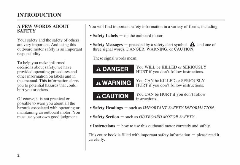
You will find important safety information in a variety of forms, including:
This entire book is filled with important safety information please read itcarefully.
preceded by a safety alert symbol and one ofthree signal words, DANGER, WARNING, or CAUTION.
These signal words mean:
such as
on the outboard motor.
such as
how to use this outboard motor correctly and safely.
You WILL be KILLED or SERIOUSLYHURT if you don’t follow instructions.
You CAN be KILLED or SERIOUSLYHURT if you don’t follow instructions.
You CAN be HURT if you don’t followinstructions.
04/01/30 10:15:19 31ZY0600_003

3
CONTENTS
...................................OUTBOARD MOTOR SAFETY . 7................IMPORTANT SAFETY INFORMATION . 7
................................SAFETY LABEL LOCATIONS . 9
..................................CONTROLS AND FEATURES . 10CONTROL AND FEATURE
................................IDENTIFICATION CODES . 10....COMPONENT AND CONTROL LOCATIONS . 14
..............................................................CONTROLS . 19H Type (tiller handle)
....................Engine Stop Switch and Switch Clip . 19
....................Choke Knob (H type manual choke) . 19..........................................................Throttle Grip . 20
.....................................Throttle Friction Adjuster . 20.....................................................Gearshift Lever . 20
................................................Recoil Starter Grip . 21Electric Starter Button
.............(models equipped with electric starter) . 21.........................................Steering Friction Lever . 21
....................................Power Tilt Switch (T type) . 22................................................Tilt Lever (G type) . 22
R Type (remote control)......................................................Ignition Switch . 23
.............Switch Clip and Emergency Stop Switch . 23.......................................................Fast Idle Lever . 24
..........................Gearshift/Throttle Control Lever . 25....................................Power Tilt Switch (T type) . 26
...............................Manual Relief Valve (T type) . 26...........................Tilt Lock Lever (G and T types) . 27
Common Controls..............................................Engine Cover Latch . 27
.............................Transom Angle Adjusting Rod . 27..................................Tilt Lever (manual tilt type) . 28
.......................................................INSTRUMENTS . 29............................................................Fuel Gauge . 29
.........................Tachometer (optional equipment) . 29...........................................................INDICATORS . 30
...............Oil Pressure Indicator (R type) (H type) . 30..................................Overheat Indicator (R type) . 30
.....................................Cooling System Indicator . 31................................................OTHER FEATURES . 31
.....................................................Overrev Limiter . 31Automatic Choke
.............(models equipped with electric starter) . 31...................................................................Anodes . 31
................................................Portable Fuel Tank . 32.............................................Fuel Cap Vent Knob . 32
.................................................Fuel Priming Bulb . 32
04/01/30 10:15:23 31ZY0600_004

?
?
4
CONTENTS
..........................................................INSTALLATION . 33.....................................POWER REQUIREMENTS . 33
...................BOAT TRANSOM REQUIREMENTS . 33..................................INSTALLATION POSITION . 33
.......................................................ATTACHMENT . 34.....................TRANSOM ANGLE ADJUSTMENT . 35
...................................BATTERY CONNECTIONS . 35
................................................BEFORE OPERATION . 38.....ARE YOU READY TO GET UNDER WAY . 38
IS YOUR OUTBOARD MOTOR................................................READY TO GO . 38
................................................................OPERATION . 40....................SAFE OPERATING PRECAUTIONS . 40
.......................................BREAK-IN PROCEDURE . 40.....................TRANSOM ANGLE ADJUSTMENT . 41
.......................................PORTABLE FUEL TANK . 43................................FUEL HOSE CONNECTIONS . 43
.......................................................FUEL PRIMING . 44......................................STARTING THE ENGINE . 44
............................................H Type (tiller handle) . 44........................................R Type (remote control) . 47
.....................................EMERGENCY STARTING . 49.......................................STOPPING THE ENGINE . 52
................................Emergency Engine Stopping . 52.......................................Normal Engine Stopping . 52
GEARSHIFT AND..............................THROTTLE OPERATION . 54
............................................H Type (tiller handle) . 54........................................R Type (remote control) . 55
...............................................................STEERING . 56............................................H Type (tiller handle) . 56
........................................R Type (remote control) . 56................................................................CRUISING . 57
........................SHALLOW WATER OPERATION . 59...............MOORING, BEACHING, LAUNCHING . 62
04/01/30 10:15:27 31ZY0600_005
5
CONTENTS
..............SERVICING YOUR OUTBOARD MOTOR . 64...........THE IMPORTANCE OF MAINTENANCE . 64
.....................................MAINTENANCE SAFETY . 65TOOL KIT AND EMERGENCY STARTER
.....................................................................ROPE . 66...............................MAINTENANCE SCHEDULE . 67
......................MANUAL RELIEF VALVE (T type) . 69ENGINE COVER REMOVAL AND
..................................................INSTALLATION . 69............................................Engine Oil Level Check . 70
....................................................Engine Oil Change . 71.......................................................Oil Filter Change . 72
..................................Engine Oil Recommendations . 73................................................Gear Oil Level Check . 73
........................................................Gear Oil Change . 74.....................................................Lubrication Points . 76....................................................Spark Plug Service . 77
.............................................................REFUELING . 79...............................FUEL RECOMMENDATIONS . 80
.........Fuel Pump Filter Inspection and Replacement . 80....................Portable Fuel Tank and Filter Cleaning . 82
.................................Recoil Starter Rope Inspection . 83..................................................Anode Replacement . 83
..............................................Propeller Replacement . 84
....................................................................STORAGE . 85...................................STORAGE PREPARATION . 85
..........................................Cleaning and Flushing . 85........................................................................Fuel . 87
.............................................................Engine Oil . 89...................................STORAGE PRECAUTIONS . 89
...............................REMOVAL FROM STORAGE . 90
........................................................TRANSPORTING . 91WITH OUTBOARD MOTOR INSTALLED
.............................................................ON BOAT . 91WITH OUTBOARD MOTOR REMOVED
.......................................................FROM BOAT . 91
TAKING CARE OF UNEXPECTED..........................................................PROBLEMS . 92
BATTERY WILL NOT CHARGE AND.ELECTRIC STARTER WILL NOT OPERATE . 97
OIL PRESSURE INDICATOR LIGHT GOES OFF...................AND ENGINE SPEED IS LIMITED . 98
OVERHEAT AND ENGINE SPEED IS..............................................................LIMITED . 99
........................................SUBMERGED MOTOR . 101
04/01/30 10:15:31 31ZY0600_006

6
CONTENTS
TECHNICAL AND CONSUMER.................................................INFORMATION . 103
.............................TECHNICAL INFORMATION . 103......................................Serial Number locations . 103
Carburetor Modification for High Altitude.........................................................Operation . 104
................................................Oxygenated Fuels . 105...............Emission Control System Information . 106
............................................................Star Label . 108......................................................Specifications . 110
.............................CONSUMER INFORMATION . 118.............................................Honda Publications . 118
............................Warranty Service Information . 118
.........................................................................INDEX . 119
.........................WIRING DIAGRAMS . Inside back cover
This Owner’s Manual is using the following type nameswhen it describes the operations special to a type.
Tiller handle type:Remote control type:Gas assist type:Power tilt type:
Check the type of your outboard motor and read thisOwner’s Manual thoroughly before operation.Texts with no type indication are the information and/orprocedures common to all types.
H typeR typeG typeT type
04/01/30 10:15:39 31ZY0600_007
7
IMPORTANT SAFETYINFORMATION
Operator Responsibility
OUTBOARD MOTOR SAFETY
It is the operator’s responsibility toprovide the necessary safeguardsto protect people and property.Know how to stop the enginequickly in case of emergency.Understand the use of all controls.
Attach the emergency stop switchlanyard securely to the operator.
Stop the engine immediately ifanyone falls overboard, and do notrun the engine while the boat isnear anyone in the water.
Always stop the engine if youmust leave the controls for anyreason.
Always wear a PFD (PersonalFlotation Device) while on theboat.
Familiarize yourself with all lawsand regulations relating to boatingand the use of outboard motors.
Be sure that anyone who operatesthe outboard motor receives properinstruction.
Be sure the outboard motor isproperly mounted on the boat.
Do not remove the engine coverwhile the engine is running.
Most accidents can be prevented ifyou follow all instructions in thismanual and on the outboard motor.The most common hazards arediscussed below, along with the bestway to protect yourself and others.
Honda BF8D/BFP8D/BF9.9D/BFP9.9D/BF15D/BFP15D/BF20Dand BFP20D outboard motors aredesigned for use with boats that havea suitable manufacturer’s powerrecommendation. Other uses canresult in injury to the operator ordamage to the outboard motor andother property.
04/01/30 10:15:50 31ZY0600_008
8
Carbon Monoxide HazardRefuel With Care
OUTBOARD MOTOR SAFETY
Exhaust gas contains poisonouscarbon monoxide. Avoid inhalationof exhaust gas. Never run the enginein a closed garage or confined area.
Gasoline is extremely flammable,and gasoline vapor can explode.Refuel outdoors, in a well-ventilated area, with the enginestopped. Never smoke neargasoline, and keep other flamesand sparks away.
Remove any portable fuel tankfrom the boat for refueling. Keepthe portable fuel tank away fromthe battery or other potential sparksources.
Refuel carefully to avoid spillingfuel. Avoid overfilling the fueltank.
After refueling, tighten the fillercap securely. If any fuel is spilled,make sure the area is dry beforestarting the engine.
04/01/30 10:15:57 31ZY0600_009

9
SAFETY LABEL LOCATIONS
OUTBOARD MOTOR SAFETY
The labels shown here contain important safety information. Please read them carefully. These labels are consideredpermanent parts of your outboard motor. If a label comes off or becomes hard to read, contact an authorized HondaMarine servicing dealer for a replacement.
04/01/30 10:16:12 31ZY0600_010
* *
*
10
CONTROL AND FEATURE IDENTIFICATION CODES
CONTROLS AND FEATURES
Electric StarterRemote ControlTiller HandleShaft Length
Gas assist TiltPower TiltPower Thrust PropellerBattery Charging DCReceptacleTachometer
Type
Model
SHA
SH
LHA
LH
SHSA
SH
S
LHSA
LH
S
LRA
L
RS
BF8D
LHA
LH
P
XHA
XH
P
XHSA
XH
S
P
BFP8D
LHTA
LH
S
TP
XRTA
X
RS
TP
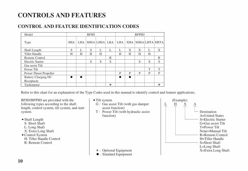
Refer to this chart for an explanation of the Type Codes used in this manual to identify control and feature applications.
Optional EquipmentStandard Equipment
BF8D/BFP8D are provided with thefollowing types according to the shaftlength, control system, tilt system, and startsystem.
Shaft LengthS: Short ShaftL: Long ShaftX: Extra Long ShaftControl SystemH: Tiller Handle ControlR: Remote Control
Tilt systemGas assist Tilt (with gas damperassist function)Power Tilt (with hydraulic assistfunction)
DestinationA=United StatesS=Electric Starter
L=Long ShaftS=Short ShaftH=Tiller HandleR=Remote Control
(Example)L H S A
X=Extra Long Shaft
T=Power Tilt
G :
T :
::
G=Gas assist Tilt
None=Manual Tilt
04/01/30 10:16:39 31ZY0600_011

*** *
*
11
Electric StarterRemote ControlTiller HandleShaft Length
Gas assist Tilt
Battery Charging DCReceptacle
Power Thrust Propeller
Model
Type
Tachometer
Power Tilt
BFP9.9DBF9.9D
XHTA
XH
S
TP
XRTA
X
RS
TP
LRTA
L
RS
TP
XHSA
XH
S
P
XHA
XH
P
LHA
LH
P
LRA
L
RS
LHSA
LH
S
SHSA
SH
S
LHA
LH
SHA
SH
LHTA
LH
S
TP
LRA
L
RS
P
Refer to this chart for an explanation of the Type Codes used in this manual to identify control and feature applications.
Optional EquipmentStandard Equipment
BF9.9D/BFP9.9D are provided with thefollowing types according to the shaftlength, control system, tilt system, and startsystem.
Shaft LengthS: Short ShaftL: Long ShaftX: Extra Long Shaft
Tilt systemGas assist Tilt (with gas damperassist function)Power Tilt (with hydraulic assistfunction)
Control SystemH: Tiller Handle ControlR: Remote Control
DestinationA=United StatesS=Electric Starter
L=Long ShaftS=Short ShaftH=Tiller HandleR=Remote Control
(Example)L H S A
X=Extra Long Shaft
T=Power Tilt
G :
T :
::
G=Gas assist Tilt
None=Manual Tilt
04/01/30 10:17:08 31ZY0600_012

* * * * *
*
12
Electric StarterRemote ControlTiller HandleShaft Length
Power TiltGas assist Tilt
Battery Charging DCReceptacle
Power Thrust Propeller
Tachometer
LHSA
LH
S
LRA
L
RS
SHGA
SH
SG
LHGA
LH
SG
XHGA
XH
SG
SRTA
S
RS
T
LRTA
L
RS
T
LRTA
L
RS
TP
Model BFP15D
Type LGA
LH
G
XRTA
X
RS
TP
SHA
SH
SHSA
SH
S
LHA
LH
XHA
XH
XHTA
XH
S
TP
SHTA
LH
S
T
BF15D
LHTA
LH
S
T
Refer to this chart for an explanation of the Type Codes used in this manual to identify control and feature applications.
BF20D/BFP20D are provided with thefollowing types according to the shaftlength, control system, tilt system, and startsystem.
Optional EquipmentStandard Equipment
Shaft LengthS: Short ShaftL: Long ShaftX: Extra Long ShaftControl SystemH: Tiller Handle ControlR: Remote Control
Tilt systemGas assist Tilt (with gas damperassist function)Power Tilt (with hydraulic assistfunction)
DestinationA=United StatesS=Electric Starter
L=Long ShaftS=Short ShaftH=Tiller HandleR=Remote Control
(Example)L H S A
X=Extra Long Shaft
T=Power Tilt
G :
T :
::
G=Gas assist Tilt
None=Manual Tilt
04/01/30 10:17:39 31ZY0600_013

* * * * *
*
13
Model
Electric StarterRemote ControlTiller HandleShaft Length
Type SHSA
SH
S
LHSA
LH
S
XHSA
XH
S
Power TiltGas assist Tilt
SHTA
SH
S
T
XHTA
XH
S
T
XHGA
XH
SG
LHGA
LH
SG
SHGA
SH
SG
Battery Charging DCReceptacle
Power Thrust Propeller
SHA
SH
LHA
LH
SRA
S
RS
LRA
L
RS
LGA
LH
G
SRTA
S
RS
T
LRTA
L
RS
T
LRTA
L
RS
TP
Tachometer
BF20D
LHTA
LH
S
T
Refer to this chart for an explanation of the Type Codes used in this manual to identify control and feature applications.
BF20D/BFP20D are provided with thefollowing types according to the shaftlength, control system, tilt system, and startsystem.
Optional EquipmentStandard Equipment
Shaft LengthS: Short ShaftL: Long ShaftX: Extra Long ShaftControl SystemH: Tiller Handle ControlR: Remote Control
Tilt systemGas assist Tilt (with gas damperassist function)Power Tilt (with hydraulic assistfunction)
DestinationA=United StatesS=Electric Starter
L=Long ShaftS=Short ShaftH=Tiller HandleR=Remote Control
(Example)L H S A
X=Extra Long Shaft
T=Power Tilt
G :
T :
::
G=Gas assist Tilt
None=Manual Tilt
BFP20D
04/01/30 10:18:09 31ZY0600_014

14
H Type (tiller handle)COMPONENT AND CONTROL LOCATIONS
CONTROLS AND FEATURES
ENGINE OILDRAIN SCREW
PROPELLER
EXHAUST PORT
RECOIL STARTER GRIP
OIL FILLER CAP SHIFT LEVER
TILT LEVER(G type only)
ENGINE COVER
ANODES
GEAR OILLEVEL PLUG
COOLING SYSTEMINDICATOR
OIL LEVELDIPSTICK
TILLER HANDLE
ELECTRIC STARTER BUTTON(electric starter type only)
FLUSH PORT HOLE(inside engine cover)
STERN BRACKET
ANTIVENTILATIONPLATE
GEAR OIL DRAIN/FILL PLUG
COOLING WATERINTAKE PORT
TRANSOM ANGLEADJUSTING ROD
CLAMP SCREW
MANUALRELIEF VALUE(T type only)
TILT LEVER(manual tilt type only)
04/01/30 10:18:15 31ZY0600_015

15
CONTROLS AND FEATURES
SWITCH CLIP
CHOKE KNOB (equipped type only)
OIL PRESSURE INDICATOR LIGHT
THROTTLE FRICTIONADJUSTER
THROTTLE GRIP
FUEL HOSE CONNECTOR
STEERING FRICTION LEVER
POWER TILT SWITCH(T type only)
ENGINE STOP SWITCH
LANYARD
04/01/30 10:18:20 31ZY0600_016
16
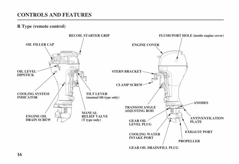
R Type (remote control)
CONTROLS AND FEATURES
OIL FILLER CAP
OIL LEVELDIPSTICK
ENGINE OILDRAIN SCREW
ENGINE COVER
COOLING WATERINTAKE PORT
PROPELLER
ANTIVENTILATIONPLATE
RECOIL STARTER GRIP
ANODES
GEAR OILLEVEL PLUG
COOLING SYSTEMINDICATOR
MANUALRELIEF VALVE(T type only)
FLUSH PORT HOLE (inside engine cover)
STERN BRACKET
CLAMP SCREW
TRANSOM ANGLEADJUSTING ROD
EXHAUST PORT
GEAR OIL DRAIN/FILL PLUG
TILT LEVER(manual tilt type only)
04/01/30 10:18:27 31ZY0600_017

17
CONTROLS AND FEATURES
SWITCH CLIP
REMOTE CONTROLFRICTION ADJUSTER
LANYARD
GEARSHIFT/THROTTLE CONTROL LEVER
NEUTRAL RELEASE LEVER
OIL PRESSURE INDICATOR LIGHT
OVERHEATING INDICATOR LIGHT
FAST IDLE LEVER
BUZZER (inside box)
IGNITION SWITCH
EMERGENCY STOP SWITCH
SPARE SWITCH CLIP
POWER TILT SWITCH(T type only)
04/01/30 10:18:31 31ZY0600_018
18
CONTROLS AND FEATURES
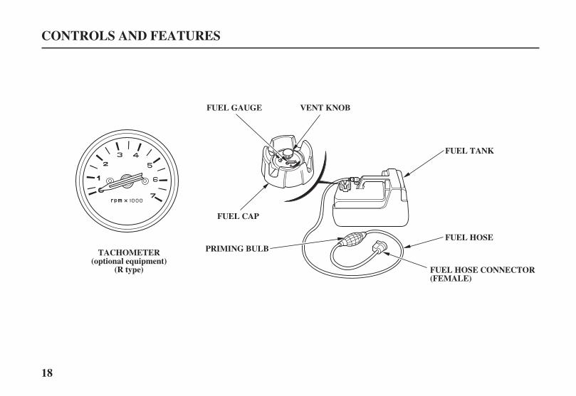
FUEL GAUGE VENT KNOB
FUEL CAP
PRIMING BULB
FUEL HOSE CONNECTOR(FEMALE)
FUEL TANK
FUEL HOSE
TACHOMETER(optional equipment)
(R type)
04/01/30 10:18:36 31ZY0600_019
19
CONTROLS
H Type (tiller handle)
CONTROLS AND FEATURES
ENGINE STOPSWITCH
LANYARD
SWITCH CLIP
CHOKE KNOB
LANYARD
OOPPEENN
CCLLOOSSEEDD
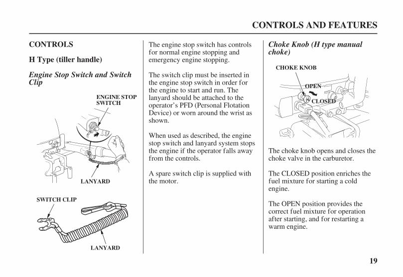
Engine Stop Switch and SwitchClip
Choke Knob (H type manualchoke)
The engine stop switch has controlsfor normal engine stopping andemergency engine stopping.
The switch clip must be inserted inthe engine stop switch in order forthe engine to start and run. Thelanyard should be attached to theoperator’s PFD (Personal FlotationDevice) or worn around the wrist asshown.
When used as described, the enginestop switch and lanyard system stopsthe engine if the operator falls awayfrom the controls.
The CLOSED position enriches thefuel mixture for starting a coldengine.
The OPEN position provides thecorrect fuel mixture for operationafter starting, and for restarting awarm engine.
The choke knob opens and closes thechoke valve in the carburetor.
A spare switch clip is supplied withthe motor.
04/01/30 10:18:49 31ZY0600_020

20
CONTROLS AND FEATURES
THROTTLE GRIP
RELEASE
FIX
THROTTLE GRIP
THROTTLE INDEXMARK R (reverse) N (neutral)THROTTLE
FRICTIONADJUSTER F (forward)
Throttle Grip Gearshif t LeverThrottle Friction Adjuster
The gearshift lever is used to select F(forward), N (neutral), or R (reverse)gears.
The throttle grip controls enginespeed.
An index mark on the tiller armshows throttle position and is helpfulfor setting the throttle correctly whenstarting (p. ).
If the gearshift lever is in the F(forward) or R (reverse) position, therecoil starter will not operate, and theelectric starter button (applicablemodels) will not operate the startermotor.
The engine can be started with thegearshift lever in the N (neutral)position only.
The throttle friction adjuster adjustsresistance to throttle grip rotation.
Turn the adjuster clockwise toincrease friction for holding a throttlesetting while cruising.
Turn the adjuster counterclockwise todecrease friction for easy throttle griprotation.
45
04/01/30 10:19:03 31ZY0600_021
21
CONTROLS AND FEATURES
STARTER GRIP
ELECTRIC STARTERBUTTON
FFRREEEELLOOCCKK
STEERING FRICTION LEVER
SWITCHCLIP
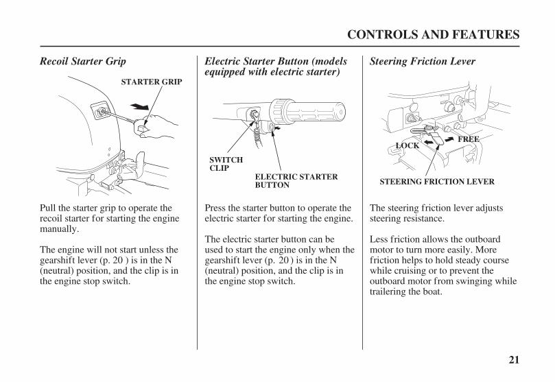
Recoil Starter Grip Electric Starter Button (modelsequipped with electric starter)
Steering Friction Lever
Pull the starter grip to operate therecoil starter for starting the enginemanually.
Press the starter button to operate theelectric starter for starting the engine.
The steering friction lever adjustssteering resistance.
Less friction allows the outboardmotor to turn more easily. Morefriction helps to hold steady coursewhile cruising or to prevent theoutboard motor from swinging whiletrailering the boat.
The electric starter button can beused to start the engine only when thegearshift lever (p. ) is in the N(neutral) position, and the clip is inthe engine stop switch.
The engine will not start unless thegearshift lever (p. ) is in the N(neutral) position, and the clip is inthe engine stop switch.
20 20
04/01/30 10:19:15 31ZY0600_022

22
CONTROLS AND FEATURES
Power tilt is a convenience fortilting the motor, shallow wateroperation, and trailer only. It is notdesigned to be used as a trimfunction to adjust the trim angleof the boat.
TILT LEVER
POWER TILT SWITCH
Press UPto tilt themotor up.
Press DN to tiltthe motor down.
TTIILLTT
RRUUNN((LLOOCCKK))
Power Tilt Switch (T type) Tilt Lever (G type)(gas assist tilt type)
Moving the tilt lever to the TILTposition allows the outboard motor tobe tilted and moving the tilt lever tothe RUN (LOCK) position locks theoutboard motor in the desiredposition. Use the tilt lever totemporarily tilt the outboard motorwhen the boat is operating in shallowwater, or mooring in shallow water.The tilt lever must be in the RUN(LOCK) position before operatingthe outboard motor or the motorcould tilt up when operating inreverse.
The rocker type power tilt switch hasUP and DN (down) positions forchanging the angle of the outboardmotor.
During shallow water operation,beaching, launching, or mooring,proceed at low speed with a smallthrottle opening and tilt the motor upas necessary (p. ).59
04/01/30 10:19:26 31ZY0600_023

23
R Type (remote control)
CONTROLS AND FEATURES
LANYARD
SWITCH CLIP
SWITCH CLIP
LANYARD
EMERGENCYSTOP SWITCH
IGNITIONSWITCH
EMERGENCY STOPSWITCH
OOFFFFOONN
SSTTAARRTT
SWITCH CLIP
Switch Clip and Emergency StopSwitch (side-mount type)
Ignition Switch (side-mounttype)
Turning the ignition switch key to theSTART position operates the startermotor. The key automatically returnsto the ON position when releasedfrom the START position.
The ignition switch can be used tostart the engine only when thegearshift lever (p. ) is in the N(neutral) position, and the switch clipis in the emergency stop switch.
Turning the ignition switch to theOFF position stops the engine.
For panel-mount or top-mountremote control information, refer tothe instructions provided with theremote control equipment.
The ignition switch controls theignition system and starter motor.
20
04/01/30 10:19:37 31ZY0600_024
24
CONTROLS AND FEATURES
FAST IDLE LEVER
MAXIMUM FAST IDLE
LOWEST POSITION
SPARE SWITCH CLIP
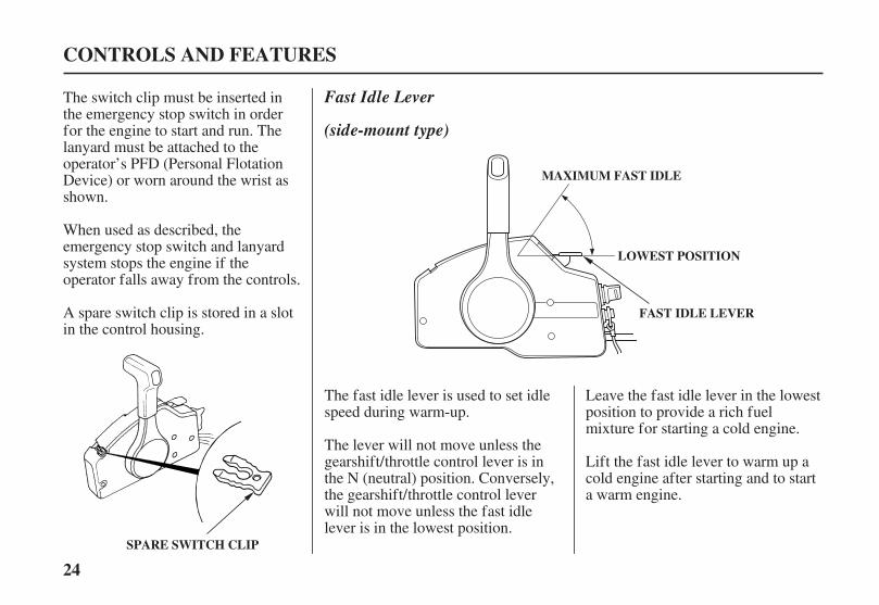
Fast Idle Lever
(side-mount type)
Leave the fast idle lever in the lowestposition to provide a rich fuelmixture for starting a cold engine.
Lift the fast idle lever to warm up acold engine after starting and to starta warm engine.
The switch clip must be inserted inthe emergency stop switch in orderfor the engine to start and run. Thelanyard must be attached to theoperator’s PFD (Personal FlotationDevice) or worn around the wrist asshown.
When used as described, theemergency stop switch and lanyardsystem stops the engine if theoperator falls away from the controls.
A spare switch clip is stored in a slotin the control housing.
The fast idle lever is used to set idlespeed during warm-up.
The lever will not move unless thegearshift/throttle control lever is inthe N (neutral) position. Conversely,the gearshift/throttle control leverwill not move unless the fast idlelever is in the lowest position.
04/01/30 10:19:50 31ZY0600_025

25
CONTROLS AND FEATURES
GEARSHIFT/THROTTLECONTROL LEVER
N (neutral)
R (reverse)F (forward)
EENNGGIINNEESSPPEEEEDD
EENNGGIINNEESSPPEEEEDD
GEARSHIFT/THROTTLECONTROL LEVER
NEUTRAL RELEASE LEVER
HIGH
HIGH
Gearshif t/Throttle ControlLever (side-mount type)
The gearshift/throttle control levercontrols engine speed and selects F(forward), N (neutral), or R (reverse)gears.
Moving the control lever 30° from N(neutral) selects the gear, and furthermovement increases engine speed.
A friction adjuster near the base ofthe control lever adjusts the operatingresistance of the control lever (p. ).
Less friction allows easier controllever movement. More friction helpsto hold a steady throttle setting whilecruising.
The control lever automatically locksitself in the N (neutral) position. Tomove the lever out of the N (neutral)position, you must squeeze theneutral release lever on the undersideof the lever handle.
55
04/01/30 10:20:00 31ZY0600_026

※
※
26
CONTROLS AND FEATURES
Power tilt is a convenience fortilting the motor, shallow wateroperation, and trailer only. It is notdesigned to be used as a trimfunction to adjust the trim angle ofthe boat.
:
MANUAL RELIEF VALVE
POWER TILT SWITCH
CONTROL LEVERPress UP to tiltthe motor up.
Press DN to tiltthe motor down.
MANUAL(Valve closedto fix)
POWER(Valve opento release)
RIGHT STERN BRACKET(side-mount type)Power Tilt Switch (T type) Manual Relief Valve (T type)
The outboard motor can be tiltedmanually after opening the manualrelief valve. This allows the outboardmotor to be tilted when no battery isconnected.
Do not turn this screw. If thisscrew is turned hydraulic oilwill bleed out of the power tiltsystem. Should this happen itwill be necessary to consult yourauthorized Honda Marine dealerand have the system refilled.
The rocker type power tilt switch islocated on the control lever and hasUP and DN (down) positions forchanging the angle of the outboardmotor.
During shallow water operation,beaching, launching, or mooring,proceed at low speed with a smallthrottle opening and tilt the motor upas necessary (p. ).59
04/01/30 10:20:11 31ZY0600_027

27
Common Controls
Engine Cover Latch
Transom Angle Adjusting Rod
CONTROLS AND FEATURES
LLOOCCKK
FFRREEEE
EENNGGIINNEE CCOOVVEERR LLAATTCCHH
TTIILLTT LLOOCCKKLLEEVVEERR
ADJUSTING ROD
(manual tilt SH type/LH type)
Tilt Lock Lever(G and T types)
The tilt lock lever is used to supportthe outboard motor in the fully-raisedposition.
When the boat is to be moored for along time, tilt the outboard motor asfar as it will go. Then move the tiltlock lever to the LOCK position, andgently lower the outboard motor untilthe lever contacts the stern bracket.
The engine cover latch fastens theengine cover to the outboard motor.
The transom angle adjusting rodlimits the tilt angle of the outboardmotor when fully lowered.
04/01/30 10:20:24 31ZY0600_028
28
CONTROLS AND FEATURES
ADJUSTING ROD
RRUUNN((LLOOCCKK))
TTIILLTT
TILT LEVER
ADJUSTING ROD(storage location)
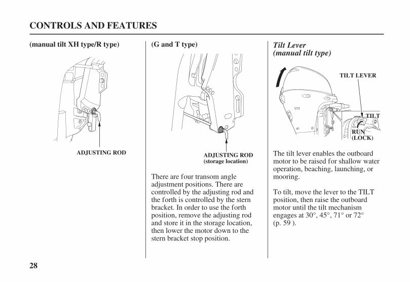
(G and T type)(manual tilt XH type/R type) Tilt Lever(manual tilt type)
The tilt lever enables the outboardmotor to be raised for shallow wateroperation, beaching, launching, ormooring.
To tilt, move the lever to the TILTposition, then raise the outboardmotor until the tilt mechanismengages at 30°, 45°, 71° or 72°(p. ).
There are four transom angleadjustment positions. There arecontrolled by the adjusting rod andthe forth is controlled by the sternbracket. In order to use the forthposition, remove the adjusting rodand store it in the storage location,then lower the motor down to thestern bracket stop position.
59
04/01/30 10:20:32 31ZY0600_029

29
INSTRUMENTS
Fuel Gauge
Tachometer(optional equipment)(R Type)
CONTROLS AND FEATURES
FUEL GAUGE
TACHOMETERA fuel gauge is built into the cap ofthe portable fuel tank.
The tachometer shows engine speedin revolutions per minute.
BF15D/BFP15D/BF20D/BFP20D71° : Tiller handle S type.72° : Tiller handle L and X types and
Remote control type.
BF8D/BFP8D/BF9.9D/BFP9.9D71° : Tiller handle S and L types.72° : Tiller handle X type and
Remote control type.
04/01/30 10:20:42 31ZY0600_030

30
INDICATORS
(H type)
Oil Pressure Indicator(R type)
Overheat Indicator(R type only)
CONTROLS AND FEATURES
(GREEN)
OIL PRESSURE INDICATOR LIGHT
(RED)
(R type)
(H type)
When the green light is lit, oilpressure is OK.
If oil pressure becomes low, thegreen light will go off, and theengine protection system will limitengine speed. Refer to TAKINGCARE OF UNEXPECTEDPROBLEMS, p. .
Low oil pressure indicates that theengine oil level is low, or that there isa problem with the engine lubricationsystem.
Remote controls are also equippedwith a buzzer that sounds when thegreen light goes off.The buzzer sound stops below anengine speed of 1,400 rpm.
When the overheat protection systemis activated, the red overheat lightwill come on a buzzer will sound andthe engine speed will be reduced to1,800 rpm. If the condition persistsfor another 20 seconds, the enginewill shut off. Refer to TAKINGCARE OF UNEXPECTEDPROBLEMS, p. .
Engine overheating may be the resultof clogged water intakes.
When the overheat protection systemis activated, the engine speed will bereduced to 1,800 rpm. If thecondition persists for another 20seconds, the engine will shut off.Refer to TAKING CARE OFUNEXPECTED PROBLEMS, p. .
99
99
98
04/01/30 10:20:56 31ZY0600_031

31
Cooling System Indicator OTHER FEATURES
Overrev Limiter
Anodes
Automatic Choke (modelsequipped with electric starter)
CONTROLS AND FEATURES
COOLING SYSTEM INDICATOR ANODES (each side)
ANODE(G and T types only)
Water should flow from the coolingsystem indicator while the engine isrunning. This shows that water iscirculating through the coolingsystem.
If water stops flowing while theengine is running, that indicates acooling system problem, such asclogged water intakes, which willcause engine overheating.
The engine is equipped with anoverrev limiter to prevent thepossibility of mechanical damagefrom excessive engine speed.
The overrev limiter may be activatedduring operation, limiting enginespeed, if the outboard motor is tiltedexcessively, or when propellerventilation occurs during a sharp turn.
If the overrev limiter is activated,check the trim angle of the outboardmotor.
The engine is equipped with anautomatic choke so that the chokesystem operation is not needed whenstarting the engine.
The anodes are made of a sacrificialmaterial that helps to protect theoutboard motor from corrosion.
There are two anodes on the gearcase, one on the stern bracket.
04/01/30 10:21:12 31ZY0600_032
32
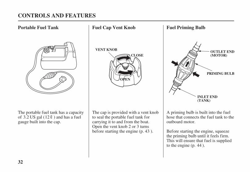
Portable Fuel Tank Fuel Cap Vent Knob Fuel Priming Bulb
CONTROLS AND FEATURES
VENT KNOB
OOPPEENN
PRIMING BULB
INLET END(TANK)
CLOSEOUTLET END(MOTOR)
The portable fuel tank has a capacityof US gal ( ) and has a fuelgauge built into the cap.
The cap is provided with a vent knobto seal the portable fuel tank forcarrying it to and from the boat.Open the vent knob 2 or 3 turnsbefore starting the engine (p. ).
A priming bulb is built into the fuelhose that connects the fuel tank to theoutboard motor.
Before starting the engine, squeezethe priming bulb until it feels firm.This will ensure that fuel is suppliedto the engine (p. ).
123.2
43
44
04/01/30 10:21:24 31ZY0600_033

-
--
--
17.0 in (433 mm)22.2 in (563 mm)27.7 in (703 mm)
33
POWER REQUIREMENTS
BOAT TRANSOMREQUIREMENTS
INSTALLATION POSITION
INSTALLATION
CENTER LINE
0 2.0 in(0 50 mm)
TTRRAANNSSOOMM HHEEIIGGHHTT
IIDDLLEEPPOORRTT
Correct and secure installation isessential for safe boating and goodperformance. Follow the installationinstructions provided in this manual.
Before installation, check to be surethat the outboard motor does notexceed the recommended maximumhorsepower for the boat on which itis to be installed. Refer to the boat’scertification plate for recommendedmaximum horsepower. If thecertification plate information is notavailable, contact the boat dealer ormanufacturer.
For most applications, the outboardmotor should have a horsepowerrating which provides 80% of themaximum recommended horsepowerfor the boat.
The antiventilation plate of theoutboard motor should be 0 2.0inches below the bottom of the boat.
Install the outboard motor on thecenter of the boat transom.
Honda BF8D/BFP8D/BF9.9D/BFP9.9D/BF15D/BFP15D/BF20Dand BFP20D outboard motors can beinstalled on a boat transom having athickness range of 1.3 2.2 inches(35 57 mm).
Transom HeightType:S:L:X:
When the outboard motor is installedextremely low, the idle port may beimmersed and the engine maybecome hard to start or may runpoorly. Check that the idle port ishigh enough from the water levelwhen the engine is stopped with theboat fully loaded.
04/01/30 10:21:38 31ZY0600_034
34
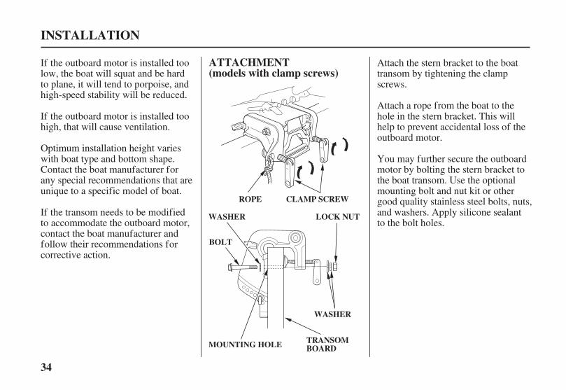
ATTACHMENT(models with clamp screws)
INSTALLATION
CLAMP SCREW
WASHER
BOLT
LOCK NUT
MOUNTING HOLE
WASHER
TRANSOMBOARD
ROPE
If the outboard motor is installed toolow, the boat will squat and be hardto plane, it will tend to porpoise, andhigh-speed stability will be reduced.
If the outboard motor is installed toohigh, that will cause ventilation.
Optimum installation height varieswith boat type and bottom shape.Contact the boat manufacturer forany special recommendations that areunique to a specific model of boat.
If the transom needs to be modifiedto accommodate the outboard motor,contact the boat manufacturer andfollow their recommendations forcorrective action.
Attach the stern bracket to the boattransom by tightening the clampscrews.
Attach a rope from the boat to thehole in the stern bracket. This willhelp to prevent accidental loss of theoutboard motor.
You may further secure the outboardmotor by bolting the stern bracket tothe boat transom. Use the optionalmounting bolt and nut kit or othergood quality stainless steel bolts, nuts,and washers. Apply silicone sealantto the bolt holes.
04/01/30 10:21:50 31ZY0600_035
-
35
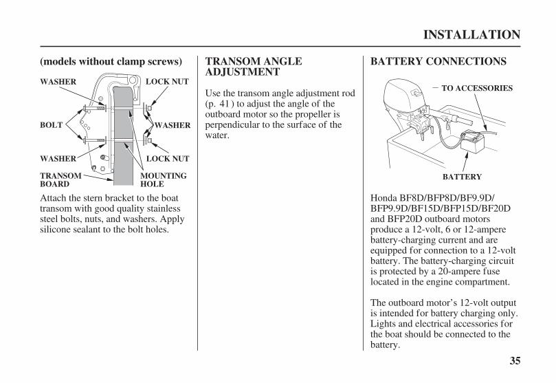
BATTERY CONNECTIONSTRANSOM ANGLEADJUSTMENT
(models without clamp screws)
INSTALLATION
TO ACCESSORIES
BATTERY
LOCK NUT
WASHER
BOLT
LOCK NUT
TRANSOMBOARD
WASHER
MOUNTINGHOLE
WASHER
Honda BF8D/BFP8D/BF9.9D/BFP9.9D/BF15D/BFP15D/BF20Dand BFP20D outboard motorsproduce a 12-volt, 6 or 12-amperebattery-charging current and areequipped for connection to a 12-voltbattery. The battery-charging circuitis protected by a 20-ampere fuselocated in the engine compartment.
The outboard motor’s 12-volt outputis intended for battery charging only.Lights and electrical accessories forthe boat should be connected to thebattery.
Use the transom angle adjustment rod(p. ) to adjust the angle of theoutboard motor so the propeller isperpendicular to the surface of thewater.
Attach the stern bracket to the boattransom with good quality stainlesssteel bolts, nuts, and washers. Applysilicone sealant to the bolt holes.
41
04/01/30 10:22:00 31ZY0600_036

-
--
12V-35Ah (CCA 270)
36
Battery
Minimum Requirements
Plug and Receptacle(models without electric starter)
Types With Electric Starter
Types With Manual Start
INSTALLATION
COVER
TO ACCESSORIESBATTERY
DC RECEPTACLE
TTOO BBAATTTTEERRYY
For complete information, refer tothe battery manufacturer’sinstructions.
To prepare the outboard motor forconnection to a battery, pull the coverout of the DC receptacle, connectyour battery charging wires to thereceptacle. Attach the connected DCreceptacle on the holder on the tillerarm.
The receptacle is provided with acover, which should be attachedwhen the plug is removed, in order tokeep the receptacle clean and dry.
The battery should be kept in acorrosion-resistant battery box that issecurely mounted in a location awayfrom the fuel tank and protectedfrom water and direct sunlight.
These types are equipped withbattery cables. The positive (+) cablehas a red band at the batteryconnector. The negative (-) cable hasa black band at the battery connector.
For electric starter operation, use a12-volt battery with an ampere-hourrating of at least 35 Ah (CCA 270).
These types are equipped with a 12-volt DC battery-charging receptaclewhich can be wired to a 12-voltbattery to power lights and electricalaccessories for the boat.
04/01/30 10:22:13 31ZY0600_037

-
+
37
Battery Terminals
INSTALLATION
BLACK or GREEN
( ) TERMINAL
( ) TERMINAL
RED
Be caref ul to avoid connecting thebattery in reverse polarity, as thatwill damage the battery-chargingsystem in the outboard motor.
Connect the positive (+) battery cableto the positive (+) battery terminal,then connect the negative (-) batterycable to the negative (-) batteryterminal.
The negative (-) battery cable shouldalways be removed from the batterywhen connecting or disconnectingthe positive (+) battery cable, so toolscannot cause a short circuit if theytouch a grounded part while beingused on the positive (+) batteryterminal fitting.
04/01/30 10:22:20 31ZY0600_038

Improperly maintainingthis outboard motor, orfailing to correct a problembefore operation, couldcause a malfunction inwhich you could beseriously injured.
Always perform apreoperation inspectionbefore each operation, andcorrect any problem.
38
ARE YOU READY TO GETUNDER WAY?
Safety
KnowledgeIS YOUR OUTBOARDMOTOR READY TO GO?
BEFORE OPERATION
Your safety is your responsibility. Alittle time spent in preparation willsignificantly reduce your risk ofinjury.
Read and understand this manual.Know what the controls do and howto operate them.
Familiarize yourself with theoutboard motor and its operationbefore you get under way. Knowwhat to do in case of emergencies.
Familiarize yourself with all lawsand regulations relating to boatingand the use of outboard motors.
Always wear a PFD (PersonalFlotation Device) while on the boat.
Attach the emergency stop switchlanyard securely to your PFD or toyour wrist.
For your safety, and to maximize theservice life of your equipment, it isvery important to take a fewmoments before you operate theoutboard motor to check its condition.Be sure to take care of any problemyou find, or have your authorizedHonda marine dealer correct it,before you operate the outboardmotor.
Before beginning your preoperationchecks, be sure the ignition switch isin the OFF position.
04/01/30 10:22:32 31ZY0600_039
39
Safety Inspection Maintenance Inspection
BEFORE OPERATION
Look around the outboard motorfor signs of oil or gasoline leaks.
If you are using the portable fueltank, make sure it is in goodcondition and properly secured inthe boat (p. ).
Check that the fuel hose isundamaged and properlyconnected (p. ).
Wipe up any spills before startingthe engine.
Check the stern bracket to be surethe outboard motor is securelyinstalled.
Check that all controls areoperating properly.
Replace any damaged parts.
Check that all fasteners are inplace and securely tightened.
Check the engine oil level (p. ).Running the engine with a low oillevel can cause engine damage.
Check to be sure the propeller isundamaged, and the castle nut issecured with the cotter pin (p. ).
Check that the anodes are securelyattached to the gear case (p. )and are not excessively worn. Theanodes help to protect the outboardmotor from corrosion.
Make sure the tool kit andemergency starter rope areonboard (p. ). Replace anymissing items.
Check the fuel level in the fueltank (p. ).
Check that the battery fluid isbetween the upper and lower levels,and the battery leads are connectedsecurely (electric starter type).
43
43
70
84
83
66
79
04/01/30 10:22:46 31ZY0600_040
40
SAFE OPERATINGPRECAUTIONS
BREAK-IN PROCEDURE
Break-in period: 10 hours
First 15 minutes:
Next 45 minutes:
Next 60 minutes:
Next 8 hours:
OPERATION
IMPORTANT SAFETYINFORMATION
BEFORE OPERATION.
To safely realize the full potential ofthis outboard motor, you need acomplete understanding of itsoperation and a certain amount ofpractice with its controls.
Before operating the outboard motorfor the first time, please review the
on page and thechapter titled
For your safety, avoid starting oroperating the engine in an enclosedarea. Your engine’s exhaust containspoisonous carbon monoxide gaswhich can collect rapidly in anenclosed area and cause illness ordeath.
Proper break-in operation allows themoving parts to wear in smoothly forbest performance and long servicelife.
Run the engine at trolling speed. Usethe minimum throttle openingnecessary to operate the boat at a safetrolling speed.
Run the engine up to a maximum of2,000 to 3,000 rpm, which is about10% to 30% of maximum throttleopening.
Run the engine up to a maximum of4,000 to 5,000 rpm, which is about50% to 80% of maximum throttleopening.
Short full-throttle bursts are OK, butdo not operate the enginecontinuously at full throttle.
For boats that plane easily, bring theboat up on plane, and then reduce thethrottle opening to the recommendedrpm range.
Do not run the engine at full throttlefor more than 5 minutes at a time.
7
04/01/30 10:23:00 31ZY0600_041

41
TRANSOM ANGLEADJUSTMENT
OPERATION
ADJUSTING ROD
LOCKED POSITION
PUSH
ADJUSTING ROD
TO LOCK
UNLOCKEDPOSITION
TURN UP
TO CHANGE
ADJUSTING ROD
TTUURRNN UUPP
PPUUSSHH
ADJUSTING ROD
LOCKED POSITION PINCH
(G type/T type)
(XH type/R type/ G type/T type)
(XH type/R type/ G type/T type)
(manual tilt SH type/LH type)
(manual tilt XH type/R type)
(manual tilt SH type/LH type)
The transom angle adjusting rodlimits the tilt angle of the outboardmotor when fully lowered.
To adjust, first tilt the outboardmotor so it is not resting on the rod.
Pinch the end of the rod.
Remove the rod and reinsert it in thedesired position.
Proper adjustment prevents theoutboard motor from being tilted toolow (p. ).
Push the rod in and turn the end ofthe rod up, so the latch will fall intoline with the rod.Push the rod in and turn the end ofthe rod down, so the latch will fall tothe locked position. Then release therod.
Push the rod in and hook the end ofthe rod. Then release the rod.
54
04/01/30 10:23:15 31ZY0600_042

42
OPERATION
IDLE EXHAUST PORT
Do not allow water to enter the idleexhaust port or the engine can bedamaged.
04/01/30 10:23:19 31ZY0600_043
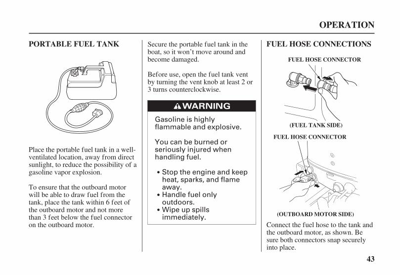
Gasoline is highlyflammable and explosive.
You can be burned orseriously injured whenhandling fuel.
Wipe up spillsimmediately.
Handle fuel onlyoutdoors.
Stop the engine and keepheat, sparks, and flameaway.
43
PORTABLE FUEL TANK FUEL HOSE CONNECTIONS
OPERATION
FUEL HOSE CONNECTOR
(OUTBOARD MOTOR SIDE)
FUEL HOSE CONNECTOR
(FUEL TANK SIDE)
Place the portable fuel tank in a well-ventilated location, away from directsunlight, to reduce the possibility of agasoline vapor explosion.
To ensure that the outboard motorwill be able to draw fuel from thetank, place the tank within 6 feet ofthe outboard motor and not morethan 3 feet below the fuel connectoron the outboard motor.
Secure the portable fuel tank in theboat, so it won’t move around andbecome damaged.
Before use, open the fuel tank ventby turning the vent knob at least 2 or3 turns counterclockwise.
Connect the fuel hose to the tank andthe outboard motor, as shown. Besure both connectors snap securelyinto place.
04/01/30 10:23:33 31ZY0600_044

44
FUEL PRIMING STARTING THE ENGINE
OPERATION
ENGINE STOPSWITCH
LANYARD
OUTLET END(MOTOR)
INLET END(TANK)
PRIMING BULB
SWITCH CLIP
H Type (tiller handle)
Check to be sure there are no fuelleaks before starting the engine.
Hold the priming bulb with the outletend higher than the inlet end.Squeeze the priming bulb severaltimes, until it feels firm, indicatingthat fuel has reached the carburetor.
Put the emergency stop switch clipin the engine stop switch, andattach the lanyard to your PFD(Personal Flotation Device) or toyour wrist, as shown.
The emergency stop switch clipand lanyard system is a safetydevice that will stop the engine ifyou fall away from the controlswhile operating the boat.
Always attach the lanyard to yourPFD, or to your wrist, beforestarting the engine.
The engine will not start or run,unless the switch clip is in theengine stop switch.
Do not squeeze the priming bulbwhen the engine is running becausethat could flood the carburetor.
1.
04/01/30 10:23:44 31ZY0600_045

45
OPERATION
CHOKE KNOB
START POSITIONN (neutral)
GEARSHIFT LEVER
CCLLOOSSEEDD
POINTER
THROTTLE GRIP
(manual choke type)Check the position of the gearshiftlever. It must be in the N (neutral)position for starting.
The engine will not start if thegearshift lever is in the F (forward)or R (reverse) position.
Do not turn the throttle grip beforestarting and align the STARTposition with the pointer forstarting the engine.
To start a cold engine, pull thechoke knob to the CLOSEDposition. To restart a warm engine,leave the choke knob in the OPENposition.
2.3.
4.
04/01/30 10:23:54 31ZY0600_046
46
OPERATION
ELECTRIC STARTERBUTTON
RECOILSTARTER GRIP
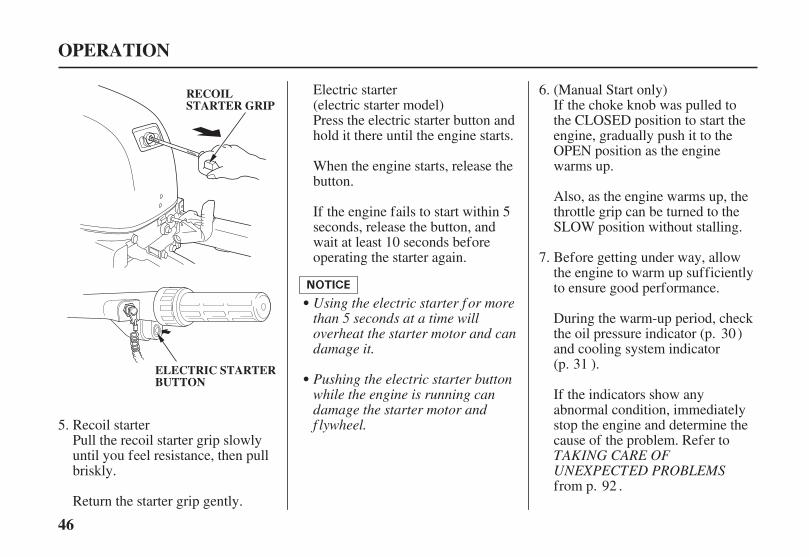
Using the electric starter f or morethan 5 seconds at a time willoverheat the starter motor and candamage it.
Pushing the electric starter buttonwhile the engine is running candamage the starter motor andf lywheel.
TAKING CARE OFUNEXPECTED PROBLEMS
Recoil starterPull the recoil starter grip slowlyuntil you feel resistance, then pullbriskly.
Return the starter grip gently.
Electric starter(electric starter model)Press the electric starter button andhold it there until the engine starts.
When the engine starts, release thebutton.
If the engine fails to start within 5seconds, release the button, andwait at least 10 seconds beforeoperating the starter again.
If the choke knob was pulled tothe CLOSED position to start theengine, gradually push it to theOPEN position as the enginewarms up.
Also, as the engine warms up, thethrottle grip can be turned to theSLOW position without stalling.
Before getting under way, allowthe engine to warm up sufficientlyto ensure good performance.
During the warm-up period, checkthe oil pressure indicator (p. )and cooling system indicator(p. ).
If the indicators show anyabnormal condition, immediatelystop the engine and determine thecause of the problem. Refer to
from p. .
5.
6.
7.
(Manual Start only)
30
31
92
04/01/30 10:24:05 31ZY0600_047
47
R Type(remote control)
OPERATION
SWITCH CLIP LANYARD
N (neutral)
CONTROLLEVER
Side-Mount Type
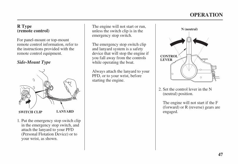
For panel-mount or top-mountremote control information, refer tothe instructions provided with theremote control equipment.
Put the emergency stop switch clipin the emergency stop switch, andattach the lanyard to your PFD(Personal Flotation Device) or toyour wrist, as shown.
Set the control lever in the N(neutral) position.
The engine will not start if the F(forward) or R (reverse) gears areengaged.
The emergency stop switch clipand lanyard system is a safetydevice that will stop the engine ifyou fall away from the controlswhile operating the boat.
Always attach the lanyard to yourPFD, or to your wrist, beforestarting the engine.
The engine will not start or run,unless the switch clip is in theemergency stop switch.
1.
2.
04/01/30 10:24:17 31ZY0600_048

48
OPERATION
IGNITION SWITCH KEY
ONSTARTOFFFAST IDLE
FAST IDLE LEVER
Using the electric starter f or morethan 5 seconds at a time willoverheat the starter motor and candamage it.
Turning the ignition switch key tothe START position while theengine is running can damage thestarter motor and f lywheel.
To start a cold engine, leave thefast idle lever in the OFF (fullylowered) position.
To restart a warm engine, raise thefast idle lever.
Fast idle lever cannot be raisedunless the control lever is in the N(neutral) position.
The control lever cannot be movedaway from the N (neutral) positionunless the fast idle lever is lowered.
Turn the ignition switch key to theSTART position and hold it thereuntil the engine starts.
When the engine starts, release thekey, allowing it to return to the ONposition.
If the engine fails to start within 5seconds, release the key and waitat least 10 seconds beforeoperating the starter again.
3. 4.
04/01/30 10:24:27 31ZY0600_049
49
EMERGENCY STARTING
OPERATION
UNLATCH
ENGINE COVER LATCH
FAST IDLE LEVER
TAKINGCARE OF UNEXPECTEDPROBLEMS
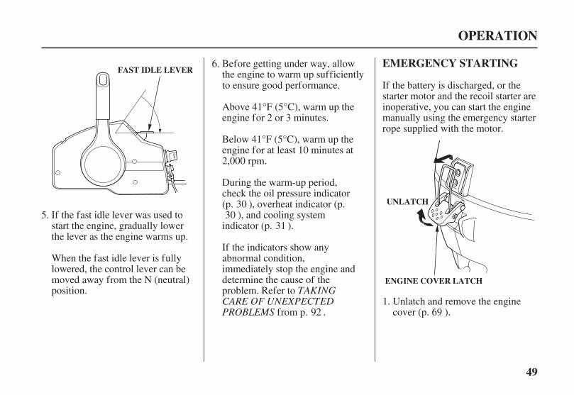
If the fast idle lever was used tostart the engine, gradually lowerthe lever as the engine warms up.
When the fast idle lever is fullylowered, the control lever can bemoved away from the N (neutral)position.
Before getting under way, allowthe engine to warm up sufficientlyto ensure good performance.
Above 41°F (5°C), warm up theengine for 2 or 3 minutes.
Below 41°F (5°C), warm up theengine for at least 10 minutes at2,000 rpm.
If the indicators show anyabnormal condition,immediately stop the engine anddetermine the cause of theproblem. Refer to
from p. .
During the warm-up period,check the oil pressure indicator(p. ), overheat indicator (p.
), and cooling systemindicator (p. ).
Unlatch and remove the enginecover (p. ).
If the battery is discharged, or thestarter motor and the recoil starter areinoperative, you can start the enginemanually using the emergency starterrope supplied with the motor.
1.
6.
5.30
31
6992
30
04/01/30 10:24:39 31ZY0600_050
-
50
OPERATION
RECOIL STARTERASSEMBLY FLYWHEEL (STARTER PULLEY)
KNOT
RECOIL STARTERASSEMBLY
NEUTRAL START CABLE
STARTER ROPE
FLANGE BOLT
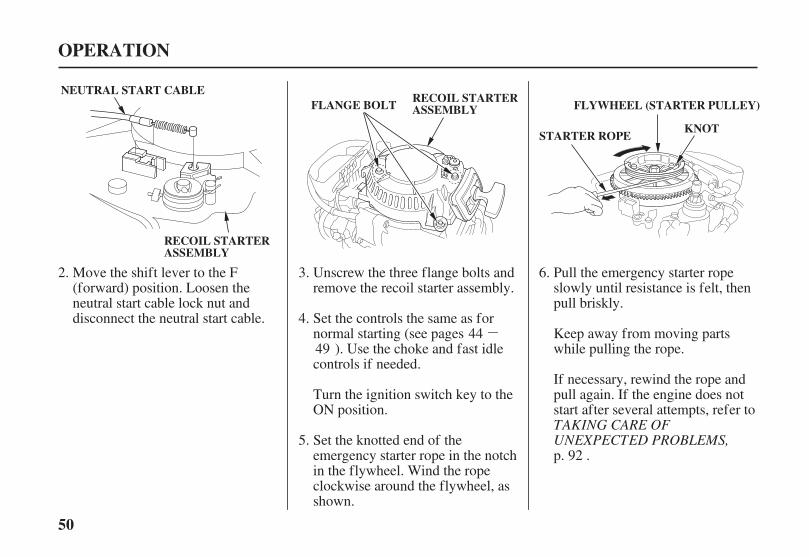
TAKING CARE OFUNEXPECTED PROBLEMS,Set the knotted end of the
emergency starter rope in the notchin the flywheel. Wind the ropeclockwise around the flywheel, asshown.
Set the controls the same as fornormal starting (see pages
). Use the choke and fast idlecontrols if needed.
Turn the ignition switch key to theON position.
Unscrew the three flange bolts andremove the recoil starter assembly.
Move the shift lever to the F(forward) position. Loosen theneutral start cable lock nut anddisconnect the neutral start cable.
Pull the emergency starter ropeslowly until resistance is felt, thenpull briskly.
Keep away from moving partswhile pulling the rope.
If necessary, rewind the rope andpull again. If the engine does notstart after several attempts, refer to
p. .
2. 3.
5.
4.
6.
4449
92
04/01/30 10:24:51 31ZY0600_051
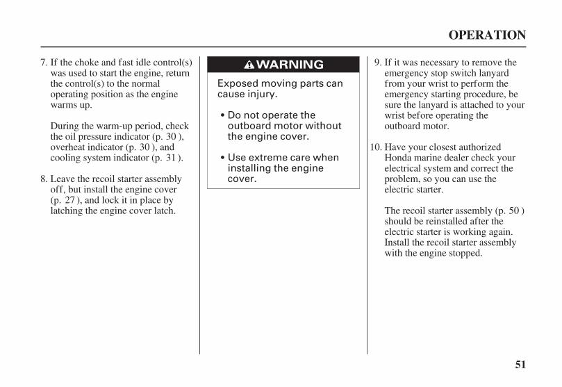
Exposed moving parts cancause injury.
Do not operate theoutboard motor withoutthe engine cover.
Use extreme care wheninstalling the enginecover.
51
OPERATION
If the choke and fast idle control(s)was used to start the engine, returnthe control(s) to the normaloperating position as the enginewarms up.
During the warm-up period, checkthe oil pressure indicator (p. ),overheat indicator (p. ), andcooling system indicator (p. ).
If it was necessary to remove theemergency stop switch lanyardfrom your wrist to perform theemergency starting procedure, besure the lanyard is attached to yourwrist before operating theoutboard motor.
Have your closest authorizedHonda marine dealer check yourelectrical system and correct theproblem, so you can use theelectric starter.
The recoil starter assembly (p. )should be reinstalled after theelectric starter is working again.Install the recoil starter assemblywith the engine stopped.
Leave the recoil starter assemblyoff, but install the engine cover(p. ), and lock it in place bylatching the engine cover latch.
7.
8.
30
31
27
9.
10.
50
30
04/01/30 10:25:00 31ZY0600_052
52
Normal Engine StoppingSTOPPING THE ENGINE
Emergency Engine Stopping
OPERATION
SWITCH CLIP
SWITCH CLIP
LANYARD
SLOW
THROTTLE GRIP
N (neutral)
LANYARD
PULL
PULL GEARSHIFT LEVER
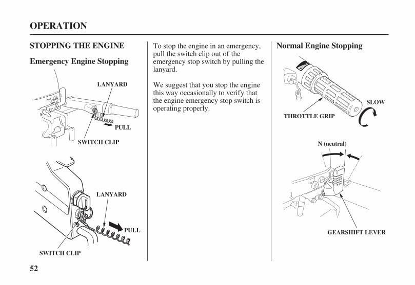
We suggest that you stop the enginethis way occasionally to verify thatthe engine emergency stop switch isoperating properly.
To stop the engine in an emergency,pull the switch clip out of theemergency stop switch by pulling thelanyard.
04/01/30 10:25:11 31ZY0600_053
53
OPERATION
N (neutral)
CONTROLLEVER ENGINE STOP SWITCH
IGNITION SWTCH KEY
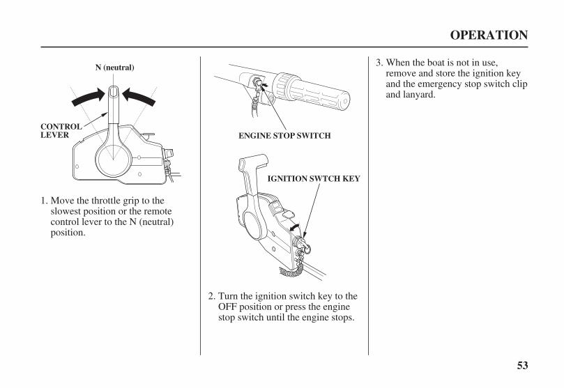
When the boat is not in use,remove and store the ignition keyand the emergency stop switch clipand lanyard.
Turn the ignition switch key to theOFF position or press the enginestop switch until the engine stops.
Move the throttle grip to theslowest position or the remotecontrol lever to the N (neutral)position.
1.
2.
3.
04/01/30 10:25:18 31ZY0600_054
54
H Type (tiller handle)
GEARSHIFT ANDTHROTTLE OPERATION
OPERATION
THROTTLE GRIP
THROTTLE GRIP
SLOW
THROTTLEFRICTIONADJUSTER
FIX
RREELLEEAASSEE
F (forward)
N (neutral)R (reverse)
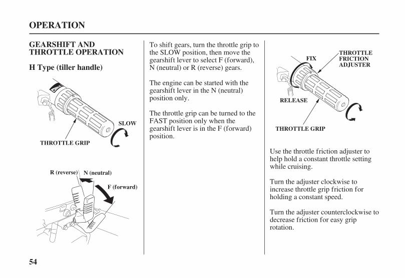
To shift gears, turn the throttle grip tothe SLOW position, then move thegearshift lever to select F (forward),N (neutral) or R (reverse) gears.
The engine can be started with thegearshift lever in the N (neutral)position only.
The throttle grip can be turned to theFAST position only when thegearshift lever is in the F (forward)position.
Use the throttle friction adjuster tohelp hold a constant throttle settingwhile cruising.
Turn the adjuster clockwise toincrease throttle grip friction forholding a constant speed.
Turn the adjuster counterclockwise todecrease friction for easy griprotation.
04/01/30 10:25:28 31ZY0600_055
55
(remote control)R Type
OPERATION
CONTROLLEVER
NEUTRALRELEASE LEVER
THROTTLEFRICTIONADJUSTER
TO INCREASEFRICTION
TO DECREASEFRICTION
Side-Mount Type
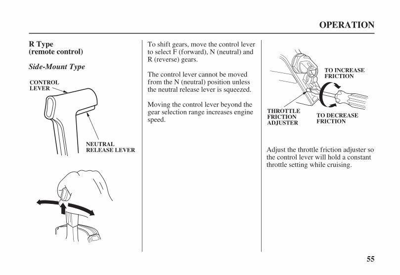
To shift gears, move the control leverto select F (forward), N (neutral) andR (reverse) gears.
The control lever cannot be movedfrom the N (neutral) position unlessthe neutral release lever is squeezed.
Moving the control lever beyond thegear selection range increases enginespeed.
Adjust the throttle friction adjuster sothe control lever will hold a constantthrottle setting while cruising.
04/01/30 10:25:39 31ZY0600_056
56
(remote control)R TypeSTEERING
H Type (tiller handle)
OPERATION
STEERING FRICTION LEVER
LLOOCCKKFFRREEEE
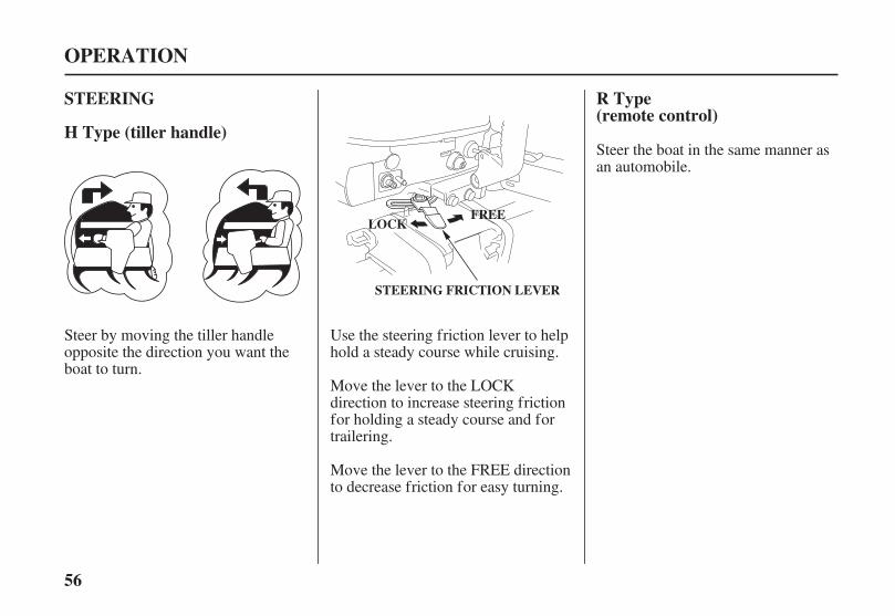
Steer by moving the tiller handleopposite the direction you want theboat to turn.
Use the steering friction lever to helphold a steady course while cruising.
Steer the boat in the same manner asan automobile.
Move the lever to the LOCKdirection to increase steering frictionfor holding a steady course and fortrailering.
Move the lever to the FREE directionto decrease friction for easy turning.
04/01/30 10:25:50 31ZY0600_057

57
CRUISING
Engine Speed
Transom Angle
OPERATION
MOTORADJUSTED TOOLOW
MOTORADJUSTED TOOHIGH
MOTORADJUSTEDCORRECTLY
ROUGHWAVES
Excessive transom angle duringoperation can cause propellerventilation, overheating, and waterpump damage.For best fuel economy, limit the
throttle opening to 80%. Use thethrottle friction control (p. orp. ) to help you hold a steadyspeed.
For rough water conditions or largewaves, slow down to prevent thepropeller from rising out of the water.
Under normal conditions, the boatwill perform best when theantiventilation plate is level with thewater.
Install the outboard motor at the besttransom angle for stable cruising andmaximum power.
Transom angle too large: Incorrectcauses boat to ‘‘squat’’.
Transom angle too small: Incorrectcauses boat to ‘‘bow steer’’.
It is necessary to adjust the transomangle of the outboard motor tocompensate for changes in boat load,weight distribution, water conditions,or propeller selection.
When cruising into a high wind,adjust the outboard motor downslightly to level the boat and improvestability. With a tail wind, adjust theoutboard motor up slightly (p. ).
5155
41
04/01/30 10:26:04 31ZY0600_058

58
OPERATION
BOW TOO HIGH DUE TO1.2.
BOW TOO LOW DUE TO1.2.
Motor Angle (Crusing)
O.K.
CORRECTGIVES MAXIMUM PERFORMANCE
LOAD IN THE FRONTMOTOR ADJUSTED TOO LOW
LOAD IN THE REARMOTOR ADJUSTED TOO HIGH
04/01/30 10:26:09 31ZY0600_059

59
SHALLOW WATEROPERATION
Manual tilt Type
OPERATION
45°
30°
ENGINECOVERGRIP
Do not use the tiller handle as alever to raise the outboard motor.Applying excessive f orce to the tillerhandle can damage it.
An excessive tilt angle duringoperation can cause propellerventilation, overheating, and waterpump damage.
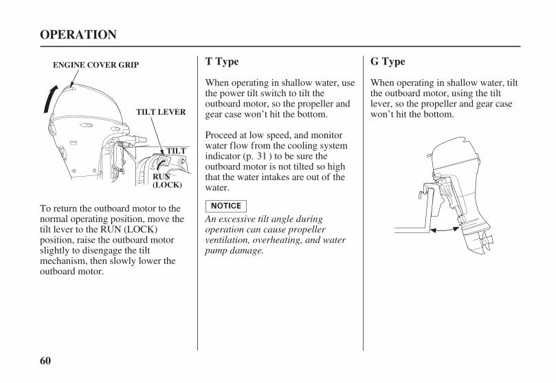
To tilt the outboard motor, move thetilt lever to the TILT position, thenraise the outboard motor to the 30° or45° position by pulling on the enginecover grip.
While the outboard motor is tilted,proceed at a low speed, and do notoperate the outboard motor in reverse.The outboard motor will risesuddenly if operated in reverse.
Monitor water flow from the coolingsystem indicator (p. ) to be surethe outboard motor is not tilted sohigh the water intake is out of thewater.
When operating in shallow water, tiltthe outboard motor, using the tiltlever, so the propeller and gear casewon’t hit the bottom.
31
04/01/30 10:26:19 31ZY0600_060
60
T Type G Type
OPERATION
ENGINE COVER GRIP
TILT LEVER
TTIILLTT
RRUUNN((LLOOCCKK))
An excessive tilt angle duringoperation can cause propellerventilation, overheating, and waterpump damage.
When operating in shallow water, tiltthe outboard motor, using the tiltlever, so the propeller and gear casewon’t hit the bottom.
Proceed at low speed, and monitorwater flow from the cooling systemindicator (p. ) to be sure theoutboard motor is not tilted so highthat the water intakes are out of thewater.
To return the outboard motor to thenormal operating position, move thetilt lever to the RUN (LOCK)position, raise the outboard motorslightly to disengage the tiltmechanism, then slowly lower theoutboard motor.
When operating in shallow water, usethe power tilt switch to tilt theoutboard motor, so the propeller andgear case won’t hit the bottom.
31
04/01/30 10:26:28 31ZY0600_061
61
OPERATION
ENGINE COVER GRIP
TILT LEVER
RRUUNN((LLOOCCKK))
TTIILLTT
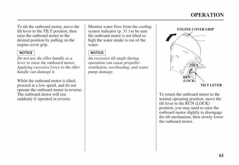
Do not use the tiller handle as alever to raise the outboard motor.Applying excessive f orce to the tillerhandle can damage it.
An excessive tilt angle duringoperation can cause propellerventilation, overheating, and waterpump damage.
While the outboard motor is tilted,proceed at a low speed, and do notoperate the outboard motor in reverse.The outboard motor will risesuddenly if operated in reverse.
Monitor water flow from the coolingsystem indicator (p. ) to be surethe outboard motor is not tilted sohigh the water intake is out of thewater.
To tilt the outboard motor, move thetilt lever to the TILT position, thenraise the outboard motor to thedesired position by pulling on theengine cover grip.
To return the outboard motor to thenormal operating position, move thetilt lever to the RUN (LOCK)position, you may need to raise theoutboard motor slightly to disengagethe tilt mechanism, then slowly lowerthe outboard motor.
31
04/01/30 10:26:36 31ZY0600_062
62
MOORING, BEACHING,LAUNCHING
G and T Types
Manual tilt Type
OPERATION
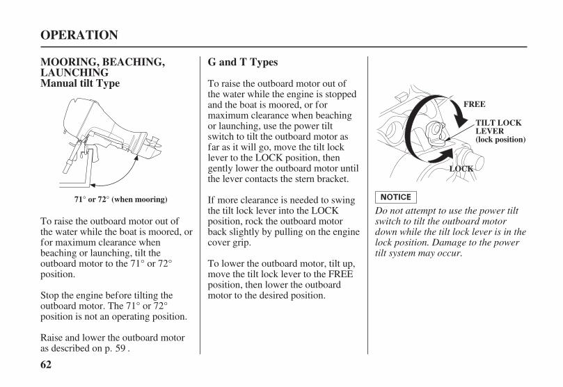
71° or 72° (when mooring)
FFRREEEE
LLOOCCKK
TILT LOCKLEVER(lock position)
Do not attempt to use the power tiltswitch to tilt the outboard motordown while the tilt lock lever is in thelock position. Damage to the powertilt system may occur.
To raise the outboard motor out ofthe water while the engine is stoppedand the boat is moored, or formaximum clearance when beachingor launching, use the power tiltswitch to tilt the outboard motor asfar as it will go, move the tilt locklever to the LOCK position, thengently lower the outboard motor untilthe lever contacts the stern bracket.
To raise the outboard motor out ofthe water while the boat is moored, orfor maximum clearance whenbeaching or launching, tilt theoutboard motor to the 71° or 72°position.
Stop the engine before tilting theoutboard motor. The 71° or 72°position is not an operating position.
Raise and lower the outboard motoras described on p. .
If more clearance is needed to swingthe tilt lock lever into the LOCKposition, rock the outboard motorback slightly by pulling on the enginecover grip.
To lower the outboard motor, tilt up,move the tilt lock lever to the FREEposition, then lower the outboardmotor to the desired position.
59
04/01/30 10:26:47 31ZY0600_063

※
※
63
T Type
OPERATION
MANUAL RELIEF VALVE
POWER(Valve closedto fix)
MANUAL(Valve opento release)
RIGHT STERN BRACKET
For manual tilting, use a flatscrewdriver to turn the valvecounterclockwise 2 and a half turns.Close the valve firmly afterpositioning the engine.
Be sure the valve is closed beforeoperating the outboard motor. If thevalve is not closed, the outboardmotor will tilt up when operated inreverse.
The outboard motor can also be tiltedmanually after opening the manualrelief valve. This feature enables theoutboard motor to be tilted when nobattery is connected.
Do not turn this screw. If thisscrew is turned hydraulic oilwill bleed out of the power tiltsystem. Should this happen itwill be necessary to contact yourclosest authorized HondaMarine dealer and have thesystem refilled.
:
04/01/30 10:26:55 31ZY0600_064
Improperly maintainingthis outboard motor, orfailure to correct a problembefore operation, can causea malfunction in which youcould be seriously hurt orkilled.
Always follow theinspection andmaintenancerecommendations andschedules in this owner’smanual.
64
THE IMPORTANCE OFMAINTENANCE
Maintenance, replacement, orrepair of the emission controldevices and systems may beperformed by any marine enginerepair establishment or individual,using parts that are ‘‘certified’’ toEPA standards.
SERVICING YOUR OUTBOARD MOTOR
Good maintenance is essential forsafe, economical, and trouble-freeoperation. It will also help reduce airpollution.
To help you properly care for youroutboard motor, the following pagesinclude a maintenance schedule,routine inspection procedures, andsimple maintenance procedures usingbasic hand tools. Other service tasksthat are more difficult, or requirespecial tools, are best handled byprofessionals and are normallyperformed by a Honda technician orother qualified mechanic.
Remember that your authorizedHonda marine dealer knows youroutboard motor best and is fullyequipped to maintain and repair it.
To ensure the best quality andreliability, use only new, genuineHonda parts or their equivalents forrepair and replacement.
The maintenance schedule applies tonormal operating conditions. If youoperate your outboard motor underunusual conditions, consult anauthorized Honda marine dealer forrecommendations applicable to yourindividual needs and use.
Honda will not deny a claim forwarranty coverage simply becauseyou did not maintain your outboard.However, any part that fails due tolack of maintenance, or impropermaintenance will not be coveredunder your product warranty.
04/01/30 10:27:05 31ZY0600_065
-
-
-
Failure to properly followmaintenance instructionsand precautions can causeyou to be seriously hurt orkilled.
Always follow theprocedures andprecautions in the owner’smanual.
65
MAINTENANCE SAFETY Safety Precautions
Burns from hot parts.
Injury from moving parts.
Carbon monoxide poisoningfrom engine exhaust.
SERVICING YOUR OUTBOARD MOTOR
Some of the most important safetyprecautions follow. However, wecannot warn you of everyconceivable hazard that can arise inperforming maintenance. Only youcan decide whether or not you shouldperform a given task.
Make sure the engine is off beforeyou begin any maintenance orrepairs. This will eliminate severalpotential hazards:
Read the instructions before youbegin, and make sure you have thetools and skills required.
To reduce the possibility of fire orexplosion, be careful whenworking around gasoline. Use onlya nonflammable solvent, notgasoline, to clean parts. Keepcigarettes, sparks, and flames awayfrom all fuel-related parts.
Wear gloves when handling thepropeller to protect your handsfrom sharp edges.Let the engine and exhaust
system cool before touching.
Do not run the engine unlessinstructed to do so.
Be sure there is adequateventilation whenever youoperate the engine.
04/01/30 10:27:17 31ZY0600_066
×
66
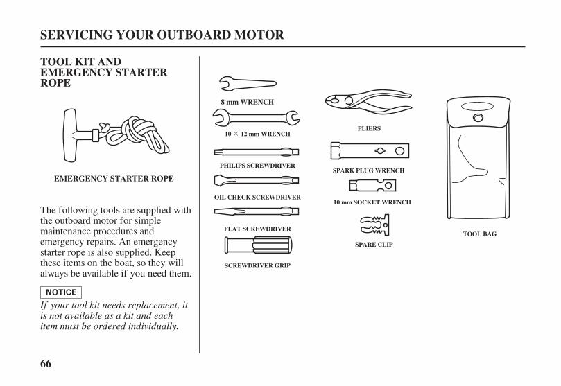
TOOL KIT ANDEMERGENCY STARTERROPE
SERVICING YOUR OUTBOARD MOTOR
EMERGENCY STARTER ROPE
8 mm WRENCH
10 12 mm WRENCH
PHILIPS SCREWDRIVER
OIL CHECK SCREWDRIVER
FLAT SCREWDRIVER
SCREWDRIVER GRIP
PLIERS
SPARK PLUG WRENCH
10 mm SOCKET WRENCH
SPARE CLIP
TOOL BAG
If your tool kit needs replacement, itis not available as a kit and eachitem must be ordered individually.
The following tools are supplied withthe outboard motor for simplemaintenance procedures andemergency repairs. An emergencystarter rope is also supplied. Keepthese items on the boat, so they willalways be available if you need them.
04/01/30 10:27:25 31ZY0600_067
○
○
○
○
○
○
○○
○○○
○
○○
○○○
○
○
67
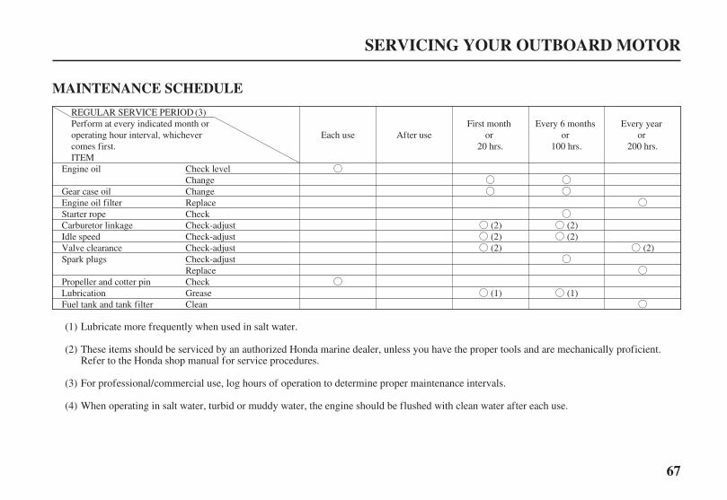
MAINTENANCE SCHEDULE
SERVICING YOUR OUTBOARD MOTOR
ITEM
REGULAR SERVICE PERIODPerform at every indicated month oroperating hour interval, whichevercomes first.
Check levelChangeChangeReplaceCheckCheck-adjustCheck-adjustCheck-adjustCheck-adjustReplaceCheckGreaseClean
Every yearor
200 hrs.
(2)
Each use After use
Engine oil
Gear case oilEngine oil filterStarter ropeCarburetor linkageIdle speedValve clearanceSpark plugs
Propeller and cotter pinLubricationFuel tank and tank filter
First monthor
20 hrs.
(2)(2)(2)
(1)
Every 6 monthsor
100 hrs.
(2)(2)
(1)
(3)
Lubricate more frequently when used in salt water.
These items should be serviced by an authorized Honda marine dealer, unless you have the proper tools and are mechanically proficient.Refer to the Honda shop manual for service procedures.
For professional/commercial use, log hours of operation to determine proper maintenance intervals.
When operating in salt water, turbid or muddy water, the engine should be flushed with clean water after each use.
(1)
(2)
(3)
(4)
04/01/30 10:27:38 31ZY0600_068

○
○
○
○
○
○
○
○○
○
68
SERVICING YOUR OUTBOARD MOTOR
ITEM
REGULAR SERVICE PERIODPerform at every indicated month oroperating hour interval, whichevercomes first.
After use
(4)
CheckReplaceCheckCheckReplaceCheck level-tightnessCheck-tightnessCheckCheckClean
Each useFirst month
or20 hrs.
(2)
Every 6 monthsor
100 hrs.
(2)
Every yearor
200 hrs.
(2)
(2)
Fuel filter
ThermostatFuel line
Bolts and NutsCrankcase breather tubeAnodeCooling water passages
(3)
Every 2 years ( Replace if necessary) (2)Battery and cable connection
Lubricate more frequently when used in salt water.
These items should be serviced by an authorized Honda marine dealer, unless you have the proper tools and are mechanically proficient.Refer to the Honda shop manual for service procedures.
For professional/commercial use, log hours of operation to determine proper maintenance intervals.
When operating in salt water, turbid or muddy water, the engine should be flushed with clean water after each use.
(1)
(2)
(3)
(4)
04/01/30 10:27:51 31ZY0600_069
※
※
69
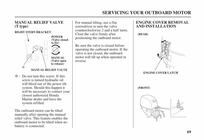
MANUAL RELIEF VALVE ENGINE COVER REMOVALAND INSTALLATION(T type)
SERVICING YOUR OUTBOARD MOTOR
(REAR)
(FRONT)
ENGINE COVER LATCHMANUAL RELIEF VALVE
PPOOWWEERR((VVaallvvee cclloosseeddttoo ffiixx))
MMAANNUUAALL((VVaallvvee ooppeennttoo rreelleeaassee))
RIGHT STERN BRACKET
Do not turn this screw. If thisscrew is turned hydraulic oilwill bleed out of the power tiltsystem. Should this happen itwill be necessary to contact yourclosest authorized HondaMarine dealer and have thesystem refilled.
The outboard motor can be tiltedmanually after opening the manualrelief valve. This feature enables theoutboard motor to be tilted when nobattery is connected.
For manual tilting, use a flatscrewdriver to turn the valvecounterclockwise 2 and a half turns.Close the valve firmly afterpositioning the outboard motor.
Be sure the valve is closed beforeoperating the outboard motor. If thevalve is not closed, the outboardmotor will tilt up when operated inreverse.
:
04/01/30 10:28:02 31ZY0600_070
70
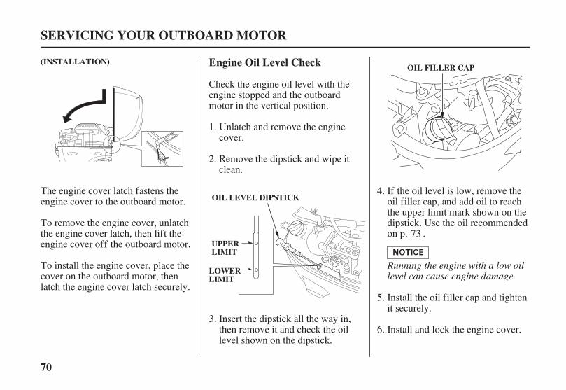
Engine Oil Level Check
SERVICING YOUR OUTBOARD MOTOR
UPPERLIMIT
LOWERLIMIT
OIL FILLER CAP
OIL LEVEL DIPSTICK
(INSTALLATION)
Running the engine with a low oillevel can cause engine damage.
Check the engine oil level with theengine stopped and the outboardmotor in the vertical position.
Unlatch and remove the enginecover.
Remove the dipstick and wipe itclean.
Insert the dipstick all the way in,then remove it and check the oillevel shown on the dipstick.
If the oil level is low, remove theoil filler cap, and add oil to reachthe upper limit mark shown on thedipstick. Use the oil recommendedon p. .
Install the oil filler cap and tightenit securely.
Install and lock the engine cover.
The engine cover latch fastens theengine cover to the outboard motor.
To remove the engine cover, unlatchthe engine cover latch, then lift theengine cover off the outboard motor.
To install the engine cover, place thecover on the outboard motor, thenlatch the engine cover latch securely.
1.
2.
3.
4.
5.
6.
73
04/01/30 10:28:17 31ZY0600_071
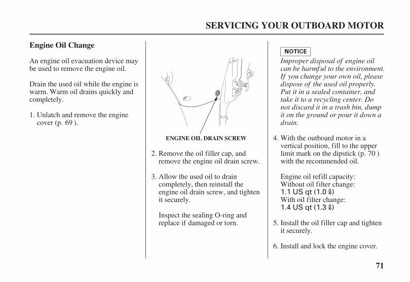
1.4 US qt (1.3 )
1.1 US qt (1.0 )
71
Engine Oil Change
SERVICING YOUR OUTBOARD MOTOR
ENGINE OIL DRAIN SCREW
Improper disposal of engine oilcan be harmf ul to the environment.If you change your own oil, pleasedispose of the used oil properly.Put it in a sealed container, andtake it to a recycling center. Donot discard it in a trash bin, dumpit on the ground or pour it down adrain.
Remove the oil filler cap, andremove the engine oil drain screw.
Allow the used oil to draincompletely, then reinstall theengine oil drain screw, and tightenit securely.
An engine oil evacuation device maybe used to remove the engine oil.
Drain the used oil while the engine iswarm. Warm oil drains quickly andcompletely.
Unlatch and remove the enginecover (p. ).
Inspect the sealing O-ring andreplace if damaged or torn.
Install and lock the engine cover.
Install the oil filler cap and tightenit securely.
With oil filter change:
Engine oil refill capacity:Without oil filter change:
With the outboard motor in avertical position, fill to the upperlimit mark on the dipstick (p. )with the recommended oil.
1.
2.
3.
4.
5.
6.
69
70
04/01/30 10:28:32 31ZY0600_072
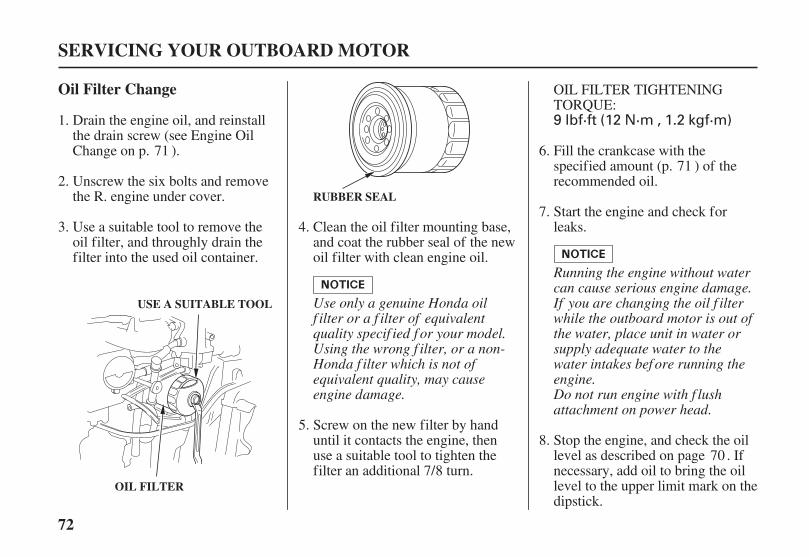
9 lbf·ft (12 N·m , 1.2 kgf·m)
72
Oil Filter Change
SERVICING YOUR OUTBOARD MOTOR
OIL FILTER
USE A SUITABLE TOOL
RUBBER SEAL
Use only a genuine Honda oilf ilter or a f ilter of equivalentquality specif ied f or your model.Using the wrong f ilter, or a non-Honda f ilter which is not ofequivalent quality, may causeengine damage.
Running the engine without watercan cause serious engine damage.If you are changing the oil f ilterwhile the outboard motor is out ofthe water, place unit in water orsupply adequate water to thewater intakes bef ore running theengine.Do not run engine with f lushattachment on power head.
Drain the engine oil, and reinstallthe drain screw (see Engine OilChange on p. ).
Unscrew the six bolts and removethe R. engine under cover.
Use a suitable tool to remove theoil filter, and throughly drain thefilter into the used oil container.
Screw on the new filter by handuntil it contacts the engine, thenuse a suitable tool to tighten thefilter an additional 7/8 turn.
OIL FILTER TIGHTENINGTORQUE:
Fill the crankcase with thespecified amount (p. ) of therecommended oil.
Start the engine and check forleaks.Clean the oil filter mounting base,
and coat the rubber seal of the newoil filter with clean engine oil.
Stop the engine, and check the oillevel as described on page . Ifnecessary, add oil to bring the oillevel to the upper limit mark on thedipstick.
1.
2.
3. 4.
5.
6.
7.
8.
71
70
71
04/01/30 10:28:47 31ZY0600_073
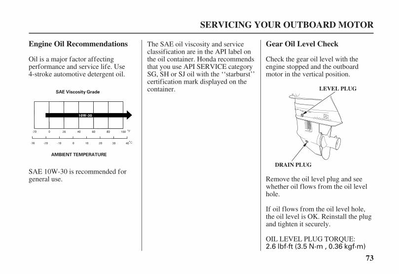
AMBIENT TEMPERATURE
SAE Viscosity Grade
2.6 lbf·ft (3.5 N·m , 0.36 kgf·m)
73
Engine Oil Recommendations Gear Oil Level Check
SERVICING YOUR OUTBOARD MOTOR
LEVEL PLUG
DRAIN PLUG
Oil is a major factor affectingperformance and service life. Use4-stroke automotive detergent oil.
Check the gear oil level with theengine stopped and the outboardmotor in the vertical position.
Remove the oil level plug and seewhether oil flows from the oil levelhole.
If oil flows from the oil level hole,the oil level is OK. Reinstall the plugand tighten it securely.
OIL LEVEL PLUG TORQUE:
The SAE oil viscosity and serviceclassification are in the API label onthe oil container. Honda recommendsthat you use API SERVICE categorySG, SH or SJ oil with the ‘‘starburst’’certification mark displayed on thecontainer.
SAE 10W-30 is recommended forgeneral use.
04/01/30 10:28:59 31ZY0600_074

74
Gear Oil Change
SERVICING YOUR OUTBOARD MOTOR
If no oil flows from the oil level hole,add the recommended oil followingthe procedure described in Gear OilChange.
Change the gear oil with the enginestopped and the outboard motor inthe vertical position.
Remove any metal particles fromthe magnetic end of the oil drainplug.
Place a suitable container belowthe oil drain hole to catch the usedoil, then remove the oil level plugand oil drain plug.
Allow the used oil to draincompletely, then install an oilpump adapter in the oil drain hole.
If water or contaminated (milky-colored) oil flows out the drainhole when the plug is removed,have the outboard motor checkedby an authorized Honda Marinedealer.
1.
2.
3.
04/01/30 10:29:08 31ZY0600_075
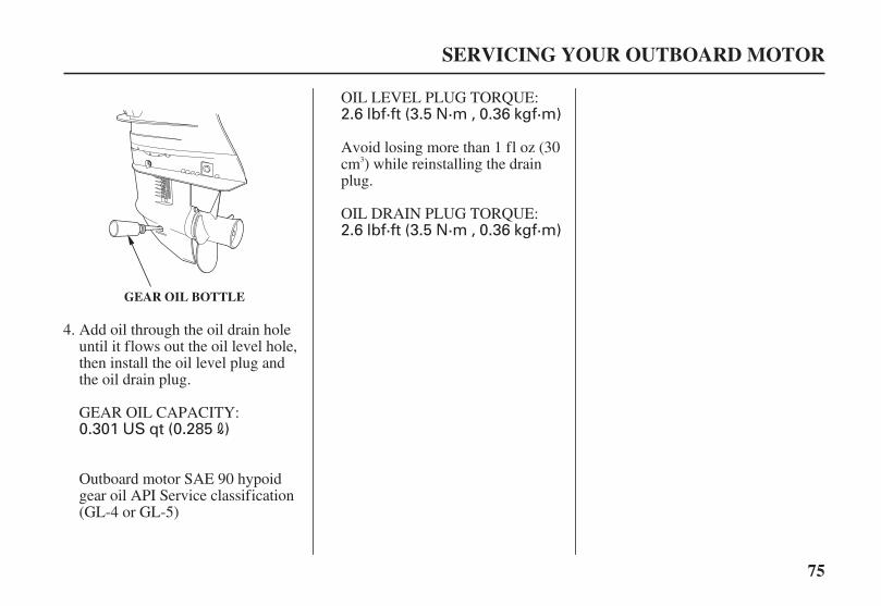
0.301 US qt (0.285 )
2.6 lbf·ft (3.5 N·m , 0.36 kgf·m)
2.6 lbf·ft (3.5 N·m , 0.36 kgf·m)
75
SERVICING YOUR OUTBOARD MOTOR
GEAR OIL BOTTLE
Add oil through the oil drain holeuntil it flows out the oil level hole,then install the oil level plug andthe oil drain plug.
GEAR OIL CAPACITY:
OIL LEVEL PLUG TORQUE:
Avoid losing more than 1 fl oz (30cm ) while reinstalling the drainplug.
OIL DRAIN PLUG TORQUE:
Outboard motor SAE 90 hypoidgear oil API Service classification(GL-4 or GL-5)
4.
3
04/01/30 10:29:17 31ZY0600_076

76
Lubrication Points
SERVICING YOUR OUTBOARD MOTOR
PROPELLER SHAFT
TILLER HANDLE THROTTLE REEL
CLAMP SCREWSSWIVEL CASE
MOUNT FRAME
ADJUSTING ROD/TILT STOPPER
TILT SHAFT
To prevent corrosion, apply anticorrosion oil to pivotsurf aces where grease cannot penetrate.
Apply marine ‘‘waterproof grease’’ is industry term tothe following parts:Lubrication interval:20 operating hours or a month after the date of purchasefor initial, then every 100 operating hours or 6 months.
Apply Honda Marine Corrosion Inhibitor (or equivalent) to all areas under the engine cover and any exposed metalsurfaces except the belts.
04/01/30 10:29:27 31ZY0600_077
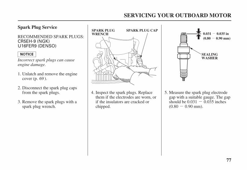
--
--
U16FER9 (DENSO)CR5EH-9 (NGK)
77
Spark Plug Service
SERVICING YOUR OUTBOARD MOTOR
SPARK PLUGWRENCH
SPARK PLUG CAP0.031 0.035 in(0.80 0.90 mm)
SEALINGWASHERIncorrect spark plugs can cause
engine damage.
RECOMMENDED SPARK PLUGS:
Unlatch and remove the enginecover (p. ).
Disconnect the spark plug capsfrom the spark plugs. Measure the spark plug electrode
gap with a suitable gauge. The gapshould be 0.031 0.035 inches(0.80 0.90 mm).
Remove the spark plugs with aspark plug wrench.
Inspect the spark plugs. Replacethem if the electrodes are worn, orif the insulators are cracked orchipped.
1.
2.
3.
4. 5.
69
04/01/30 10:29:36 31ZY0600_078
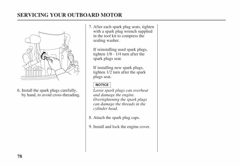
78
SERVICING YOUR OUTBOARD MOTOR
Loose spark plugs can overheatand damage the engine.Overtightening the spark plugscan damage the threads in thecylinder head.
Install the spark plugs carefully,by hand, to avoid cross-threading.
After each spark plug seats, tightenwith a spark plug wrench suppliedin the tool kit to compress thesealing washer.
If reinstalling used spark plugs,tighten 1/8 - 1/4 turn after thespark plugs seat.
If installing new spark plugs,tighten 1/2 turn after the sparkplugs seat.
Attach the spark plug caps.
Install and lock the engine cover.
6.
7.
8.
9.
04/01/30 10:29:45 31ZY0600_079

3.2 US gal (12 )
Gasoline is highlyflammable and explosive.
You can be burned orseriously injured whenhandling fuel.
Stop the engine and keepheat, sparks, and flameaway.Handle fuel onlyoutdoors.Wipe up spillsimmediately.
79
REFUELING
Portable Fuel Tank
SERVICING YOUR OUTBOARD MOTOR
VENT KNOBCLOSE
FUEL CAP
OPEN
FUEL GAUGE
SAFE FILL LEVEL
FUEL TANK CAPACITY:
Check the fuel gauge and refill thetank when necessary.
Remove the fuel tank from the boatfor refueling.
To refuel, turn the vent knobcounterclockwise to the OPENposition, and unscrew the fuel tankcap.
Refuel in a well-ventilated area. Fillthe tank to the SAFE FILL LEVELline.
After refueling, install the cap andtighten it securely. Turn the ventknob clockwise to the CLOSEDposition, and return the fuel tank tothe boat.
Never refill the fuel tank inside abuilding where gasoline fumesmay reach flames or sparks. Keepgasoline away from appliance pilotlights, barbecues, electricappliances, power tools, etc.
Spilled fuel is not only a fire hazard,it causes environmental damage.Wipe up spills immediately.
04/01/30 10:30:02 31ZY0600_080
Gasoline is highlyflammable and explosive.
You can be burned orseriously injured whenhandling fuel.
Stop the engine and keepheat, sparks, and flameaway.Handle fuel onlyoutdoors.Wipe up spillsimmediately.
80
FUEL RECOMMENDATIONS
Fuel Pump Filter Inspectionand Replacement
Use unleaded gasoline with a pumpoctane rating of 86 or higher.
SERVICING YOUR OUTBOARD MOTOR
Running the engine with persistentspark knock or pinging can causeengine damage.
Distributor’s LimitedWarranty
Your outboard motor is certified tooperate on unleaded gasoline.Unleaded gasoline produces fewerengine and spark plug deposits andextends exhaust system life.
Never use stale or contaminatedgasoline or an oil/gasoline mixture.Avoid getting dirt or water in the fueltank.
Occasionally you may hear a light‘‘spark knock’’ or ‘‘pinging’’(metallic rapping noise) whileoperating under heavy loads. This isno cause for concern.
If spark knock or pinging occurs at asteady engine speed, under normalload, change brands of gasoline. Ifspark knock or pinging persists, seean authorized Honda marine dealer.
Running the engine with persistentspark knock or pinging is misuse,and the
does not cover partsdamaged by misuse.
The fuel pump filter is located underthe engine cover, on the right side ofthe engine.
Water or sediment accumulated inthe filter can cause loss of power orhard starting. To prevent enginemalfunction, inspect the filter andreplace when necessary.
04/01/30 10:30:17 31ZY0600_081

81
SERVICING YOUR OUTBOARD MOTOR
ENGINE COVER LATCH
UNLATCH
FUEL PUMP FILTERFUEL HOSE
FUEL PUMP FILTER
Unlatch and remove the enginecover for access to the fuel pumpfilter.
Inspect the filter for water and/orsediment accumulation.
If the filter is OK, reinstall it. Ifwater and/or sediment are present,replace the filter as described inthe following steps. Alwaysreplace the filter at the scheduledreplacement interval (p. ).
Disconnect the fuel hose from theoutboard motor, and place clampson the fuel hoses on each side ofthe filter to prevent fuel leakagewhen the fuel hoses aredisconnected.
Remove the fuel hoses from theused filter, and discard the filter.
To ease hose removal, release thetube clamps by squeezing the clipends together with pliers whilepulling off the hoses.
3.
2.1.
4.
68
04/01/30 10:30:28 31ZY0600_082

82
Portable Fuel Tank and FilterCleaning
SERVICING YOUR OUTBOARD MOTOR
ARROW(Fuel Flow Direction)
TANK FILTER JOINT(Fuel Hose Connector)
O-RING
FILTER
Fuel Tank
Fuel Tank Filter
Install the new filter on the fuelhoses, with the fuel flow arrowpointing toward the fuel pump asshown. Fuel flow will be impededif the filter is installed backward.
Install and lock the engine cover.
Empty the portable fuel tank into anapproved gasoline container. Use afunnel to avoid spilling fuel. Rinsethe fuel tank with nonflammablesolvent to remove any accumulatedsediment.
Unscrew the fuel hose connectorby turning it counterclockwise,then remove the fuel hoseconnector and fuel filter from thetank.
Clean the filter in nonflammablesolvent. Inspect the fuel tank filterand the connector O-ring. Replacethem if damaged.
Reinstall the filter and hoseconnector in the fuel tank. Tightenthe hose connector securely.
Remove the fuel hose clamps, andconnect the fuel hose to theoutboard motor. Check for leaks.
5.
6.
7.
1.
2.
3.
04/01/30 10:30:42 31ZY0600_083

83
Recoil Starter Rope Inspection Anode Replacement
SERVICING YOUR OUTBOARD MOTOR
RECOIL STARTER ROPE
ANODES
ANODE(G and T types only)
Painting or coating the anodes willdef eat their purpose and will lead torust and corrosion damage to theoutboard motor. The anodes must beexposed to the water in order toprotect the outboard motor.
Always keep the emergency starterrope on the boat in case the recoilstarter rope fails.
Inspect the recoil starter rope, andreplace it if it becomes frayed.
Replace the anodes when they havebeen reduced to about half theiroriginal size, or if they are crumbling.
The anodes are located on each sideof the gearcase and the stern bracket(G and T types only). They are madeof a sacrificial material that helps toprotect the outboard motor fromcorrosion.
04/01/30 10:30:52 31ZY0600_084

84
Propeller Replacement
SERVICING YOUR OUTBOARD MOTOR
COTTER PIN
THRUST WASHERCOTTER PIN
PLAINWASHER
CASTLENUT
MARINE GREASE
PROPELLER
TOWARDGEAR CASE
Removal Installation
Install the thrust washer with thegrooved side toward the gear case.
Use a genuine Honda cotter pin.
Before replacing the propeller,remove the clip from the engine stopswitch to prevent any possibility ofthe engine being started while youare working with the propeller.
The propeller blades may have sharpedges, so wear heavy gloves toprotect your hands.
Remove the cotter pin, unscrew thecastle nut, remove the washer, thenremove the propeller and thrustwasher.
Operating the outboard motor athigher altitudes will reduce availablepower. This may require decreasingthe propeller pitch to maintain correctengine RPM.
Install the propeller in the reverseorder of removal.
04/01/30 10:31:04 31ZY0600_085

85
STORAGE PREPARATION
Cleaning and Flushing
STORAGE
GARDEN HOSEADAPTER
Cleaning
Flushing With the HondaGarden Hose Adapter (optionalequipment)
Proper storage preparation isessential for keeping your outboardmotor troublefree and looking good.The following steps will help to keeprust and corrosion from impairingyour outboard motor’s function andappearance, and will make the engineeasier to start when you use theoutboard motor again.
Thoroughly clean and flush theoutboard motor with fresh water afteroperation in dirty water or salt water.
After flushing, remove thegarden hose adapter, reinstallthe engine cover.
Touch up any damaged paint, andcoat areas that may rust with HondaCorrosion Inhibitor, or equivalent.Lubricate controls with a siliconespray lubricant.
Wash the outside of the outboardmotor with clean, fresh water to
remove mud, salt, seaweed, etc.
Disengage the emergency enginestop switch clip from the engine stopswitch, and pull the recoil starter ropeseveral times to expel any waterremaining in the water pump.
Unlatch the engine cover latch andremove the engine cover (p. ),and install the garden hose adapter.
Attach a garden hose from a freshwater faucet to the garden hoseadapter.
Turn on the fresh water supply,and verify that there is good waterpressure at the outboard motor.
Flush the engine with fresh waterfor at least 10 minutes.
Do not run the engine.
1.
2.
3.
4.
69
04/01/30 10:31:19 31ZY0600_086
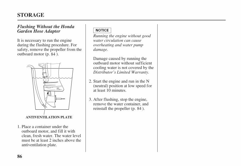
86
STORAGE
ANTIVENTILATION PLATE
Flushing Without the HondaGarden Hose Adapter
Running the engine without goodwater circulation can causeoverheating and water pumpdamage.
Distributor’s Limited Warranty.
It is necessary to run the engineduring the flushing procedure. Forsafety, remove the propeller from theoutboard motor (p. ).
Damage caused by running theoutboard motor without sufficientcooling water is not covered by the
Place a container under theoutboard motor, and fill it withclean, fresh water. The water levelmust be at least 2 inches above theantiventilation plate.
Start the engine and run in the N(neutral) position at low speed forat least 10 minutes.
After flushing, stop the engine,remove the water container, andreinstall the propeller (p. ).
1.
2.
3.
84
84
04/01/30 10:31:27 31ZY0600_087

87
Fuel
STORAGE
DRAIN SCREW
Adding a Fuel StabilizerDraining the Fuel System
Distributor’s Limited Warranty
Gasoline will oxidize and deterioratein storage. Old gasoline will causehard starting, and it leaves gumdeposits that clog the fuel system. Ifthe gasoline in your fuel tank andcarburetor deteriorates during storage,you may need to have the carburetorand other fuel system componentsserviced or replaced.
The length of time that gasoline canbe left in your fuel tank andcarburetor without causing functionalproblems will vary with such factorsas gasoline blend, your storagetemperatures, and whether the fueltank is partially or completely filled.The air in a partially filled fuel tankpromotes fuel deterioration. Verywarm storage temperatures acceleratefuel deterioration. Fuel deteriorationproblems may occur within a fewmonths, or even less if the gasolinewas not fresh when you filled thefuel tank.
Thedoes not cover fuel system damageor engine performance problemsresulting from neglected storagepreparation.
You can extend fuel storage life byadding a gasoline stabilizer that isformulated for that purpose, or youcan avoid fuel deterioration problemsby draining all the fuel from the fueltank and carburetor.
When adding a fuel stabilizer, fill thefuel tank with fresh gasoline. If onlypartially filled, air in the tank willpromote fuel deterioration duringstorage. If you keep an additionalcontainer of gasoline for refueling,be sure that it contains only freshgasoline.
Add fuel stabilizer following themanufacturer’s instructions.
After adding a fuel stabilizer, runthe engine in water for 10 minutesto be sure that the treated gasolinehas replaced the untreated gasolinein the carburetor.
Turn the engine OFF.
You can avoid fuel deteriorationproblems by draining the fuel tankand carburetors.
Disconnect the fuel hose from theoutboard motor.
1.
1.
2.
3.
04/01/30 10:31:42 31ZY0600_088
Wipe up spillsimmediately.
Handle fuel onlyoutdoors.
Stop the engine and keepheat, sparks, and flameaway.
You can be burned orseriously injured whenhandling fuel.
Gasoline is highlyflammable and explosive.
88
STORAGE
Drain the portable fuel tank into anapproved gasoline container, or ifyou need to store fuel in the fueltank, you can extend fuel storagelife by filling the fuel tank withfresh gasoline and adding a fuelstabilizer that is formulated forthat purpose. Firmly close the fuelcap vent knob.
After the fuel has drained from thecarburetor, tighten the drain screwsecurely.
With the outboard motor in avertical position, place anapproved gasoline container belowthe fuel drain outlet, and use afunnel to avoid spilling fuel.Loosen the drain screw to drainfuel from the carburetor.
Store portable fuel tank in a coolplace.
4.
3.2.
04/01/30 10:31:52 31ZY0600_089
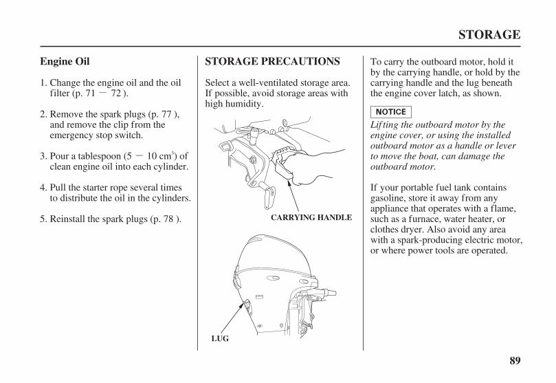
-
-
89
Engine Oil STORAGE PRECAUTIONS
STORAGE
CARRYING HANDLE
LUG
Lif ting the outboard motor by theengine cover, or using the installedoutboard motor as a handle or leverto move the boat, can damage theoutboard motor.
Change the engine oil and the oilfilter (p. ).
Pour a tablespoon (5 10 cm ) ofclean engine oil into each cylinder.
Pull the starter rope several timesto distribute the oil in the cylinders.
Reinstall the spark plugs (p. ).
Select a well-ventilated storage area.If possible, avoid storage areas withhigh humidity.
To carry the outboard motor, hold itby the carrying handle, or hold by thecarrying handle and the lug beneaththe engine cover latch, as shown.
If your portable fuel tank containsgasoline, store it away from anyappliance that operates with a flame,such as a furnace, water heater, orclothes dryer. Also avoid any areawith a spark-producing electric motor,or where power tools are operated.
Remove the spark plugs (p. ),and remove the clip from theemergency stop switch.
1.
2.
3.
4.
5.
71 72
77
78
3
04/01/30 10:32:06 31ZY0600_090
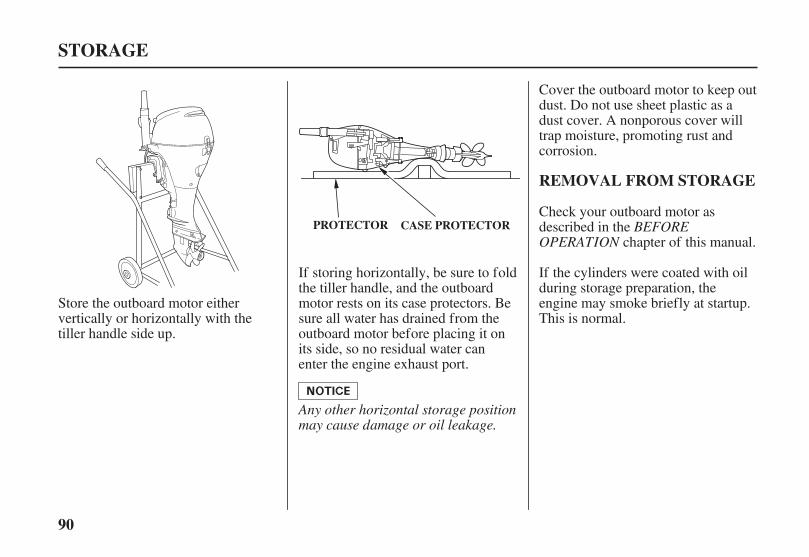
90
REMOVAL FROM STORAGE
STORAGE
PROTECTOR CASE PROTECTOR BEFOREOPERATION
Any other horizontal storage positionmay cause damage or oil leakage.
Cover the outboard motor to keep outdust. Do not use sheet plastic as adust cover. A nonporous cover willtrap moisture, promoting rust andcorrosion.
Check your outboard motor asdescribed in the
chapter of this manual.
If the cylinders were coated with oilduring storage preparation, theengine may smoke briefly at startup.This is normal.
If storing horizontally, be sure to foldthe tiller handle, and the outboardmotor rests on its case protectors. Besure all water has drained from theoutboard motor before placing it onits side, so no residual water canenter the engine exhaust port.
Store the outboard motor eithervertically or horizontally with thetiller handle side up.
04/01/30 10:32:15 31ZY0600_091
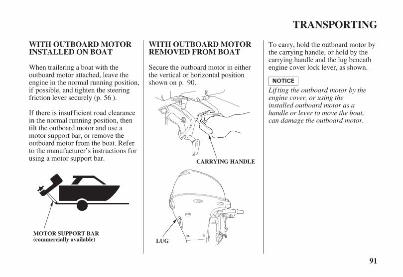
91
WITH OUTBOARD MOTORINSTALLED ON BOAT
WITH OUTBOARD MOTORREMOVED FROM BOAT
TRANSPORTING
CARRYING HANDLE
LUGMOTOR SUPPORT BAR(commercially available)
Lif ting the outboard motor by theengine cover, or using theinstalled outboard motor as ahandle or lever to move the boat,can damage the outboard motor.
When trailering a boat with theoutboard motor attached, leave theengine in the normal running position,if possible, and tighten the steeringfriction lever securely (p. ).
If there is insufficient road clearancein the normal running position, thentilt the outboard motor and use amotor support bar, or remove theoutboard motor from the boat. Referto the manufacturer’s instructions forusing a motor support bar.
Secure the outboard motor in eitherthe vertical or horizontal positionshown on p. .
To carry, hold the outboard motor bythe carrying handle, or hold by thecarrying handle and the lug beneathengine cover lock lever, as shown.
56
90
04/01/30 10:32:26 31ZY0600_092

92
TAKING CARE OF UNEXPECTED PROBLEMS
Recharge battery.Battery discharged.
Check battery.
Use emergency startingprocedure (p. ), then takeoutboard motor to an authorizedHonda Marine dealer, or refer tothe shop manual.
Battery connections loose orcorroded.
Starter malfunction, switchmalfunction, or electrical problemin the starting circuit.
Clean and tighten batteryconnections.
Replace or repair faultycomponents as necessary.
ELECTRIC STARTER WILLNOT OPERATE
Possible Cause Correction
Check fuse. Fuse burnt out. Replace fuse (p. ).
1.
2.
3.49
97
04/01/30 10:32:37 31ZY0600_093

93
TAKING CARE OF UNEXPECTED PROBLEMS
CorrectionPossible CauseENGINE WILL NOT START
Check emergency stop switchclip.
Clip not inserted in stop switch. Insert clip in stop switch.
Leave fast idle lever OFF, unlessengine is warm (p. ).
Fast idle lever raised (side-mounttype).
Throttle grip not in STARTposition (tiller-handle type).
Turn throttle grip to STARTposition (p. ).
Choke OPEN (tiller-handle andmanual choke type).
Gearshift lever or control lever notin neutral position.
Check control positions. Shift to neutral (p. or p. ).
Pull choke knob to CLOSEDposition, unless engine is warm(p. ).
1.
2. 20 25
19
45
48
04/01/30 10:32:51 31ZY0600_094
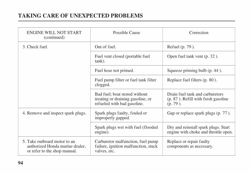
94
TAKING CARE OF UNEXPECTED PROBLEMS
CorrectionPossible CauseENGINE WILL NOT START(continued)
Check fuel. Out of fuel.
Fuel hose not primed.
Fuel pump filter or fuel tank filterclogged.
Bad fuel; boat stored withouttreating or draining gasoline, orrefueled with bad gasoline.
Spark plugs faulty, fouled orimproperly gapped.
Spark plugs wet with fuel (floodedengine).
Carburetor malfunction, fuel pumpfailure, ignition malfunction, stuckvalves, etc.
Refuel (p. ).
Squeeze priming bulb (p. ).
Replace fuel filters (p. ).
Replace or repair faultycomponents as necessary.
Fuel vent closed (portable fueltank).
Open fuel tank vent (p. ).
Take outboard motor to anauthorized Honda marine dealer,or refer to the shop manual.
Remove and inspect spark plugs.
Dry and reinstall spark plugs. Startengine with choke and throttle open.
Drain fuel tank and carburetors(p. ). Refill with fresh gasoline(p. ).
Gap or replace spark plugs (p. ).
3.
4.
5.
32
44
79
80
8779
77
04/01/30 10:33:10 31ZY0600_095
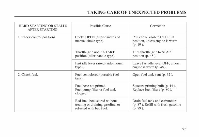
95
TAKING CARE OF UNEXPECTED PROBLEMS
CorrectionPossible CauseHARD STARTING OR STALLSAFTER STARTING
Check control positions.
Leave fast idle lever OFF, unlessengine is warm (p. ).
Throttle grip not in STARTposition (tiller-handle type).
Fast idle lever raised (side-mounttype).
Fuel vent closed (portable fueltank).
Fuel hose not primed.Fuel pump filter or fuel tankclogged.
Bad fuel; boat stored withouttreating or draining gasoline, orrefueled with bad fuel.
Open fuel tank vent (p. ).
Squeeze priming bulb (p. ).Replace fuel filters (p. ).
Check fuel.
Choke OPEN (tiller-handle andmanual choke type).
Turn throttle grip to STARTposition (p. ).
Drain fuel tank and carburetors(p. ). Refill with fresh gasoline(p. ).
Pull choke knob to CLOSEDposition, unless engine is warm(p. ).
1.
2.
19
45
48
32
4480
8779
04/01/30 10:33:26 31ZY0600_096
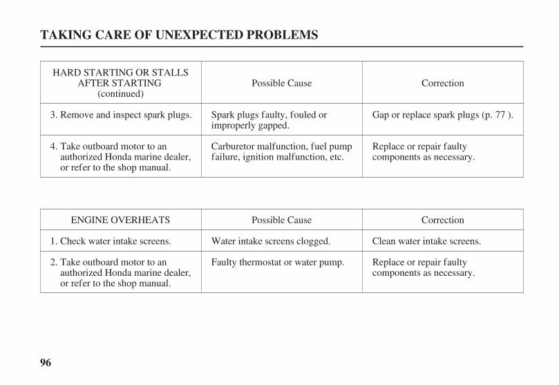
96
TAKING CARE OF UNEXPECTED PROBLEMS
HARD STARTING OR STALLSAFTER STARTING
(continued)
Take outboard motor to anauthorized Honda marine dealer,or refer to the shop manual.
Faulty thermostat or water pump. Replace or repair faultycomponents as necessary.
Check water intake screens. Water intake screens clogged. Clean water intake screens.
ENGINE OVERHEATS Possible Cause Correction
Carburetor malfunction, fuel pumpfailure, ignition malfunction, etc.
Replace or repair faultycomponents as necessary.
Take outboard motor to anauthorized Honda marine dealer,or refer to the shop manual.
Spark plugs faulty, fouled orimproperly gapped.
Remove and inspect spark plugs.
Possible Cause Correction
Gap or replace spark plugs (p. ).
2.
3.
4.
1.
77
04/01/30 10:33:43 31ZY0600_097

20A
97
BATTERY WILL NOTCHARGE AND ELECTRICSTARTER WILL NOTOPERATE
TAKING CARE OF UNEXPECTED PROBLEMS
FUSE CASE LID20A FUSE
BLOWN FUSE
SPARE 20A FUSE
Never use a f use with a ratinggreater than specif ied. Seriousdamage to the electrical systemcould result.
The battery-charging circuit and theelectric starter relay circuit areprotected by the 20-ampere fuse. Ifthe fuse burns out, the engine willnot charge the battery, and theelectric starter will not operate. Theengine can be started using the recoilstarter or the emergency starter rope.
Before further operation, try todetermine and correct the electricalproblem that caused the fuse toburn out. An uncorrected electricalproblem may cause the fuse toburn out again.
Reinstall the fuse case lid and theengine cover.
Fuse Replacement
With the engine stopped, removethe engine cover.
Remove the fuse case lid.
The ignition switch is also protectedby the 20-ampere fuse. If the fuseburns out, the engine will not start orrun, and the power tilt switch will notoperate.
Remove and inspect the fuse. Ifburnt out, install a replacementfuse of the specified rating. Theoutboard motor only comes withone spare fuse in the fuse holder.
DESIGNATED FUSE:
1.
2.
3.
4.
04/01/30 10:33:55 31ZY0600_098

98
OIL PRESSURE INDICATORLIGHT GOES OFF ANDENGINE SPEED IS LIMITED
TAKING CARE OF UNEXPECTED PROBLEMS
(tiller handle type)
(GREEN)
OIL PRESSURE(GREEN)
(remote control type)
If the throttle is closed suddenly afterfull throttle operation, engine speedmay drop below the specified idlerpm, and that could activate theengine protection systemmomentarily.
If low oil pressure activates theengine protection system, stop theengine, check the engine oil level(p. ), and add oil if needed.
With the engine oil at therecommended level, restart theengine. If the lubrication system isOK, the green indicator light shouldcome on within 30 seconds, and theengine will respond normally tothrottle grip or control leveroperation.
If the engine protection systemremains activated after 30 seconds,return to the nearest boat landing,and have the outboard motorinspected by an authorized Hondamarine dealer.
If oil pressure becomes low, thegreen indicator light will go off, andthe engine protection system willlimit engine speed. If you are atcruising speed, engine speed willdecrease automatically.
When normal oil pressure is restored,the engine speed will gradually riseto normal engine speed.
Remote-control types are equippedwith a buzzer that sounds when thegreen indicator light goes off.The buzzer sound stops below anengine speed of 1,400 rpm.
Low oil pressure may be the result ofa low engine oil level, or there maybe a problem with the enginelubrication system.
70
04/01/30 10:34:07 31ZY0600_099

99
OVERHEAT AND ENGINESPEED IS LIMITED
TAKING CARE OF UNEXPECTED PROBLEMS
(RED)
COOLING SYSTEM INDICATOR
(R type)
(H type)
(all types)
If the engine overheats, the redindicator light will come on and thebuzzer will sound a steady tone as theengine speed is reduced to 1,800 rpm.If the condition persists for another20 seconds, the engine will shut off.
Engine overheating may be the resultof restricted water intake screens, orthere may be a problem with thecooling system thermostat or waterpump.
If the engine is stopped after runningat full throttle, and then restartedsoon afterward, that could activatethe engine protection systemmomentarily.
If overheating activates the engineprotection system, idle the engine inneutral, and check the cooling systemindicator.
If the engine overheats, the enginespeed will be reduced to 1,800 rpm.If the condition persists for another20 seconds, the engine will shut off.
If you are at cruising speed when theoverheat protection system isactivated, the engine speed willdecrease automatically. When normalengine temperature is restored, theengine speed will gradually rise tonormal engine speed.
04/01/30 10:34:17 31ZY0600_100

100
TAKING CARE OF UNEXPECTED PROBLEMS
If water is flowing from the coolingsystem indicator, continue idling for30 seconds. If the cooling system isOK, the red indicator light should gooff within 30 seconds (R types), andthe engine will respond normally tothrottle grip or control leveroperation.
If there is still no water flowingfrom the cooling system indicator,or if the engine protection systemremains activated after 30 seconds,return to the nearest boat landing,and have the outboard motorinspected by an authorized Hondamarine dealer.
If there is no water flowing fromthe cooling system indicator, stopthe engine, and tilt the outboardmotor to inspect the water intakescreens. If restricted, clean thewater intake screens, return theoutboard motor to the runningposition, restart the engine, andcheck the cooling system indicatoragain.
04/01/30 10:34:21 31ZY0600_101
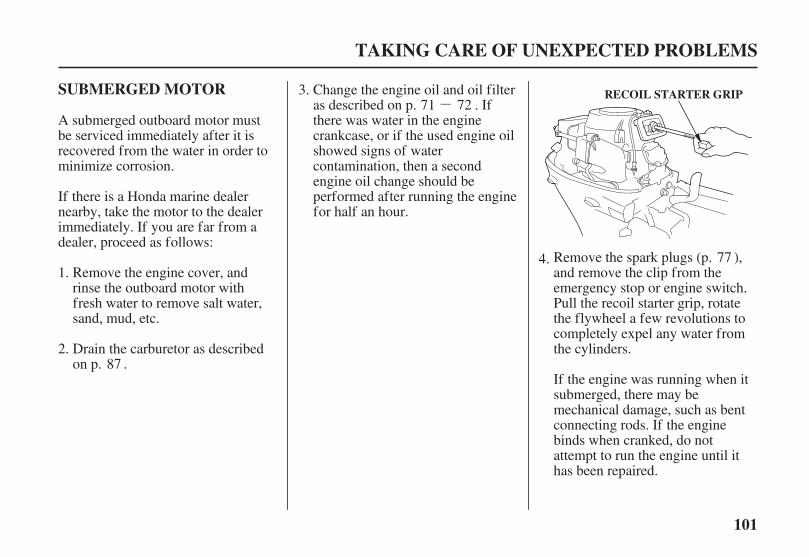
-
101
SUBMERGED MOTOR
TAKING CARE OF UNEXPECTED PROBLEMS
RECOIL STARTER GRIP
A submerged outboard motor mustbe serviced immediately after it isrecovered from the water in order tominimize corrosion.
If the engine was running when itsubmerged, there may bemechanical damage, such as bentconnecting rods. If the enginebinds when cranked, do notattempt to run the engine until ithas been repaired.
Change the engine oil and oil filteras described on p. . Ifthere was water in the enginecrankcase, or if the used engine oilshowed signs of watercontamination, then a secondengine oil change should beperformed after running the enginefor half an hour.
Remove the engine cover, andrinse the outboard motor withfresh water to remove salt water,sand, mud, etc.
Remove the spark plugs (p. ),and remove the clip from theemergency stop or engine switch.Pull the recoil starter grip, rotatethe flywheel a few revolutions tocompletely expel any water fromthe cylinders.Drain the carburetor as described
on p. .
If there is a Honda marine dealernearby, take the motor to the dealerimmediately. If you are far from adealer, proceed as follows:
1.
2.
3.
4.
87
71 72
77
04/01/30 10:34:30 31ZY0600_102
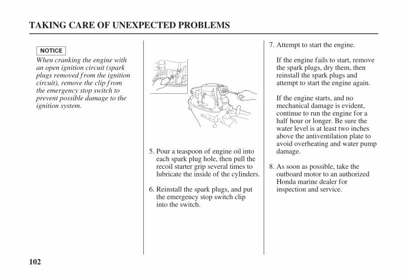
102
TAKING CARE OF UNEXPECTED PROBLEMS
When cranking the engine withan open ignition circuit (sparkplugs removed f rom the ignitioncircuit), remove the clip f romthe emergency stop switch toprevent possible damage to theignition system.
Attempt to start the engine.
Pour a teaspoon of engine oil intoeach spark plug hole, then pull therecoil starter grip several times tolubricate the inside of the cylinders.
Reinstall the spark plugs, and putthe emergency stop switch clipinto the switch.
If the engine fails to start, removethe spark plugs, dry them, thenreinstall the spark plugs andattempt to start the engine again.
If the engine starts, and nomechanical damage is evident,continue to run the engine for ahalf hour or longer. Be sure thewater level is at least two inchesabove the antiventilation plate toavoid overheating and water pumpdamage.
As soon as possible, take theoutboard motor to an authorizedHonda marine dealer forinspection and service.
5.
6.
7.
8.
04/01/30 10:34:39 31ZY0600_103

103
TECHNICAL INFORMATION
Serial Number Locations
TECHNICAL AND CONSUMER INFORMATION
SWIVEL CASE
PRODUCT IDENTIFICATIONNUMBER ENGINE SERIAL NUMBER
Record the product identificationnumber and engine serial number inthe space provided on this page. Youwill need these numbers whenordering parts, and when makingtechnical or warranty inquiries(p. ).
Product identification number: Engine serial number:
The engine serial number isstamped on the right front of theengine.
The product identification number isstamped on a plate attached on top ofthe swivel case.
118
04/01/30 10:34:48 31ZY0600_104
104
Carburetor Modification forHigh Altitude Operation
TECHNICAL AND CONSUMER INFORMATION
When the carburetors have beenmodif ied f or high altitude operation,the air-f uel mixture will be too leanf or low altitude use. Operation ataltitudes below 5,000 f eet (1,500meters) with modif ied carburetorsmay cause the engine to overheatand result in serious engine damage.For use at low altitudes, have anauthorized Honda Marine dealerreturn the carburetors to originalf actory specif ications.
At high altitude, the standardcarburetor air-fuel mixture will betoo rich. Performance will decrease,and fuel consumption will increase.A very rich mixture will also foul thespark plugs and cause hard starting.
High altitude performance can beimproved by specific modificationsto the carburetors. If you alwaysoperate your outboard motor ataltitudes above 5,000 feet (1,500meters), have an authorized Hondamarine dealer perform this carburetormodification.
Even with carburetor modification,engine horsepower will decreaseabout 3.5% for each 1,000-foot (300-meter) increase in altitude. The effectof altitude on horsepower will begreater than this if no carburetormodification is made.
04/01/30 10:34:55 31ZY0600_105

105
Oxygenated Fuels
ETHANOL:
MTBE:
METHANOL:
TECHNICAL AND CONSUMER INFORMATION
Some conventional gasolines arebeing blended with alcohol or anether compound. These gasolines arecollectively referred to as oxygenatedfuels. To meet clean air standards,some areas of the United States andCanada use oxygenated fuels to helpreduce emissions.
If you use an oxygenated fuel, besure it is unleaded and meets theminimum octane rating requirement.
Before using an oxygenated fuel, tryto confirm the fuel’s contents. Somestates/provinces require thisinformation to be posted on the pump.
The following are the EPA-approvedpercentages of oxygenates:
ethyl or grain alcohol;10% by volume.
You may use gasoline containing upto 10% ethanol by volume. Gasolinecontaining ethanol may be marketedunder the name ‘‘Gasohol’’.
Methyl Tertiary Butyl Ether;15% by volume.
You may use gasoline containing upto 15% MTBE by volume.
methyl or woodalcohol; 5% by volume.
You may use gasoline containing upto 5% methanol by volume, as longas it also contains cosolvents andcorrosion inhibitors to protect thefuel system. Gasoline containingmore than 5% methanol by volumemay cause starting and/orperformance problems. It may also
damage metal, rubber, and plasticparts of your fuel system.
If you notice any undesirableoperating symptoms, try anotherservice station, or switch to anotherbrand of gasoline.
Fuel system damage or performanceproblems resulting from the use of anoxygenated fuel containing morethan the percentages of oxygenatesmentioned above are not coveredunder warranty.
04/01/30 10:35:06 31ZY0600_106
106
Emission Control SystemInformation
TECHNICAL AND CONSUMER INFORMATION
Source of Emissions
Tampering and AlteringThe U.S. and Calif ornia CleanAir Acts
The combustion process producescarbon monoxide, oxides of nitrogen,and hydrocarbons. Control ofhydrocarbons and oxides of nitrogenis very important because, undercertain conditions, they react to formphotochemical smog when subjectedto sunlight. Carbon monoxide doesnot react in the same way, but it istoxic.
Honda utilizes lean carburetorsettings and other systems to reducethe emissions of carbon monoxide,oxides of nitrogen, and hydrocarbons.
Tampering with or altering theemission control system may increaseemissions beyond the legal limit.Among those acts that constitutetampering are:
Removal or alteration of any partof the intake, fuel, or exhaustsystems.
Alterations that would cause theengine to operate outside its designparameters.
The following instructions andprocedures must be followed in orderto keep the emissions from yourHonda engine within the emissionstandards.
EPA and California regulationsrequire all manufacturers to furnishwritten instructions describing theoperation and maintenance ofemission control systems.
04/01/30 10:35:17 31ZY0600_107

107
TECHNICAL AND CONSUMER INFORMATION
Maintenance
Replacement PartsProblems That May Af f ectEmissions
A manufacturer of an aftermarketpart assumes the responsibility thatthe part will not adversely affectemission performance. Themanufacturer or rebuilder of the partmust certify that use of the part willnot result in a failure of the engine tocomply with emission regulations.
Follow the maintenance schedule onp. . Remember that this scheduleis based on the assumption that yourmachine will be used for its designedpurpose. Sustained high-loadoperation, or use in unusualconditions, will require morefrequent service.
If you are aware of any of thefollowing symptoms, have yourengine inspected and repaired byyour servicing dealer.
Hard starting or stalling afterstarting.
Rough idle.
Misfiring or backfiring under load.
Afterburning (backfiring).
Black exhaust smoke or high fuelconsumption.
The emission control systems onyour Honda engine were designed,built, and certified to conform withEPA and California emissionregulations. We recommend the useof genuine Honda parts wheneveryou have maintenance done. Theseoriginal-design replacement parts aremanufactured to the same standardsas the original parts, so you can beconfident of their performance. Theuse of replacement parts that are notof the original design and qualitymay impair the effectiveness of youremission control system.
68
04/01/30 10:35:28 31ZY0600_108
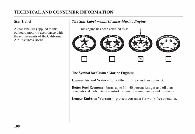
108
Star Label
The Symbol for Cleaner Marine Engines:
Cleaner Air and Water -
Better Fuel Economy -
Longer Emission Warranty -
TECHNICAL AND CONSUMER INFORMATION
The Star Label means Cleaner Marine Engine
A Star label was applied to thisoutboard motor in accordance withthe requirements of the CaliforniaAir Resources Board.
for healthier lifestyle and environment.
burns up to 30 - 40 percent less gas and oil thanconventional carbureted two-stroke engines, saving money and resources.
protects consumer for worry free operation.
This engine has been certified as a:
04/01/30 10:35:42 31ZY0600_109

109
Two StarsVery LowEmission
Three StarsUltra LowEmission
Four StarsSuper UltraLow Emission
One StarLowEmission
TECHNICAL AND CONSUMER INFORMATION
The one-star label identifies engines that meet the Air Resources Board’sPersonal Watercraft and Outboard marine engine 2001 exhaust emissionstandards. Engines meeting these standards have 75% lower emissions thanconventional carbureted two-stroke engines. These engines are equivalentto the U.S.EPA’s 2006 standards for marine engines.
The two-star label identifies engines that meet the Air Resources Board’sPersonal Watercraft and Outboard marine engine 2004 exhaust emissionstandards. Engines meeting these standards have 20% lower emissions thanOne Star-Low Emission engines.
The three-star label identifies engines that meet the Air Resources Board’sPersonal Watercraft and Outboard marine engine 2008 exhaust emissionstandards or the Sterndrive and inboard marine engine 2003-2008 exhaustemission standards. Engines meeting these standards have 65% loweremissions than One Star-Low Emission engines.
The four-star label identifies engines that meet the Air Resources Board’sSterndrive and Inboard marine engine 2009 exhaust emission standards.Personal Watercraft and Outboard marine engines may also comply withthese standards. Engines meeting these standards have 90% loweremissions than One Star-Low Emission engines.
Cleaner Watercraft - Get the Facts1-800-END-SMOG
www.arb.ca.gov
04/01/30 10:35:54 31ZY0600_110
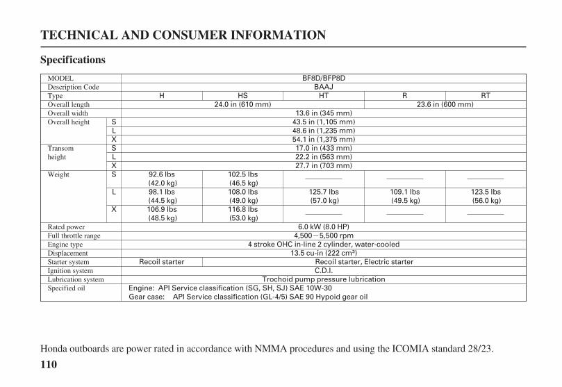
-
BF8D/BFP8D
API Service classification (GL-4/5) SAE 90 Hypoid gear oilAPI Service classification (SG, SH, SJ) SAE 10W-30
Trochoid pump pressure lubricationC.D.I.
Recoil starter Recoil starter, Electric starter13.5 cu-in (222 cm )
4 stroke OHC in-line 2 cylinder, water-cooled4,500 5,500 rpm
13.6 in (345 mm)43.5 in (1,105 mm)48.6 in (1,235 mm)54.1 in (1,375 mm)17.0 in (433 mm)22.2 in (563 mm)27.7 in (703 mm)
92.6 lbs(42.0 kg)98.1 lbs(44.5 kg)106.9 lbs(48.5 kg)
102.5 lbs(46.5 kg)108.0 lbs(49.0 kg)116.8 lbs(53.0 kg)
109.1 lbs(49.5 kg)
HSH R24.0 in (610 mm) 23.6 in (600 mm)
HTBAAJ
RT
125.7 lbs(57.0 kg)
123.5 lbs(56.0 kg)
6.0 kW (8.0 HP)
Engine:Gear case:
SLXSLXS
L
X
110
Specifications
TECHNICAL AND CONSUMER INFORMATION
Honda outboards are power rated in accordance with NMMA procedures and using the ICOMIA standard 28/23.
Weight
Transomheight
Overall heightOverall widthOverall lengthTypeDescription CodeMODEL
Specified oilLubrication systemIgnition systemStarter systemDisplacementEngine typeFull throttle rangeRated power
04/01/30 10:36:19 31ZY0600_111

- - -
- -±±±
1.4 US qt (1.3 )0.301 US qt (0.285 )
ULTRA · LOW EMISSION12V 6A
Water cooling with thermostat
CR5EH-9 (NGK)Diaphragm type fuel pump
Automotive unleaded gasoline(91 research octane, 86 pump octane, or higher)
3.2 US gal (12 )Forward-Neutral-Reverse (dog type)
45° right and left
4 stages (8°, 12°, 16°, 20°)
68°Motor-mounted
Under water exhaust/thru hub
12V 12A 12V 12A
U16FER9 (DENSO)
5 stages (4°, 8°, 12°, 16°, 20°)
3 stages adjustment (30°, 45° and 71°)3 stages adjustment (30°, 45° and 72°)
Gear case:Engine:
No other adjustments needed.
(G and T types):
0.031 0.035 in (0.80 0.90 mm)900 50 rpm
IN: 0.17 0.02 mmEX: 0.23 0.02 mm
(G and T types):
,
(Manual tilt type):
(Manual tilt S and L handle type):(Manual tilt X handle type, and R type):
Refer to page 77.See shop manualSee shop manual
111
TECHNICAL AND CONSUMER INFORMATION
Tuneup
Oil capacity
Tilt angle
Transom angleSteering angleGear changeTank capacity
FuelFuel pumpSpark plugsExhaust systemCooling systemD.C. output
Remote controlsteering system
CARB star label
Spark plug gapIdle speedValve clearance(cold)Other specifications
Honda outboards are power rated in accordance with NMMA procedures and using the ICOMIA standard 28/23.
04/01/30 10:36:40 31ZY0600_112

-
BF9.9D/BFP9.9DBABJ
H
92.6 lbs(42.0 kg)98.1 lbs(44.5 kg)106.9 lbs(48.5 kg)
HS HT R RT
27.7 in (703 mm)
23.6 in (600 mm)24.0 in (610 mm)13.6 in (345 mm)
43.5 in (1,105 mm)48.6 in (1,235 mm)54.1 in (1,375 mm)17.0 in (433 mm)22.2 in (563 mm)
123.5 lbs(56.0 kg)129.0 lbs(58.5 kg)
109.1 lbs(49.5 kg)
125.7 lbs(57.0 kg)131.2 lbs(59.5 kg)
102.5 lbs(46.5 kg)108.0 lbs(49.0 kg)116.8 lbs(53.0 kg)
7.4 kW (9.9 HP)
Recoil starter13.5 cu-in (222 cm )
4 stroke OHC in-line 2 cylinder, water-cooled5,000 6,000 rpm
Recoil starter, Electric starterC.D.I.
Trochoid pump pressure lubricationAPI Service classification (SG, SH, SJ) SAE 10W-30
API Service classification (GL-4/5) SAE 90 Hypoid gear oil
SLXSLXS
L
X
Engine:Gear case:
112
Specifications
TECHNICAL AND CONSUMER INFORMATION
Honda outboards are power rated in accordance with NMMA procedures and using the ICOMIA standard 28/23.
DisplacementEngine typeFull throttle rangeRated power
Weight
Transomheight
Overall heightOverall widthOverall lengthTypeDescription CodeMODEL
Starter systemIgnition systemLubrication systemSpecified oil
04/01/30 10:37:06 31ZY0600_113

- - -
- -±±±
1.4 US qt (1.3 )0.301 US qt (0.285 )
ULTRA · LOW EMISSION12V 6A 12V 12A 12V 12A
Under water exhaust/thru hubWater cooling with thermostat
Diaphragm type fuel pumpAutomotive unleaded gasoline
(91 research octane, 86 pump octane, or higher)3.2 US gal (12 )
Forward-Neutral-Reverse (dog type)45° right and left
4 stages (8°, 12°, 16°, 20°)
68°Motor-mounted
CR5EH-9 (NGK) U16FER9 (DENSO)
5 stages (4°, 8°, 12°, 16°, 20°)
3 stages adjustment (30°, 45° and 71°)3 stages adjustment (30°, 45° and 72°)
Gear case:Engine:
No other adjustments needed.
(G and T types):
(G and T types):
0.031 0.035 in (0.80 0.90 mm)900 50 rpm
IN: 0.17 0.02 mmEX: 0.23 0.02 mm
,
(Manual tilt type):
(Manual tilt S and L handle type):(Manual tilt X handle type, and R type):
Refer to page 77.See shop manualSee shop manual
113
TECHNICAL AND CONSUMER INFORMATION
Tuneup
Oil capacity
Tilt angle
Transom angleSteering angleGear changeTank capacity
FuelFuel pumpSpark plugsExhaust systemCooling systemD.C. output
Remote controlsteering system
CARB star label
Spark plug gapIdle speedValve clearance(cold)Other specifications
Honda outboards are power rated in accordance with NMMA procedures and using the ICOMIA standard 28/23.
04/01/30 10:37:29 31ZY0600_114
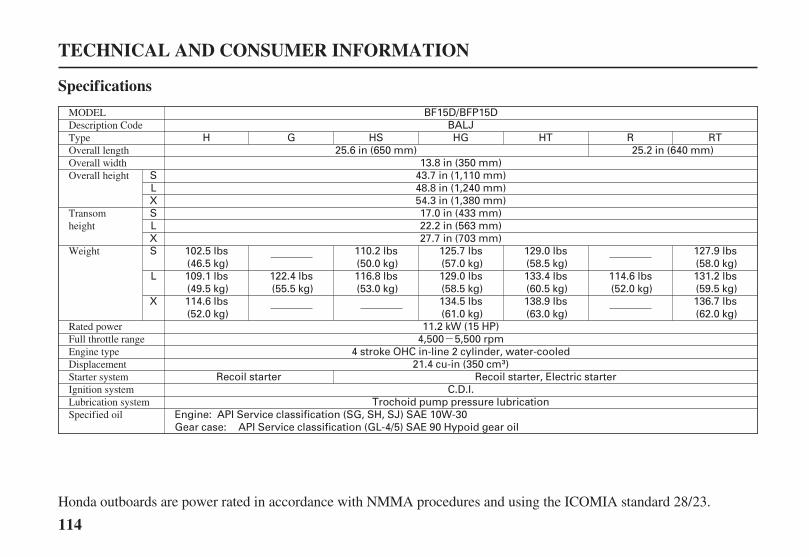
-
21.4 cu-in (350 cm )4 stroke OHC in-line 2 cylinder, water-cooled
4,500 5,500 rpm
102.5 lbs(46.5 kg)109.1 lbs(49.5 kg)
122.4 lbs(55.5 kg)
110.2 lbs(50.0 kg)116.8 lbs(53.0 kg)
125.7 lbs(57.0 kg)129.0 lbs(58.5 kg)134.5 lbs(61.0 kg)
H
27.7 in (703 mm)22.2 in (563 mm)17.0 in (433 mm)
54.3 in (1,380 mm)48.8 in (1,240 mm)43.7 in (1,110 mm)13.8 in (350 mm)
RBALJ
BF15D/BFP15D
131.2 lbs(59.5 kg)136.7 lbs(62.0 kg)
RTHTHGHSG25.2 in (640 mm)25.6 in (650 mm)
114.6 lbs(52.0 kg)
127.9 lbs(58.0 kg)
129.0 lbs(58.5 kg)133.4 lbs(60.5 kg)138.9 lbs(63.0 kg)
114.6 lbs(52.0 kg)
C.D.I.Trochoid pump pressure lubrication
API Service classification (SG, SH, SJ) SAE 10W-30API Service classification (GL-4/5) SAE 90 Hypoid gear oil
Recoil starter Recoil starter, Electric starter
11.2 kW (15 HP)
SLXSLXS
L
X
Engine:Gear case:
114
Specifications
TECHNICAL AND CONSUMER INFORMATION
Honda outboards are power rated in accordance with NMMA procedures and using the ICOMIA standard 28/23.
DisplacementEngine typeFull throttle rangeRated power
Weight
Transomheight
Overall heightOverall widthOverall lengthTypeDescription CodeMODEL
Starter systemIgnition systemLubrication systemSpecified oil
04/01/30 10:38:00 31ZY0600_115

- --
- -±±±
12V 12A 12V 12A12V 6A
1.4 US qt (1.3 )0.301 US qt (0.285 )
ULTRA · LOW EMISSION
Water cooling with thermostatUnder water exhaust/thru hub
Diaphragm type fuel pumpAutomotive unleaded gasoline
(91 research octane, 86 pump octane, or higher)3.2 US gal (12 )
Forward-Neutral-Reverse (dog type)45° right and left
4 stages (8°, 12°, 16°, 20°)
68°Motor-mounted
U16FER9 (DENSO)CR5EH-9 (NGK)
5 stages (4°, 8°, 12°, 16°, 20°)
3 stages adjustment (30°, 45° and 71°)3 stages adjustment (30°, 45° and 72°)
Gear case:Engine:
No other adjustments needed.
(G and T types):
(G and T types):
0.031 0.035 in (0.80 0.90 mm)900 50 rpm
IN: 0.17 0.02 mmEX: 0.23 0.02 mm
,
Refer to page 77.See shop manualSee shop manual
(Manual tilt type):
(Manual tilt S handle type):(Manual tilt L and X handle types, and R types):
115
TECHNICAL AND CONSUMER INFORMATION
Tuneup
Oil capacity
Tilt angle
Transom angleSteering angleGear changeTank capacity
FuelFuel pumpSpark plugsExhaust systemCooling systemD.C. output
Remote controlsteering system
CARB star label
Spark plug gapIdle speedValve clearance(cold)Other specifications
Honda outboards are power rated in accordance with NMMA procedures and using the ICOMIA standard 28/23.
04/01/30 10:38:21 31ZY0600_116

-
H G HS HG HT R RT25.6 in (650 mm) 25.2 in (640 mm)
13.8 in (350 mm)43.7 in (1,110 mm)48.8 in (1,240 mm)54.3 in (1,380 mm)17.0 in (433 mm)22.2 in (563 mm)27.7 in (703 mm)
102.5 lbs(46.5 kg)109.1 lbs(49.5 kg)
122.4 lbs(55.5 kg)
110.2 lbs(50.0 kg)116.8 lbs(53.0 kg)
125.7 lbs(57.0 kg)129.0 lbs(58.5 kg)134.5 lbs(61.0 kg)
129.0 lbs(58.5 kg)133.4 lbs(60.5 kg)138.9 lbs(63.0 kg)
111.3 lbs(50.5 kg)
127.9 lbs(58.0 kg)131.2 lbs(59.5 kg)136.7 lbs(62.0 kg)
14.9 kW (20 HP)
BAMJBF20D/BFP20D
5,000 6,000 rpm4 stroke OHC in-line 2 cylinder, water-cooled
21.4 cu-in (350 cm )
122.4 lbs(55.5 kg)
114.6 lbs(52.0 kg)
Recoil starter Recoil starter, Electric starterC.D.I.
Trochoid pump pressure lubricationAPI Service classification (SG, SH, SJ) SAE 10W-30
API Service classification (GL-4/5) SAE 90 Hypoid gear oil
SLXSLXS
L
X
Engine:Gear case:
116
Specifications
TECHNICAL AND CONSUMER INFORMATION
Honda outboards are power rated in accordance with NMMA procedures and using the ICOMIA standard 28/23.
DisplacementEngine typeFull throttle rangeRated power
Weight
Transomheight
Overall heightOverall widthOverall lengthTypeDescription CodeMODEL
Starter systemIgnition systemLubrication systemSpecified oil
04/01/30 10:38:52 31ZY0600_117
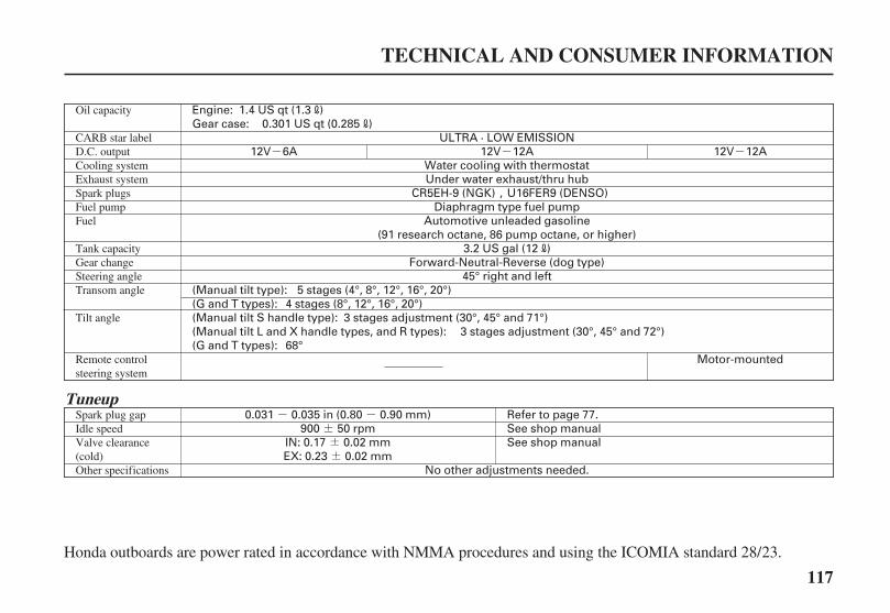
---
- -±±±
1.4 US qt (1.3 )0.301 US qt (0.285 )
ULTRA · LOW EMISSION12V 12A12V 12A12V 6A
Water cooling with thermostatUnder water exhaust/thru hub
Diaphragm type fuel pumpAutomotive unleaded gasoline
(91 research octane, 86 pump octane, or higher)3.2 US gal (12 )
Forward-Neutral-Reverse (dog type)45° right and left
4 stages (8°, 12°, 16°, 20°)
68°Motor-mounted
U16FER9 (DENSO)CR5EH-9 (NGK)
5 stages (4°, 8°, 12°, 16°, 20°)
3 stages adjustment (30°, 45° and 71°)3 stages adjustment (30°, 45° and 72°)
Gear case:Engine:
No other adjustments needed.
(G and T types):
(G and T types):
0.031 0.035 in (0.80 0.90 mm)900 50 rpm
IN: 0.17 0.02 mmEX: 0.23 0.02 mm
,
(Manual tilt type):
(Manual tilt S handle type):(Manual tilt L and X handle types, and R types):
Refer to page 77.See shop manualSee shop manual
117
TECHNICAL AND CONSUMER INFORMATION
Tuneup
Oil capacity
Tilt angle
Transom angleSteering angleGear changeTank capacity
FuelFuel pumpSpark plugsExhaust systemCooling systemD.C. output
Remote controlsteering system
CARB star label
Spark plug gapIdle speedValve clearance(cold)Other specifications
Honda outboards are power rated in accordance with NMMA procedures and using the ICOMIA standard 28/23.
04/01/30 10:39:12 31ZY0600_118

118
Warranty Service InformationCONSUMER INFORMATION
Honda Publications
American Honda Motor Co., Inc.
TECHNICAL AND CONSUMER INFORMATION
Shop Manual
Parts Catalog
Honda Marine dealership personnelare trained professionals. Theyshould be able to answer anyquestion you may have. If youencounter a problem that your dealerdoes not solve to your satisfaction,please discuss it with the dealership’smanagement. The Service Manageror General Manager can help. Almostall problems are solved in this way.
If you are dissatisfied with thedecision made by the dealership’smanagement, contact the HondaMarine Customer Relations Office.You can write:
Marine DivisionCustomer Relations Office4900 Marconi DriveAlpharetta, Georgia 30005-8847
Or telephone: (770) 497-6400
When you write or call, please giveus this information:
Model and serial numbers (p. )
Name of the dealer who sold theoutboard motor to you
Name and address of the dealerwho services your outboard motor
Date of purchase
Your name, address, and telephonenumber
A detailed description of theproblem
This manual covers completemaintenance and overhaul procedures.It is intended to be used by a skilledtechnician.
This manual provides complete,illustrated parts lists.
These publications will give youadditional information formaintaining and repairing youroutboard motor. You may purchasethem from your Honda marine dealer.
103
04/01/30 10:39:26 31ZY0600_119
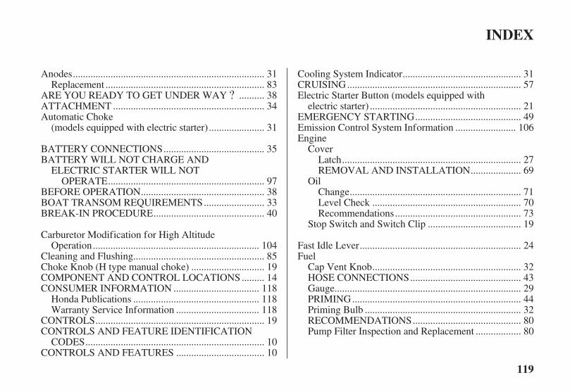
?
119
INDEX
...........................................................................Anodes . 31..............................................................Replacement . 83
.........ARE YOU READY TO GET UNDER WAY . 38...........................................................ATTACHMENT . 34
Automatic Choke.....................(models equipped with electric starter) . 31
.......................................BATTERY CONNECTIONS . 35BATTERY WILL NOT CHARGE AND
ELECTRIC STARTER WILL NOT.............................................................OPERATE . 97
................................................BEFORE OPERATION . 38.......................BOAT TRANSOM REQUIREMENTS . 33
...........................................BREAK-IN PROCEDURE . 40
Carburetor Modification for High Altitude.................................................................Operation . 104
...................................................Cleaning and Flushing . 85............................Choke Knob (H type manual choke) . 19
........COMPONENT AND CONTROL LOCATIONS . 14.................................CONSUMER INFORMATION . 118
.................................................Honda Publications . 118................................Warranty Service Information . 118
..................................................................CONTROLS . 19CONTROLS AND FEATURE IDENTIFICATION
......................................................................CODES . 10..................................CONTROLS AND FEATURES . 10
..............................................Cooling System Indicator . 31....................................................................CRUISING . 57
Electric Starter Button (models equipped with...........................................................electric starter) . 21
.........................................EMERGENCY STARTING . 49.......................Emission Control System Information . 106
EngineCover
......................................................................Latch . 27...................REMOVAL AND INSTALLATION . 69
Oil...................................................................Change . 71
..........................................................Level Check . 70.................................................Recommendations . 73
....................................Stop Switch and Switch Clip . 19
...............................................................Fast Idle Lever . 24Fuel
..........................................................Cap Vent Knob . 32...........................................HOSE CONNECTIONS . 43
.........................................................................Gauge . 29..................................................................PRIMING . 44
.............................................................Priming Bulb . 32..........................................RECOMMENDATIONS . 80
.................Pump Filter Inspection and Replacement . 80
04/01/30 10:39:30 31ZY0600_120
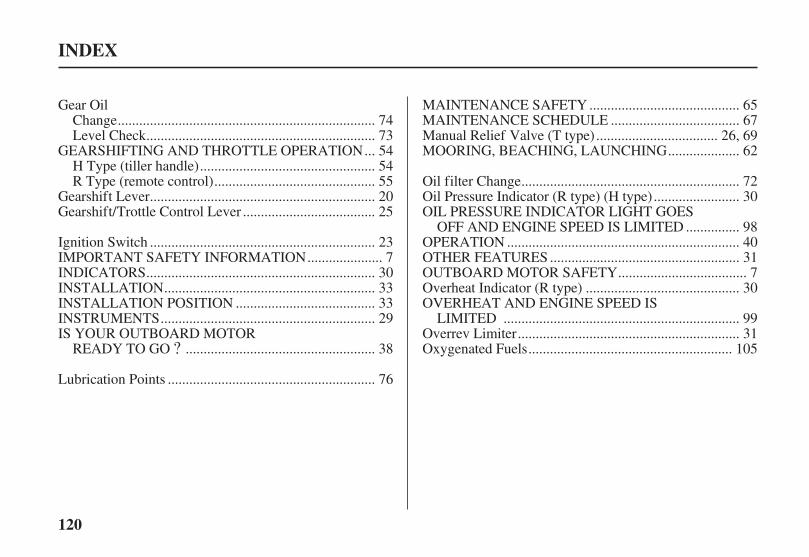
?
120
INDEX
Gear Oil.......................................................................Change . 74
...............................................................Level Check . 73..GEARSHIFTING AND THROTTLE OPERATION . 54
................................................H Type (tiller handle) . 54............................................R Type (remote control) . 55
..............................................................Gearshift Lever . 20....................................Gearshift/Trottle Control Lever . 25
..............................................................Ignition Switch . 23....................IMPORTANT SAFETY INFORMATION . 7
...............................................................INDICATORS . 30..........................................................INSTALLATION . 33
......................................INSTALLATION POSITION . 33...........................................................INSTRUMENTS . 29
IS YOUR OUTBOARD MOTOR....................................................READY TO GO . 38
.........................................................Lubrication Points . 76
.........................................MAINTENANCE SAFETY . 65...................................MAINTENANCE SCHEDULE . 67
.................................Manual Relief Valve (T type) . 26, 69...................MOORING, BEACHING, LAUNCHING . 62
............................................................Oil filter Change . 72.......................Oil Pressure Indicator (R type) (H type) . 30
OIL PRESSURE INDICATOR LIGHT GOES..............OFF AND ENGINE SPEED IS LIMITED . 98
................................................................OPERATION . 40....................................................OTHER FEATURES . 31
...................................OUTBOARD MOTOR SAFETY . 7..........................................Overheat Indicator (R type) . 30
OVERHEAT AND ENGINE SPEED IS.................................................................LIMITED . 99
.............................................................Overrev Limiter . 31........................................................Oxygenated Fuels . 105
04/01/30 10:39:34 31ZY0600_121
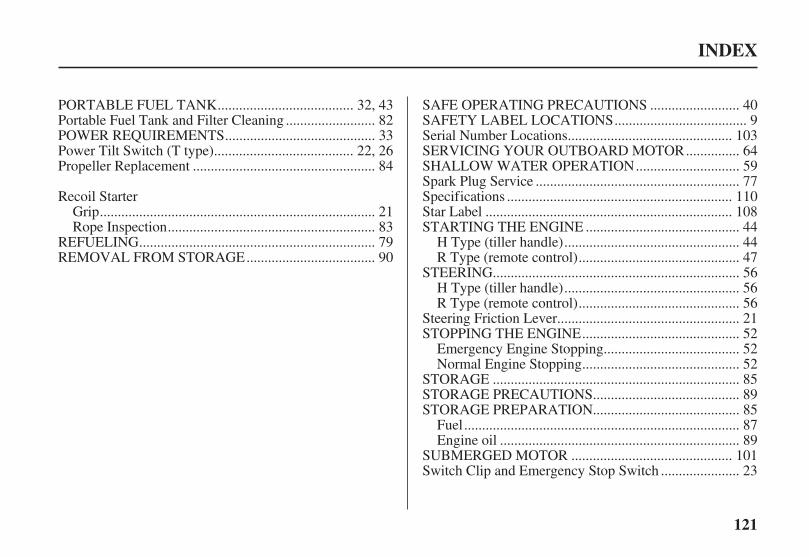
121
INDEX
.....................................PORTABLE FUEL TANK . 32, 43........................Portable Fuel Tank and Filter Cleaning . 82
.........................................POWER REQUIREMENTS . 33......................................Power Tilt Switch (T type) . 22, 26
..................................................Propeller Replacement . 84
Recoil Starter............................................................................Grip . 21
.........................................................Rope Inspection . 83.................................................................REFUELING . 79
...................................REMOVAL FROM STORAGE . 90
........................SAFE OPERATING PRECAUTIONS . 40....................................SAFETY LABEL LOCATIONS . 9
.............................................Serial Number Locations . 103..............SERVICING YOUR OUTBOARD MOTOR . 64
............................SHALLOW WATER OPERATION . 59........................................................Spark Plug Service . 77
..............................................................Specifications . 110....................................................................Star Label . 108
..........................................STARTING THE ENGINE . 44................................................H Type (tiller handle) . 44
............................................R Type (remote control) . 47....................................................................STEERING . 56
................................................H Type (tiller handle) . 56............................................R Type (remote control) . 56
..................................................Steering Friction Lever . 21...........................................STOPPING THE ENGINE . 52
.....................................Emergency Engine Stopping . 52...........................................Normal Engine Stopping . 52
....................................................................STORAGE . 85........................................STORAGE PRECAUTIONS . 89........................................STORAGE PREPARATION . 85
............................................................................Fuel . 87..................................................................Engine oil . 89
............................................SUBMERGED MOTOR . 101.....................Switch Clip and Emergency Stop Switch . 23
04/01/30 10:39:38 31ZY0600_122

122
INDEX
.................................Tachometer (optional equipment) . 28....TAKING CARE OF UNEXPECTED PROBLEMS . 92
TECHNICAL AND CONSUMER.....................................................INFORMATION . 103
.................................TECHNICAL INFORMATION . 103...............THE IMPORTANCE OF MAINTENANCE . 64
.............................................Throttle Friction Adjuster . 20..................................................................Throttle Grip . 20
Tilt.............................................Lever (manual tilt type) . 29
...........................................................Lever (G type) . 22......................................Lock Lever (G and T types) . 27
..TOOL KIT AND EMERGENCY STARTER ROPE . 66.....................................Transom Angle Adjusting Rod . 27
...................TRANSOM ANGLE ADJUSTMENT . 35, 41........................................................TRANSPORTING . 91
WITH OUTBOARD MOTOR INSTALLED.............................................................ON BOAT . 91
WITH OUTBOARD MOTOR REMOVED.......................................................FROM BOAT . 91
.........................WIRING DIAGRAMS . Inside back cover
04/01/30 10:39:41 31ZY0600_123
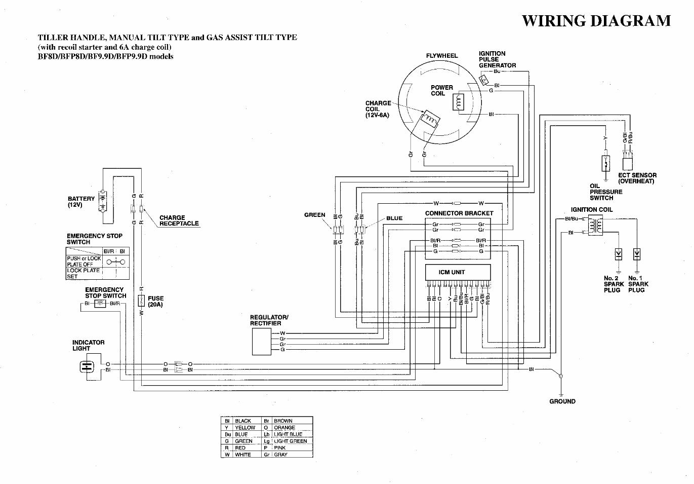
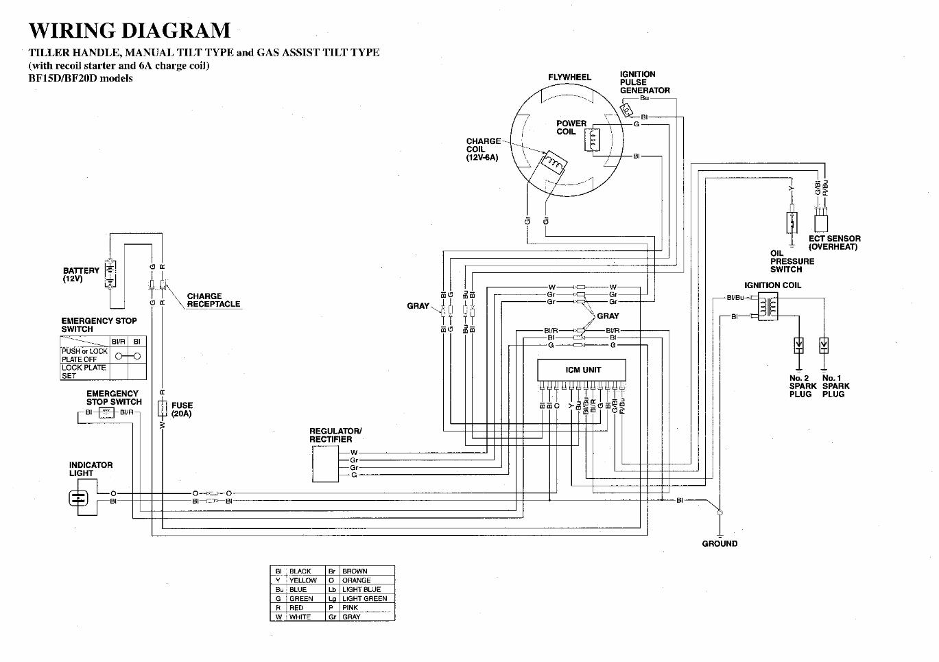
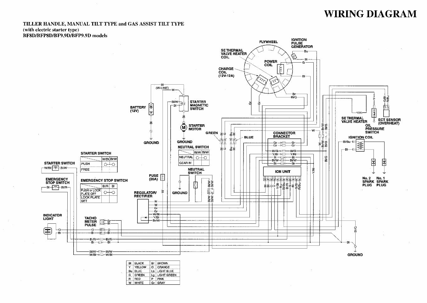


![[Flip-Side] 7. IC Engine Exhaust Emissions](https://static.documents.pub/doc/80x56/56d6c06d1a28ab30169a58cc/flip-side-7-ic-engine-exhaust-emissions.jpg)


