The ESO transportable LGS Unit for measurements of the LGS photon return and other experiments D. Bonaccini Calia 1a , I.Guidolin a , A.Friedenauer b , M.Hager b , V.Karpov c , T.Pfrommer a , R. Holzlöhner a , S.Lewis a , W.Hackenberg a , G.Lombardi a , M.Centrone d and F.Pedichini d a European Southern Observatory, Karl-Schwarzshild-Str.2, 85748 Garching, Germany, b Toptica Photonics AG, Lochhamer Schlag 19, D-82166 Gräfelfing, Germany c MPB Communications Montreal, Quebec, Canada d Osservatorio Astronomico di Roma, Via Frascati 33, 00040 Monte Porzio Catone (RM), Italy ABSTRACT Sodium laser guide stars (LGS) are used, or planned to be used, as single or multiple artificial beacons for Adaptive Optics in many present or future large and extremely large telescopes projects. In our opinion, several aspects of the LGS have not been studied systematically and thoroughly enough in the past to ensure optimal system designs. ESO has designed and built, with support from industry, an experimental transportable laser guide star unit, composed of a compact laser based on the ESO narrow-band Raman Fiber Amplifier patented technology, attached to a 30cm launch telescope. Besides field tests of the new laser technology, the purpose of the transportable unit is to conduct field experiments related to LGS and LGS-AO, useful for the optimization of future LGS-AO systems. Among the proposed ones are the validation of ESO LGS return flux simulations as a function of CW and pulsed laser properties, the feasibility of line-of- sight sodium profile measurements via partial CW laser modulation and tests of AO operation with elongated LGS in the EELT geometry configuration. After a description of the WLGSU and its main capabilities, results on the WLGSU commissioning and LGS return flux measurements are presented. Keywords: Laser guide stars, lasers, sodium scattering, adaptive optics, extremely large telescopes 1. INTRODUCTION Adaptive Optics systems with Laser Guide Stars (LGS-AO) as reference sources are used in several observatories, including the Very Large Telescope (VLT) operated by ESO. Second generation LGS-AO facilities are being built for the 8–10m class telescopes. Third-generation LGS-AO systems are being conceived for the proposed Extremely Large Telescopes, in which the use of laser guide stars will be standard operation, in association with increasingly complex AO systems. It is our opinion that there is a strong need to mature the technologies related to LGS so that their use may become routine and sufficiently optimized. The ELT LGS-AO systems will be even more challenging and such studies are strategic in the next years, when the system design will be defined. In the past two years we have built together with industry a transportable Laser Guide Star Unit, i.e. a compact system, in which an experimental 20W CW laser at 589nm based on the ESO patented Fiber Raman Amplifier (ERFA) technology is attached directly to a launch telescope mounted on high precision pointing motors. The so-called “Wendelstein Laser 1 [email protected]; phone: +49 89 3200 6567; www.eso.org
Transcript
The ESO transportable LGS Unit for measurements of the LGS photon return and other experiments
D. Bonaccini Calia1a, I.Guidolina, A.Friedenauerb, M.Hagerb, V.Karpovc, T.Pfrommera, R. Holzlöhnera, S.Lewisa, W.Hackenberga, G.Lombardia, M.Centroned and F.Pedichinid
cMPB Communications Montreal, Quebec, Canada dOsservatorio Astronomico di Roma, Via Frascati 33, 00040 Monte Porzio Catone (RM), Italy
ABSTRACT
Sodium laser guide stars (LGS) are used, or planned to be used, as single or multiple artificial beacons for Adaptive Optics in many present or future large and extremely large telescopes projects.
In our opinion, several aspects of the LGS have not been studied systematically and thoroughly enough in the past to ensure optimal system designs.
ESO has designed and built, with support from industry, an experimental transportable laser guide star unit, composed of a compact laser based on the ESO narrow-band Raman Fiber Amplifier patented technology, attached to a 30cm launch telescope.
Besides field tests of the new laser technology, the purpose of the transportable unit is to conduct field experiments related to LGS and LGS-AO, useful for the optimization of future LGS-AO systems. Among the proposed ones are the validation of ESO LGS return flux simulations as a function of CW and pulsed laser properties, the feasibility of line-of-sight sodium profile measurements via partial CW laser modulation and tests of AO operation with elongated LGS in the EELT geometry configuration.
After a description of the WLGSU and its main capabilities, results on the WLGSU commissioning and LGS return flux measurements are presented.
Adaptive Optics systems with Laser Guide Stars (LGS-AO) as reference sources are used in several observatories, including the Very Large Telescope (VLT) operated by ESO. Second generation LGS-AO facilities are being built for the 8–10m class telescopes. Third-generation LGS-AO systems are being conceived for the proposed Extremely Large Telescopes, in which the use of laser guide stars will be standard operation, in association with increasingly complex AO systems.
It is our opinion that there is a strong need to mature the technologies related to LGS so that their use may become routine and sufficiently optimized. The ELT LGS-AO systems will be even more challenging and such studies are strategic in the next years, when the system design will be defined.
In the past two years we have built together with industry a transportable Laser Guide Star Unit, i.e. a compact system, in which an experimental 20W CW laser at 589nm based on the ESO patented Fiber Raman Amplifier (ERFA) technology is attached directly to a launch telescope mounted on high precision pointing motors. The so-called “Wendelstein Laser
Guide Star Unit” (WLGSU) has been designed, assembled, tested in the ESO laboratory and finally commissioned successfully in the summer of 2011, in Bavaria, Germany. The goal of the WLGSU is to field test the laser technology while supporting some strategic experiments for the LGS-AO technologies.
The ESO LGS group has identified four areas in which to propose further progressed in the next 3–4 years, in collaboration with other observatories, institutes and industry:
1. Reliable, turn-key 589nm laser sources with 20+ W CW. To this goal some of us worked actively to pursue compact, reliable and simple lasers in past years, with the development of the ESO Raman Fiber Amplifier1. This development has brought patents, licensing to industry, and lately the production of an experimental laser2 of 20W CW, which is part of the WLGSU. The laser has been extensively tested in the laboratory and in the field, as reported below. Beyond the experimental laser, contracts with industry aim at delivering the first well-engineered turn-key laser unit in 2012 3, which is the first of four being procured for the ESO 4LGSF of the Adaptive Optics Facility project4.
2. Optimization of the LGS return flux (RF) efficiency. Besides thorough theoretical simulations done in the past three years5,6,7, using quantum mechanical Bloch equations to model the interaction of the laser radiation with the sodium atoms in the mesosphere, experiments are needed to validate the models and investigate which laser format yields the highest return flux efficiency. This is important for the next generation lasers of LGS-AO, but also has the potential to improve the RF of currently used laser systems by small modifications of current lasers. Suitable experiments are proposed in this article. They require different laser types and some can currently only be accomplished using the WLGSU in collaboration with existing LGS-AO systems at different observatories.
3. Sodium centroid fast variability: the recent results obtained at the University of British Columbia’s Large Zenith Telescope (LZT) 6m liquid mirror telescope8 indicate fast mesospheric sodium centroid variability and a strong spatial decorrelation between LGS pointing at different field angles9. This may be detrimental for the ELTs given their large collecting diameter. The problem can be addressed in two ways: With pulsed lasers of a format allowing pulse tracking in the mesosphere or, during operation, by measuring at fast rates the sodium profile generating each LGS. The feasibility of the latter approach is one of the experiments proposed below, using the WLGSU at the LZT.
4. Operation of the LGS-AO with highly elongated LGS: besides simulations and laboratory tests10, we think field experiments11 are mandatory to validate and optimize LGS-AO performance. We note that for the E-ELT the LGS-AO will be used in side-launch geometry, with maximum LGS elongation on the wavefront sensor subapertures. This geometry has been studied but needs field test validation with the real sodium layer behavior. The tests described below may be carried out using the WLGSU together with the CANARY system12 on the WHT telescope in La Palma.
2. THE WENDELSTEIN LASER GUIDE STAR UNIT
A description of the 589nm, 20W CW laser used in the WLGSU has been already given, along with its main test results13, and it will not be repeated here.
The WLGSU itself consists of a launch telescope system, a laser head attached to it, motorized ALT-AZ mounts, two electronic cabinets and one chiller unit. The athermalized refractive axial launch telescope system is based on a carbon fiber structure holding two beam expander units in series. By choosing for the carbon fiber tube a CTE of 3.1x10⁻⁶ the optics is compensated for temperature-dependent focus.
The first beam expander unit (12x) made by Sill Optics (silloptics.de) transforms a 1.25mm diameter beam into a 15 mm beam. Focus can be adjusted via motorized control, while the zoom factor can be changed manually in the range 12x–15x. The second beam expander (20x) was made based on the ESO design by the company Astelco (astelco.com). It is called Optical Tube Assembly (OTA), a Galileian lens design using a 380mm diameter aspheric lens. The combined optic modules transform a 1.25mm diameter laser beam into a 300mm diameter beam. The design chosen is very tolerant towards alignment and displacement errors between the two beam expander units. A similar modular concept has been used for the 4LGSF launch telescope system. A byproduct of the WLGSU was to prototype and to validate the 4LGSF OTA optical system.
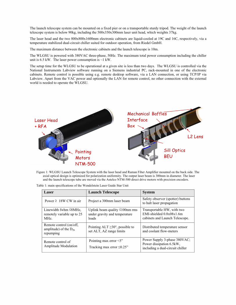
The launch telescope system can be mounted on a fixed pier or on a transportable sturdy tripod. The weight of the launch telescope system is below 90kg, including the 500x350x300mm laser unit head, which weights 37kg.
The laser head and the two 800x800x1600mm electronic cabinets are liquid-cooled at 19C and 16C, respectively, via a temperature stabilized dual-circuit chiller suited for outdoor operation, from Riedel GmbH.
The maximum distance between the electronic cabinets and the launch telescope is 10m.
The WLGSU is powered with 380VAC three-phase, 50Hz. The maximum total power consumption including the chiller unit is 6.5 kW. The laser power consumption is ~1 kW.
The setup time for the WLGSU to be operational at a given site is less than two days. The WLGSU is controlled via the National Instruments Labview software running on a Siemens industrial PC, rack-mounted in one of the electronic cabinets. Remote control is possible using e.g. remote desktop software, via a LAN connection, or using TCP/IP via Labview. Apart from the VAC power and optionally the LAN for remote control, no other connection with the external world is needed to operate the WLGSU.
Figure 1: WLGSU Launch Telescope System with the laser head and Raman Fiber Amplifier mounted on the back side. The axial optical design is optimized for polarization uniformity. The output laser beam is 300mm in diameter. The laser and the launch telescope tube are moved via the Astelco NTM-500 direct drive motors with precision encoders.
Table 1: main specifications of the Wendelstein Laser Guide Star Unit
Laser Launch Telescope System
Power ≥ 18W CW in air Project a 300mm laser beam Safety observer (spotter) buttons to halt laser propagation
Linewidth fwhm ≤8MHz, remotely variable up to 25 MHz.
Uplink beam quality ≤100nm rms under gravity and temperature loads
Transportable HW, with two EMI-shielded 0.8x08x1.6m cabinets and Launch Telescope.
Remote control (on/off, amplitude) of the D2b repumping
Pointing ALT ≥30°, possible to set ALT, AZ range limits
Distributed temperature sensor and coolant flow-meters
Remote control of Amplitude Modulation
Pointing max error <5”
Tracking max error ≤0.25”
Power Supply 3-phase 380VAC; Power dissipation 6.5kW, including a dual-circuit chiller
Pointing Motors
NTM-500
Laser Head
+ RFA
Sill Optics BEU
L2 Lens
Baffles Mechanical Interface Box
Remote control of emitted light polarization state
ALT-AZ mount, on a pier or on a sturdy tripod
WLGSU setup time ≤ 2 days
Cold startup time ≤ 0.5 hour
Wavelength setting and stabilization ±20 MHz
Side finder with CCD camera for pointing model acquisitions
Class IV laser Safety measures for the laser system
Figure 2: Left: the WLGSU launch telescope and laser head, being mounted on a sturdy tripod for tests at ESO headquarters. Right: optical quality tests done under temperature loads of the full Launch Telescope System optomechanics. In the operational temperature range 0-15°C the wavefront rms across the full aperture is 30nm. The soaked temperature tests (dashed line) indicate a good athermalized behavior, with a constant wavefront error. The transient temperature tests, at 0.7°C/h, show degradation up to 38nm rms in the operational range at the VLT, against an allocated budget for the launch telescope system of 70nm rms.
3. OBSERVATION SETUP
For the observations a 40cm receiver telescope is placed within few tens of meters from the WLGSU, to do V-band and R-band photometry of the Laser Guide Star. The architecture and software allow efficient control of the pointing of the two small telescopes, of the laser settings and of the measurements acquisition. The observing setup and software functionalities prepared are an outcome of the Commissioning phase, in which the observing modes have been tested.
As shown in the schematic of Figure 4 below, the LGS test assembly allows to control remotely the laser, the launch telescope, the receiver telescope and the CCD camera. The observations normally include toggling between different laser emission properties, such as
repumping line strength, emission linewidth, polarization, laser power, while acquiring images of the LGS and of surrounding photometric stars using calibrated Johnson filters (Figure 3). V-band and R-band filters are used, their transmission at 589nm was
pre-calibrated. Using aperture photometry and properly calibrating the data, the LGS flux on the ground is derived.
0
10
20
30
40
50
60
70
0 5 10 15 20 25
WFE (nm rms)
Temperature (C)
WLTS WFE [300mm] vs Temp
Soaked Temp
Transient Temp 0.7C/h
Figure 3: V-band CCD image of a star field with the LGS obtained during commissioning of the WLGSU. The field of view is 10.5x7.1 arcmin, with a sampling of 0.29”/pxl. The launch- receiver telescope distance was 13 m.
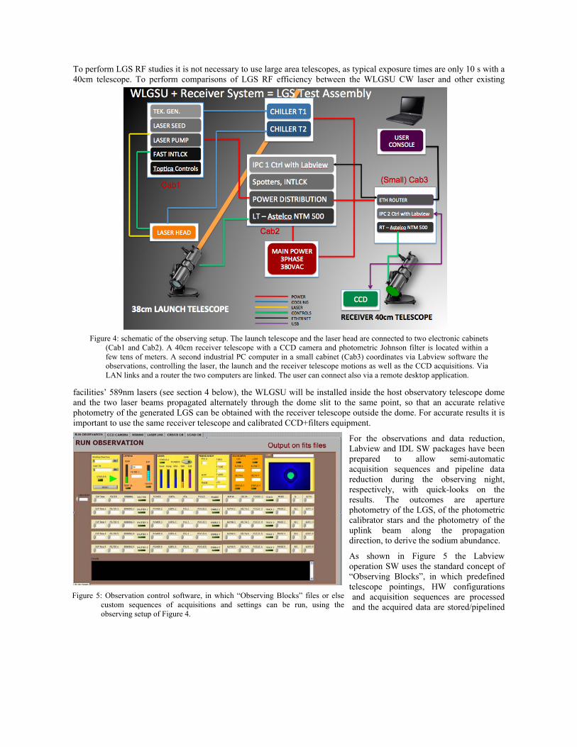
To perform LGS RF studies it is not necessary to use large area telescopes, as typical exposure times are only 10 s with a 40cm telescope. To perform comparisons of LGS RF efficiency between the WLGSU CW laser and other existing
facilities’ 589nm lasers (see section 4 below), the WLGSU will be installed inside the host observatory telescope dome and the two laser beams propagated alternately through the dome slit to the same point, so that an accurate relative photometry of the generated LGS can be obtained with the receiver telescope outside the dome. For accurate results it is important to use the same receiver telescope and calibrated CCD+filters equipment.
For the observations and data reduction, Labview and IDL SW packages have been prepared to allow semi-automatic acquisition sequences and pipeline data reduction during the observing night, respectively, with quick-looks on the results. The outcomes are aperture photometry of the LGS, of the photometric calibrator stars and the photometry of the uplink beam along the propagation direction, to derive the sodium abundance.
As shown in Figure 5 the Labview operation SW uses the standard concept of “Observing Blocks”, in which predefined telescope pointings, HW configurations and acquisition sequences are processed and the acquired data are stored/pipelined
Figure 5: Observation control software, in which “Observing Blocks” files or elsecustom sequences of acquisitions and settings can be run, using theobserving setup of Figure 4.
Figure 4: schematic of the observing setup. The launch telescope and the laser head are connected to two electronic cabinets (Cab1 and Cab2). A 40cm receiver telescope with a CCD camera and photometric Johnson filter is located within a few tens of meters. A second industrial PC computer in a small cabinet (Cab3) coordinates via Labview software the observations, controlling the laser, the launch and the receiver telescope motions as well as the CCD acquisitions. Via LAN links and a router the two computers are linked. The user can connect also via a remote desktop application.
with the data reduction software.
4. LGS RETURN FLUX EXPERIMENTS
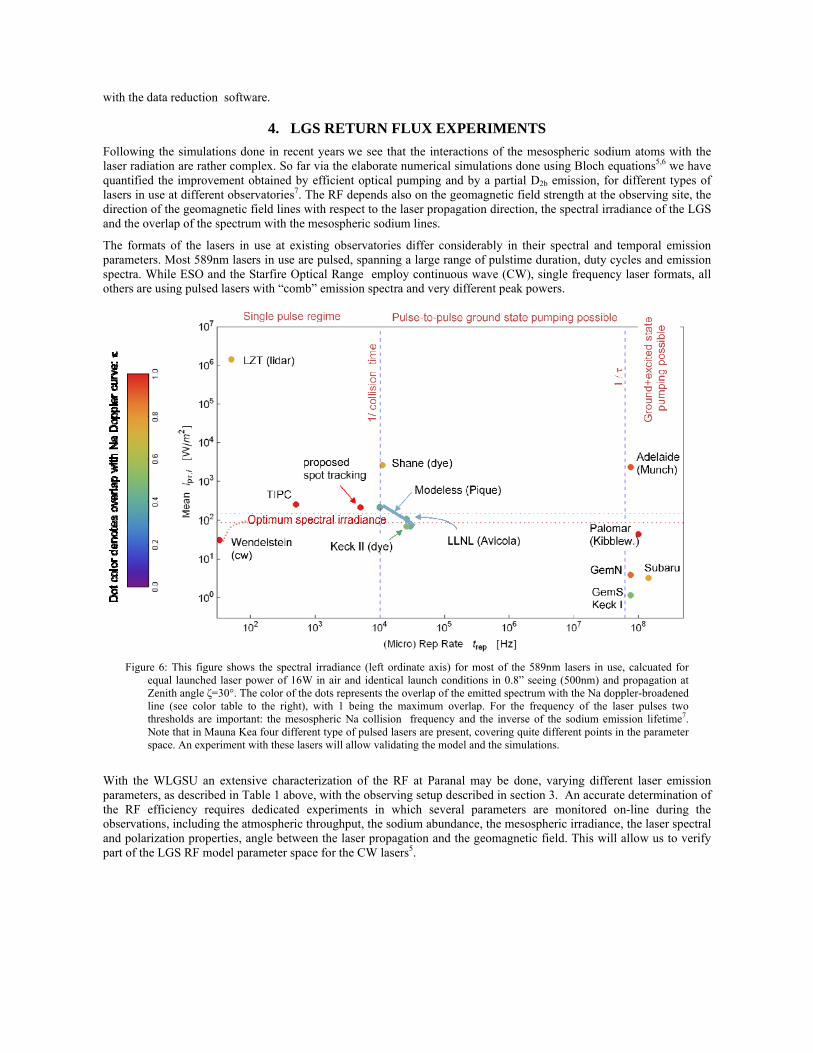
Following the simulations done in recent years we see that the interactions of the mesospheric sodium atoms with the laser radiation are rather complex. So far via the elaborate numerical simulations done using Bloch equations5,6 we have quantified the improvement obtained by efficient optical pumping and by a partial D2b emission, for different types of lasers in use at different observatories7. The RF depends also on the geomagnetic field strength at the observing site, the direction of the geomagnetic field lines with respect to the laser propagation direction, the spectral irradiance of the LGS and the overlap of the spectrum with the mesospheric sodium lines.
The formats of the lasers in use at existing observatories differ considerably in their spectral and temporal emission parameters. Most 589nm lasers in use are pulsed, spanning a large range of pulstime duration, duty cycles and emission spectra. While ESO and the Starfire Optical Range employ continuous wave (CW), single frequency laser formats, all others are using pulsed lasers with “comb” emission spectra and very different peak powers.
Figure 6: This figure shows the spectral irradiance (left ordinate axis) for most of the 589nm lasers in use, calcuated for equal launched laser power of 16W in air and identical launch conditions in 0.8” seeing (500nm) and propagation at Zenith angle ζ=30°. The color of the dots represents the overlap of the emitted spectrum with the Na doppler-broadened line (see color table to the right), with 1 being the maximum overlap. For the frequency of the laser pulses two thresholds are important: the mesospheric Na collision frequency and the inverse of the sodium emission lifetime7. Note that in Mauna Kea four different type of pulsed lasers are present, covering quite different points in the parameter space. An experiment with these lasers will allow validating the model and the simulations.
With the WLGSU an extensive characterization of the RF at Paranal may be done, varying different laser emission parameters, as described in Table 1 above, with the observing setup described in section 3. An accurate determination of the RF efficiency requires dedicated experiments in which several parameters are monitored on-line during the observations, including the atmospheric throughput, the sodium abundance, the mesospheric irradiance, the laser spectral and polarization properties, angle between the laser propagation and the geomagnetic field. This will allow us to verify part of the LGS RF model parameter space for the CW lasers5.
Moreover we propose measurements of relative LGS RF at Mauna Kea with the WLGSU and the four different pulsed lasers on site. The measurement can only be done in collaboration between the Keck, Subaru and Gemini observatories, using the four different lasers in four different technical nights, for a total of 2 weeks of activity. Using the same receiver small telescope and its calibrated camera, alternating every few seconds the LGS generated by one laser with the LGS generated by the other laser on the same mesospheric point, we ensure very good relative measurements. This would allow validating the simulations for the more complex case of pulsed lasers. The benefit for the astronomical community will be significant, since the numerical Bloch equation RF model will then be validated and the related computer code is publically available.
The strategic importance of having validated RF simulations for CW and pulsed formats, in terms of maturing the LGS technologies, is twofold: (1.) the code will allow determining numerically which is the laser format giving the best LGS RF/W emitted, and (2.) the code will allow to decide upon possible fine tuning of existing lasers to increase their RF. Also for the extremely large telescope projects, for which the laser procurement is several years ahead, it will be important to have reliable predictions/simulations, which can help us selecting the best laser formats.
Summarizing we propose two sets of experiments with the aim to complete/validate the end-to-end model of the LGS generation and its RF on the ground:
1. set of LGS photometric measurements in Paranal to be done with the WLGSU setup, with at least one observing week per season and for different parameters of the CW laser emission.
2. Relative and absolute photometry measurements in Mauna Kea, toggling LGS generated by the WLGSU CW laser and one of the host telescope pulsed lasers, one technical night at a time for four technical nights in total.
4.1 RF measurements during the WLGSU commissioning
During the commissioning in Bavaria of the WLGSU, done in 2011 using the 60cm receiver telescope at the Ottobeuren AVSO observatory (www.avso.de), some RF measurements have been obtained with good conditions. We could not measure or monitor the sodium abundance with sufficient confidence. We obtained a temporary no-fly zone from the German aviation authorities, limiting the pointing to ALT ≥ 45°. We had a successful commissioning and obtained encouraging preliminary results, which we report hereafter in some greater detail. We also ran numerical simulations to predict the expected return flux.
Table 2: parameters used in the numerical simulations predicting the return flux at the AVSO observatory
Parameter Symbol Value Comment
Laser power PL 16 W Beam power in air at launch telescope output. Excludes the power in the “anti”-D2b sideband!
D2b repumping power fraction q 0.12, 0 Optimum value 0.12, derived5
Repumping frequency offset Δf 1.710 GHz Optimum value derived7
Geomagnetic field strength B 0.4597 G AVSO site, B value at 93 km altitude; From IGRF model
Geomagnetic field direction α, β 63.7°, 1.7° ALT, AZ angle clockwise from South
Atmospheric transmission Ta 0.75 Assumed one-way transmission at 589 nm and zenith in the absence of haze and cirrus clouds
Na column density CNa 4 × 10¹³ m–2 Median value in the observing season
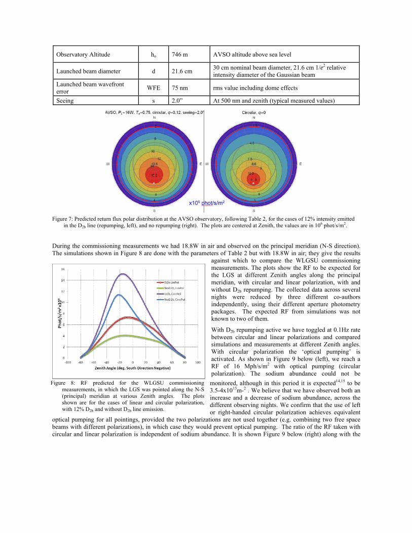
Observatory Altitude ho 746 m AVSO altitude above sea level
Launched beam diameter d 21.6 cm 30 cm nominal beam diameter, 21.6 cm 1/e2 relative intensity diameter of the Gaussian beam
Launched beam wavefront error
WFE 75 nm rms value including dome effects
Seeing s 2.0” At 500 nm and zenith (typical measured values)
During the commissioning measurements we had 18.8W in air and observed on the principal meridian (N-S direction). The simulations shown in Figure 8 are done with the parameters of Table 2 but with 18.8W in air; they give the results
against which to compare the WLGSU commissioning measurements. The plots show the RF to be expected for the LGS at different Zenith angles along the principal meridian, with circular and linear polarization, with and without D2b repumping. The collected data across several nights were reduced by three different co-authors independently, using their different aperture photometry packages. The expected RF from simulations was not known to two of them.
With D2b repumping active we have toggled at 0.1Hz rate between circular and linear polarizations and compared simulations and measurements at different Zenith angles. With circular polarization the ‘optical pumping’ is activated. As shown in Figure 9 below (left), we reach a RF of 16 Mph/s/m2 with optical pumping (circular polarization). The sodium abundance could not be
monitored, although in this period it is expected14,15 to be 3.5-4x10¹³m-2 . We believe that we have observed both an increase and a decrease of sodium abundance, across the different observing nights. We confirm that the use of left or right-handed circular polarization achieves equivalent
optical pumping for all pointings, provided the two polarizations are not used together (e.g. combining two free space beams with different polarizations), in which case they would prevent optical pumping. The ratio of the RF taken with circular and linear polarization is independent of sodium abundance. It is shown Figure 9 below (right) along with the
Figure 7: Predicted return flux polar distribution at the AVSO observatory, following Table 2, for the cases of 12% intensity emitted in the D2b line (repumping, left), and no repumping (right). The plots are centered at Zenith, the values are in 106 phot/s/m2.
Figure 8: RF predicted for the WLGSU commissioningmeasurements, in which the LGS was pointed along the N-S(principal) meridian at various Zenith angles. The plotsshown are for the cases of linear and circular polarization,with 12% D2b and without D2b line emission.
simulations (dotted blue line), which lie about 10% higher. As shown, optical pumping increases the RF most effectively when pointing parallel to the geomagnetic field lines (hotspot). Another set of WLGSU commissioning observations has been dedicated to a first evaluation of the D2b line repumping effectiveness for different laser polarizations and Zenith angles. The measurements results are shown in Figure 10. Again we do not know for sure the sodium column abundance, but the ratio of RF is independent of it. We present here the measurements done in the hotspot (~17° S) for optical pumping and ~59° away from it (42° N), where the RF becomes independent of irradiance in the mesosphere, hence seeing. We define the repumper RF gain as the ratio of the RF with and without D2b emission, for each polarization case. Again, this ratio is independent of sodium abundance. At Z= 42° N the predicted ratio of RF is shown in the table insert on the right of Figure 10. The agreement between the simulations and the measurements is excellent in this case.
Figure 9: Left: RF as a function of laser optical polarization. The data were taken toggling between linear and circular polarization every ten seconds, and averaged. Different Zenith angles on the principal meridian have been sampled, for a total run of about 3 hours. The 12% D2b repumping was active. The dashed or dotted blue curves represent the simulations results. Right: the ratio of the RF obtained with circular and linear polarization vs Zenith angle is an indicator of the effectiveness of the optical pumping, and is independent from the sodium abundance. It does however depend on the irradiance, hence on the seeing conditions.
Figure 10: Test of the effectiveness of the D2b re-pumping with linear and circular polarizations (see legend), for the hotspot region at
AVSO (left) and for Zenith=42° (right). For each Zenith position and setting, 21 CCD frames have been averaged. At Z=42° the RF is quite independent of irradiance, i.e. seeing or spot size. The RF gain displayed in the insert table is the averaged ratio of RF with and without repumping, and this ratio is independent of the sodium abundance. Note that re-pumping is more useful when the propagation direction is away from the geomagnetic field lines (right). The progressive reduction of return flux in the plots is likely due to the sodium column abundance reduction across the night. As it can be seen in the insert table in the picture to the right, there is good agreement between simulations and measurements of the repumper gains.
Z = 42 Repumper Gains in RF Simulations Measurement
CircularPol 148.9% 142.5% LinearPol 148.2% 143.5%
5. SODIUM LAYER FAST VARIABILITY: ON-LINE PROFILES
Rapid variations of the sodium layer vertical profile centroid have been found8,9 and are a potential problem for the extremely large telescopes using CW lasers. Whether the lasers are launched from the side or at the center of the telescope pupil, the large and rapid variations of the sodium layer mean altitude can induce large errors on some detected modes of the LGS wavefront sensor. We propose to derive at rates <1Hz the sodium profile pertaining to each LGS using fast amplitude modulation of the CW laser light at low modulation depth16, A similar architecture had been implemented at the VLT17 on the PARSEC laser. Contrary to the VLT implementation, in the feasibility experiment proposed to be conducted at the LZT, we will modulate only 10% of the WLGSU CW laser amplitude using an internal bulk optics Acousto-Optic Modulator. A pseudo-random bit pattern of amplitude modulation is applied to the uplink laser beam generated by the WLGSU, while the 6m LZT receiver telescope feeds the LGS to the photon counter at its focal plane. Via precise timing and a scaler electronic board, the sodium profile is retrieved via cross-correlation of the generated pattern and the received time series of photon counts. In the proposed experiment at the LZT a sodium profile should be produced every 0.26s, with SNR
comparable to the VLT CW Lidar. The LZT high-resolution Lidar system will be used as ‘truth’ sodium profile sensor, to verify that the sodium profiles obtained are valid. As in the case of the existing VLT CW Lidar, in an ELT application the 589nm light left over from the LGS dichroic located in the Wavefront Sensor optical path may be used to feed the photon counter, i.e. ~ 1.5% of the LGS photons collected by the full ELT aperture. By comparison with the photon counter fluxes measured at the VLT Lidar, such a system should produce one sodium profile every 0.3s. The ~MHz amplitude modulation, with pseudo-random patterns of the 10% intensity of the uplink laser will be transparent to the adaptive optics LGS wavefront sensor, which has sampling rates below 1 kHz.
6. LGS AO FIELD TESTS WITH HIGHLY ELONGATED LGS
The baseline of the Extremely Large Telescopes Adaptive Optics is to use CW lasers, which will produce highly elongated LGS on the wavefront sensor. A field test of LGS-AO is proposed11, in which we will use the WLGSU with the CANARY AO system at the William Herschel Telescope (WHT) on La Palma, Canary Islands. As risk minimization activity, it is quite important to field test the operation of LGS-AO systems with strongly elongated LGS obtained from the real sodium layer, as it has never been done before and it is in the scope of the CANARY as EELT pathfinder instrument12.
Figure 11: Sodium layer profile obtained with the VLT CWLidar17. Similar sodium profiles will be obtained in theproposed experiment, in which however only 10% ofthe 20W CW laser will be amplitude-modulated. On theright, the scheme proposed, with the LZT as receiver.
By placing the transportable WLGSU at different distances from the 4.2m WHT telescope we will be able to produce elongated LGS on the CANARY wavefront sensor, representing on the 4.2m WFS different sets of subapertures on the EELT (see Figure 12). The experiment will initially compare in open loop the NGS ‘true’ wavefront, acquired with the CANARY NGS WFS, with the LGS wavefront acquired with the CANARY LGS WFS. We will record simultaneously data from the two wavefront sensors (NGS and LGS), as well as the sodium vertical profile, taken either with a side telescope looking at the LGS ‘plume’ (see Figure 13) or with the CW Lidar method, explained in section 5. As a goal we will repeat the measurement runs with the AO loop closed on the NGS. To note is that the LGS cone effect on the 4.2m WHT telescope is sufficiently small since the sodium LGS is at ≥90 km, hence it will not affect the experiment outcome. The LGS WFS on CANARY will measure a large wavefront tilt signal component coming from the differential elongation of the LGS in its subapertures (see Figure 12, right). This tilt is the main error component, although not the only one, due to the LGS mesospheric ‘plume’. Whenever the sodium vertical profile centroid will change altitude, these related wavefront error contributions will change. By monitoring the sodium distribution profile on-line at a rate of ~1Hz during the experiment we will be able to subtract its contribution from the measured LGS wavefront, and then compare the measurement of the LGS wavefront with the ‘true’ NGS wavefront. When the CANARY AO loop on the NGS will be closed, we will measure the residual LGS WFS signal, assess its error contributions and project the
obtained results for different distances of the WHT and WLGSU, on the evaluation of the ELT LGS-AO performance. During the experiment campaigns the distance of the WLGSU from the WHT pupil will be chosen according to the EELT geometry.
7. CONCLUSIONS
Using the narrowband Fiber Raman amplifier technology and a launch telescope, both with configurations similar to what will be used for the ESO AOF 4LGS Facility, we have built a transportable Laser Guide Star Unit to conduct experiments on LGS aspects relevant to mature the use of the LGS in LGS-adaptive optics. The laser has built-in the possibility to vary wavelength, linewidth, polarization to arbitrary states, pulse modulation, and D2b repumping levels. The launch telescope system is athermalized and maintains a beam quality better than 40nm rms under environmental loads observed at the VLT. The integration and commissioning of the WLGSU were successfully completed in summer 2011, and the first very encouraging results on the LGS return flux from the 20W CW laser have been obtained and presented. With the WLGSU we propose to conduct experiments in Paranal and then at different telescopes on Mauna Kea having different pulsed laser formats, to be able to validate the return flux simulations for CW and pulsed lasers. The ultimate goal is to find out from numerical simulations, which are the laser parameters giving maximum LGS return flux.
Figure 13: In the proposed experiment with WLGSU at WHT, thesodium profile will be acquired in parallel with the wavefrontmeasurements done with the NGS and LGS WFS
Figure 12:By placing the WLGSU at different distances from theWHT we will reproduce the LGS elongations seen by differentsections of the EELT (left). The differential LGS elongationacross the Shack-Hartmann wavefront sensor subapertures willproduce a large tilt signal (right), which is variable with thevariation of the sodium mean altitude. By knowing on-line thesodium profile at a rate ~1Hz, we will subtract the effect.
Specifically for the ELT scenarios we further propose two experimental campaigns. The first one is to be conducted at the UBC LZT Lidar telescope, jointly with the group of Prof. Hickson, with the aim to demonstrate that sodium profiles at rates >1Hz may be obtained for each LGS on the EELT, continuously during operations. Those LGS sodium profiles will be very useful to limit the effects of the measured fast variability of the sodium layer. The outcome of this experiment may lead to the development of a prototype CW laser Lidar for the EELT. The second experimental campaign is aimed at field validating the LGS-AO wavefront sensing, when the LGS image is elongated on the wavefront sensor, as it will be for the EELT. The experiment is proposed to be done at the WHT telescope in collaboration with Durham University and the Observatoire de Paris group, using the CANARY system. Given the EELT timescales, it is in our opinion strategically important that these risk reduction field experiments are concluded and the results are obtained by 2016.
[2] Bonaccini Calia,D., Feng, Y., Hackenberg, W., Holzlöhner, R., Taylor, L. and Lewis, S.: “Laser development for sodium laser guide stars at ESO”, in the ESO Messenger no. 139, pp.12-19 (2010), http://www.eso.org/sci/publications/messenger/archive/no.139-mar10/messenger-no139-12-19.pdf
[3] Friedenauer, A., Ernstberger, B., Kaenders, W., Karpov, V., Wie, D. and Clements, W.R.L.: in this Proc. SPIE 8447, (2012).
[4] Arsenault, R. et al: “The ESO adaptive Optics Facility: integration completed and readiness for system tests” in this Proc. SPIE Vol. 8447 (2012).
[5] Holzlöhner, R., Rochester, S.M., Bonaccini Calia, D., Budker, D., Higbie, J.M. and Hackenberg, W.: “Optimization of cw sodium laser guide star efficiency“, http://arxiv.org/abs/0908.1527v2
[6] Rochester, S. et al: JOSA B, Vol. 29, pp. 2176-2188 (2012).
[7] Holzlöhner, R., Rochester, S.M., Bonaccini Calia, D., Budker, D., Pfrommer T. and Higbie, J.M.:., “Simulations of pulsed sodium laser guide stars: an overview”, in this Proc. SPIE Vol. 8447, (2012).
[8] Pfrommer, T. and Hickson, P: “High-resolution lidar observations of mesospheric sodium and implications for adaptive optics”, JOSA A Vol 27, no. 11, A97-105 (2010)
[9] Pfrommer, T. and Hickson, P.: “ Mesospheric Sodium Structure Variability and its Impact on Adaptive Optics”, in this Proc SPIE 8447 (2012).
[10] Lardiere,O, , Conan,R., Clare, R., Bradley,C. and Hubin,N, “Performance comparison of centroiding algorithms for laser guide star wavefront sensing with extremely large telescopes”, Applied Optics, Vol. 49, Issue 31, pp. G78-G94 (2010), http://dx.doi.org/10.1364/AO.49.000G78 .
[11] Gratadour, D., Rousset, G., Gendron, E., Morris, T. J., Myers, R.M., Bonaccini Calia, D., Pfrommer, T.: “Toward an ELT-scale sodium LGS wavefront sensing on-sky experiment“, in this Proc. SPIE 8447 (2012).
[12] Scope of the JRA1 WP1.2 CANARY Pathfinder, http://www.eso.org/sci/facilities/develop/ao/fp7/index.html
[13] Bonaccini Calia, D., Friedenauer, A., Protopopov, V., Guidolin, I, Taylor, L.R, Karpov, V.I., Hager, M., Clements, W.L.R, Ernstberger, B., Lewis, S. and Kaenders, W.G., “PM fiber lasers at 589nm: a 20W transportable laser system for LGS RF studies ” Proc SPIE Vol 7736, 65 (2010).
[14] Fussen,D et al: “A global climatology of the mesospheric sodium layer from GOMOS data during the 2002-2008 period”, Atmos. Chem. Phys. Discuss. Vol 10, 6069-6127
[15] Xiong, H., Gardner, C.S., Liu, A.Z: “Seasonal and Nocturnal Variations of the Mesospheric Sodium Layer at Starfire Optical Range, New Mexico”, Chinese Journal of Geophysics, Vol. 46, no.3, 432-437 (2003)
[16] Butler, D.J et al: “Measuring the Absolute Height and Profile of the Mesospheric Sodium Layer using a Continuous Wave Laser”, A&A http://arXiv.org/abs/astro-ph/0303299v2 (2003)
[17] Butler, D.J. et al: “Design of the Atmospheric Sodium Profiler for the VLT Laser Guide Star”, SPIE Proc. 4839, 456 (2003) DOI: http://dx.doi.org/10.1117/12.45886