MANAGEMENT The evolution of a modern telecommunications network to the year 2000 and beyond Sydney O'Hara, B.Sc, Ph.D., C.Eng., F.I.E.E. Indexing terms: Engineering administration and management, Project and production engineering Abstract: An example of how a general management goes about the formulation of long-term policy and invest- ment programmes, where rapidly changing technology is linked to rapidly changing needs in the market place, in a newly competitive environment, in a time frame extending over the next 15 years. British Telecom is in the middle of an investment programme that will transform the analogue network into a digital system. The initial objective was to reduce operating costs, but market demands for new services require additional and substantial investment decisions, with the total running at the rate of £1 billion per year for at least the next five years. The present 'layered' network has been built up by adding services. As the 'product life cycles' of the several technol- ogies reach out into the future, new possibilities emerge such as mobile radio where the cellular network can be divided down to accomodate millions of subscribers and, in the longer term, the realisation of an all digital main network serving the business environment, with local intelligence in each subscriber's PABX. As an example of the pace of technology, a 15000 line exchange as now manufactured is based on the technology of about six years ago, and occupies 15 racks. With currently developed technologies, this can be reduced to 3 racks. Extrapolating to techniques of high-density wafer integration, by 1995 only two circuit boards will be required, a small fraction of one rack. The market needs are changing, and a wide adoption of electronic funds transfer by retailers will generate a heavy demand for short duration calls, increasing the processing load. The area of limited improvement is the production of software, where costs are being reduced by a factor of only two per decade. Glossary of acronyms MSN = multi-service network S x S = step-by-step PSS = packet switched service PSN = packet switched network PSTN = public switched telephone network ISDN = integrated services digital network VBR = variable bit rate IPSE = integrated product support environment EFT = electronic funds transfer LAN = local area network SNA = system network architecture OSI = open systems interconnect 1 Introduction The Mildner Lecture affords a very timely opportunity to review some of the questions concerning the future evolu- tion of the British Telecom (BT) UK Network. To make predictions which are completely speculative, such as suggesting that optical processors might replace the totality of the future BT switched network, would take us too far into the future. However, it is appropriate to examine the product of rapidly changing technology linked to rapidly changing demands in the market place with both of these interacting under the umbrella of the new competitive environment. The subject matter is of importance to any communica- tions administration, and particularly to BT at this time. BT is currently in the middle of the most substantial investment programme in the history of the business to transform the analogue network shown in Fig. 1 to an all- Paper 4191A (M3, M4), received 21st February 1985 The paper is based on the Mildner Lecture presented at University College London on 20th December 1984 The author is Chief Executive, Special Services, British Telecom National Networks, 2-12 Gresham Street, London EC2V 7AG, United Kingdom 1EE PROCEEDINGS, Vol. 132, Pt. A, No. 7, NOVEMBER 1985 digital network. The time frame for this type of changeover is at least 15 years, but unfortunately this time scale is not common transmission private networks Fig. 1 Present layered network consistent with demands which are now occurring in the market for new services. Consequently, BT must make additional and substantial investment decisions above and beyond those of simply going digital. Of particular importance is how much should BT invest in new network layers such as packet switching or private digital networks; bearing in mind that the payback for these networks will require at least five years. When the next major change will occur is also a crucial question, as any totally new public switched telephone network (PSTN) might absorb all existing network services. In answering these questions it is important to demon- strate how timely they are. Fig. 2 shows the historic lifetime of various switching systems sequentially from bottom to top, for both the USA MSN switches digital reed relay crossbar panel 5x5 manual 1880 1900 1920 1940 1960 1980 2000 Fig. 2 Evolution of switching machine technology 467
Transcript
MANAGEMENT
The evolution of a moderntelecommunications network to the
year 2000 and beyondSydney O'Hara, B.Sc, Ph.D., C.Eng., F.I.E.E.
Indexing terms: Engineering administration and management, Project and production engineering
Abstract: An example of how a general management goes about the formulation of long-term policy and invest-ment programmes, where rapidly changing technology is linked to rapidly changing needs in the market place,in a newly competitive environment, in a time frame extending over the next 15 years. British Telecom is in themiddle of an investment programme that will transform the analogue network into a digital system. The initialobjective was to reduce operating costs, but market demands for new services require additional and substantialinvestment decisions, with the total running at the rate of £1 billion per year for at least the next five years. Thepresent 'layered' network has been built up by adding services. As the 'product life cycles' of the several technol-ogies reach out into the future, new possibilities emerge such as mobile radio where the cellular network can bedivided down to accomodate millions of subscribers and, in the longer term, the realisation of an all digital mainnetwork serving the business environment, with local intelligence in each subscriber's PABX. As an example ofthe pace of technology, a 15000 line exchange as now manufactured is based on the technology of about sixyears ago, and occupies 15 racks. With currently developed technologies, this can be reduced to 3 racks.Extrapolating to techniques of high-density wafer integration, by 1995 only two circuit boards will be required,a small fraction of one rack. The market needs are changing, and a wide adoption of electronic funds transfer byretailers will generate a heavy demand for short duration calls, increasing the processing load. The area oflimited improvement is the production of software, where costs are being reduced by a factor of only two perdecade.
Glossary of acronyms
MSN = multi-service networkS x S = step-by-stepPSS = packet switched servicePSN = packet switched networkPSTN = public switched telephone networkISDN = integrated services digital networkVBR = variable bit rateIPSE = integrated product support environmentEFT = electronic funds transferLAN = local area networkSNA = system network architectureOSI = open systems interconnect
1 Introduction
The Mildner Lecture affords a very timely opportunity toreview some of the questions concerning the future evolu-tion of the British Telecom (BT) UK Network.
To make predictions which are completely speculative,such as suggesting that optical processors might replacethe totality of the future BT switched network, would takeus too far into the future. However, it is appropriate toexamine the product of rapidly changing technology linkedto rapidly changing demands in the market place withboth of these interacting under the umbrella of the newcompetitive environment.
The subject matter is of importance to any communica-tions administration, and particularly to BT at this time.BT is currently in the middle of the most substantialinvestment programme in the history of the business totransform the analogue network shown in Fig. 1 to an all-
Paper 4191A (M3, M4), received 21st February 1985The paper is based on the Mildner Lecture presented at University College Londonon 20th December 1984The author is Chief Executive, Special Services, British Telecom National Networks,2-12 Gresham Street, London EC2V 7AG, United Kingdom
1EE PROCEEDINGS, Vol. 132, Pt. A, No. 7, NOVEMBER 1985
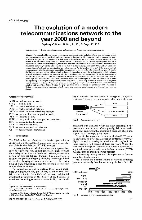
digital network. The time frame for this type of changeoveris at least 15 years, but unfortunately this time scale is not
commontransmission
private networks
Fig. 1 Present layered network
consistent with demands which are now occurring in themarket for new services. Consequently, BT must makeadditional and substantial investment decisions above andbeyond those of simply going digital.
Of particular importance is how much should BT investin new network layers such as packet switching or privatedigital networks; bearing in mind that the payback forthese networks will require at least five years. When thenext major change will occur is also a crucial question, asany totally new public switched telephone network (PSTN)might absorb all existing network services.
In answering these questions it is important to demon-strate how timely they are.
Fig. 2 shows the historic lifetime of various switchingsystems sequentially from bottom to top, for both the USA
and the UK. It is clear that life cycles are quite definitelyshortening; and, taking into account the time to developa new system, then this is now probably the time to thinkseriously about a new generation of switching and net-working architecture beyond the present digital system.
This implies replacing the new digital PSTN with yetanother entirely new network and at the same timeembracing the layers above it.
It can be shown that there are other likely ways aheadand that a rather more evolutionary process will prevailwhich will permit BT to be responsive to market require-ments.
To see how such an evolution might proceed, it will benecessary to consider the following factors:
(a) the present situation(b) the national network in terms of:
(i) nature of physical plant(ii) investment
(c) the role of 64 kbit/s digital networking to 1995 andthe role of ISDN which is part of the 64 kbit/s network
(d) the technology changes which will take place, andtheir effect on costs and trends
(c) market analysis for voice, data and video require-ments
(/) what communications theory offers as guidance(i) traffic theory of VBR systems
(ii) network delay tolerances(iii) traffic handling efficiency
The conclusions to be reached from considering thesepoints can show a possible way ahead.
2 Today's network
The present network consists mainly of analogue transmis-sion with analogue circuit switching.
Tables 1 and 2 show the make up of our present3.4 kHz network and demonstrate the dominant position
Table 1 : The present network
Transmission Capacity
coaxial analogue 70%analogue & digital
Trunk microwave radioanalogue & digitaloptical fibre digital 30%digital
symmetric pair localanalogue & digital analogue 100%
Local digital < 1 %symmetric pair junctionwith screen analogue 94%digital digital 6%
Table 2: The present network
Switching Connections
StrowgerTrunk cross bar
digital
Strowgercross bar
Local TXEdigital
72%28%
< 1 %
59%9%
3 1 %< 1 %
held by Strowger switching equipment. To date, thechanges in technology which have taken place in switch-ing, Strowger to crossbar to reed relay, have simplyimproved 3.4 kHz switching in terms of cost, quality,accommodation, maintenance and administration.
Digital switching as the Table shows is still in itsinfancy at this point in time.
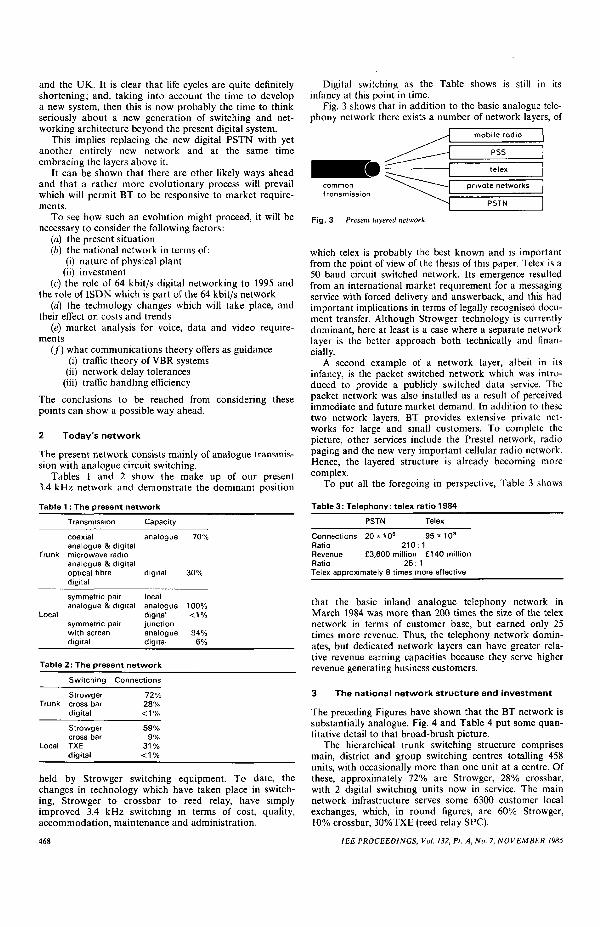
Fig. 3 shows that in addition to the basic analogue tele-phony network there exists a number of network layers, of
commontransmission
mobile radio
PSS
private networks
Fig. 3 Present layered network
which telex is probably the best known and is importantfrom the point of view of the thesis of this paper. Telex is a50 baud circuit switched network. Its emergence resultedfrom an international market requirement for a messagingservice with forced delivery and answerback, and this hadimportant implications in terms of legally recognised docu-ment transfer. Although Strowger technology is currentlydominant, here at least is a case where a separate networklayer is the better approach both technically and finan-cially.
A second example of a network layer, albeit in itsinfancy, is the packet switched network which was intro-duced to provide a publicly switched data service. Thepacket network was also installed as a result of perceivedimmediate and future market demand. In addition to thesetwo network layers, BT provides extensive private net-works for large and small customers. To complete thepicture, other services include the Prestel network, radiopaging and the new very important cellular radio network.Hence, the layered structure is already becoming morecomplex.
To put all the foregoing in perspective, Table 3 shows
Table 3: Telephony: telex ratio 1984
PSTN Telex
Connections 2 0 * 1 0 6 9 5 * 1 0 3
Ratio 210:1Revenue £3,600 million £140 millionRatio 25:1Telex approximately 8 times more effective
that the basic inland analogue telephony network inMarch 1984 was more than 200 times the size of the telexnetwork in terms of customer base, but earned only 25times more revenue. Thus, the telephony network domin-ates, but dedicated network layers can have greater rela-tive revenue earning capacities because they serve higherrevenue generating business customers.
3 The national network structure and investment
The preceding Figures have shown that the BT network issubstantially analogue. Fig. 4 and Table 4 put some quan-titative detail to that broad-brush picture.
The hierarchical trunk switching structure comprisesmain, district and group switching centres totalling 458units, with occasionally more than one unit at a centre. Ofthese, approximately 72% are Strowger, 28% crossbar,with 2 digital switching units now in service. The mainnetwork infrastructure serves some 6300 customer localexchanges, which, in round figures, are 60% Strowger,10% crossbar, 30%TXE (reed relay SPC).
468 1EE PROCEEDINGS, Vol. 132, Pt. A, No. 7, NOVEMBER 1985
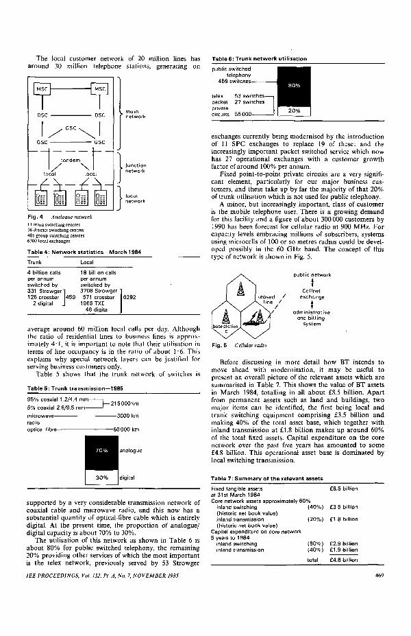
The local customer network of 20 million lines hasaround 30 million telephone stations, generating on
Table 6: Trunk network ut i l isation
Fig. 4 Analogue network11 main switching centres36 district switching centres405 group switching centres6300 local exchanges
average around 60 million local calls per day. Althoughthe ratio of residential lines to business lines is approx-imately 4:1, it is important to note that their utilisation interms of line occupancy is in the ratio of about 1:6. Thisexplains why special network layers can be justified forserving business customers only.
Table 5 shows that the trunk network of switches is
Table 5: Trunk transmission—1985
95% coaxial 1.2/4.4 mm-
5% coaxial 2.6/9.5 mm-
microwaveradiooptical fibre
analogue
digital
supported by a very considerable transmission network ofcoaxial cable and microwave radio, and this now has asubstantial quantity of optical-fibre cable which is entirelydigital. At the present time, the proportion of analogue/digital capacity is about 70% to 30%.
The utilisation of this network as shown in Table 6 isabout 80% for public switched telephony, the remaining20% providing other services of which the most importantis the telex network, previously served by 53 Strowger
1EE PROCEEDINGS, Vol. 132, Pt. A, No. 7, NOVEMBER 1985
exchanges currently being modernised by the introductionof 11 SPC exchanges to replace 19 of these: and theincreasingly important packet switched service which nowhas 27 operational exchanges with a customer growthfactor of around 100% per annum.
Fixed point-to-point private circuits are a very signifi-cant element, particularly for our major business cus-tomers, and these take up by far the majority of that 20%of trunk utilisation which is not used for public telephony.
A minor, but increasingly important, class of customeris the mobile telephone user. There is a growing demandfor this facility and a figure of about 300000 customers by1990 has been forecast for cellular radio at 900 MHz. Forcapacity levels embracing millions of subscribers, systemsusing microcells of 100 or so metres radius could be devel-oped possibly in the 60 GHz band. The concept of thistype of network is shown in Fig. 5.
public network
Cellnetexchange
tadministrative
and billingsystem
Fig. 5 Cellular radio
Before discussing in more detail how BT intends tomove ahead with modernisation, it may be useful topresent an overall picture of the relevant assets which aresummarised in Table 7. This shows the value of BT assetsin March 1984, totalling in all about £8.5 billion. Apartfrom permanent assets such as land and buildings, twomajor items can be identified, the first being local andtrunk switching equipment comprising £3.5 billion andmaking 40% of the total asset base, which together withinland transmission at £1.8 billion makes up around 60%of the total fixed assets. Capital expenditure on the corenetwork over the past five years has amounted to some£4.8 billion. This operational asset base is dominated bylocal switching transmission.
Table 7: Summary of the relevant assets
Fixed tangible assets £8.5 billionat 31st March 1984Core network assets approximately 60%
inland switching (40%) £3.5 billion(historic net book value)inland transmission (20%) £1.8 billion(historic net book value)
Capital expenditure on core network5 years to 1984
We then ask the question as to why the present ana-logue network is shifting so rapidly from analogue todigital. The major factors for the UK are:
(a) economics—strongly in favour of digital switchingand transmission
(b) new services—more easily introduced in digital net-works
(c) technology—with costs continuing to decrease in anever increasingly digital world
(d) network management—more readily implemented ina digital world.
Hence we are completely changing the totally dominantPSTN layer of our layered network from analogue todigital.
A fair analogy is to think of this existing, predominantlyanalogue network as a great mammoth which has to betransformed into a dynamic digital elephant. Such a pieceof genetic engineering is both very costly, and like evolu-tion takes a long time, particularly when it is employingentirely new technology.
4 The role of 64 kbit/s digital networking to 1995
If we look at the first stages of the evolutionary processfrom now until 1995, conversion of the analogue trunknetwork to digital is planned for completion by 1990, cre-ating an entirely new digital switching hierarchy for themain network as shown in Fig. 6 and Table 8.
54 DMSUs
Fig. 6 Digital switching hierarchy
Table 8: Trunk network modernisation
All digital by 1990
transmission
optical
coaxial
microwaveradio
switching 54 digital main switching units0.5 million erlangs
A substantial start has already been made by convertingpart of the present coaxial cable network from analogue todigital working and by introducing digital microwaveradio at 11 GHz. More importantly, there is a substantialprogramme of installation of optical fibre, now establishedin a standard format of 140 Mbit/s monomode transmis-sion with regenerators at nominal 30 km intervals. Oncompletion of the transmission modernisation programmethe network will be approximately 50% optical fibre, 30%coaxial cable and 20% microwave radio.
470
At the same time, the existing main network switchingunits will be progressively replaced by 54 digital mainswitching units, with the role of the present group switch-ing centre being replaced by digital principal localexchanges.
The realisation of an all-digital main network is the keyto the introduction of digital local exchanges (DLE) whichwill offer the customer a much wider range of services thanhas previously been possible.
DLEs are now being installed at a number of key loca-tions, but the immediate need is to offer digital facilities toas many business customers as possible and as rapidly aspossible.
Turning now to the local network: within the plannedinvestment programme for the period 1985 to 1990, it isenvisaged that by 1990 most of the existing GSCs will havebeen closed and that there will be about 10-million digitalexchange lines. Phasing out of Strowger exchanges (S x S)will still leave the TXE family of analogue reed relayswitches as an important element of the local networkbeyond 1990, and we can remedy this problem by theintroduction of digital services in an overlay fashion to asmany locations as possible, by progressively adding smalldigital units to existing exchanges as shown in Figs. 7and 8.
Fig. 7 Development of the Elstree Exchange 1986
TXE
TXD
business
business
residential
Fig. 8 Development of the Elstree Exchange 1990
This may be regarded as an evolutionary way ahead forintroducing local digital services while leaving the mainanalogue switch in place, and should be borne in mind asthe theme evolves.
Figs. 9 and 10 outline the concept of an integrated ser-vices digital network (ISDN); that is one in which thedelivery of a range of digital customer services is madepossible by the introduction of the local digital switchesbut augmented by local digital transmission, thus deliv-ering digital services right down to the customers premises.
The customer part of this scheme is integrated digital
IEE PROCEEDINGS, Vol. 132, Pt. A, No. 7, NOVEMBER 1985
access (IDA), which provides the necessary digital accessfrom the customer premises to the System X digital switch.
terminalsLANsPABXs
80 kbit/s(existing pair)
2 Mbit/s(transverse screen)
PSS
circuit switched(64k bit/s)
signalling
Fig. 9 Integrated digital access to circuit and packet switched networklayers
2 channels 80 kbit/s
3 channels 144 kbit/s
30 channels 2 Mbit/s
Fig. 10 Integrated digital access to the ISDN
ISDN is the only truly digital manifestation, other thanprivate circuits, which the customer perceives from all ofthis investment in digital modernisation. Thus we mayhave 10 million digitally switched local lines in 1990, butaccess, apart from ISDN, will still be analogue. Around1995 we expect the cost of digital access to start approach-ing that of analogue.
Thus with ISDN we have the essentials of a first multi-service network, offering 64 kbit/s speech, 64 kbit/s data,16 kbit/s to PSS, but hindered by the inability of the localdigital switch to offer other than 64 kbit/s paths throughthe switch. Multiples of 64 kbit/s can be achieved, butthese are not contiguous time slots and may well have dif-fering delays, leading to problems in the provision ofswitched services such as sound programme and videowhich demand n x 64 kbit/s.
A further problem lies in the heavy demands put on thedigital switch processor for very short duration calls, forexample electronic funds transfer, and this again empha-sises that the present modernisation plans have beenlargely constructed against a telephony background withother network layers being left to carry those services thatare not so well suited to the fixed bit rate architecture ofconventional digital switching.
Nevertheless, BT like all other administrations is nowheavily committed to this investment programme which isshown in Table 9. For some 15 years at least we shall see abasic 64 kbit/s switched telephony network fed mainly bylocal analogue transmission plant with fully digital ISDNserving the business community. The business communitywill also be served, of course, by all digital private circuitsand PSS. It is important to note that this aspect of BT's
total annual investment will amount to almost £1 billionper year for the next five years.
This leads to continuation of our layered networkarchitecture as shown in Fig. 11, comprised of an infra-structure of digital switching and transmission with
digital transmission(bearer) network
Fig. 11 Layered network utilising digital trunk and local transmissionnetworkRSN = radio services networkSWN = switched wideband networkDSN = derived services networkPSN = packet switched networkTN = telex networkPCN = private circuit networkISDN = integrated services digital networkPSTN = public switched telephone network
network layers providing a crucial supporting role andnow again more complex than before. By 1995, data andtext will be carried by at least four of these layers, namely,telex, PSS, ISDN and private networks. The new layersadded since 1985 are ISDN, automatic freephone andswitched wideband. The reason for the latter is still to bediscussed.
5 The influence of technology
The technology of the next ten years which critically affectscosts in communications systems can be broken down intofive key areas. These are semiconductor technology, inter-connect systems, switching hardware, software systemswith software design and optical technology.
Most people are already familiar with progress in semi-conductor technology, but, as a reminder, the top line ofFig. 12 shows the increase in devices per chip for memory
isC Q.
AM RAM
1M RAM
256k RAM
64k RAM
IEE PROCEEDINGS, Vol. 132, Pt. A, No. 7, NOVEMBER 1985
1975 1980 1985 1990 1995Fig. 12 SI technology evolution to 1995—standard and custom circuits
a 150 k digital signal processor d FAD (UK 5000)b Single-chip data modern e PO codecc Auto design & test CMOS gate arrays
circuits, along with the economic commercial lifetime foreach device. Of more importance perhaps is the bottomline showing telecommunications industry specific devices,doubling at less than the 1.5 years for memory chips, but,nevertheless, continually increasing in complexity. Thisincrease is expected to continue as semiconductor manu-facturers take advantage of the growing size of the interna-tional digital communications market.
The increased complexity of both memory devices andlogic gates for industry's specific devices is of interest, notonly as a means of shrinking equipment but also towards
471
reduction of cost per erlang switched and for the provisionof intelligence embedded in the network. The trend shownin Fig. 13, for the cost per bit for memory devices, is clear
Q. £ i o 2
8 s io°
01970 1980 1990 2000
Fig. 13 Cost trends for silicon ICs—dynamic random access memories
for the future and is borne out dramatically by the limitedcommercial life of each generation of memory device.
Likewise interconnect technology is now progressingafter a fairly stable period (Table 10). At present, the area
Table 10: Interconnect technology progress
wafer-size systems
multilayer ceramic
surface mounting
dual-inline
of silicon on a PCB board, as a fraction of board area, isabout 1 in 1-2000. This will improve significantly over thenext five years with the introduction of surface-mountedtechnology, in which the elimination of pins allows denserpacking by a factor of four.
Further improvements beyond this are already avail-able via multilayer ceramic substrates, which could take upto 300 complex ICs on an area of 30 cm2. Finally, systemson a silicon wafer must surely evolve as self-testing andself-healing circuits are developed further.
The consequences of both of these technologies onswitching equipment are also clear; bearing in mindcurrent production equipment is using technology whichwas state of the art about 5 or 6 years ago.
In Figs. 14 and 15 we can see, for example, a 15000 linelocal switch reducing from 15 to 3 racks by moving fromthe old technology to today's technology, plus the numberof PCBs reducing from 2800 to 600; noting that this doesnot include the customer line interface units.
Extrapolating to 1995 technology in Fig. 16, the sameexchange reduces to 2 PCBs, using \ million gate pro-cessing chips and 4 Mbit/s memories. In actual fact we
memory 10000 chips (20 k bits/chip)Bubble memory: 180 MbitPackage: 161eadDIL
expect to see, say, 3 racks of exchange containing muchgreater intelligence including speech recognition and syn-thesis, multi-service switching providing transparent access
memory 5000 chips (40 k bit/chip)Bubble memory: 180 MbitPackage: 28 lead DIL
Fig. 16 1995 technology
PCBs: 2ICs: logic 20 chips (500 k gates/chip)
memory 100 chips (4 Mbit/chip)Package: 100+ pad chip carrier
15000linelocalswitchcurrent design
to telex, PSS, ISDN etc., with protocol conversion anddatabase access provided on demand. This trend is alreadybeing established in packet switched networks. Digitalcircuit switched networks should follow suit.
The scene for progress in software development is notquite as rosy as that for hardware. For example, the devel-opment costs of a PABX as a function of the end switchcost is about 40% and approximately 60% of that 40% isrequired for generating software.
The cost of writing this software has only halved in thepast decade and this has been due mainly to the elimi-nation of errors during code generation. The cost of errorcorrection is clearly demonstrated in Table 11 which
shows the relative cost to correct a defect at various stagesof development.
Over the next 10 years, i.e. to 1995, the cost is expectedto halve only once again, though many new tools are nowbecoming available to systems designers; all are important,but perhaps the most significant are:
(a) Integration of product management and systemdesign tools, i.e. IPSE
(b) Greater use of automatic high-level-language codegenerators from graphical design descriptions
(c) Introduction of more mathematically formal designmethods
(d) Automation of the design process(e) The integration of hardware and software CAD
facilities (3-5 years)(/) The application of AI technology to system design.
The problem quite clearly is that systems are becomingincreasingly complex and that the new intelligent services,which will be required in the next 10 years, will continue toincrease the development cost of new switching systemsdespite these new software development aids.
472 IEE PROCEEDINGS, Vol. 132, Pt. A, No. 7, NOVEMBER 1985
In providing a digital transmission infrastructureoptical fibre development is expected to continue as shownin Table 12.
Table 12: Trends in optical technology
Bit rate Date
140 Mbit/s now560 Mbit/s 1986/871.2Gbit/s 1989/902.4Gbit/s 1990/91Up to 12x1.2 or 12x2.4 Gbit/s 199410-20 WDM x 2.4 Gbit/s 199530-40 WDM x 2.4 Gbit/s 1995/96
Regenerator spacing = 30 km
At present, 140 Mbit/s monomode is being installedwith regenerator spacings of 30 km. By 1996, 560 Mbit/swill be installed using the same fibre technology by makinguse of improved receiver sensitivity and improved lasersand launching efficiency. This process could well lead to2.4 Gbit/s over current fibre in operational systems by1990. New semiconductor lasers should allow 10-20 wave-length multiplexed channels, each carrying around2.4 Gbit/s, by 1990, while coherent optics will double thatin practical systems in the 1990-95 time scale. Opticaltransmission will dominate the trunk network and there isno end in sight to further development.
Despite these dramatic changes in optical capacity ofsingle fibres and cost trends in silicon integrated circuits,and also enhancements which are emerging in computer-aided-systems design, actual systems costs will not fall asdramatically as hardware costs because the latter formonly a small portion of the total system cost. Savings inhardware will, to some extent, be offset by increases in thecost of installation, in the sophistication of the servicesprovided and development costs, all of which are labourintensive. Nevertheless, costs for local switching and trunktransmission are predicted to reduce by around 50% and75%, respectively, over the next five to ten years as shownin Fig. 17.
0.75
0.25
01984 1985 1986 1987 1989 1990 1991
Fig. 17 Typical cost trends
a Local switchingb Trunk fibre transmission
Despite these projected reductions in the costs of newnetworks, BT's investment plan (Table 9) was around£1 billion per year for the core network over the next fiveyears, and, owing to the reducing costs postulated, willperhaps average £750 million per year for the next tenyears.
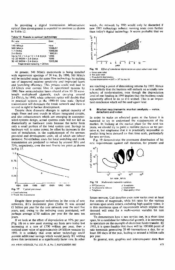
If we look at the effect of depreciation at 10% per year(Fig. 18) on a new asset starting say from zero today butincreasing at a rate of £750 million per year, then aresidual asset value of approximately £4 billion remains by1995. It is unlikely that even newer technology couldprovide additional savings which would justify BT writingdown this investment at a significantly faster rate. In other
1EE PROCEEDINGS, Vol. 132, Pt. A, No. 7, NOVEMBER 1985
words, the network by 1995 would only be discarded ifnew 1995 technology reduced running costs even furtherthan today's digital technology. It seems probable that we
8 101 2 3 4 5 6year
Fig. 18 Effect of cumulative depreciation on asset values over time
a Gross asset valueb Net asset valuec Cumulative depreciationAnnual depreciation = £675 x 106 by year 10
are reaching a point of diminishing returns by 1995. Henceit is unlikely that the business will embark on a totally newscheme of modernisation, even though the depreciationlevel of our funding in 1995 implies that the business couldapparently afford to do so if it wished. This is an impor-tant conclusion which will be used again later.
6 Market requirements: market analysis — voice,data/text and video
In order to make an educated guess at the future it isessential to try to understand the requirements of themarket. In looking at the market place for the next tenyears, we should try to paint a realistic picture as we per-ceive it, but emphasise that it is practically impossible topredict long-term demand on that time scale, particularlyfor new services.
Fig. 19 demonstrates the enormous distribution of bitrate requirements against call duration, for present and
future services. Call duration even now varies over at leastfive orders of magnitude, while bit rates for the variousservices span seven orders, excluding high-quality video. Itis this enormous span of requirements which implies thatdemand will exist for a multi-service variable bit ratenetwork.
To demonstrate how a new service can, in a short timespan, be a candidate for substantial growth, it is interestingto speculate on the example of electronic funds transfer. By1995, it is quite feasible that there will be 100000 point ofsale terminals generating 20-40 transactions a day, for atleast 300 days of the year, leading to around a billion callsper year.
In general, text, graphics and intercomputer data flow
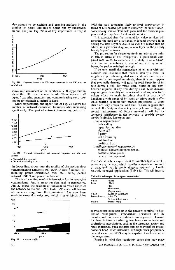
also appear to be exciting and growing markets in thecoming ten years, and this is borne out by substantialmarket analysis. Fig. 20 is of key importance in that it
E 1984 1989year
1994
Fig. 20 Expected increase in VDU-type terminals in the UK over thenext decade
shows our assessment of the number of VDU-type termin-als in the UK over the next decade. These represent alltypes, from telex terminals and communicating word pro-cessors to terminals attached to hosts.
More importantly, the upper line of Fig. 21 shows thenumber of network-connected terminals also increasingsignificantly. The plot of network terminating points, i.e.
1600 k1400 k1200k1000k800k600k400k200k
1984 19941989year
Fig. 21 Network connections and terminals expected over the nextdecade
a Connected data terminalsb Network terminating points
the lower line, shows how the totality of the various datacommunicating networks will grow, to over \ million ter-minating points distributed over the PSTN, packetnetwork, ISDN and private networks.
This is all exciting market information for the nonvoicecommunicator, but, so as to put data back in perspective,Fig. 22 shows the relation of nonvoice to voice usage ofthe network to the mid 1990s. Until 1995 voice will domin-ate network usage and the commitment has now beenmade to carry this voice and switch it at 64 kbit/s. After
100 1
•115
10
5
1984
Fig. 22
474
speech
1989year
Telecom traffic
1994
1995 the only contender likely to rival conversation interms of bits passed per year is currently the infant video-conferencing service. This will grow first for business pur-poses and perhaps later for domestic service.
It is expected that the demand for video services willgenerate the need for a switched wideband network layerduring the next 10 years. And it was for this reason that weadded, in a previous diagram, a new layer to the alreadyheavily layered network.
The projection for electronic funds transfer at the pointof sale, in terms of bits transported, is quite small com-pared with voice. Nevertheless, it is likely to be a signifi-cant revenue contributor to one of our existing servicelayers, the packet switched network.
If we now recall the comparison of bit rate with callduration and also note that there is already a trend forsuppliers to provide integrated voice and data terminals, inother words converged terminals, then it would appearthat eventually demand will exist for total flexibility of bitrate during a call, for voice, data, video or any com-bination required at any time during a call. Such demandrequires great flexibility of the network, and any new tech-nology which we might introduce should be capable ofhandling a wide range of bit rates or mixed mode traffic,while bearing in mind that market projections 10 yearsahead are very unreliable, and that in turn suggests thatnetwork flexibility is also a key to any future strategy. Asecond requirement of future networks will be forincreased intelligence in the network to provide greaterservice flexibility. Examples are:
PSTN requirements:code callingrepeat last numberalarm call3 partycall forwardingautofreefonecredit-card call
There will also be a requirement for another type of intelli-gence in any network which handles a significant amountof data, and that is the intelligence required to handlenetwork managed applications (Table 13). This will involve
Table 13: Managed intelligent networks
VoiceData
VideoEntertainment
Mobile
PSTNISDNPSSKilostreamMegastreamswitched widebandcable TV(BT switched star)cellular radio
providing protocol support in the network terminal to hostsession management, standardised document and filetransfer and convenient database management. Demandfor these facilities is surfacing now from various trade andprofessional associations, such as the insurance, motor andretail industries. Such facilities can be provided on packetbased or SNA based networks, although other proprietarynetworks and the ISDN may be capable of such service inthe longer term.
Bearing in mind that regulatory constraints may place
IEE PROCEEDINGS, Vol. 132, Pi. A, No. 7, NOVEMBER 1985
restrictions on which features can be provided within net-works, what kind of future network can best provide thesemixed services for data, voice and video customer networkmanagement and imbedded intelligence?
Can communications theory help to identify the natureof this new network? As this network is likely to carry amix of services, let us call it an integrated multiservicenetwork.
It must:(a) cater for unknown demands{b) be a very flexible switch(c) be capable of transporting a wide range of bit rates
on demand at any phase of a call.
The question is whether we add another layer to thatshown in Fig. 11 or, alternatively, invent an entirely newnetwork to replace all of this. So far, examination of theproblem has implied that it is unlikely that there will beany commercial sense in replacing, in its entirety, thatmassive new digital PSTN which will still be carryingaround 90% of BT traffic by 1995, and which will have aresidual book value of around £4-5 billion.
7 Communications theory
What is clear is that we do not wish to make, or indeedcannot make, major changes to the new core digitalnetwork every time a new service has to be introduced.Therefore, we need to look at new networks which have ahigh probability of meeting all of the needs of the futureand are, in effect, 'future proof.
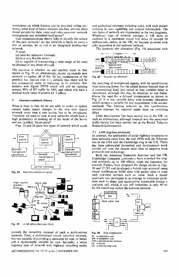
Figs. 23 and 24 show two types of network which could
Fig. 23 Switching multiplexed signals
Fig. 24 A 140 Mbit/sfibre-optic ISLN
provide the versatility required of such a multi-servicenetwork. First, a conventional circuit switched network,but one capable of providing a selectable bit rate, or betterstill a dynamically variable bit rate. Secondly, a serialhighway type of network with highway switching nodes
and packetised messages including voice, with each packetcarrying its own signalling and control information. Thetwo types of network are represented in the two diagrams.Whichever type of network emerges it will have toconform to a maximum round trip delay of around 50milliseconds, unless, in the UK, we become involved withecho supression in our national network.
The dynamic slot allocation (Fig. 25) associated with
\ channeframing Assignmentsignal information
outlet 1 2
Fig. 25 Dynamic slot allocation
the switching of multiplexed signals, with its synchronousfixed duration frame, has the added feature beyond that ofa conventional fixed slot switch in that variable delay isintroduced, although this may be restricted to one frame.Hence the need for a delayed transmission as shown inFig. 23. It is this variable delay with dynamic allocationwhich permits a variable bit rate requirement to be accom-modated. The framing inherent in this synchronousprocess imposes the required upper limit on switchingdelay.
Little development has been carried out in the UK onsuch an architecture, although research into the associatedtraffic theory has been carried out at the British TelecomResearch Laboratories.
7.1 LAN ring/bus protocolsIn contrast, the application of serial highway structures todata networks dates from the mid 1970s with the Ethernetbus in the USA and the Cambridge ring in the UK. Therehas been substantial theoretical and development workcarried out over the decade since then to improve bothprotocols and technology.
Both the American Standards Institute and the UKCambridge Computer Laboratory have extended the orig-inal protocols up to 100 Mbit/s, while the Japanese, forexample Fujitsu, have proposed the design shown in Figs.26 and 27 [1] and developed a hybrid-type protocol usingmixed synchronous TDM slots with packet slots to copewith real-time services such as voice. Such a mixedapproach was developed in an attempt to overcome prob-lems such as delay and maintaining bandwidth during areal-time call, which, if you will remember, is only 50 msfor the round trip within the national network.
LSIL5ILSMX
LS
LSJMX1
LS
fibre optic link SV
NSP
back upi
Fig. 26 Ring configurationSV = supervisory nodeMX = multiplexer nodeNSP = network service processorLS = line setLX = loop exchange node
IEE PROCEEDINGS, Vol. 132, Pi. A, No. 7, NOVEMBER 1985
FH
-TDM slots-
pH
CL
I |
PH
small size
a. 1 1
PH
large size ^—low speed-^|~-high speed—»•—. paths paths
O-X
medium size large size f-—low——|—medium—^speed speed
paths paths
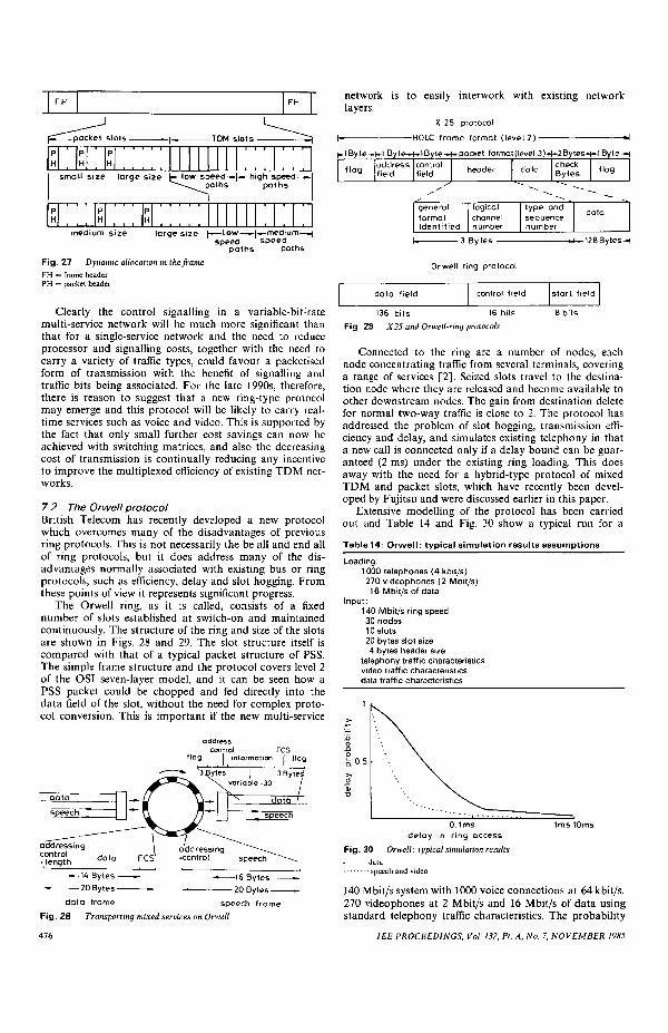
Fig. 27 Dynamic allocation in the frameFH = frame headerPH = packet header
Clearly the control signalling in a variable-bit:ratemulti-service network will be much more significant thanthat for a single-service network and the need to reduceprocessor and signalling costs, together with the need tocarry a variety of traffic types, could favour a packetisedform of transmission with the benefit of signalling andtraffic bits being associated. For the late 1990s, therefore,there is reason to suggest that a new ring-type protocolmay emerge and this protocol will be likely to carry real-time services such as voice and video. This is supported bythe fact that only small further cost savings can now beachieved with switching matrices, and also the decreasingcost of transmission is continually reducing any incentiveto improve the multiplexed efficiency of existing TDM net-works.
7.2 The Orwell protocolBritish Telecom has recently developed a new protocolwhich overcomes many of the disadvantages of previousring protocols. This is not necessarily the be all and end allof ring protocols, but it does address many of the dis-advantages normally associated with existing bus or ringprotocols, such as efficiency, delay and slot hogging. Fromthese points of view it represents significant progress.
The Orwell ring, as it is called, consists of a fixednumber of slots established at switch-on and maintainedcontinuously. The structure of the ring and size of the slotsare shown in Figs. 28 and 29. The slot structure itself iscompared with that of a typical packet structure of PSS.The simple frame structure and the protocol covers level 2of the OSI seven-layer model, and it can be seen how aPSS packet could be chopped and fed directly into thedata field of the slot, without the need for complex proto-col conversion. This is important if the new multi-service
addresscontrol FCS
flag | information | Hag
speech frameFig. 28 Transporting mixed services on Orwell
476
network is to easily interwork with existing networklayers.
X 25 protocol
HOLC frame format (level 2) »
flag addressfield
controlfield header data
checkBytes flag
generalformatidentified
logicalchannelnumber
type andsequencenumber
data
-3 Bytes 128Bytes-H
Orwell ring protocol
data field control field start field
136 bits 16 bitsFig. 29 X25 and Orwell-ring protocols
8 bits
Connected to the ring are a number of nodes, eachnode concentrating traffic from several terminals, coveringa range of services [2]. Seized slots travel to the destina-tion node where they are released and become available toother downstream nodes. The gain from destination deletefor normal two-way traffic is close to 2. The protocol hasaddressed the problem of slot hogging, transmission effi-ciency and delay, and simulates existing telephony in thata new call is connected only if a delay bound can be guar-anteed (2 ms) under the existing ring loading. This doesaway with the need for a hybrid-type protocol of mixedTDM and packet slots, which have recently been devel-oped by Fujitsu and were discussed earlier in this paper.
Extensive modelling of the protocol has been carriedout and Table 14 and Fig. 30 show a typical run for a
Fig. 30 Orwell: typical simulation resultsdataspeech and video
140 Mbit/s system with 1000 voice connections at 64 kbit/s.270 videophones at 2 Mbit/s and 16 Mbit/s of data usingstandard telephony traffic characteristics. The probability
IEE PROCEEDINGS, Vol. 132, Pt. A, No. 7, NOVEMBER 1985
of being delayed by the packetising process and transmis-sion has been calculated and is shown to be acceptable forreal-time services.
The performance of this new protocol has been com-pared using the same modelling techniques with the Cam-bridge ring and token passing protocol. The results in Fig.31 show how the Orwell protocol has successfully over-come some of the disadvantages of these earlier protocols
100"/,
50V.
1 10 100 1000ring bit rate. Mbit Is
Fig. 31 Bandwidth utilisation of ring protocols
a Orwell (slotted)b Token passingc Cambridge BS 6531 (slotted)
in that efficiency of operation is high and does notdecrease at higher bit rates.
We therefore now appear to have a protocol whichcould at least be built on and which can act as the basisfor a multi-service network layer for the 1990s, which cancarry real-time services as well as any mix of text or data.
8 Layered networks 1985-2000
It should now be clear that the present modernisation, inthe form of the current analogue/digital conversion, wasdriven by the incentive to reduce costs and that this wouldbe achieved rapidly and optimally by the sequential con-version of the trunk network followed by the localnetwork. It is true that, as a by product, new services willbe introduced and the quality of service will certainly beimproved, but the new services and even the ISDN, whichhas been regarded as the flagship service of the new alldigital network, did not really stem from direct marketpressures. Indeed, we have yet to determine how themarket will respond to ISDN.
In contrast we have seen that the business sector willexert pressure for new services in the next 5-10 years. Thismeans that the demand for further innovation will comefrom the perimeter of the network, mainly business prem-ises and private networks, communities of business usersand campus type operations. Our present demand fordigital private circuits supports this conclusion. We might,therefore, predict a reversal of the current process of mod-ernisation, which is trunk followed by local, to a newnetwork and service, introduced first at the local level,accompanied by whatever minimal new trunk intercon-nection is necessary. The proposed scheme, as a hypothesisfor the period 1985 to 2000, follows that path.
The equipment which will drive this new processforward is the PABX. This conclusion, as I mentionedearlier, is borne out by the current initiatives by businessto move from analogue widebands serving analoguePABXs to Megastream 2Mbit/s connections to theirdigital PABXs. The integration of voice and data is takingplace now and will be complete in 4th-generation PABXs.
In the medium term, therefore, around 1990, we shouldsee a move from the present layered networks of BT with
individual or direct access on a one to one basis, as shownin Fig. 32, to a layered BT network but now accessed via aunified common access point at the PABX, in accord withFig. 33. The reversal of the present process of modernisa-tion has therefore already started in the business
Fig. 32 Today's servicesRSNSWNDSNPSNTNPCNISDNPSTN
customer
and networks= radio services network= switched wideband network= derived services network= packet switched network= telex network= private circuit network= integrated serfices digital network= public switched telephone network
environment, and a drive for new facilities is emerging nowat the perimeter of the network via new PABX architec-tures.
A fully integrated private network will provide data ser-vices dominantly by X21, X25 or SNA.
A possible 4th-generation PABX architecture, forexample, could access data service by X21 and X25 withprotocol support for other proprietary architectures. Apossible approach could be a composite bus partitionedinto a TDM structure and packet type channels. This isalready beginning to move towards the composite serial-type protocol developed by the Japanese Fujitsu for ahigh-capacity multi-service optical LAN having a mixedpacket and TDM LAN architecture, as shown again inFig. 34. It is safe to predict that, in the shorter term, themore conventional PABX configuration using 64 kbit/scircuit switching for voice, supplemented by a LAN bus orring will win in the 1985-90 time frame. For 1990-95time frame we may see a transition begin from this type ofPABX to the multi-service LAN. From a commercial sup-pliers point of view, it will be vital to get the sequence rightwith delivery of the appropriate level of integrationrequired by the market place. 1990-95 could become avery interesting period in private communications develop-ment.
1EE PROCEEDINGS, Vol. 132, Pt. A, No. 7, NOVEMBER 1985
pH
PH
PH
small size large size t-- low speed——^~~-~-^Daths
PH
PH
PH
•»-high speed ——paths
medium size large size |— low —— |-^medium—-|speed paths speed paths
Fig. 34 Dynamic allocation in the frameFH = frame headerPH = packet header
It is very likely that the PABX will play a central role inbusiness communications and, with its various servers, willbe able to provide intelligence as well as the basic switch-ing function. Intelligence in this context again means pro-tocol support, network management and applicationssupport such as standard document transfer and databasemanagement. What has been shown here is the synergywhich now has to take place between the PABX and itsintelligence and intelligence which resides in or at the edgeof the national BT network, supplied either by BT or otherapplications providers using BT's OSI networks or pro-prietary networks based, for example, on SNA (Fig. 35).
terminals onsite processing
-onsite comms.-twisted pairs
LANs
multiservice access
I I Icommon intelligent networks: corporate public switchedsoftware OSI leased line networks
I DSMS/SNA networks PSTNgateways v a n services private ISDN
I messaging, databases packet PSS1 networks
Fig. 35 System network architecture
The protocol support and applications support mustsurely serve the customer best if the software and softwaresupport are compatible, allowing the customer to migratehis applications from his private to the public network, asbest suits his needs.
Some might argue that the PABX will perform so manyof the functions which have been described that no furtherdiscussion is needed. The argument is that PABX manu-facturers will seek to overcome, on customer premises, anyshortcomings of the public network and therefore reducethe need and attractiveness of a public multi-servicenetwork. It is possible, however, that there is more tocome.
Let us examine the second and third items in Table 15,which is a layered BT network with common user accesswithin the BT network. We now have to see how we canmove to this public integrated service enhancement withcommon public user access say between 1990-95. As thebook value of our investment in the present digital tech-nology will be around £4 billion by 1995 with investment
Table 15: Options for multiservice networks
Separate networks:— separate access— separate operation
Layered network:— separate networks— common user access
Public integrated services enhancement:— common user access— common multiservice medium
still incomplete, at that time, any new public multi-servicenetwork must surely appear as yet another layer in BT'snetwork to be accessed by the private multi-service accessswitch or by a public or BT access switch located in thedigital local exchange. It would certainly be an advantageif the new multi-service layer was of such an architecturethat it can absorb or at least gradually take over thegrowth from some of the other existing layers such as PSS,telex and wideband, leaving the 64 kbit/s digital corenetwork to carry the voice traffic and some circuitswitched 64 kbit/s data, which, it must be remembered,will still amount to some 90% of the total traffic between1995 and the year 2000.
A possible candidate for this new network is the Orwellprotocol described earlier which can carry real-timeservice, voice and video as well as any type of data. Itwould obviously have to be enhanced to serve the publicnetwork, together with the requirements of single datablock to virtual circuit or datagram capability and theother properties shown in Table 16.
Table 16: Multiservice requirements
^ single data block to virtual circuit capability^ low delay for real time services^ low processing overhead• high throughput and efficiency^ support for intelligent network services
The type of architecture which would provide a multi-service capability in conjunction with a public flexibleaccess switch, which will regard the new architecture as yetanother of many service layers, is shown in Figs. 36 and37. This type of architecture greatly simplifies the presentmixture of cabling systems, distribution frames and
Fig. 36RSNSWNDSNPSNTNPCNISDNPSTN
Multiservice network= radio services network= switched wideband network= derivaed services network= packet switched network= telex network= private circuit network= integrated services digital network= public switched telephone network
IEE PROCEEDINGS, Vol. 132, Pt. A, No. 7, NOVEMBER 1985
switches, and we could imagine a flexible node, serial pro-cessing, with a mixture of voice data and video inputs
flexibleaccessswitching
analoguedigitaloptical
Fig. 37 Local switch architecture
extending from say 1000 telephone extensions plus dataand video to 10000 telephone extensions depending on thebusiness requirements. Again, evolution rather than revol-ution.
There is another reason for feeling comfortable aboutthis evolutionary process which stems from the currentwork being carried out by BT on configurable optical net-works. Beyond about 1995 there is the prospect thatoptical technology could play an increasingly major role inshaping the structure and design of telecommunicationsnetworks. Although optical technology is confined, at themoment, to transmission applications, the advent of thesingle-mode fibre is opening up possibilities for radicallynew networks where higher-order switching and othernetwork functions would also be carried out in the opticaldomain. Thus the single-mode fibre could allow single-mode optical components to fulfil such network functionsas switching and routing by manipulating wavelengthmultiplexed channels [3]. These ideas offer very interestingprospects for future network design, but they are still at anearly, formative stage. A very simple example of an all-optical network, configured as a classical star network isshown in Fig. 38, in which the terminals are interconnected
transparentopticalnode
ring - 2 - 3 -
Fig. 38 Configurable optical network: ring
as an LAN using a ring topology. By simple manipulationof wavelengths, the same physical network can be recon-figured into some other arrangement such as the broadcastnetwork shown in Fig. 39. This can be achieved usingtunable laser sources at transmitting terminals withtunable filters at the receiving terminals or nodes. Thewhole process being controlled by a common optical sig-nalling channel.f
The marrying of multi-service serial protocols, based forexample on slotted rings with configurable wavelengthmultiplexed optical network at the perimeter of the main
•f D.B. Payne et al. to be published.
1EE PROCEEDINGS, Vol. 132, Pi. A, No. 7, NOVEMBER 1985
network, is very appealing indeed, especially if this isthought of as an additional layer to our existing multilayer
transparentopticalnode
IFig. 39 Configurable optical network: broadcast
network. This layer could be introduced in precisely thesame way as the present digital overlay switches now beingbrought into service in many local exchanges.
The overall picture has great appeal as it will be driven,in the first instance, by the private communications sectorduring the transition phase from 1990 to 1995. We will beable to learn from the results achieved in the privatenetwork arena and will be responding to customerdemand rather than applying technology push.
The emergence of such private and public local net-works at the perimeter of the network will obviouslyrequire interconnection at a national level and can readilybe envisaged as a main trunk network overlay, probablyhierarchical, as shown in Fig. 40. We can think of local
K0/565Mbit/s565/1150MbiWs
Fig. 40 Multiservice network
public and private networks connected into territorialrings which, in turn, are connected to a national opticalhighway at between 565 Mbit/s and 2.4 Gbit/s.
Fig. 41 suggests a possible timetable for the evolution of
a Optical MSN overlayb 2nd generation MSN switches with transparent optical capabilitiesc MSN overlayd 1st MSN switches
such an overlay about 1995, for introduction of a multi-service local network first in the private then in the publicsectors, with an embryonic national overlay in place by2000. By that time, the network should be incorporating orat least taking up the growth from some of the existing
479
network layers. By 2005, perhaps sooner, second-generation switches using fully configurable higher-orderoptical switches at flexibility points should be developed,leading to a truly optical multi-service network overlay,albeit still using silicon VLSI for carrying out the basicwork at the nodes associated with processing the multi-service protocol down at the kilobit per second level.
Although this paper has not been entirely speculative, itmay now be prudent to file it away in the archives untilthe year 2000, when we can review how accurate the pre-dictions have been.
9 Acknowledgments
The wide span of the material which has been coveredwould not have been possible without the considerable
input from the staff of the BT Technology Executive; par-ticularly members of the Systems Evolution and StandardsDepartment and the Optical Systems Division whom Iwould like to thank for the help they have given towardsthe preparation of this paper.
Acknowledgment is made to the Managing Director,National Networks, for permission to publish this paper.
10 References
1 KAWASHIMA, MOCHIDA and YATSUBOSHI: 'High-capacitymultipurpose LAN using synchronous fibre-optic 'ring'. Fijitsu Labor-atories Limited, presented at ICC, Amsterdam, 1984.
2 ADAMS, J.L., and FALCONER, R.M.: 'ORWELL: a protocol forcarrying integrated services on a digital communications ring', Elec-tron. Lett., 1984, 20, (23), pp. 970-971
3 STERN, J.R.: 'Optical wideband subscriber loops and local area net-works in the UK'. Proc. IEEE Int. Conf. Commun., 1984,2, pp. 884-887
480 IEE PROCEEDINGS, Vol. 132, Pt. A, No. 7, NOVEMBER 1985