+ All Categories
Home > Documents > The EZRT is a joint department of the Fraunhofer ... · (problems with interpolation in...

The EZRT is a joint department of the Fraunhofer ... · (problems with interpolation in...

Date post: 13-May-2018
Category:
Upload: nguyenkhanh
View: 217 times
Download: 2 times
Share this document with a friend
48
The EZRT is a joint department of the Fraunhofer-Institutes IIS Erlangen and IZFP Saarbrücken/Dresden Dr. Randolf Hanke, Dr. Theobald Fuchs International Workshop on Imaging NDE April 25 – 28, 2007, Kalpakkam, India
Transcript

The EZRT is a joint department of the Fraunhofer-Institutes IIS Erlangen and IZFP Saarbrücken/Dresden

Dr. Randolf Hanke, Dr. Theobald Fuchs

International Workshop on Imaging NDE April 25 – 28, 2007, Kalpakkam, India

25.04. 2007 fus

Seite 2

Fraunhofer EZRT – facts & figures

Principles of Computed Tomography

Computed Tomography for the industry

Tasks and applications today

Challenges for the future

Content

25.04. 2007 fus

Seite 3

MagdeburgDortmund

SchmallenbergAachen

Euskirchen

Darmstadt

JenaChemnitz

Dresden

Itzehoe

Bremen

Hannover

Braunschweig

Kaiserslautern

Freiburg

Würzburg

Holzkirchen

KarlsruheSaarbrücken

Duisburg

Erlangen/Fürth

Pfinztal

St. Ingbert

MünchenFreising

Oberhausen

Stuttgart

GolmBerlin

St. Augustin

Rostock

EZRT - Locations

25.04. 2007 fus

Seite 4

Today:Today:Today:Today:

Locations: Saarbrücken, Erlangen, Fürth, Dresden

Employees: 44 (plus more than 40 part time

scientists and students)

Space: > 2200 m2 labs and offices

Turnover: approx. € 4.6 Mio per annum

Financing: > 80% Projects (industry and public)

< 20% basic funding

Equipment: Currently 14 X-ray machines

Cooperation: Industry, FhG, BAM, PTB, University

EZRT - Facts & Figures

25.04. 2007 fus

Seite 5

“Technicum New Materials”

The Bavarian Secretary of State for Trade and Industry Dr. O. Wiesheu

inaugurates the EZRT on July 4th 2000

EZRT - Location Fürth

25.04. 2007 fus

Seite 6

Set-up of a CT system and scheme of measurement

Principles of Computed Tomography

Source

Cone Beam

Object

Flat Panel Detector

x

y

z

Axis of Rotation

Image Image Image Image reconstruction reconstruction reconstruction reconstruction clusterclusterclustercluster

High speed High speed High speed High speed networknetworknetworknetwork

Data acquisitionData acquisitionData acquisitionData acquisition

25.04. 2007 fus

Seite 7

Volume CT of Large Objects

Tube: Tube: Tube: Tube: 450 kV, 2 kW450 kV, 2 kW450 kV, 2 kW450 kV, 2 kW

Digital Flat Panel Digital Flat Panel Digital Flat Panel Digital Flat Panel with 2048 x 2048 Pixelwith 2048 x 2048 Pixelwith 2048 x 2048 Pixelwith 2048 x 2048 Pixel

(40 cm x 40 cm)(40 cm x 40 cm)(40 cm x 40 cm)(40 cm x 40 cm)

Principles of Computed Tomography

25.04. 2007 fus

Seite 8

X-Ray SystemsComputed TomographyComputed TomographyComputed TomographyComputed Tomography

Object geometry

AxialAxialAxialAxial

2D2D2D2D----LayersLayersLayersLayers

3D3D3D3D----VolumeVolumeVolumeVolume

PlanarPlanarPlanarPlanar

LaminographyLaminographyLaminographyLaminography

Digital Digital Digital Digital TomosynthesisTomosynthesisTomosynthesisTomosynthesis

RadiographyRadiographyRadiographyRadiography

FilmFilmFilmFilm DigitalDigitalDigitalDigital

Image ProcessingImage ProcessingImage ProcessingImage Processing

Status of Computed Tomography

25.04. 2007 fus

Seite 9

Fast and efficient approximation

Algebraic Reconstruction

Exact analytical Methods (Inversion of the Radon transform)

Filtered backprojection (Feldkamp-type algorithm)

Iterative solution of a multi-dimensional under-determined system of equations

3D Fourier-type method (problems with interpolation in frequency-space)

Laminography Approximate method for slice imaging by defocussingcontributions from the object outside the plane of interest

Status of Computed Tomography

Reconstruction Methods

25.04. 2007 fus

Seite 10

Computed Tomography - Laminography

Analogues MethodAnalogues MethodAnalogues MethodAnalogues Method

Focal layer is reconstructedLayers outside the focal plane are blurredAdapted for plane, laminar objects like e.g. Printed Circuit Boards

Rotating SourceRotating SourceRotating SourceRotating Source

Counter rotating DetectorCounter rotating DetectorCounter rotating DetectorCounter rotating Detector

Object in focal planeObject in focal planeObject in focal planeObject in focal planeObjects outside focal planeObjects outside focal planeObjects outside focal planeObjects outside focal plane

System Set UpSystem Set UpSystem Set UpSystem Set Up

Planar CT

25.04. 2007 fus

Seite 11

Inspection of electronic Inspection of electronic Inspection of electronic Inspection of electronic multilayer PCBsmultilayer PCBsmultilayer PCBsmultilayer PCBs8 8 8 8 µµµµm bonding wiresm bonding wiresm bonding wiresm bonding wires

3D - Visualization

Oblique radioscopic view

Different layers byTomosynthesis Method

Computed Tomography - Laminography

25.04. 2007 fus

Seite 12

• Simple backprojection of projection data P into object space leads to smearing of details

• Compensation: convolution with a Point Spread Function (PSF) proportional to ρρρρ

(Lakshminarayanan & Ramachandran 1971)

• Filtering of projection data Pf

• Backprojection of Pf into the volume

Principles of Computed Tomography

Filtered Backprojection

25.04. 2007 fus

Seite 13

Spatial domain Frequency domain

Principles of Computed Tomography

Filtered Backprojection

( ) ( ) ( )

[ ]∫ ∫

+∧

θθπωθ θωωω

,0

sincos2,R

yxi ddefRyxf

( ) ( ) ( )∫⊥

+==θ

θ θθ dttsfsRfsfR ,

f

( )σθf̂f̂

25.04. 2007 fus

Seite 14

Bio Imaging Research

Comet, Feinfocus

GE-IT (FhG)

Hitachi

Phoenix

Procon (FhG)

Scanco

SkyScan

Wälischmiller

Viscom

VJ-Technologies

X-Tec

Yxlon

Industry Microna (FhG)

Shake (FhG)

Werth (FhG)

Zeiss (hwm, FhG)

Typical Performance:Typical Performance:Typical Performance:Typical Performance:

Resolution down to 1 µm

Reconstruction of 20483

volumes

Reconstruction time 3,7 s per 10242 slice (Pentium 3 GHz)

Scan times varying with resolution and object

CTCTCTCT----System System System System RayScanRayScanRayScanRayScan 200 (Hans 200 (Hans 200 (Hans 200 (Hans WWWWäääälischmillerlischmillerlischmillerlischmiller GmbH)GmbH)GmbH)GmbH)

CTCTCTCT----System CTSystem CTSystem CTSystem CT----MINI, MINI, MINI, MINI, ProconProconProconProcon

Status of Computed Tomography

25.04. 2007 fus

Seite 15

Argonne National Lab, Chicago / USA

Bundesanstalt für Materialforschung und –prüfung(BAM, Berlin / Germany)

EMPA, Switzerland

Fraunhofer-Gesellschaft EZRT (Saarbrücken, Fürth)

General Electric Global Research

Lawrence Berkeley National Laboratory, USA

Leti, Grenoble / France

Siemens, Medical Solutions (Germany)

Synchrotron-facilities: Bessy, Anka, DESY, ESRF (G/F)

University Linköping / Sweden

University Saarland, Germany

Research

Status of Computed Tomography

25.04. 2007 fus

Seite 16

system know-how

manipulation

X-ray generation

computer-architecture

X-ray detectors

software

• algorithms

• distributed systems

system design

Automation for industrial Radioscopy and Tomography

EZRT fields of expertise

25.04. 2007 fus

Seite 17

Micro CT for high resolution Volume Tomography on micro systems

Example: plastic micro gear

Macro CT for fast Volume Tomography on lightweight components

Examples: Al wheels, motor blocks, metal foams

EZRT product development and business fields

µµµµ----CTCTCTCT

MakroMakroMakroMakro----CTCTCTCT

25.04. 2007 fus

Seite 18

Bench Top System CT-MINI for fast and high resolution Volume Tomography

EZRT product development and business fields

CT CT CT CT forforforfor thethethethe laboratorylaboratorylaboratorylaboratory

CT for industrial 3DCT for industrial 3DCT for industrial 3DCT for industrial 3D----metrologymetrologymetrologymetrology

Biological sample

nominal / actual geometry comparison

25.04. 2007 fus

Seite 19

– Sub-µ radioscopy and CT

– New applications of automated 2D / 3D Image

processing

– 3D / CAD data fusion

– Industrial process integrated CT: “inline CT”

– High speed radioscopy, dynamic radioscopy

in µs range

– Development centre for non-destructive testing of

new materials in aerospace, funded project by

Bavarian government, 4 years, start April 2005

EZRT research areas today

CT CT CT CT sectionsectionsectionsection of a CFC probeof a CFC probeof a CFC probeof a CFC probe

Structural Structural Structural Structural damage after damage after damage after damage after impactimpactimpactimpact

3D-defect recognition with 100 projections (25 s)

25.04. 2007 fus

Seite 20

Physical effects that cause a degradation of image quality

• Beam-hardening with polychromatic radiation

• Scattered radiation

• scatter processes within the object

• primary radiation scattered within the detector

• Properties of the detection system

• Image Lag

• Degradation

• Pixel defects

• Non-Linearities

Artifacts - Methods for Projection Image Correction

EZRT research areas today

25.04. 2007 fus

Seite 21

Artefacts and Means for Reduction

• Combination of pre- and post-processing steps

• IAR: Iterative, reference-less and multistagecorrection method (right)

• Ring Artefact Suppression (below)

Status of Computed Tomography

25.04. 2007 fus

Seite 22

Artefakt Reduction by Simulation of Scattered Radiation

Projection of a step wedge (Al)

Scattered radiation of the step wedge

Scattered radiation of an Al-block

EZRT research areas today

25.04. 2007 fus

Seite 23

• No quantitative information on defects possible by transmission radioscopy

• 3D CT can provide complex spatial information about a component and contained unwanted elements therein

• Evaluation based on 3D methods is less prone to artifacts than 2D methods

• Fast computers and algorithms allow for pace keeping reconstruction and analysis

• Relatively low resolutions necessary for NDT tasks

Fast Inline 3D Computed TomographyMotivationMotivationMotivationMotivation

Status of Computed Tomography

25.04. 2007 fus

Seite 24

3D-CT and defect recognition, 100 s

Fast Inline 3D Computed Tomography: Fast Inline 3D Computed Tomography: Fast Inline 3D Computed Tomography: Fast Inline 3D Computed Tomography: Results of a fast scanning combined with image processingResults of a fast scanning combined with image processingResults of a fast scanning combined with image processingResults of a fast scanning combined with image processing

3D-CT and defect recognition, 25 s

Status of Computed Tomography

25.04. 2007 fus

Seite 25

Inspection Tasks in the Field of Aerospace

• Highly absorbing materials

• Composites with low contrast

• Very large objects

• High resolutionStabilizer of a Rotor Blade

Turbine Blade

Status of Computed Tomography

25.04. 2007 fus

Seite 26

Challenge Turbine Blades

Combination of highly Combination of highly Combination of highly Combination of highly absorbing material with absorbing material with absorbing material with absorbing material with complex structurecomplex structurecomplex structurecomplex structure

High resolution CT to visualize small boreholes (< 50 µm)

Status of Computed Tomography

25.04. 2007 fus

Seite 27

Composite MaterialComposite MaterialComposite MaterialComposite Material

• Carbon/Glass fiber reinforced plastics

• Complex weaved structures

• Low contrast of embedded materials

Status of Computed Tomography

Challenge Rotor Blades

25.04. 2007 fus

Seite 28

Status of Computed Tomography

Inspection tasks in the field material characterization

3D image processing and evaluation of carbon fiber reinforced plastics (CFC)

25.04. 2007 fus

Seite 29

Inspection tasks in the field of automotive3D Defect Visualization of Wheel Samples

CT Processed SamplesCT Processed SamplesCT Processed SamplesCT Processed Samples

Center Region

Spoke Region

Rim Region

Status of Computed Tomography

25.04. 2007 fus

Seite 30

Inspection tasks in the field of biology

Bug

Lily

Seed of a sugar beet

Trachea of a butterfly cocoon

Status of Computed Tomography

25.04. 2007 fus

Seite 31

Micro Gearbox: 2.8 µm Voxelresolution

1,8 mm

Status of Computed Tomography

lubricating grease

25.04. 2007 fus

Seite 32

Archaeology

Status of Computed Tomography

Reconstruction of a terracotta head made by the African NokcultureBy courtesy of the laboratory Kotalla

3D surface2D slice

25.04. 2007 fus

Seite 33

Paleontology

Status of Computed Tomography

CT reconstruction from about 400 x-ray images of the slab with the hidden Ganoid fishBy courtesy of Dr. Viohl, Eichstätt

25.04. 2007 fus

Seite 34

Microsystems → Nanosystems

Offline CT → Inline CT

Qualitative → Quantitative

Stationary → Mobile

Future Trends in Computed Tomography

NanoNanoNanoNano CTCTCTCT to achieve highest-resolution volume data of nano-systems with voxelsize below 100 nm

Inline CTInline CTInline CTInline CT for fast 3D inspection of light metal parts, scan- and evaluation in less than 25 s

Industrial 3DIndustrial 3DIndustrial 3DIndustrial 3D----MetrologyMetrologyMetrologyMetrology with

Computed Tomography

RobotRobotRobotRobot----CTCTCTCT to inspect very large objects on site by mobile CT

WerthWerthWerthWerthTomoScopeTomoScopeTomoScopeTomoScope

25.04. 2007 fus

Seite 35

Quantitative CT - QCT

Future Trends in Computed Tomography

CT as an instrument to measure a physical property at an arbitrary point in space

Levels of improvement:

- Exact measurement of primary intensity

- Precise linearization of the projection images

- Reduction of scattered radiation: e.g. by a-priori knowledge on the inspected part

- Mulit-material beam-hardening correction

- Dual-energy-methods: two scans with different high-voltage

Dual Energy CT of a cube made of plexiglas and aluminum

25.04. 2007 fus

Seite 36

Challenge Sub-µ CT:The limiting factor is the focal spot size of about 1,3 µm (fwhm)

Measurement with about 2 µm resolution

Biological sample –cocoon of a butterfly

Progress Towards Sub-µm CT

(Dr. N

. Uhlmann, EZRT)

(Dr. N

. Uhlmann, EZRT)

(Dr. N

. Uhlmann, EZRT)

(Dr. N

. Uhlmann, EZRT)

25.04. 2007 fus

Seite 37

Carbon fibre reinforced materials

Progress Towards Sub-µm CT1 mm 1 mm 1 mm 1 mm

(St.

(St.

(St.

(St. S

chl

Schl

Schl

Schl öö öötzer

tzer

tzer

tzer , E

ZRT)

, EZRT)

, EZRT)

, EZRT)

resolution: 2 µm

25.04. 2007 fus

Seite 38

High-resolution CT with grey cast iron

(P. Kr

(P. Kr

(P. Kr

(P. Kr üü üüger, E

ZRT)

ger, E

ZRT)

ger, E

ZRT)

ger, E

ZRT)

Fragment of cast iron with 1 mm size (ca. 2 µm voxel size). The probe contains fiber-like lamella of graphite or cementite

Progress Towards Sub-µm CT

25.04. 2007 fus

Seite 39

High-resolution CT of glass fibers with 850 nm voxel size

Progress Towards Sub-µm CT

25.04. 2007 fus

Seite 40

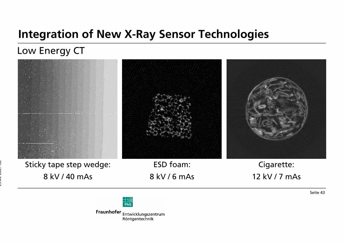
Low energy Low energy Low energy Low energy –––– high high high high contrast measurementscontrast measurementscontrast measurementscontrast measurements

Sensor: MediPix 2X-ray tube: MCB-20 (5 – 20 kV)

Usability: Polystyrene, plastics, organic materials

MediPix 2

Low-energyX-ray tube (focal spot: 3 mm)

He-tunnelRotary disk

The experiments were conducted in collaboration with the Physical Institute IV (University of Erlangen-Nuremberg), Prof. Dr. Gisela Anton

Integration of New X-Ray Sensor Technologies

25.04. 2007 fus

Seite 41

Integration of New X-Ray Sensor Technologies

Direct converting detectorDirect converting detectorDirect converting detectorDirect converting detector

Technical data:

• Sensor material: CdTe• Pixel size: 100 µm x 100 µm• Number of pixels: 252 x 1014• Area: 25.2 x 101.4 mm2

• DQE: > 90% at 60 keV• Energy range: 15 – 300 kV• Frame rate: up to 50 fps

25.04. 2007 fus

Seite 42

Slice of a fiber composite floor cover

Carbon fiber mat at 35 kV

Integration of New X-Ray Sensor Technologies

Low Energy CT

25.04. 2007 fus

Seite 43

ESD foam:

8 kV / 6 mAs

Cigarette:

12 kV / 7 mAs

Sticky tape step wedge:

8 kV / 40 mAs

Integration of New X-Ray Sensor Technologies

Low Energy CT

25.04. 2007 fus

Seite 44

Metrology: Extracting Surface Data

Nominal / A

ctual Value

Comparison

STL Data Surface Visualization

Metrology with Computed Tomography

25.04. 2007 fus

Seite 45

Robot Aided Computed Tomography

Very large objects (e.g. aircraft wings or fins) can be inspected on site by mobile CT

One robot carries the X-ray source, a second one the detector

→ precise positioning and robot communication necessary

Source: Fraunhofer IPA, StuttgartX-ray source

detector

Mobile Computed Tomography

25.04. 2007 fus

Seite 46

Outstanding capabilities of CT in NDT today

1. Material testing

2. Dimensional Measurement

3. Control of integrity and completeness

Fields of progress in the near future

1. Detector systems with higher dynamic, greater area and better efficiency

2. X-ray sources providing higher intensities with small focal spots

3. Algorithms for ROI-reconstructions from a limited number of projections

4. Efficient means to reduce artifacts from beam hardening and scattered radiation

The Future in 3D Industrial Computed Tomography

25.04. 2007 fus

Seite 47

AcknowledgmentAcknowledgmentAcknowledgmentAcknowledgment

Parts of this work was coParts of this work was coParts of this work was coParts of this work was co----financed by the European financed by the European financed by the European financed by the European Union and the Free State Union and the Free State Union and the Free State Union and the Free State of Bavaria of Bavaria of Bavaria of Bavaria

25.04. 2007 fus

Seite 48

Thanks to all people who kindly contributed: Dr. Ulf Haßler, Dr. Michael Maisl, Dr. Thomas Wenzel, Dr. Stefan Kasperl, Steven Oeckl, Ingo Bauscher, Stefan Schlötzer, Stefan Schröpfer, Peter Krüger and Ms. Wutz

Fraunhofer EZRT @ INDE 2007


Recommended