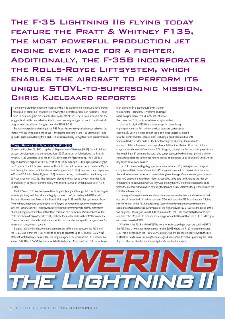
The F-35 Lightning IIs flying today feature the Pratt & Whitney F135, the most powerful production jet engine ever made for a fighter. Additionally, the F-35B incorporates the Rolls-Royce Liftsystem, which enables the aircraft to perform its unique STOVL-to-supersonic mission. Chris Kjelgaard reports P OWERING the Lightning II 10 LOCKHEED MARTIN F-35 LIGHTNING II I n the convoluted development history of the F-35 Lightning II, no issues have drawn more public attention than those involving the aircraft’s propulsion systems. These have been among the most contentious aspects of the F-35’s development, from the long political battle over whether it is to have one engine type or two, to the threat of programme cancellation hanging over the STOVL F-35B. But whatever political challenges the F-35 faces, the technological advances achieved by Pratt & Whitney in developing the F135 – the engine of record for the F-35 Lightning II – and by Rolls-Royce in developing the STOVL F-35B’s extraordinary LiftSystem have been immense. The Pratt & Whitney F135 Chosen on October 26, 2001, by the US Department of Defense (DoD) for a $4 billion system development and demonstration (SDD) contract which decided the Pratt & Whitney F135 would be used for all F-35 development flight-testing, the F135 is a bigger-diameter, higher-airflow derivative of the company’s F119 engine powering the F-22 Raptor. The F135 was chosen for the SDD contract because both Lockheed Martin and Boeing had selected it (in the form of augmented F119s) to power their respective X-35 and X-32 Joint Strike Fighter (JSF) demonstrators, Lockheed Martin winning the JSF contract with its X-35. The Pentagon also found attractive the fact that the F135 shared a high degree of commonality with the F119, two of which power each F-22 Raptor. The F135 and F119 are both axial-fl ow engines (air goes through the core of the engine in a straight line) and they share a “highly common core”, according to Ed O’Donnell, Business Development Director for Pratt & Whitney’s F135 and F119 programmes. From front to back, these two-spool engines are “largely common through the compression system,” says O’Donnell – noting, however, that the commonality is mainly in the form of shared engine architecture rather than common part numbers. Part numbers for the F135 have been designated differently to those for similar parts in the F119 because the US services want to be able to allocate specifi c part numbers to specifi c programmes for inventory-management reasons. Despite their similarities, there are some crucial differences between the F135 and the F119. One is that the F135 needs to be able to generate up to 43,000lb (191.27kN) of thrust ‘wet’ (with afterburner) for the single-engine F-35, whereas the F119 provides a lesser 35,000lb (155.7kN) of thrust with full afterburner. As a result the F135 has a larger inlet diameter (46 inches/1,168mm), larger fan diameter (50 inches/1,270mm) and larger overall engine diameter (51 inches/1,295mm) than does the F119, so it can achieve a higher airflow. Like the F119, the F135 has a three-stage fan (in military- engine parlance, the fan is the entire low-pressure compressor assembly). Each fan stage comprises a one-piece integrally bladed rotor (or ‘blisk’, short for bladed disc) featuring a solid titanium hub with titanium blades welded on to it. The first fan stage has hollow titanium blades and each of the subsequent two stages has solid titanium blades. Aft of the third fan stage the accelerated airflow is split, 57% of it going through the fan duct as bypass air and the remaining 48% entering the core to be compressed, mixed with fuel, ignited and then exhausted as hot gas to turn the turbine stages and produce up to 28,000lb (124.55kn) of dry thrust before afterburner. The F135 has a six-stage high-pressure compressor (HPC) and again each stage is comprises a blisk. Some of the initial HPC stages are made from titanium but because the airflow becomes hotter as it passes through each stage of compression, one or more later HPC stages are made from nickel-based alloy to be able to withstand the high air temperature. In conventional F-35 flight, air exiting the HPC into the combustor is at 28 times the pressure it was when entering the fan and it is at 29 times the pressure when the F-35B is in hover mode. The engine’s single annular combustor features removable liners and a series of fuel nozzles, all housed within a diffuser case. O’Donnell says the F135 combustor is “highly similar” to that in the F119, but features “some improvements to accommodate the appropriate temperature requirements” of the higher-power F135. Overall, the cores of the two engines – the region from HPC to combustor to HPT – are essentially the same size and since the F135 has to produce more dry power at full thrust than the F119 it is likely to run hotter than the F119. While both the F119 and the F135 feature a single-stage high-pressure turbine (HPT), the F135 has a two-stage low-pressure turbine (LPT) where the F119 has a single-stage LPT. This is because, in the F-35B STOVL aircraft, the low-pressure spool to which the LPT is attached has to drive not only the fan stages but also the driveshaft powering the Rolls- Royce LiftFan located behind the cockpit and ahead of the engine.
Transcript
The F-35 Lightning IIs fl ying today feature the Pratt & Whitney F135, the most powerful production jet engine ever made for a fi ghter. Additionally, the F-35B incorporates the Rolls-Royce Liftsystem, which enables the aircraft to perform its unique STOVL-to-supersonic mission. Chris Kjelgaard reports
POWERING PPOWERINGOWERINGthe Lightning II
10 LOCKHEED MARTIN F-35 LIGHTNING II
In the convoluted development history of the F-35 Lightning II, no issues have drawn more public attention than those involving the aircraft’s propulsion systems. These have been among the most contentious aspects of the F-35’s development, from the
long political battle over whether it is to have one engine type or two, to the threat of programme cancellation hanging over the STOVL F-35B.
But whatever political challenges the F-35 faces, the technological advances achieved by Pratt & Whitney in developing the F135 – the engine of record for the F-35 Lightning II – and by Rolls-Royce in developing the STOVL F-35B’s extraordinary LiftSystem have been immense.
The Pratt & Whitney F135Chosen on October 26, 2001, by the US Department of Defense (DoD) for a $4 billion system development and demonstration (SDD) contract which decided the Pratt & Whitney F135 would be used for all F-35 development fl ight-testing, the F135 is a bigger-diameter, higher-airfl ow derivative of the company’s F119 engine powering the F-22 Raptor. The F135 was chosen for the SDD contract because both Lockheed Martin and Boeing had selected it (in the form of augmented F119s) to power their respective X-35 and X-32 Joint Strike Fighter (JSF) demonstrators, Lockheed Martin winning the JSF contract with its X-35. The Pentagon also found attractive the fact that the F135 shared a high degree of commonality with the F119, two of which power each F-22 Raptor.
The F135 and F119 are both axial-fl ow engines (air goes through the core of the engine in a straight line) and they share a “highly common core”, according to Ed O’Donnell, Business Development Director for Pratt & Whitney’s F135 and F119 programmes. From front to back, these two-spool engines are “largely common through the compression system,” says O’Donnell – noting, however, that the commonality is mainly in the fo rm of shared engine architecture rather than common part numbers. Part numbers for the F135 have been designated differently to those for similar parts in the F119 because the US services want to be able to allocate specifi c part numbers to specifi c programmes for inventory-management reasons.
Despite their similarities, there are some crucial differences between the F135 and the F119. One is that the F135 needs to be able to generate up to 43,000lb (191.27kN) of thrust ‘wet’ (with afterburner) for the single-engine F-35, whereas the F119 provides a lesser 35,000lb (155.7kN) of thrust with full afterburner. As a result the F135 has a larger
inlet diameter (46 inches/1,168mm), larger fan diameter (50 inches/1,270mm) and larger overall engine diameter (51 inches/1,295mm) than does the F119, so it can achieve a higher airfl ow.
Like the F119, the F135 has a three-stage fan (in military-engine parlance, the fan is the entire low-pressure compressor assembly). Each fan stage comprises a one-piece integrally bladed rotor (or ‘blisk’, short for bladed disc) featuring a solid titanium hub with titanium blades welded on to it. The fi rst fan stage has hollow titanium blades and each of the subsequent two stages has solid titanium blades. Aft of the third fan stage the accelerated airfl ow is split, 57% of it going through the fan duct as bypass air and the remaining 48% entering the core to be compressed, mixed with fuel, ignited and then exhausted as hot gas to turn the turbine stages and produce up to 28,000lb (124.55kn) of dry thrust before afterburner.
The F135 has a six-stage high-pressure compressor (HPC) and again each stage is comprises a blisk. Some of the initial HPC stages are made from titanium but because the airfl ow becomes hotter as it passes through each stage of compression, one or more later HPC stages are made from nickel-based alloy to be able to withstand the high air temperature. In conventional F-35 fl ight, air exiting the HPC into the combustor is at 28 times the pressure it was when entering the fan and it is at 29 times the pressure when the F-35B is in hover mode.
The engine’s single annular combustor features removable liners and a series of fuel nozzles, all housed within a diffuser case. O’Donnell says the F135 combustor is “highly similar” to that in the F119, but features “some improvements to accommodate the appropriate temperature requirements” of the higher-power F135. Overall, the cores of the two engines – the region from HPC to combustor to HPT – are essentially the same size and since the F135 has to produce more dry power at full thrust than the F119 it is likely to run hotter than the F119.
While both the F119 and the F135 feature a single-stage high-pressure turbine (HPT), the F135 has a two-stage low-pressure turbine (LPT) where the F119 has a single-stage LPT. This is because, in the F-35B STOVL aircraft, the low-pressure spool to which the LPT is attached has to drive not only the fan stages but also the driveshaft powering the Rolls-Royce LiftFan located behind the cockpit and ahead of the engine.
The LiftFan (one of three major components of the Rolls-Royce LiftSystem, which provides the F-35B’s hover capability) is not engaged while in normal forward fl ight and does not feature at all in the F-35A CTOL and F-35C CV conventional take-off and landing variants of the Lightning II. However, from the outset the specifi cation for the F-35’s engine called for “tri-variant compatibility”: the engine powering an F-35A is identical to that powering an F-35B or an F-35C. Nevertheless, the engines are designated differently: the F-35A powerplant is the F135-PW-100; the engine for the F-35C is the F135-PW-400; and the F-35B engine is the F135-PW-600.
Since the F-35B powerplant needs an extra LPT stage to provide the power necessary to turn the driveshaft (which, through a clutch and gearbox, drives the LiftFan), F135s built to power other F-35 variants have the second LPT stage as well. “The engine was designed to support that severe STOVL requirement,” says O’Donnell. For engines powering CTOL F-35As and F-35Cs, the additional turbine stage offers a substantial extra power margin, allowing for potential F-35 weight growth. Since the engine isn’t heavily taxed in many CTOL missions, its maintainability is improved too.
The geometries of the cooling-air paths and airfl ows in the F135’s hot section are different from those in the F119. Turbine-blade coating materials, used to prevent nickel-alloy turbine blades and vanes from melting in the several-thousand-degrees airfl ow coming from the combustor, may well have been updated too. P&W may be able to apply retroactively to production F119s the advances in cooling-path and coating technologies it devised for the F135.
In both engines, cooling air is taken from the bypass airfl ow and by bleeding air away from the HPC stages to cool the HPT and LPT stages, probably by means of air channels etched into their blades and into the turbine casing, as is the case in commercial turbofans. “Even fi fteen-hundred-degree air is cooling air if it’s relative to hotter air,” notes O’Donnell. “The [blade] metal melts at the temperatures we’re operating at and a lot of the technology is in the cooling and coatings.”
Counter-rotating Spools, Ceramics and Augmentors
A potentially important feature of the F135 – but one which Pratt & Whitney doesn’t talk about much – is that the engine’s two spools are counter-rotating, like those in the F119. Since in some cases spool counter-rotation can be used to shape the direction of core airfl ow as it transitions between the HPT and LPT to improve the overall effi ciency of the airfl ow through the engine, this might have allowed P&W to dispense with one or more rows of static stators and vanes in the F135. (Rows of stators and vanes, which are static blades found between
many fan, compressor and turbine stages, act to condition and present the core airfl ow optimally to each subsequent rotating stage.) So P&W possibly has been able to reduce the parts count in the engine and make it somewhat lighter – but it declines to confi rm this.
P&W also won’t confi rm the dry weight of the F135, but a source commenting on an aviation blog cites Warren Boley, President of Pratt & Whitney Military Engines, as saying the F135 weighs 1,500lb (680kg) more than the F119. This would put the F135’s dry weight at around 5,400lb (2,450kg). However, the F135 may have a higher thrust-to-weight ratio than the F119 (the F119’s overall pressure ratio is 26:1 compared with the F135’s 28:1) and so the 5,400lb fi gure might be high. Boley has also suggested the F135 has an uninstalled wet-thrust capability of approximately 51,000lb (226.86kN). If this reads across to an installed basis – in which bleed air and shaft horsepower would be extracted to power aircraft systems – it should provide a comfortable operating margin over the 43,000lb (119.27kN) of wet thrust required by the spec.
The F135 uses ceramic matrix composites (CMCs) in its exhaust nozzle, primarily on the outside sections of the exhaust nozzle on the F135-PW-600 STOVL version of the engine. O’Donnell says that on the STOVL engine, also, some sections of the fan ducts – particularly
TOP: An F135-PW-100 engine undergoing a test run with full afterburner or augmented power generating up to 43,000lb of thrust. PRATT & WHITNEY OPPOSITE: This shot shows an F-35B STOVL F135-PW-600 engine undergoing a test run with full afterburner or augmented power. PRATT & WHITNEY BELOW & LEFT: Cutaway diagrams of the F135 engine. The diagram on the left also shows the LiftFan, gearbox, driveshaft, roll posts and roll ducts components of the Rolls-Royce LiftSystem. PRATT & WHITNEY
at the bottom, “where all the accessories hang on to” – are made from organic matrix composites (OMCs), whereas the fan ducts for the F-35A and F-35C engines are made from titanium. Some of the inlet ducting in the aircraft is also made from OMC material.
According to O’Donnell, P&W has used OMCs in the F-35B to reduce weight by 40 to 50lb (18 to 22.5kg) so that the aircraft can carry a little extra weight – say, an additional 50lb of ordnance – and bring it back if required when the mission calls for the aircraft to land vertically. This “vertical lift bring-back” (VLBB) measurement is a critical performance requirement for the F-35B and while the aircraft as it stands today meets the current spec, the worry is that if the F-35B’s maximum gross weight grows over the course of its operational career (as usually happens with military aircraft), its VLBB performance will need to improve.
Another key feature of the F135 is its augmentor, or afterburner system. While available details of the augmentor are sketchy, the F135 is known to employ multi-zone (probably three-zone) fuel injection aft of the afterburner’s pilot light. These zones inject fuel independently, so that the afterburner does not act in an all-or-nothing way but instead provides a variable range of additional, smoothly transitioning wet thrust at the pilot’s command. Also, like the F119 augmentor, the F135 augmentor is stealthy: The design of the two engines’ augmentors places multi-zone fuel injection into curved vanes which eliminate conventional spray bars and fl ame holders and block the line of sight to the turbine when looking into the engine from behind.
MaintainabilityFrom the outset the F135 has been designed for maintainability, building on the experience Pratt & Whitney gained with the F100 for the F-15 and F-16 and then with the F119 for the
F-22. (When designing the F119, the company brought in US Air Force mechanics to help design its engine-mounted controls and accessories for maintainability). In the F135, all controls affi xed to the casing are ‘single-deep’ – no control units are mounted on top of each other – and the nuts and bolts which attach them to the engine casing are encapsulated in the control assemblies themselves, so nuts and bolts stay with the control units when these are removed. This greatly minimizes the risks of nuts and bolts being lost and causing foreign-object debris (FOD) damage.
Similarly, all engine clamps and blocks stay on the engine casing when an F135 is removed for maintenance and the engine uses no safety wire, eliminating another potential source of FOD damage. All controls and accessories are mounted on the bottom of the engine, making it easier for mechanics to get to them; and these assemblies are modular so that, say, a mechanic could easily remove the electronics or valves or relays for an F135 fuel control unit as entire modules.
O’Donnell says the US Air Force has found the F119 to be “signifi cantly more maintainable” than the earlier F100 – the F119 offers “major orders” of improvement of mean time between failures in terms of maintenance man-hours required – and says P&W expects operators to fi nd the F135 even more easily maintainable and reliable than the F119. Another plus, he says, is that P&W can apply the design-for-maintainability improvements it has developed for the F135 to new F119 production batches as well.
The F135 engine also comes with a digital prognostic and health monitoring (PHM) system and an extensive sensor suite. By means of the sensors, the PHM system constantly monitors the engine’s operating parameters and the condition of its components, and alerts aircraft mechanics if it fi nds anything abnormal. “So a lot less time is devoted to
13LOCKHEED MARTIN F-35 LIGHTNING II
14 LOCKHEED MARTIN F-35 LIGHTNING II
troubleshooting,” says O’Donnell. So seriously did P&W take the job of making the F135 highly maintainable that it tried to design the engine to require only a single hand tool, clamped to the engine when not in use, for all line-maintenance jobs. P&W couldn’t quite achieve that ideal but did succeed to the point where only six hand tools are required.
ProductionHaving obtained initial service release (ISR) certifi cation from the DoD for the CTOL F135 in February 2010 and for the STOVL engine in December, Pratt & Whitney was delivering three production F135s a month by March. Brett Rhodes, P&W’s Production Program Lead for the F135, says the company increased the rate to four a month in April as it completed deliveries under Phase 2 of low rate initial production (LRIP 2) and began delivering engines for aircraft in the LRIP 3 production batch. “That’s a really big achievement – we’re really into the production aspect of delivering production hardware,” says Rhodes. “Lockheed Martin is going to be selling its fi rst CTOL aircraft soon. We started propulsion deliveries a year ago – the engine always has to lead the airplane in the maturity of its development.”
By late March, also, through sub-contractor Rolls-Royce, P&W had completed delivering F-35B variable area vane boxes all the way through LRIP 3 and into LRIP 4. (The variable area vane box [VAVB], which is a critical component in the F-35B’s LiftSystem, actually forms part of the keel of the aircraft and so for any F-35B has to be delivered much earlier than the engine). Additionally, P&W has already delivered F135 inlet debris monitoring systems – the IDMS is a new system which detects debris anywhere in the inlet or engine and alerts the pilot and mechanics – for aircraft well into the LRIP 3 production batch.
Rhodes says that by March 25 P&W had delivered 12 CTOL engines – eight for installation
in aircraft and four as spares – to Lockheed Martin at Fort Worth, as well as six STOVL engines. The company’s target for 2011 is to deliver 40 production F135s, with production from April through December to be split evenly between CTOL and STOVL engines. LRIP 4 deliveries for the F135 itself begin in the fourth quarter and P&W has agreed a deal with the Pentagon to deliver each LRIP 4 engine for 16% less cost than engines under the LRIP 3 cost-plus contract.
At the time of writing, the F135 had fl own in more than 740 F-35 fl ight tests and accumulated more than 1,200 fl ight hours – and a total of more than 21,000 hours of ground and fl ight testing. The F135 and Rolls-Royce LiftSystem had achieved 64 vertical landings by early April and the number should have climbed to well over 70 by this issue’s publication date.
In the DoD’s budget for fi scal 2012, P&W has obtained $1 billion for more engines, fl ight-test support out to October 2016 and component improvements, like those the Pentagon funds under its Component Improvement Program (CIP). The rival GE/Rolls-Royce Fighter Engine team has always said the F135 has durability issues because it essentially uses the core of the smaller F119 and accordingly runs hot. However, Boley describes the $400 million of what he calls “CIP-like” funding in the budget as being for “maintainability, sustainment and affordability” improvements in the mature F135 engine rather than to improve component durability. P&W would introduce such improvements in block upgrades, he says.
“At this point in the development cycle, it’s really maintainability related and for affordability more than durability,” says Boley. “We’d like to get these in as soon as possible to reduce costs … ‘spend a dollar today and save a dollar tomorrow’. Durability improvements take much longer, because you need to design, test and incorporate them.”
Boley says the F-35B’s probationary period will not stop production of the F135-PW-600 STOVL engine after the LRIP 4 production phase, but it means F135 production won’t be increased as originally planned. “Through Lot 4, we’re producing at the same rate,” as previously planned. “Lots 5, 6 and 7 are reduced because that’s the probation.” Previously, the F135 production plan called for equal numbers of STOVL and CTOL engines to be delivered in the LRIP 5 batch, but now CTOL production will overtake STOVL in LRIP 5.
“Net-net, there will be a reduced quantity” of F-35B engines, but “if it gets through the probation, there may be only a reduction of 10 to 12 units,” says Boley. But while P&W will be increasing production to 50-to-80 F135s a year by 2013 or 2014, “We’re not ramping yet to that 125 a year,” originally envisaged for that period.
However, F-35 fl ight-testing has now been extended to October 2016 from 2013 and spare engines will be required for production F-35s as well. Boley says Pratt & Whitney has
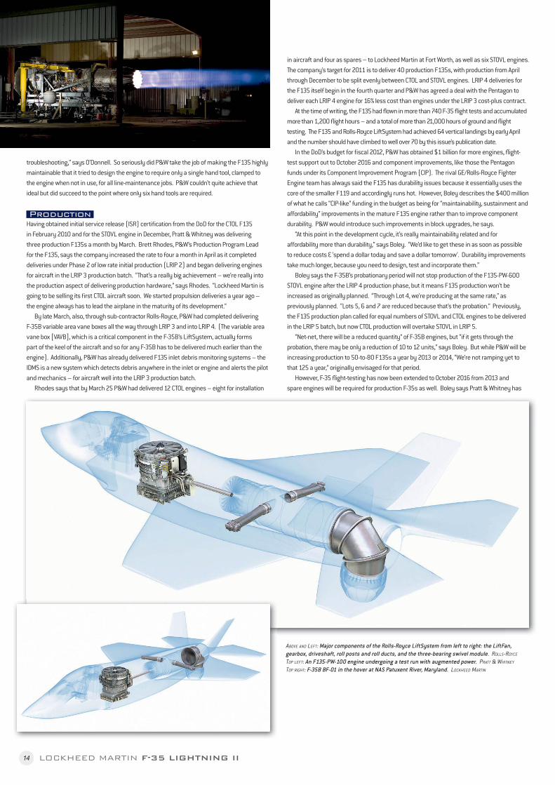
ABOVE AND LEFT: Major components of the Rolls-Royce LiftSystem from left to right: the LiftFan, gearbox, driveshaft, roll posts and roll ducts, and the three-bearing swivel module. ROLLS-ROYCE TOP LEFT: An F135-PW-100 engine undergoing a test run with augmented power. PRATT & WHITNEY TOP RIGHT: F-35B BF-01 in the hover at NAS Patuxent River, Maryland. LOCKHEED MARTIN
15LOCKHEED MARTIN F-35 LIGHTNING II
proposed to the DoD that, “to keep some of the production rate up,” it should be allowed to increase deliveries as much as possible towards the 125-a-year production plan by building more engines as spares than originally planned. “Now we have to do more, because we have to produce more fl ight-test engines. We need to fl y longer.”
The Rolls-Royce LiftSystemOne of the most remarkable features of the F-35 programme is that when the STOVL F-35B is hovering, its propulsion system produces very nearly as much thrust without afterburner as the engine does in forward fl ight with its afterburner fully lit. The F-35B’s engine has to produce 39,400lb (176kN) of vertical thrust without afterburner in hover mode, while in conventional fl ight it produces 28,000lb (124.55kN) of dry thrust and 43,000lb (191.27kN) with full afterburner.
The F135-powered F-35B relies on two systems to achieve the high level of vertical thrust. First is its full authority digital engine control (FADEC) unit – computers made by BAE Systems and attached to the engine, but running on Pratt & Whitney proprietary FADEC software. In hovering fl ight, the FADEC computers make the engine work harder, allowing it to increase dry thrust from 28,000lb to 39,400lb without using afterburner.
Second, the F-35B relies on the Rolls-Royce LiftSystem. This consists of several major components. First is the LiftFan, a horizontally mounted fan unit located behind the F-35’s cockpit. The 50-inch diameter, 50-inch deep (50 inches equates to 1,270mm) LiftFan draws in cold air through an inlet on the top of the fuselage and accelerates it to produce vertical lift. The LiftFan inlet is covered by a large, Lockheed Martin-made door – nicknamed the ’57 Chevy Hood’ – hinged to the structure of the aircraft aft of the LiftFan inlet. The door is only opened when the F-35B is hovering, performing a short take-off or transitioning between horizontal and vertical fl ight.
The LiftFan features two counter-rotating fans, one directly above the other. Each is a blisk, with the upper fan containing 24 hollow titanium blades and the lower fan containing 28 solid titanium blades, according to Gareth Jones, Rolls-Royce’s Chief Engineer for the LiftSystem. Each fan is driven by a separate bevel gear system. (Bevel gears allow torque from a horizontal shaft to be transmitted through 90° to a vertical shaft by means of conical gears.)
Both bevel gears are contained in a common gearbox and are powered by a driveshaft which runs along the F-35B’s longitudinal axis. The driveshaft is powered by the low-pressure spool of the F-35B’s engine, which is located behind the LiftFan. (The LiftFan is located in front of the engine inlet and the driveshaft connecting the LiftFan and the engine runs through the inlet, under a fairing). On the engine, the driveshaft is connected to the fan hub for the engine’s fi rst fan stage, which is driven by the low-pressure spool.
Another major LiftSystem component is the clutch for the LiftFan gearbox. The driveshaft
is always spinning when the engine is lit, but vertical lift from the LiftFan is not always required. When vertical lift is not required – for instance, in conventional fl ight – the clutch is disengaged. It only engages and locks when vertical thrust is commanded. Because of the signifi cant amounts of friction generated and the high temperatures involved, the clutch plates are made from the same hard-wearing material as is used in the carbon brakes of large commercial aircraft such as the A380.
Below the LiftFan, the variable area vane box (VAVB) provides an exit path for the cool air driven downwards vertically by the LiftFan. Rolls-Royce produces the VAVB, which is made of aluminium and contains louvred vane doors. These can be angled all the way from 45° back, through fully vertical to 5° forward to provide variable directionality for the downward cool-air fl ow from the LiftFan, as commanded by the pilot through the aircraft’s FADEC units.
When the F-35B is hovering, the driveshaft delivers 28,000 shaft horsepower to the LiftFan’s clutch-and-bevel-gear system so that the LiftFan provides 20,000lb (124.55kN) of downward thrust as a column of cool air. (In the F-35B’s hover mode the coupled F135-driveshaft arrangement acts exactly like a turboprop engine, except that most of its power output is used to drive air vertically rather than horizontally, so the F135 is actually the world’s
most powerful turboprop engine when installed in the F-35B.)
In hover mode another 15,700lb (69.84kN) of thrust exits the engine exhaust as hot gas and is directed downwards at the rear of the aircraft by the aircraft’s three-bearing swivel module (3BSM). This remarkable piece of equipment
consists of three articulated sections of nozzle casing, each of which is made from titanium. Each section is joined to the other sections by and driven by its own ring bearing. When the F-35B hovers, the FADEC commands the 3BSM – which can direct air through a 95-degree range from 5° forward to horizontally back – to swivel downwards to direct hot engine-exhaust air in the same direction as the direction of the cool air produced by the LiftFan near the front of the aircraft. The 3BSM can swivel fully from horizontal to vertical orientation in 2.5 seconds.
Jones says the ring bearing for the fi rst 3BSM nozzle section is driven by its own actuator, while the bearings for the second and third sections are driven by a common actuator which acts directly on the ring bearing for the second nozzle section and drives the ring bearing for the third section through a travel gearbox. “These [two] sections can’t articulate independently but do so through a fi xed ratio, and they are set to oblique angles to each other,” explains Jones. Both of the ring-bearing actuators for the 3BSM are powered by fueldraulics: some of the aircraft’s fuel is pressurized to 3,500lb per square inch (2.46kg per square millimetre) to act as a hydraulic fl uid to power the 3BSM actuators’ servo-valves.
Other major components of the LiftSystem are the aircraft’s two roll posts and the roll-post ducts which connect them to the engine. Jones says each roll-post duct is a “very
“the engine was designed to support the severe
stovl requirement.”
16 LOCKHEED MARTIN F-35 LIGHTNING II
complex part” whose shape changes from a circular shape at one end – where it connects to the engine – into a toroidal (a surface generated by rotating a closed plane curve about a coplanar line that does not intersect the curve) shape at the other end, where it attaches to the roll post. Each titanium roll-post duct is superplastically formed, diffusion-bonded and laser-welded.
According to Jones, the roll posts themselves are variable-area nozzles which are situated in the lower part of each inner wing section and act to provide roll control for the F-35B while it is in hover mode. In order to do this, the roll-post ducts direct bypass air from the engine to the roll posts, which drive the air out through the bottom of each wing. In the F-35B, 3,700lb (16.46kN) of thrust in the form of bypass air is directed out to the two roll posts while hovering.
Each roll-post assembly features a pair of fl ap-type doors in the bottom of the wing, controlled by the FADEC. Jones says these titanium doors are controlled by rotary actuators which allow fully variable opening, providing a degree of thrust variability and directionality so that the pilot can control roll while hovering. He says Lockheed Martin’s original X-35 concept demonstrator featured doors between the engine casing and the roll-post ducts which could be closed when the aircraft was not hovering, but in production aircraft there are no such doors and bypass airfl ow is constantly sent to the ducts. The only way to control roll-post thrust is via the fl ap-doors in the bottom of the wing.
The demand for very high power during hover requires that the engine receive a high amount of airfl ow, so Lockheed Martin designed the F-35B with a pair of auxiliary air inlet
(AAI) doors in the upper surface of the fuselage behind the big inlet door for the LiftFan. These AAIs provide additional inlet air for the F135 engine, not the LiftFan.
ComplexitiesThe complexity of the F-35B’s propulsion system and the performance requirements demanded of the aircraft by the Pentagon has created issues that have become evident in fl ight-testing. These are among the issues which have delayed the F-35B, led it to running well over-budget and persuaded US Defense Secretary Gates to put the F-35B into a two-year probationary period. However, the three main issues affecting the LiftSystem are all well understood; and long-term fi xes – none involving massive technological challenges – are in development.
Two issues involve parts getting too hot. LiftFan clutch plates have been found to rub together occasionally while the F-35B is in conventional fl ight and plates have been overheating. The plates are cooled by a fan forcing air over them in hover mode but not during conventional fl ight. The fi x is to install a passive air-cooling circuit in the clutch for cooling during conventional fl ight and also to install a sensor to alert the pilot to climb up to 10,000ft (3,048m) if the clutch plates get too hot.
Roll-post actuators have also been burning out faster than anticipated, because of overheating through leakage of hot bypass air as roll-post nozzle seals age. Again, sensors have been installed and in the short term the actuators have been insulated. Jones says a permanent fi x, redesign of the actuators to withstand hotter temperatures, uses proven technology and is well under way. Insulation of the actuators will not form part of the permanent fi x.
The third LiftSystem issue is that build tolerances and engine thermal and pressure growth have caused the driveshaft for the LiftFan to expand and contract to a greater degree longitudinally during operation than Lockheed Martin’s original design requirement intended. In development aircraft, clasp spacers are being used between the driveshaft and the engine’s low-pressure spool to accommodate the extra expansion, but in production aircraft a bellows-type coupling will be affi xed between the driveshaft and the engine fan hub.
ABOVE: The F135 augmentor or afterburner system has ceramic matrix composites in the exhaust nozzle. PAUL RIDGWAY
LEFT: This shot shows the F135’s fi rst fan stage blisk comprising a solid titanium hub and hollow blades. PRATT & WHITNEY