24
The first truly integrated mixed zone control system that communicates directly to the Munchkin Boiler. Heat Transfer Products, Inc. 120 Braley Road East Freetown, MA 02717

The first truly integratedmixed zone control systemthat communicates directlyto the Munchkin Boiler.
Heat Transfer Products, Inc.120 Braley Road
East Freetown, MA 02717

USING THIS MANUAL
2
TABLE OF CONTENTS SECTION 1
General Information Pg. 3
SECTION 2How Vision 2 Works Pg. 3
SECTION 3System Operation Pg. 3
SECTION 4The Vision 2 Control System Features Pg. 4
SECTION 5Installation of Your Vision 2 Pg. 6
SECTION 6Vision 2 Programming Pg. 10
SECTION 7Vision 2 Program Access Pg. 11Piping Diagrams / Electrical Diagrams Pgs. 18–24
DANGER DANGER indicates an imminently hazardoussituation which, if not avoided, will result indeath or serious injury.
B. SPECIAL ATTENTION BOXES Throughout this manual you will see thesespecial attention boxes to the right of this pagewhich are intended to supplement theinstructions and make special notice ofpotential hazards. These categories are asdefined by the ANSI Z535.A Standard.
A. INSTALLATION SEQUENCE Follow the installation instructions provided inthis manual in the order shown. The order ofthese instructions has been set in order toprovide the installer with a logical sequence ofsteps that will minimize potential interferencesand maximize safety during heater installation. WARNING
WARNING indicates a potentially hazardoussituation which, if not avoided, could result indeath or serious injury.
CAUTION CAUTION Indicates a potentially hazardoussituation which, if not avoided, may result inminor or moderate injury.
CAUTIONCAUTION used without the safety alert symbolindicates a potentially hazardous situation which,if not avoided, may result in property damage.
USING THIS MANUAL
GENERAL INFORMATION / HOW VISION 2 WORKS / SYSTEM OPERATION
3
SECTION 1: GENERAL INFORMATION The Vision 2 is the first truly integrated mixed zone control system that communicates directly to theboiler through a three wire bus connection. Each Vision 2 can control up to 4 independent zones. MultipleVision 2 control panels can be connected together to control up to 32 independent zones. Visioncontractors can now use a Munchkin Boiler and seamlessly control individual zones operating at differenttemperatures through the Vision 2 controller. Each zone is controlled through a motorized modulating,three way mixing valve that will control the delivered temperature to the zone and the supply temperaturefrom the connected Munchkin Boiler. If two or more zones are calling for heat at the same time, eachthree way mixing valve will automatically adjust to assure that only the required temperature is deliveredto each zone. This feature allows the Munchkin Boiler to operate at a much higher efficiency when hightemperature zones are required. Only Vision contractors can install the Vision 2 system with the use ofa Vision Pass Code. This gives each customer the assurance that the Vision System will be installedproperly and professionally.
SECTION 2: HOW VISION 2 WORKSThe Vision 2 control uses a three wire bus communication system to control up to 4 independent zonesand controls the operation of the connected Munchkin Boilers. The Vision 2 control will regulate theoperation of each connected three-way mixing valve to assure you that the desired supply temperatureis achieved. Each three way mixing valve will adjust the flow from the primary loop and return water fromthe zone in order to achieve the desired temperature output to the zone. The Vision 2 panel will thencommunicate with the Munchkin Boiler to regulate its output and temperature set point in order to satisfythe needs of the independent zones. Each mixed zone is equipped with a highly accurate strap-on supplytemperature sensor (spring loaded for better surface connection to the pipe) to assure the most accuratetemperature measurement. The supply temperature sensor is installed on the mixed water outletconnection from the three mixing valves and wired back to the Vision 2 panel. The supply temperaturesensor controls the modulation of the mixing valve and the boiler supply temperature to assure anaccurate temperature response to the mixed zone. Each individual mixed zone can supply additionaltraditionally piped zones that all require the same mixed temperature.
Individual zones can be controlled through the use of a thermostat, outdoor sensor, or a 0-10 volt inputfrom a building management system. If an outdoor sensor is used, each independent zone can beprogrammed with a personalized outdoor reset curve.
SECTION 3: SYSTEM OPERATION When the Vision 2 is powered, mixed zone 1 is displayed, which is the supply temperature sensortemperature. If the S3 key is pressed, the next consecutive zone temperature will be displayed. The lastfunction displayed is the temperature measurement in Fahrenheit to Celcius. Vision 2 allows the user tocontrol a zone temperature through either an outdoor reset, 0-10 volt input or a thermostat. Once theVision 2 receives a signal for a call for heat, the Vision 2 panel will start to regulate the supply temperatureby modulating the three way valve to meet the desired supply temperature. Individual outdoor resetcurves can be programmed for each of the four mixed zones to the Vision 2 system. Once the roomthermostat or 0-10 volt signal is sent , the Vision 2 panel will integrate the operation of the MunchkinBoiler with the mixed zones to regulate the input into the system to assure maximum efficiency of yourheating system.
Note: The Vision 2 may be used with Vision 3 when more than one boiler is used for the heating system.

4
SYSTEM OPERATION / INSTALLATION
PARTS INCLUDED IN YOUR VISION 2 SYSTEM
1. Outdoor sensor – (1) piece. (7250P-319) 2. Indirect Sensor – (1) piece (7250P-325)3. Supply Temperature Sensor (7250P-324) Spring loaded for better surface connection to the
pipe) – (1) piece.4. Bus Communication Connection Wire (Line A) - (1) piece.5. Bus Communication Connection Wire (Line B ) - (1) piece.6. Bus Communication Connection Wire (Common) - (1) piece.7. Installation Manual – LP-1188. Warranty – LP-151
PARTS INCLUDED IN VISION 2 MIXED ZONE PACKAGE
1. “Three Way PWM Motorized Zone Valve (CV-8) – (1) piece. (7250P-479)2. Supply Temperature Sensor (7250P-324) Spring loaded for better surface connection to the
pipe) – (1) piece.
SECTION 4: VISION 2 CONTROL SYSTEM FEATURES THERMOSTAT INPUT
Standard Room thermostats can be connected directly to the Vision 2 board to control the operation ofthe mixed zones (Maximum of 4 mixed zones for each Vision 2 Panel).
OUTDOOR SENSOR
The user can install the outdoor sensor directly to Vision 2 board to control the supply temperature tothe mixed zone (a maximum of 4 mixed zones for each Vision 2 Panel). The user can program individ-ual reset curves based on the desired temperature required for that mixed zone.
BUILDING MANAGEMENT SYSTEM 0 TO 10 VOLT SIGNAL FUNCTION
Building Management systems can connect up to the Vision 2 to change the supply temperature for eachmixed zone (a maximum of 4 mixed zones for each Vision 2 Panel). Each mixed zone can be programmedto allow a 10 volt signal to provide the maximum supply water temperature set point value programmedinto the Vision 2 panel. When the voltage signal to the Vision 2 drops to low as 1.5 volts the supply watertemperature will have reached its lowest programmed setting. If the voltage drops below 1.5 volts, thedemand for heat will shut off. To set your design maximum and minimum temperature, you will need tofirst access the Vision 2 program in Section 7.
CAUTION Wiring Connection Specification - Wire 22 AWG Maximum to 100 feet or 18 AWG upto 150 feet. Length of wire cannot exceed 150 feet.

INSTALLATION
5
24 VAC OUTPUT (LIMITED AMPERAGE 1.0 CAPACITY) FUNCTION
The Vision 2 is equipped with a 24 VAC output. This can be used to power additional devices that maybe required in the installation
SUPPLY TEMPERATURE SENSOR
The zone sensor is used to control the heat output from the three-way valve to each mixed zone. The sen-sor provides an accurate temperature measurement to the Vision 2 board. The sensor is connected witha plastic strap to the A-B section of the three-way valve, assuring fast response to temperature changes.The sensor is equipped with a spring to assure a solid bond to the pipe. Once connected, the sensor willprovide a constant temperature feed back to the Vision 2 board. This assures a very controlled temper-ature delivery to each mixed zone.
110 VOLT PRIMARY CIRCULATOR OUTPUT FUNCTION ( LIMITED 6.3 AMPS MAXIMUM)
The Vision 2 can control the operation of each circulator pump connected to the mixed zone. The indi-vidual circulator pump for each mixed zone can be wired directly to the panel. This will supply 110 voltsto the mixed pump. The mixed pump will automatically start when there is a call for heat.
THREE WAY VALVE OUTPUT FUNCTION
The Vision 2 can control the modulation of each three way valve connected to the mixed zone. Eachthree-way valve can be connected directly to the Vision 2 panel. Once connected, the three way valvewill modulate the output to a mixed zone to control the supply water temperature. This assures a veryaccurate temperature delivery to each mixed zone.
Fig. 4-1

INSTALLATION / CONTROL SYSTEM FEATURES
6
THREE WIRE BUS CONNECTION FUNCTION
The three wire bus connection allows the Vision 2 board to communicate directly to the connectedMunchkin Boiler. This bus communication is simple to install. Wires are provided that connect the Vision2 to the Munchkin Boiler. Once connected, the Munchkin will only deliver the required supply tempera-ture to the primary loop based on what the individual mixed zone will require during a call for heat.
VISION 2 DISPLAY PANEL
The Multiple display panel allows the user to monitor and program many functions in the Vision 2 con-troller .The upper portion of the display, with the push button key, allows the user to activate the differ-ent status functions and program the individual mixed zones. The lower section of the multiple displaypanel allows the user to monitor the functions and temperatures for each mixed zone. If the mixed zoneis not being used at the time, the display will read (NC)
VISION 2 WITH VISION 1
The Vision 1 system can be used to provide an additional priority zone for domestic Hot Water (DHW)see drawing V2-1 in piping details). The additional priority zone provided by the Vision I System for DHWwill now shut down the P1 central heating pump and activate the P2 pump for the DHW. This allows theVision Contractor to provide DHW while still maintaining the four mixed zones of the Vision 2 panel.
VISION 2 WITH VISION 3
The Vision 3 system can be connected to the Vision 2 when using multiple Munchkin Boilers. The Vision3 will control the operation of the connected Munchkin based on information provided by the Vision 2Control. The three wire bus communication is the only connection needed between the Vision 2 and theVision 3 Control.
SECTION 5: INSTALLATION OF YOUR VISION 2 MOUNTING THE VISION 2 CONTROLLER
Select a mounting location for the Vision 2 Controller that meets the following criteria: • Close to the Munchkin Boiler• Dry, relatively clean area • Easily accessible for service person • Facilitates wiring of the unit • Mounting surface must be secure. • Location must be within one hundred and fifty feet of all sensors (Outdoor, supply temper-
ature sensor ) Remove the cover of the unit by removing each of the four Philips head screws in each corner of theenclosure. Next, slide the cover straight off of the rear part of the enclosure. Position the unit on themounting surface so that the wiring can be accomplished with a minimal amount of difficulty and theLED indicators on the bottom of the unit can be seen by service personnel. Mark the location of themounting holes on the mounting surface. Remove the unit from the area and drill the appropriate sizepilot hole for the mounting screws.
CAUTION Do not drill through the enclosure into the mounting surface. Doing so may causechips to get into the Vision 2 and permanently damage the unit.

Mount the unit by installing a screw through each of the four holes provided in the rear of the unit. Besure that the unit is securely fastened to the mounting surface.
Replace the cover on the unit after all wiring is complete.
WIRING POWER TO THE UNIT
Refer to Drawing V2/V3-E1 on page 23 for example wiring.
This unit should be supplied with 120 volt power from a branch circuit capable of delivering the neces-sary current for the system. This unit will draw a maximum of 26.2 amperes in operation with amp drawdependent on the horsepower of the motors attached to it (pumps, three-way valves). Before connect-ing the supply to the unit, the total required amperage should be calculated by adding the full load ampererating of all the motors together then adding 1 ampere for the control itself. It is suitable and recom-mended to connect this unit to the same circuit as the Munchkin boiler being controlled as long as thetotal does not exceed that of the supply circuit.
The Vision 2 Controller and the Munchkin Boiler must share the same earth ground to guarantee troublefree communications between the Vision 2 Controller and the Munchkin Boiler. This ground connectionshould be made with minimum of 14 AWG wire connected to terminal C1-6 of the Vision 2 Controller andat least one of the ground wires from the Munchkin Boiler as well as a junction box ground connection.
WIRING OF MIXED ZONE PUMPS
Depending on your installation requirements, mixed zone pumps can be connected directly to the Vision2 Control panel. Listed in the chart below are the Terminal Locations for up to 4 mixed zone pumps.
CONTROL SYSTEM FEATURES
7
WARNING Wiring of this product should only be done by a qualified, licensed electrician inaccordance with all local wiring codes.
CIRCULATOR PUMPSDevice Terminal Description
Pump Mixed Zone 1 C1-9 Hot
C1-10 Neutral
C1-2 Ground (bare or green)
Pump Mixed Zone 2 C1-11 Hot
C1-12 Neutral
C1-3 Ground (bare or green)
Pump Mixed Zone 3 C1-13 Hot
C1-14 Neutral
C1-4 Ground (bare or green)
Pump Mixed Zone 4 C1-15 Hot
C1-16 Neutral
C1-5 Ground (bare or green)

WIRING THE THREE WAY MODULATING VALVE
Depending on your installation requirements, three-way modulating zone valves can be connected direct-ly to the Vision 2 Control. Listed in the chart below are the Terminal Location for up to 4 three-way mod-ulating valves.
WIRING OF SENSORS AND CONTROLS TO THE UNIT
Depending on the installation, there may be any combination of the following low voltage devicesconnected to the Vision 2 Controller. These devices feed information to the controller from the necessarysources. The Vision contractor doing the installation should be consulted to find out which of thesedevices are used and their location(s).
WIRING THE THERMOSTAT
If a room or area thermostat is used, it may be connected to the Vision 2 Control by using standard twoconductor thermostat wire. Up to four separate thermostat inputs can be connected directly to the Vision2 panel to control four mixed zones. Listed in the chart below are the four possible room thermostat ter-minal location.
CONTROL SYSTEM FEATURES
8
THERMOSTAT TERMINAL LOCATION
Device Terminal Description
Thermostat 1 C3-3 Lead
C3-4 Lead
Thermostat 2 C3-5 Lead
C3-6 Lead
Thermostat 3 C3-7 Lead
C3-8 Lead
Thermostat 4 C3-9 Lead
C3-10 Lead
3-WAY MODULATING VALVE
Device Terminal Description
3-way Zone 1 C2-10 Right
C2-11 Common
C2-12 Left
3-way Zone 2 C2-7 Right
C2-8 Common
C2-9 Left
3-way Zone 3 C2-4 Right
C2-5 Common
C2-6 Left
3-way Zone 4 C2-1 Right
C2-2 Common
C2-3 Left
CONTROL SYSTEM FEATURES
9
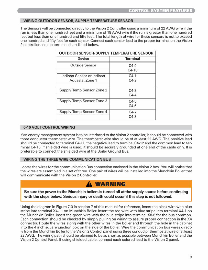
WIRING OUTDOOR SENSOR, SUPPLY TEMPERATURE SENSOR
The Sensors will be connected directly to the Vision 2 Controller using a minimum of 22 AWG wire if therun is less than one hundred feet and a minimum of 18 AWG wire if the run is greater than one hundredfeet but less than one hundred and fifty feet. The total length of wire for these sensors is not to exceedone hundred and fifty feet for each sensor. Connect each sensor lead to the proper terminal on the Vision2 controller see the terminal chart listed below.
0-10 VOLT CONTROL WIRING
If an energy management system is to be interfaced to the Vision 2 controller, it should be connected withthree conductor thermostat wire. The thermostat wire should be of at least 22 AWG. The positive leadshould be connected to terminal C4-11, the negative lead to terminal C4-12 and the common lead to ter-minal C4-16. If shielded wire is used, it should be securely grounded at one end of the cable only. It ispreferable to connect the shielded wire at the Boiler Ground Bus.
WIRING THE THREE WIRE COMMUNICATION BUS
Locate the wires for the communication Bus connection enclosed in the Vision 2 box. You will notice thatthe wires are assembled in a set of three. One pair of wires will be installed into the Munchkin Boiler thatwill communicate with the Vision 2 Controller.
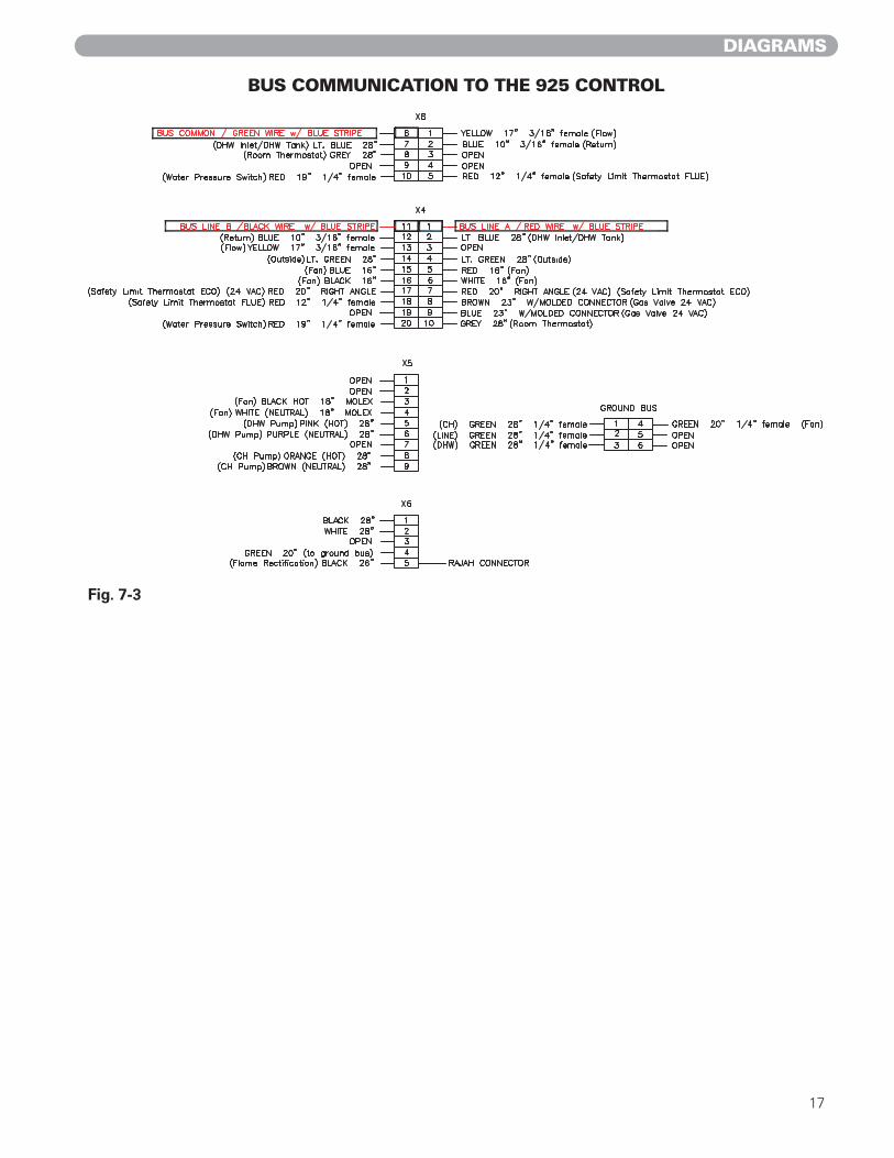
Using the diagram in Figure 7-3 in section 7 of this manual for reference, insert the black wire with bluestripe into terminal X4-11 on Munchkin Boiler. Insert the red wire with blue stripe into terminal X4-1 onthe Munchkin Boiler. Insert the green wire with the blue stripe into terminal X8-6 for the bus common.Each connection should be checked by simply pulling on wiring to assure proper connection in the X4connector. Route the wires along with the other wires in the boiler and through the hole in the cabinetinto the 4 inch square junction box on the side of the boiler. Wire the communication bus wires direct-ly from the Munchkin Boiler to the Vision 2 Control panel using three conductor thermostat wire of at least22 AWG. The wiring path should be planned to be as short as possible between Munchkin Boiler and theVision 2 Control Panel. If using shielded cable, connect each colored lead to the Vision 2 panel.
WARNING Be sure the power to the Munchkin boilers is turned off at the supply source before continuingwith the steps below. Serious injury or death could occur if this step is not followed.
OUTDOOR SENSOR/SUPPLY TEMPERATURE SENSORDevice Terminal
Outside Sensor C4-9C4-10
Indirect Sensor or IndirectAquastat Zone 1
C4-1C4-2
Supply Temp Sensor Zone 2 C4-3C4-4
Supply Temp Sensor Zone 3 C4-5C4-6
Supply Temp Sensor Zone 4 C4-7C4-8

CONTROL SYSTEM FEATURES / PROGRAMMING / PROGRAM ACCESS
10
WIRING MULTIPLE VISION 2 PANELS AND CONNECTION TO VISION 3
If multiple Vision 2 panels are used or Vision 3 is used, connect the bus wires in parallel directly from ter-minal C4-13, C4-14 and C4-15 on the Vision 2 to terminal strip C4-13, C4-14 and C4-15 on the Vision 3or to the next Vision 2. Refer to drawing V2/V3-E1 for an example showing Munchkin Boiler connectedto both the Vision 2 and Vision 3 panel.
SECTION 6: VISION 2 PROGRAMMING The Vision Dealer is the only one qualified to set the system limits and program the outdoor reset curvefor each of the mixed zones on the Vision 2 Controller. These system limits cannot be changed once theyare programmed, by anyone except an authorized Vision Dealer. The owner can only make adjustmentsto the Central Heating Set Point for each mixed zone.
Programming the Vision 2 Controller is quite simple. It is recommended that you write down the settingson the control program reference chart provided in this Section 7, Figure 7-1 for future reference. All thefeatures functions can be programmed right from the display located with your Vision 2 system.
PROGRAMMING VISION 2 BUS ADDRESS
It is important when using more than one Vision 2 panel that a Busaddress be selected through selection of certain dip switches whichwill give each Vision 2 Controller a unique address thus avoiding com-munication errors in the system. On the right is a chart which showshow to select the possible address through the dip switch for up toeight Vision 2 Control Panels.
Fig. 5-1

PROGRAM ACCESS
11
SECTION 7: VISION 2 PROGRAM ACCESS
To start, press down and hold the S3 and S4 keys simultaneously for three seconds on your displaypanel. You will notice that the display will change to 000 . Then, with your S2/+ key on the display, pressdown until you reach 025 . This will be the pass code. To confirm the pass code is 025 , you will needto press and hold the S3 for 1 second to verify. If the pass code is entered incorrectly, the controller pro-gram function will be cancelled and the controller returns to normal operation. If the code is entered cor-rectly, the controller will display the “1” alternating value of 1. You are now in the first function and readyto navigate through the system parameters.
VISION 2 PROGRAM NAVIGATION
Next, you will have to press the S3 key to move through each function. To increase or decrease a value,you will need to press either the S1/– or S2/+ key to change the default value. If there is no key actionfor 1 minute, the display returns to normal operation. Changes are effective immediately but not directlystored until the S4 key is pressed down for 3 seconds, then the new program values will be set.
Listed below are the functions the installer can program into the Vision 2 Controller.
Function Default Function DescriptionValue
1 thru 4 1 Allows the user three possible configurations for mixed zones.0 = Constant Temperature1 = outdoor reset (active with warm weather shutdown)2 = outdoor reset (always active)
5 5° Allows the installer to change Min. Outside Design Temperature. (Default 5°)(Range -49°-113°) (See Section 7, Figure 7-1 to set outdoor reset curve). Thisapplies to all four of the mixed Zones.
6 185° Allows the installer to change the design Supply Water Temperature of mixedZone 1 based on the Min. Outdoor Temperature. Range 32° to 201° (SeeSection 7, Figure 7-1 to set outdoor reset curve)
7 185° Allows the installer to change the design Supply Water Temperature of mixedZone 2 based on the Min. Outdoor Temperature. Range 32° to 201° (SeeSection 7,Figure 7-1 to set outdoor reset curve)
8 185° Allows the installer to change the design Supply Water Temperature of mixedZone 3 based on the Min. Outdoor Temperature. Range 32° to 201° (SeeSection 7,Figure 7-1 to set outdoor reset curve)
9 185° Allows the installer to change the design Supply Water Temperature of mixedZone 4 based on the Min. Outdoor Temperature. Range 32° to 201° (SeeSection 7,Figure 7-1 to set outdoor reset curve)
10 68° Allows the installer to change Max. Outside Design Temperature. Range -49°to 113° ( See Section 7,Figure 7-1 to set outdoor reset curve)
CAUTION The Vision 2 cannot be programmed while there is still a call for heat! Make sure allthermostats are turned down. It is important to note that the boiler setpoint must beequal to or set to a higher value than the design supply water temperatureprogrammed into your Vision 2 for each zone. Differential adjustment on the boilershould be considered in the system design.

Function Default Function DescriptionValue
11 68° Allows the installer to change the design Supply Water Temperature of mixedZone 1 based on the Max. Outdoor Temperature. Range 32° to 201° (SeeSection 7,Figure 7-1 to set outdoor reset curve)
12 68° Allows the installer to change the design Supply Water Temperature of mixedZone 2 based on the Max. Outdoor temperature. Range 32° to 201° (SeeSection 7, Figure 7-1 to set outdoor reset curve)
13 68° Allows the installer to change the design Supply Water Temperature of mixedZone 3 based on the Max. Outdoor temperature. Range 32° to 201° (SeeSection 7, Figure 7-1 to set outdoor reset curve)
14 68° Allows the installer to change the design Supply Water Temperature of mixedZone 4 based on the Max. Outdoor temperature. Range 32° to 201° (SeeSection 7, Figure 7-1 to set outdoor reset curve)
15 68° Allows the installer to set the Lowest Temperature Limit that the Vision 2Controller will allow for mixed Zone 1. Range 32° to 201°
16 68° Allows the installer to set the Lowest Temperature Limit that the Vision 2Controller will allow for mixed Zone 2. Range 32° to 201°
17 68° Allows the installer to set the Lowest Temperature Limit that the Vision 2Controller will allow for mixed Zone 3. Range 32° to 201°
18 68° Allows the installer to set the lowest temperature limit that the Vision 2Controller will allow for mixed Zone 4. 32° to 201°
19 14° Allows the installer to change the differential setting for all four of the mixedZones. Range 0° to 45°
20 0 Minutes Allows the installer to change the post run time setting for all of the mixedZones. Range 0-25 min.
21 68° Outdoor temperature that you wish the central heating should be disabled(warm weather shut-off) Range 32° to 113°
22 30 Minutes Allows the installer to set the maximum run time for the indirect fired waterheater and the minimum run time for central heating. Range 0 to 60 minutes
ADJUSTMENT OF MIXED ZONE SET POINT AND TEMPERATURE INDICATION FROM FAHRENHEIT TO CELCIUS
Before you can change the temperature factory default set point for each mixed zone, you must makesure you set the thermostat down so there is not a call for heat. The Vision 2 controller will not memo-rize a program setting while in a heating cycle. To adjust the mixed zone supply water temperature, pressin the S3/Program Key for three seconds until you see C1 and the alternating mixed zone 1 set pointvalue. If the S3/Program is pressed again, the next consecutive function will be shown in the table below.A value can be changed by simply pushing either S1/– or S2/+ on the display, changes are stored direct-ly. The display will return to normal operation after 1 minute if there is no key action.
PROGRAM ACCESS
12
NOTICE It is important to note that the installer can adjust the heat curve down by adjustingthe mixed zone temperature set point.

PROGRAM ACCESS
13
DWH PRIORITY WITH “DIP” SWITCH #4 IN “ON” POSITION
When dip switch #4 in the “on” position, the display will show two additional functions de and dh that willallow the user to adjust the default value. Simply press the S1/– or S2/+ key to change the default to thedesired value.
PROGRAMMING THE CENTRAL HEAT CURVE
The central heating demand is detected when the room thermostat closes. When an outside sensor isconnected, the mixed Zones will automatically adjust the supply water temperature through the mod-ulating Zone Valves based on a personalized outdoor reset curve program into the Vision 2 Controller.(See Section 7, Figure 7-1).
To set your heat curve you will have to set the following parameters. This would have been establishedin the Program Navigation section. Check the figures to assure that reset parameters match your systemdesign.
1. Minimum Outside design temperature for the four mixed zoneFunction 5
2. Design Supply water temperature at the minimum design outside temperatureFunction 6 for Zone 1Function 7 for Zone 2Function 8 for Zone 3Function 9 for Zone 4
3. Maximum outside design temperatureFunction 10
4. Design Supply Water Temperature at maximum outside temperatureFunction 11 for Zone 1Function 12 for Zone 2Function 13 for Zone 3Function 14 for Zone 4
STATUS SECTION
Installers are also able to check the current status of the Vision 2 parameters by pressing the S4/Resetkey for 3 seconds. Once activated, the display will show d1 alternating to value of the actual pipe sen-sor temperature for mixed zone 1. Actual values are displayed for each function. To view the next value,simply press the S4 key to go to the next displayed value. Listed below are values that can be displayed.These values cannot be changed. To exit this menu, simply press the S3/Program key to resume nor-mal operation.
DHW Priority with “Dip Switch” #4 in “ON” PositionFunction Display Default Setting Range of Adjustment
C1 Mixed Zone 1 180 Programmed ValueC2 Mixed Zone 2 180 Programmed ValueC3 Mixed Zone 3 180 Programmed ValueC4 Mixed Zone 4 180 Programmed Valuede DHW Setpoint 119 50–185dh DHW Differential 8 1–45t Fahrenheit to Celcius F F to C
Note: These functions will only be available when moving dip switch #4 on the Vision 2 boardto the “ON” position.

PROGRAM ACCESS
14
MULTIPLE DISPLAY MIXED ZONE STATUS
To view the status of the zones, Press the Zone Status key for 1 second and the multiple display willbecome active. The upper portion of the display will show an L1 which will indicate the current statusof the individual mixed zones shown in the lower Zone section of the display. To view the next value, sim-ply press the Zone Status key to go to the next displayed value. These values cannot be changed. Toexit this status menu, simply press the S3 key to resume normal operation.
Listed below are the values that can be viewed in the status menu.L1 – Status of Mixed Zone
Stb = StandbydH = DHW Priority (Zone 1 only)CH = CH DemandFr = Frost Protection
L2 – Status of CirculatorOn or Off = Mixed Zone Circulators
L3 – Status of Mixed Zone Outputs (Percentage of the three-way valve activation mixing the cold return with the supply system)2% = Closed 98% = Fully Open
L4 – Status Target Set PointTarget set point for mixed zone 1 through 4 based on outdoor temperature and installerprogrammed heat curve
L5 – Status of Temperature Output of Mixed Zone.Actual temperature from strap on pipe sensor of mixed zone 1 through 4
STATUS MENU
Function ValueD1/ Actual Temperature from the Supply Temperature Sensor Mixed Zone 1D2/ Actual Temperature from the Supply Temperature Sensor Mixed Zone 2D3/ Actual Temperature from the Supply Temperature Sensor Mixed Zone 3D4/ Actual Temperature from the Supply Temperature Sensor Mixed Zone 4D5/ Actual Temperature from the outdoor sensorD6/ Status of Mixed Zone 1 Pump (0=off, 1=No)D7/ Status of Mixed Zone 2 Pump (0=off, 1=No)D8/ Status of Mixed Zone 3 Pump (0=off, 1=No)D9/ Status of Mixed Zone 4 Pump (0=off, 1=No)D10/ Status of Mixing valve Mixed Zone 1
(Percentage of valve activation 2 to 98) 2=Closed / 98=fully openD11/ Status of Mixing valve Mixed Zone 2
(Percentage of valve activation 2 to 98) 2=Closed / 98=fully openD12/ Status of Mixing valve Mixed Zone 3
(Percentage of valve activation 2 to 98) 2=Closed / 98=fully openD13/ Status of Mixing valve Mixed Zone 4
(Percentage of valve activation 2 to 98) 2=Closed / 98=fully openD14/ Status of Bus connection (Co=connected, Nc=not connected)D15/ Central Heating Set Point for Mixed Zone 1
(will automatically change based on a 1-10 volt input or the outdoor reset curve)D16/ Central Heating Set Point for Mixed Zone 2
(will automatically change based on a 1-10 volt input or the outdoor reset curve)D17/ Central Heating Set Point for Mixed Zone 3
(will automatically change based on a 1-10 volt input or the outdoor reset curve)D18/ Central Heating Set Point for Mixed Zone 4
(will automatically change based on a 1-10 volt input or the outdoor reset curve)

15
VISION II PROGRAM NAVIGATION
TABLES
Resistance Table for Boiler, Indirect and Supply Temperature SensorOutside Temperature (˚F) Resistance (ohms) Boiler, Indirect & Supply Temp. Sensor Temp. (˚F) Resistance (ohms)
-22 171800 32 32550-13 129800 41 25340-4 98930 50 198705 76020 59 15700
14 58880 68 1249023 45950 77 1000032 36130 86 805941 28600 95 653550 22800 104 533059 18300 113 437268 14770 122 360577 12000 131 298986 9804 140 249095 8054 149 2084
104 6652 158 1753113 5522 167 1481
176 1256Replacement part #'s 1070
Outdoor Sensor 7250P-319 915Indirect Sensor 7250P-325 786Supply Temperature Sensor 7250P-324 667
Resistance Table for Outdoor Sensor
Fig. 7-1
Function Default Setting Installer Design Programmed Setting1 12 13 14 15 5° F6 185° F7 185° F8 185° F9 185° F10 68° F11 68° F12 68° F13 68° F14 68° F15 68° F16 68° F17 68° F18 68° F19 14.4° F20 0 minutes21 68° F22 30 minutes

16
DIAGRAMS
Fig.
7-2
VIS
ION
2 C
ON
TR
OLL
ER
17
DIAGRAMS
BUS COMMUNICATION TO THE 925 CONTROL
Fig. 7-3

18
PIPING
Piping Symbol Legend
circulator (w/ isolation flanges)
gate valve
globe valve
ball valve
swing-check valve
flow-check valve
spring-loaded check valve
hose bib / boiler drain
thermostatic radiator valveTRV (straight)
circuit setter
manual 3-way valve
zone valve
air separator
backflow preventer
diaphragm-type expansion tank
pressure reducing valve
diff. pressure bypass
anti-scald ratedmixing valve
pressure gauge
4-way motorized mixing valve
3-way motorized mixing valve
pressure relief valve
float -typeair vent
heat exchanger
union
Munchkin heater
radiant manifold
Super Storindirect DHW tank
vacuum breaker
thermostatic radiator valveTRV (angle)
circulator w/ integral flow check)
T/P
temperature / pressure gauge
REFER TO NOTE 13REFER TONOTE 13
REFER TONOTE 13
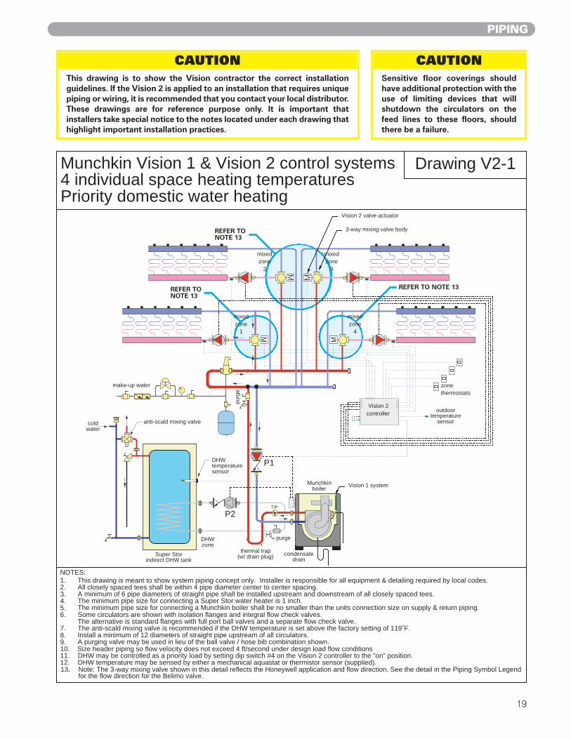
Munchkin Vision 1 & Vision 2 control systems4 individual space heating temperaturesPriority domestic water heating
Drawing V2-1
NOTES:1. This drawing is meant to show system piping concept only. Installer is responsible for all equipment & detailing required by local codes.2. All closely spaced tees shall be within 4 pipe diameter center to center spacing.3. A minimum of 6 pipe diameters of straight pipe shall be installed upstream and downstream of all closely spaced tees.4. The minimum pipe size for connecting a Super Stor water heater is 1 inch.5. The minimum pipe size for connecting a Munchkin boiler shall be no smaller than the units connection size on supply & return piping.6. Some circulators are shown with isolation flanges and integral flow check valves.
The alternative is standard flanges with full port ball valves and a separate flow check valve. 7. The anti-scald mixing valve is recommended if the DHW temperature is set above the factory setting of 119˚F.8. Install a minimum of 12 diameters of straight pipe upstream of all circulators.9. A purging valve may be used in lieu of the ball valve / hose bib combination shown.10. Size header piping so flow velocity does not exceed 4 ft/second under design load flow conditions11. DHW may be controlled as a priority load by setting dip switch #4 on the Vision 2 controller to the "on" position.12. DHW temperature may be sensed by either a mechanical aquastat or thermistor sensor (supplied).13. Note: The 3-way mixing valve shown in this detail reflects the Honeywell application and flow direction. See the detail in the Piping Symbol Legend
for the flow direction for the Belimo valve.
LNG
Munchkinboiler
DHW temperature sensor
purge
Super Storindirect DHW tank
anti-scald mixing valve
outdoortemperature
sensor
thermal trap(w/ drain plug)
P1
P2
coldwater
make-up water
DHWzone
condensatedrain
Vision 1 system
3-way mixing valve body
Vision 2 valve actuator
zonethermostats
mixed zone
4
mixed zone
1
mixed zone
2
mixed zone
3
Vision 2controller
4321
1234
4 3 2 1
purg
e
T/P
19
PIPING
CAUTION This drawing is to show the Vision contractor the correct installationguidelines. If the Vision 2 is applied to an installation that requires uniquepiping or wiring, it is recommended that you contact your local distributor.These drawings are for reference purpose only. It is important thatinstallers take special notice to the notes located under each drawing thathighlight important installation practices.
CAUTION Sensitive floor coverings shouldhave additional protection with theuse of limiting devices that willshutdown the circulators on thefeed lines to these floors, shouldthere be a failure.

REFER TONOTE 15
20
PIPING
Munchkin Vision 2 control systemTwo individual space heating temperaturesDomestic water heatingSub-zoning using zone valves
Drawing V2-2
NOTES:1. This drawing is meant to show system piping concept only. Installer is responsible for all equipment & detailing required by local codes.2. All closely spaced tees shall be within 4 pipe diameter center to center spacing.3. A minimum of 6 pipe diameters of straight pipe shall be installed upstream and downstream of all closely spaced tees.4. The minimum pipe size for connecting a Super Stor water heater is 1 inch.5. The minimum pipe size for connecting a Munchkin boiler shall be no smaller than the units connection size on supply & return piping.6. Some circulators are shown with isolation flanges and integral flow check valves.
The alternative is standard flanges with full port ball valves and a separate flow check valve. 7. The anti-scald mixing valve is recommended if the DHW temperature is set above the factory setting of 119˚F.8. Install a minimum of 12 diameters of straight pipe upstream of all circulators.9. A purging valve may be used in lieu of the ball valve / hose bib combination shown.10. Size header piping so flow velocity does not exceed 4 ft/second under design load flow conditions11. DHW may be controlled as a priority load by setting dip switch #4 on the Vision 2 controller to the "on" position.12. DHW temperature may be sensed by either a mechanical aquastat or thermistor sensor (supplied).13. Sub-zoning is accomplished by using zone circulators and multi-zone relay centers.14. The Vision 2 controller can operate up to 4 mixing valves. 15. Note: The 3-way mixing valve shown in this detail reflects the Honeywell application and flow direction. See the detail in the Piping Symbol Legend
for the flow direction for the Belimo valve.
Munchkin boiler
P1
Super Storindirect DHW tank
anti-scald mixing valvecold
water
make-up water
zone 2
outdoortemperature
sensor
3-way mixing valve body
multi-zonerelay center
multi-zonerelay center
subzone thermostats
subzone thermostats
Vision 2 valve actuator
mixedzone 1
mixed
purge
purgepurge
condensatedrain
LNG
4321
1234
4 3 2 1 1 2 3 4
Vision 2controller
sub-
zone
1
sub-
zone
3
sub-
zone
2
sub-
zone
1
sub-
zone
2
DHWzone
T/P
CAUTION This drawing is to show the Vision contractor the correct installationguidelines. If the Vision 2 is applied to an installation that requires uniquepiping or wiring, it is recommended that you contact your local distributor.These drawings are for reference purpose only. It is important thatinstallers take special notice to the notes located under each drawing thathighlight important installation practices.
CAUTION Sensitive floor coverings shouldhave additional protection with theuse of limiting devices that willshutdown the circulators on thefeed lines to these floors, shouldthere be a failure.

REFER TONOTE 15
21
PIPING
Munchkin Vision 2 control systemTwo individual space heating temperaturesDomestic water heatingSub-zoning using zone circulators
Drawing V2-3
NOTES:1. This drawing is meant to show system piping concept only. Installer is responsible for all equipment & detailing required by local codes.2. All closely spaced tees shall be within 4 pipe diameter center to center spacing.3. A minimum of 6 pipe diameters of straight pipe shall be installed upstream and downstream of all closely spaced tees.4. The minimum pipe size for connecting a Super Stor water heater is 1 inch.5. The minimum pipe size for connecting a Munchkin boiler shall be no smaller than the units connection size on supply & return piping.6. Some circulators are shown with isolation flanges and integral flow check valves.
The alternative is standard flanges with full port ball valves and a separate flow check valve. 7. The anti-scald mixing valve is recommended if the DHW temperature is set above the factory setting of 119˚F.8. Install a minimum of 12 diameters of straight pipe upstream of all circulators.9. A purging valve may be used in lieu of the ball valve / hose bib combination shown.10. Size header piping so flow velocity does not exceed 4 ft/second under design load flow conditions11. DHW may be controlled as a priority load by setting dip switch #4 on the Vision 2 controller to the "on" position.12. DHW temperature may be sensed by either a mechanical aquastat or thermistor sensor (supplied).13. Sub-zoning is accomplished by using zone circulators and multi-zone relay centers.14. The Vision 2 controller can operate up to 4 mixing valves. 15. Note: The 3-way mixing valve shown in this detail reflects the Honeywell application and flow direction. See the detail in the Piping Symbol Legend
for the flow direction for the Belimo valve.
Munchkin boiler
Super Storindirect DHW tank
anti-scald mixing valvecold
water
make-up water
outdoortemperature
sensor
multi-zonerelay center
multi-zonerelay center
zone thermostats
zone thermostats
sub-zone 1
sub-zone 2
sub-zone 1
sub-zone 2
sub-zone 3
mixedzone 2
mixedzone 3
T/P
condensatedrain
Vision 2controllerL
NG
4321
1234
4 3 2 1 1 2 3 4
purge
purge
purge
DHWzone
CAUTION This drawing is to show the Vision contractor the correct installationguidelines. If the Vision 2 is applied to an installation that requires uniquepiping or wiring, it is recommended that you contact your local distributor.These drawings are for reference purpose only. It is important thatinstallers take special notice to the notes located under each drawing thathighlight important installation practices.
CAUTION Sensitive floor coverings shouldhave additional protection with theuse of limiting devices that willshutdown the circulators on thefeed lines to these floors, shouldthere be a failure.

REFER TONOTE 16
22
PIPING
Drawing V2-4
NOTES:1. This drawing is meant to show system piping concept only. Installer is responsible for all equipment & detailing required by local codes.2. All closely spaced tees shall be within 4 pipe diameter center to center spacing.3. A minimum of 6 pipe diameters of straight pipe shall be installed upstream and downstream of all closely spaced tees.4. The minimum pipe size for connecting a Super Stor water heater is 1 inch.5. The minimum pipe size for connecting a Munchkin boiler shall be no smaller than the units connection size on supply & return piping.6. Some circulators are shown with isolation flanges and integral flow check valves.
The alternative is standard flanges with full port ball valves and a separate flow check valve. 7. The anti-scald mixing valve is recommended if the DHW temperature is set above the factory setting of 119˚F.8. Install a minimum of 12 diameters of straight pipe upstream of all circulators.9. A purging valve may be used in lieu of the ball valve / hose bib combination shown.10. Size header piping so flow velocity does not exceed 4 ft/second under design load flow conditions11. DHW may be controlled as a priority load by setting dip switch #4 on the Vision 2 controller to the "on" position.12. DHW temperature may be sensed by either a mechanical aquastat or thermistor sensor (supplied).13. Sub-zoning is accomplished by using zone circulators and multi-zone relay centers.14. Vision 2 controller can operate up to 4 mixing valves. 15. Vision 3 controller can operate up to 8 Munchkin boilers.
Munchkin Vision 2 control systemTwo boilers controlled in modulating stagesTwo individual space heating supply temperaturesDomestic water heatingSub-zoning using circulators
condensatedisposal
2-wire communications
bus
make-up water
Super Storindirect DHW tank
anti-scald mixing valvecold
water
outdoortemperature
sensor
DHW temperature sensor
3-way mixing valve body
multi-zonerelay center
multi-zonerelay center
zone thermostats
zone thermostats
Vision 2 PWM valve actuator
sub-zone 1
sub-zone 2
mixedzone 2
Vision 3controller
LNG
4321
1234
4 3 2 1
Vision 2controller
1 2 3 4
T/P T/P
mixedzone 1
boiler 2boiler 1
purge purge
purge
DHWzone
sub-zone 1
sub-zone 2
sub-zone 3
16. Note: The 3-way mixing valve shown in this detail reflects the Honeywell application and flow direction. See the detail in the Piping Symbol Legend for the flow direction for the Belimo valve.
CAUTION This drawing is to show the Vision contractor the correct installationguidelines. If the Vision 2 is applied to an installation that requires uniquepiping or wiring, it is recommended that you contact your local distributor.These drawings are for reference purpose only. It is important thatinstallers take special notice to the notes located under each drawing thathighlight important installation practices.
CAUTION Sensitive floor coverings shouldhave additional protection with theuse of limiting devices that willshutdown the circulators on thefeed lines to these floors, shouldthere be a failure.

23
PIPING
Munchkin Vision 2 zone mixing system operating single Munchkin boiler (three mixed space heating zones & priority DHW)
Drawing V2-E2
NOTES:1. All electrical wiring must be in conformance with the National Electrical Code.2. All line voltage wiring shall be minimum #14 AWG copper.3. All low voltage wiring shall be minimum #22 AWG copper4. Ground shield of shielded cable on one end only (to terminal 15 on Vision 2 controller).5. Do not route sensor wiring adjacent to line voltage wiring.6. Configuration shown above operates DHW load through Vision 2 controller along with 3 mixed space heating supply temperatures. (other conÞgurations are possible).7. In the configuration shown the DHW temperature is monitored by a thermistor sensor connected to Vision 2 controller. A DHW aquastat is also an option.8. Connect the indirect sensor (7250P-325) or indirect aquastat for DHW priority.9. In an electrically noisy environment, 3-wire shielded cable may be required in lieu of thermostat wire.
X8 X4X5 X6
6.3 A FUSE
RIBBON!CABLE!CONNECTION
COMPUTERCONNECTION
DHW!PUMP
HEATINGPUMP
RE
LAY
RE
LAY
RE
LAY
RE
LAY
RE
LAY
RE
LAY
X3
X2
HEAT TRANSFER PRODUCTS925 CONTROL BOARD
RE
LAY
RE
LAY
RE
LAY
RE
LAY
RE
LAY
RE
LAY
X3
X2
B
A
120 VAC !circuit
T-statzone
3
T-statzone
4
Vision 2 controllerC1
C2 C3
C4
1112
13151
23
45
67
89
1011
1213
1415
16
Line
Neutral
L
N
zone 4circulator L
N
Ground
zone 3circulator L
N
zone 2circulator L
N
1 2 3 4 5 6 7 8 9 10 11 12
zone 4mixingvalve
zone 3mixingvalve
zone 2mixingvalve
1 2 3 4 5 6 7 8 9 10
T-statzone
2
12
34
on
DIP switch
24VAC
12
34
56
78
910
outdoor
temp.
mix
ed z
one
supp
ly te
mp.
sen
sors
circulator zone 1
circulator zone 2
circulator zone 3
circulator zone 43-wire thermostat cable(see note 9)
DHW tankcirculator
14DHW indirect sensor, or aquastat(see note 8)
T-statzone
1
CAUTION This drawing is to show the Vision contractor the correct installationguidelines. If the Vision 2 is applied to an installation that requires uniquepiping or wiring, it is recommended that you contact your local distributor.These drawings are for reference purpose only. It is important thatinstallers take special notice to the notes located under each drawing thathighlight important installation practices.
CAUTION Sensitive floor coverings shouldhave additional protection with theuse of limiting devices that willshutdown the circulators on thefeed lines to these floors, shouldthere be a failure.

24 © 2007,2006, 2005, 2004 Heat Transfer Products, Inc. LP-118 REV. 1/26/07
PIPING
T-statzone
3
T-statzone
4
X8 X4X5 X6
HEAT TRANSFER PRODUCTS925 CONTROL BOARD
6.3 A FUSE
RIBBONCABLECONNECTION
COMPUTERCONNECTION
DHWPUMP
HEATINGPUMP
RE
LAY
RE
LAY
RE
LAY
RE
LAY
RE
LAY
RE
LAY
X3
X2
X3
X2
X8 X4X5 X6
HEAT TRANSFER PRODUCTS925 CONTROL BOARD
6.3 A FUSE
RIBBONCABLECONNECTION
COMPUTERCONNECTION
DHWPUMP
HEATINGPUMP
RE
LAY
RE
LAY
RE
LAY
RE
LAY
RE
LAY
RE
LAY
X3
X2
X3
X2
B
A
120 VACcircuit
Vision 3 controllerC1
C2 C3
C4
12
34
56
78
910
1213
1415
1 2 3 4 5 6 7 8 9 10
12
34
56
78
910
1112
1314
15
1 2 3 4 5 6 7 8 9 10 11 12
16
Line
Neutral
B
A
barrelconnectors
Ground
Vision 2 controllerC1
C2 C3
C4
1112
1314
1512
34
56
78
910
1112
1314
1516
Line
Neutral
L
N
zone 4circulator L
N
Ground
zone 3circulator L
N
zone 2circulator L
N
1 2 3 4 5 6 7 8 9 10 11 12
zone 4mixingvalve
zone 3mixingvalve
zone 2mixingvalve
1 2 3 4 5 6 7 8 9 10
T-statzone
2
12
34
on
DIP switch
24VAC
12
34
56
78
910
outdoor
temp.
mix
ed z
one
supp
ly te
mp.
sen
sors
circulator zone 1
circulator zone 2
circulator zone 3
circulator zone 4
11
systemsupply
temperature
DHW tankcirculator
DHW indirect sensor, or aquastat(see note 9)
3-w
ire th
erm
osta
t cab
le
3-w
ire th
erm
osta
t cab
le
T-statzone
1
Munchkin Vision 2 zone mixing system operating with Munchkin Vision 3 multiple boiler system(three mixed space heating zones & priority DHW)
Drawing V2/V3-E1
NOTES:1. All electrical wiring must be in conformance with the National Electrical Code.2. All line voltage wiring shall be minimum #14 AWG copper.3. All low voltage wiring shall be minimum #22 AWG copper4. Ground shield of shielded cable on one end only (to terminal 16 on Vision 3 controller).5. Do not route sensor wiring adjacent to line voltage wiring.6. Connect 2-wire communication cables to additional Munchkin boiler through same barrel connectors.
7. Configuration shown above operates DHW load through Vision 2 controller along with 3 mixed space heating supply temperatures. (other configurations are possible).8. In the configuration shown the DHW temperature is monitored by a thermistor sensor connected to Vision 2 controller. A DHW aquastat is also an option.9. Connect the indirect sensor (7250P-325) or indirect aquastat for DHW priority.10. In an electrically noisy environment, 3-wire shielded cable may be required in lieu of thermostat wire.
CAUTION This drawing is to show the Vision contractor the correct installationguidelines. If the Vision 2 is applied to an installation that requires uniquepiping or wiring, it is recommended that you contact your local distributor.These drawings are for reference purpose only. It is important thatinstallers take special notice to the notes located under each drawing thathighlight important installation practices.
CAUTION Sensitive floor coverings shouldhave additional protection with theuse of limiting devices that willshutdown the circulators on thefeed lines to these floors, shouldthere be a failure.


