The Fitzpatrick Company 1 Operating Instruction Manual: Model “D” Comminuting Machine THE FITZPATRICK COMPANY CORPORATE HEADQUARTERS 832 INDUSTRIAL DRIVE ELMHURST, IL 60126 PHONE: (630) 530-3333 FAX: (630) 530-0832 Visit us on our Web Sites: For Headquarters: www.fitzmill.com
Transcript
The Fitzpatrick Company
1
Operating Instruction Manual:
Model “D” Comminuting Machine
THE FITZPATRICK COMPANY
CORPORATE HEADQUARTERS 832 INDUSTRIAL DRIVE
ELMHURST, IL 60126 PHONE: (630) 530-3333
FAX: (630) 530-0832
Visit us on our Web Sites: For Headquarters: www.fitzmill.com
The Fitzpatrick Company
2
TABLE OF CONTENTS
SECTION 1 SAFETY INFORMATION
1.1 Safety Practices – recommendations and warnings. 1.2 Safety Labels
SECTION 2 MACHINE SYSTEMS OVERVIEW
2.0 How to Use Your Operating Manual 2.1 How to Identify Your Machine 2.2 How to Set Up a Fitzmill Comminutor 2.3 Threaded Leg Assembly Instructions 2.4 General Description and Function
SECTION 3 SYSTEM SET UP
3.1 Operating Speeds 3.2 Motor Rotation 3.3 Belt Tension 3.4 Packing Adjustment 3.5 Rotor Blades 3.6 Rotor Sharpness
SECTION 1 SAFETY 1.1 Safety Guidelines Throughout the text of this operating manual, reference is made to specific safety practices, which must be strictly adhered to. Along with these safety measures, the following guidelines must be followed:
DO NOT operate your Fitz®Mill until you and your machine operator have
read this manual and are thoroughly familiar with the operation and use of the machine. Only trained and competent personnel should be authorized to operate or maintain the equipment.
DO NOT operate your Fitz®Mill until you are certain the electrical power source is properly grounded.
DO NOT operate your Fitz®Mill prior to evaluation of the specific product and process application for which the machine is to be used. Not all products are suited for use in this equipment. Potential harm to the operator and/or damage to the machine could occur. If you have any questions about your application, contact your local FITZPATRICK sales representative or factory customer service.
DO provide operator protective devices such as eye protection, ear protection, gloves, respirator, etc. to ensure adequate operator safety. If you have any questions about special operating conditions, contact your local FITZPATRICK sales representative or factory customer service.
DO evaluate the product and process application and take appropriate steps to ensure operator safety. As with all electrical devices, only competent and authorized personnel should attempt any machine adjustments, cleaning or repair.
DO NOT operate your Fitz®Mill with any safety devices removed, circumvented or modified in any manner! Your Fitz®Mill includes certain rotating or moving parts, some of which may present “pinch” or “grab” points. Warning signs are provided on the machinery, and protective devices and electrical safety switches are provided.
DO NOT attempt to insert hands or any type of tool to free clogged materials in
the machinery. Instead, disable the power and disassemble the machine, as per the instructions described in Section 6.3.
DO lock-out the main power disconnect and be sure that all moving components have come to a complete stop before removing any guards, beginning any disassembly or attempting access to the machine in any manner.
The Fitzpatrick Company
5
DO practice good housekeeping around the equipment. Do not allow product or oil spills to accumulate in the area. During cleaning operations, care should be taken to ensure that water or other cleaning liquids do not contact electrical components, i.e. starter, junction boxes, motors etc.
STOP THE MACHINE IMMEDIATELY if excessive noise or vibration occurs. Identify the cause and correct it before continuing.
Be certain that all lubricants and cleaning agents are compatible with the in-process product and machinery. For example, products of an oxidizing nature require special hydraulic fluids and lubricants; these in turn require special seals, and other elastomers and metals normally supplied. It is important that extreme care be exercised to bring about this chemical compatibility.
REMEMBER: THINK SAFETY FIRST! Some machines are provided with electrical controls suitable for use in potentially
explosive (hazardous) atmospheres. The user should evaluate the product and process application and take adequate steps to insure operator safety. As with all electrical devices, only competent and authorized personnel should attempt adjustment or repair.
WARNING! Systems with nitrogen inerting require proper ventilation of the
nitrogen gas which is discharged from the exhaust port or product discharge of the machine.
WARNING! If your machine is equipped with a Product Containment System
(PCS), do not operate the machine without all PCS filters in place.
WARNING!
Run machine only if all guards and safety devices are securely in place.
Never put hands into feed opening or product discharge.
Never use any tool to assist product flow.
SERIOUS INJURY MAY RESULT IF ANY OF THESE SAFETY
RULES ARE VIOLATED.
The Fitzpatrick Company
6
1.2 Safety labels
Description: Warning - Hand / Blade Fitzpatrick Part Number: 1492-0633
Description: Warning-Electrical Hazard Fitzpatrick Part Number: 1492-0636
If any of these signs do not appear on your machine or have become illegible, please contact your Fitzpatrick representative to arrange for new signs, or call
Phone (630)530-3333 Fax (630)530-0832
The Fitzpatrick Company
7
Description: Warning – Hand / Belt Fitzpatrick Part Number: 1492-0649
Description: Warning - Rotating Blade Fitzpatrick Part Number: 1492-1063
If any of these signs do not appear on your machine or have become illegible, please contact your Fitzpatrick representative to arrange for new signs, or call
Phone (630)530-3333 Fax (630)530-0832
The Fitzpatrick Company
8
Description: Danger – No Safety Grid Bars Fitzpatrick Part Number: 3492-0073
(Above for use on machines supplied without safety grid bars)
Description: Danger – Safety Grid Bars Fitzpatrick Part Number: 1492-0383
If any of these signs do not appear on your machine or have become illegible, please contact your Fitzpatrick representative to arrange for new signs, or call
Phone (630) 530-3333Fax (630) 530-0832
The Fitzpatrick Company
9
Description: Danger – General Safety Fitzpatrick Part Number: 1492-0184
Description: General Safety (Spanish) Fitzpatrick Part Number: 1492-0422
If any of these signs do not appear on your machine or have become illegible, please contact your Fitzpatrick representative to arrange for new signs, or call
Phone (630) 530-3333Fax (630) 530-0832
The Fitzpatrick Company
10
Description: Read Operating Manual Fitzpatrick Part Number: 1492-0637
If any of these signs do not appear on your machine or have become illegible, please contact your Fitzpatrick representative to arrange for new signs, or call
Phone (630) 530-3333Fax (630) 530-0832
The Fitzpatrick Company
11
SECTION 2: Machine Systems Overview 2.0 How To Use Your Complete Operating Manual
Your Fitz®Mill Operating Manual has been provided to you on USB and includes a series of folders; each containing specific information relevant to your Comminuting machine.
Below is a brief description of what is to be included
in each folder. Depending on how your machine is configured and controlled, and whether or not specific quality documents were requested with your order, you may not receive all the folders shown below. Those supplied with all machines are designated as “STANDARD”.
Fitzpatrick Calibration Procedures: (Optional)
Includes procedures for calibration of machine systems and instruments for machines so equipped.
Functional Description: (Optional) Written functional description of the machine / system and its controls. Supplied with the Advanced Documentation Package.
Manual: (Standard)
Includes the text file that forms the main body of your machine Operating Instruction Manual (includes this document).
Material Certification: (Optional)
Includes certified material test certificates, when specified with your order. Operator Interface Document: (Optional)
Includes a written description and specification of your machine Operator Interface and Software, for machines so equipped.
Operator Interface Screens (Optional)
Includes screen shots of all Operating Interface screens, for machines so equipped.
The Fitzpatrick Company
12
Parameter Sheets: (Optional) Includes Variable Frequency Drive (VFD) specifications and parameter settings for machines so equipped.
PLC & OIU Programs: (Optional)
Includes software code for machines controlled via Fitzpatrick supplied PLC and Operator Interface.
Reference Drawings: (Standard)
Includes specific drawings relevant to the design and construction of your machine. Typically includes General Arrangement / Layout, major assembly drawings, Electrical Layout and Wiring Diagrams, Process & Instrument Diagram (P&ID optional) and miscellaneous others.
Security & Password Procedures: (Optional)
Includes procedures for software access and control, for machines supplied with security enabled software.
Spare Parts List: (Standard)
Includes a Recommended Spare Parts List for your machine Specification Sheet: (Standard)
Includes a detailed specification sheet which references specific configuration details, assemblies and components of your machine
Start-up Report: (Optional)
Includes the electrical controls set-up and check-out information, as documented during final testing of your machine. Only provided on machines with computer based control.
Trouble Shooting Guide: (Standard)
Includes a trouble shooting guide (also in your manual) to aid the user in the resolution of common operating faults.
Vendor Calibration Certificates: (Optional) Includes calibration certificates for OEM supplied instruments & devices, when the machine is so equipped.
Vendor Literature: (Standard)
Includes operating manuals, specification sheets and miscellaneous data for OEM supplied components of your machine.
The Fitzpatrick Company
13
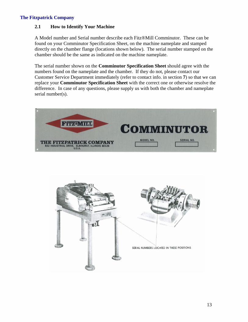
2.1 How to Identify Your Machine A Model number and Serial number describe each Fitz®Mill Comminutor. These can be found on your Comminutor Specification Sheet, on the machine nameplate and stamped directly on the chamber flange (locations shown below). The serial number stamped on the chamber should be the same as indicated on the machine nameplate. The serial number shown on the Comminutor Specification Sheet should agree with the numbers found on the nameplate and the chamber. If they do not, please contact our Customer Service Department immediately (refer to contact info. in section 7) so that we can replace your Comminutor Specification Sheet with the correct one or otherwise resolve the difference. In case of any questions, please supply us with both the chamber and nameplate serial number(s).
The Fitzpatrick Company
14
2.2 How to Set Up a Fitz®Mill Comminutor
All machines are shipped completely assembled except for the legs and miscellaneous loose parts such as extra screens, belts, dust retainers and spare parts, which are normally packed within a cardboard box, inside the machine packing crate. The legs are easily attached by slipping the straight type into cavities in the cast base and locking in place with set screws, or by bolting the flanged type to pads provided, or by screwing threaded legs into pads provided.
The electrical components have been wired in accordance with information on the Comminutor Specification Sheet. Refer to section 4 “Electrical / Controls” for electrical installation and checkout information.
CAUTION
Check the machine for shipment damage. Be sure the rotor moves freely, and that the belts are properly tensioned.
Keep in mind that this a high speed device requiring caution in operation and maintenance. Do not operate your Comminutor until you and your machine operator(s) have read this manual and are thoroughly familiar with its operation and use.
2.3 Threaded Leg Assembly Instructions The following instructions should be carefully adhered to in the assembly of your Model D Comminuting Machine. The design of the legs and method of attachment have been thoroughly researched and tested to provide a full measure of convenience, safety and value to the user. It is necessary that the assembly be accomplished according to these instructions if the advantages are to be fully realized. The threaded ends of the legs and the base sockets are threaded with a tapered pipe thread. Using this system, the leg will become tighter in its socket as it is screwed in further. The following steps should be followed in this order.
1. The legs and sockets have been cleaned and threads coated with a dry anti-seize compound prior to shipment. Upon receipt of unit, remove protective wrapping covering the threads.
2. Insert the threaded end of the leg into the base socket turning by hand until snug.
This should be approximately two to three turns of the leg. 3. With a pipe wrench no longer than 18”, continue turning the leg until tight. To
protect the leg from the wrench jaws, it may be wrapped with a damp rag, masking tape or electrical tape.
4. Repeat the above process for the remaining three legs.
The Fitzpatrick Company
15
5. Place the machine on a flat surface or level floor to check leg length.
6. If one or more casters do not contact the floor, using the same technique as
described above, tighten one or both of the adjacent legs until proper floor contact is made. Adjustment should always be made by tightening the adjacent legs rather than by loosening the shorter leg.
7. Certain models are equipped with flanged fittings on base and mating flanges on
the legs. These are simply bolted flange-to-flange with 4 bolts per flange.
It is especially important to use anti-seizing compound when assembling stainless steel legs. If any resistance is felt in tightening, the procedure should be interrupted and the threads checked for galling. Galled threads can be repaired by chasing the threads and retapping, using standard 2-1/2” IPS pipe dies and taps. Recommended anti-seize compound is LPS-1 manufactured by Holt Lloyd Corp.
The Fitzpatrick Company
16
2.4 General Description and Function The Fitzpatrick Company has been manufacturing size reduction equipment for the Pharmaceutical, Food and Chemical industries for the past 60 years. Early applications were in the Food and Bakery industry, including:
Size reduction of dehydrated potato flakes for bread products
Milling of sugar to powder for confectionery use. Shortly after our introduction into the marketplace, we also began manufacturing equipment for the Pharmaceutical and Chemical industries. Presently, we have over 25,000 size reduction units in operation worldwide. These range in size from laboratory scale to continuously operating units capable of processing up to 15 metric tons / hour.
The design of the Fitzmill Comminuting Machine allows the user to process both wet and dry products, with the capability to vary the size of the final product using the same machine. The popularity of the Fitzmill is a direct indication of the versatility of its design. A few of our milling applications include: Milling of particulate in slurries Smoothing of ointments Homogenizing / Emulsification of liquids Producing colloidal suspensions Reduction of wet massed materials prior to drying
A substantial number of our units are used for dry size reduction applications. These applications include: Controlled size reduction to provide grain size uniformity. This is apparent in grinding of
Pharmaceuticals subsequently will be tabletted, encapsulated or coated. Pulverizing granular or crystalline materials to powder for several reasons which include
o Increasing surface area of the granule for activity purposes o Pulverizing of a mix including excipient and active drugs to minimize
segregation
Another application for dry milling in deagglomeration. This is required for materials that have been in storage, or consist of a massing of particles. For this requirement, it is necessary to deagglomerate the mass without breaking the actual crystal size.
The Fitzpatrick Company
17
The variables that can be adjusted or easily changed to provide various different end results are:
Rotor Speed / Tip Speed of the blade (See attached Figure 5) Type of blades used (See attached Figure 6) Screen size and design (See attached Figure 7) Feed throat type and design (See attached Figure 8) Rate of feed to the Comminutor (See attached Figure 9).
The Fitzpatrick Company
18
The Fitzpatrick Company
19
The Fitzpatrick Company
20
SECTION 3: Machine Set Up 3.1 Operating Speeds On belt-driven machines, rotor speed is determined by three (3) parameters:
Motor pulley diameter ( Dm ) Rotor flywheel diameter ( Dr ) Motor speed ( Mrpm )
The relationship between Motor rpm ( Mrpm ) and Rotor rpm ( Rrpm ) is…
Rrpm = Mrpm x Dm ÷ Dr
Motors are typically supplied with base speeds of 1800 or 3600 rpm for 60 hertz duty (1500 or 3000 rpm for 50 hertz). Actual slip speed, as stamped on the motor nameplate, will be slightly less than these nominal ratings (e.g. 1750rpm, 3525 rpm, etc…). The Fitzpatrick Company has designed your machine to meet the rotor operating speed(s) as defined in your order documents and confirmed on the Comminutor Specification Sheet. Your Comminuting machine may be configured to achieve a desired operating speed range in one of three ways:
Single-Speed Configuration: Machine is configured with a constant speed motor and single speed pulley and flywheel for single speed operation. No adjustments are made.
Three-Speed Configuration: Machine is configured with a constant speed motor and
three speed pulley and flywheel. Three (3) discreet operating speeds may be achieved. Rotor speed is changed by repositioning the belt on the pulley and flywheel manually (refer to the figure below).
The most commonly used arrangement of this type, using an 1800 rpm motor, provides three (3) operating speeds of approximately 1000, 2450 and 4600 rpm. This arrangement provides the user the flexibility of manually selecting a wide range of operating conditions to achieve a desired material quality. Refer to the figure which illustrates the belt positions for low, medium and high speed milling.
The Fitzpatrick Company
21
Continuous-Variable Speed Range: Machine is configured with an inverter duty motor and single speed pulley and flywheel. A Variable Speed Drive may be supplied by Fitzpatrick or others. With this configuration, continuous-variable speed control can be achieved over a desired speed range to optimize milling performance and product quality.
3.2 Motor Rotation
The direction of motor rotation is indicated by an arrow on the large belt guard or throat. The motor should rotate in a forward direction such that the rotor blades travel in the same direction as the product when entering the milling chamber. When a machine is equipped with a variable speed screw (VFS), the motor driving the feed screw may be started only after the main rotor drive motor is operating. When power is applied to the machine and the main drive motor & rotor are rotating in the correct direction, the feed screw motor will rotate in the proper direction for feeding material to the mill. 3.3 Belt Tension Normally, your machine is equipped with a V-type belt drive. Correct tension of these belts is important to prevent damage to bearings, avoid belt wear, and transmit full power from the motor to the machine rotor. The motor is mounted on a sliding base and can be moved forward or backward by means of a traverse mechanism. Be sure the traverse is locked in position by tightening the set screw after tensioning the belts. Belt tensioning rules include 1.6mm allowable belt deflection per 100mm of belt span: (1/64th inch deflection per inch of belt span). The photo below illustrates a hand-held belt tension measurement device.
1. Proper tension for a V-belt drive is the lowest tension at which the belts will no slip under the highest operating load condition.
2. The tension on a new drive belt
should be checked frequently during the first day of operation.
3. The drive belt tension should be
checked periodically thereafter.
4. Too much belt tension can shorten bearing life and belt life.
5. The belts and pulleys should be
protected and kept free from any foreign material that may cause slip.
6. If a V-belt drive slips, increase belt tension before operating.
The Fitzpatrick Company
22
3.4 Packing Adjustment Your machine has been shipped with shaft seal packing installed. The packing should be inspected regularly and replaced whenever excessive wear is evident or tightening no longer prevents leakage. Refer to the Comminutor Specification Sheet to reference the rotor assembly drawing number. The rotor assembly drawing illustrates the detail of the packing gland and provides part numbers should you require replacement parts. Procedure for proper packing adjustment (applies to both sides of the rotor shaft)
1. After installing new packing rings in the gland assembly, reinstall the packing sleeve and tighten the packing sleeve bolts until hand tight, applying light pressure to the packing.
2. Using a wrench / spanner, tighten each bolt
¼ to ½ turn (beyond hand tight) to apply additional compression to the packing.
Tighten the packing sleeve bolts just enough to prevent product leakage. Over tightening the packing gland can cause excessive heat, premature wear and shorten packing life.
3.5 Rotor Blades A complete selection of rotor blades are available to meet the many and varied requirements of industry. Standard blades are illustrated in section 4. Rotor blades are generally categorized by their design. There are three basic design types:
Swinging blades Fixed-Broached blades
The type of blade used depends on the processing requirements for your specific product, and the desired characteristic for the milled material. For general milling with maximum flexibility, where both coarse size reduction or size reduction and pulverizing may be desired, a combination “225” type blade is selected. The “225” type blade has both a knife edge and a blunt “impact” edge.
The Fitzpatrick Company
23
When milling operations are limited to one or more uses of the same type (pulverizing, pureeing, etc…) blades with impact edges on both sides should be selected. Type “125” and type “625” blades are used in this case. When milling operations are limited to granulating, blades with knife-edges on both sides are selected. Types “425”, “675” and “775” are used in this case. The use of removable blade tips is indicated when the milled product is abrasive to the extent that accelerated blade wear is experienced. This also may apply in situations where a very sharp knife-edge must be maintained to achieve the desired product quality. Removable blade tips allow the user to economically maintain high milling performance, without replacement of the entire rotor/blade assembly. Additionally, impact-edged blades can be coated with high-impact resistant materials or have FitzMetal™ inserts (a special grade of tungsten carbide) to increase service life when processing abrasive materials.
3.6 Blade Sharpness The blade design selected for your machine has been chosen to provide the longest possible life and provide the desired milled product quality. The performance of your machine and milled product quality will be affected by blade sharpness. If the quality of the milled product discharged from the machine is not according to specification, or has been deteriorating over time, it is possible the blades have been become dull and require servicing or replacement. We do not recommend that blades be hand-sharpened, or that individual blades be replaced should they become damaged. New blades should be installed at the factory where the complete rotor assembly can be inspected, serviced and most importantly, dynamically balanced for your specified operating speed. Do not operate your machine with a rotor assembly that has not been dynamically balanced. This can result in vibration and noise, reduced bearing life, reduced packing life and reduction in milled product quality.
The Fitzpatrick Company
24
3.7 Water Jacketing (Optional) Some Comminutors are equipped with water cooling jackets on various machine components. The maximum recommended operating pressure in the jacketed components is typically 1 bar (15 psi). Pressure control is to be located before the inlet to the water jacket. The outlet must not be restricted. The maximum recommended flowrate for cooling water is 12 LPM (~3 GPM). Inlet water temperature is typically 4-15° C (40-60° F) but may vary based on local conditions. Check your Comminutor Specification Sheet and machine General Arrangement Drawing to confirm if your machine includes provision for water cooling. Inlet and outlet connection ports for water jackets will be indicated on your General Arrangement Drawing. Make sure your interconnecting water lines are adequately sized to provide the recommended flowrate. Typical locations for water cooling jackets on a “D” model Comminutor are:
Rotor Bearing Housing: Utilized to cool the bearings when the rotor operating speed exceeds 5000 rpm
Feed Throat: Utilized to reduce the process temperature when handling heat
sensitive products. In some highly heat-sensitive applications, connections are provided in the feed throat to inject a cryogen (e.g. liquid CO2) directly into the product stream for cooling.
Mill Chamber: Utilized to cool the milling chamber.
The Fitzpatrick Company
25
SECTION 4: Electrical / Controls 4.1 Comminutor Controls The electrical controls for Fitz®Mills are available in many configurations, ranging from simple on/off, single speed push button control to PLC / Touch Screen based, fully integrated systems. Your purchase specification, often based on the final quotation by Fitzpatrick, and the documents supplied with this manual that are specific to your machine, will fully define the specification and capabilities of your control system. All Fitz®Mills are equipped with electric safety interlock switches (one or more), located on the feed throat and also on removable hopper safety grid bars, if so equipped. Detailed electrical drawings that describe the wiring and controls for your machine are included in the “Drawings” folder on your Operating Manual CD-ROM. Always consult these documents when installing, wiring, testing and servicing your Fitz®Mill. Figure 4.1 below shows a typical machine wiring circuit for a standard Fitz®Mill motor starter panel.
Figure 4.1 – Typical Machine Wiring Circuit for Fitz®Mill
The Fitzpatrick Company
26
WARNING
NEVER ALTER OR MODIFY THE ELECTRICAL CONTROL SYSTEM IN ANY MANNER AS SERIOUS INJURY MAY RESULT. ONLY TRAINED AND AUTHORIZED ELECTRICAL PERSONNEL SHOULD PERFORM ELECTRICAL INSTALLATION OR SERVICE OF THIS MACHINE. A LOCK-OUT & TAG-OUT PROCEDURE SHOULD BE UTILIZED AND FOLLOWED DURING SERVICE. 4.2 Controls Installation Check and verify your supply voltage against that shown on the Comminutor Specification Sheet and electrical schematic drawings, prior to installation and application of electric power. Ensure that proper grounding is provided and electrical installation is in accordance with all applicable local codes and requirements. An external lock-out switch should be provided to safely isolate power from the machine during service or non-use periods. Most Fitz®Mills are provided with controls mounted locally on the machine base. Depending on the specification, a 4.5m (~15 feet) long power cord may be provided from the machine junction box for customer connection to their plant electrical supply, by hard wiring or provided with plug and receptacle. The customer may be required to drill holes or punch knockouts for electrical connections to be made. If the machine is provided with a remotely located control panel, interconnecting cable with plugs and receptacles are normally provided. If no interconnecting cable was specified, the connections between the panel and the machine are to be made by the customer’s qualified electrician and are to be carefully checked and verified after installation. Consult the electrical schematic drawings as supplied with this manual for complete wiring diagrams.
IMPORTANT NOTE
Individually test and mark both ends of each wire for identity by grounding one at a time at one end, while using a continuity tester on the other end. Only wires designated as GROUND wires should have continuity. All other wires should demonstrate no continuity (infinite resistance). Repeat this procedure for all interconnecting wires from the panel to the machine.
WARNING
Crossed or improperly grounded wires can result in potentially dangerous conditions and damage to the electrical control devices.
The Fitzpatrick Company
27
4.3 Electrical Check-Out Procedure After assembly, set-up and electrical wiring of your Fitz®Mill is complete, inspect the machine to ensure that the area is clear and all guards and safety devices are in place. Do the following:
1. Jog the rotor to verify that the direction of rotation is correct by momentarily pressing the start button and stop button. The rotor should rotate in the direction such that the blades are pulling the feed material in the direction of flow from the feed throat and should match any rotation arrows illustrated on the machine. If backwards rotation is occurring, remove and lock-out the power source. Have authorized electrical personnel disconnect and reverse two of the three power supply lead wires in the electrical enclosure. This will reverse the direction of rotor rotation.
2. Verify operation of the main motor (rotor) start, stop and speed control (if so
equipped).
3. If so equipped, verify operation of the variable feed screw drive – direction, start, stop and speed control.
4. Verify proper operation of all electrical safety interlock switches on the throat, hopper
covers, grid bars and any others that may be provided (depending on configuration of your machine).
1. Fully review this Operating Manual and especially section 1.0 – Safety Information, prior to start-up.
2. After mechanical and electrical installation requirements are complete, and motors are confirmed to be rotating in the correct direction (ref. para. 4.3), lock-out the power and unplug the power cord
3. Verify that the desired screen is installed for the product to be reduced.
4. Verify that the machine is set up for the desired rotor speed and belts are configured on the pulley and flywheel accordingly.
5. Attach the dust retainer to the chamber discharge. This device is typically adjustable and / or spring-tensioned.
Important Note:
Fitzpatrick dust retainers are air permeable (allow air to flow out during milling). This provides minimum dust generation and optimum milling results. DO NOT connect plastic drum liners or plastic bags directly between Comminutor discharge and receiver (drum). This will cause back-pressure
6. Position and attach product receiver drum to discharge end of dust retainer. This is also attached by adjusting the tension. Make certain the 6” inner skirt (if provided) is inside the drum lip to eliminate product build-up between the drum and dust retainer.
7. Reconnect electrical power to the machine.
8. Fill the hopper or feed tray with product to be processed.
9. Depress the start button to start the motor which drives the rotor. If rotor speed is adjustable through a Variable Frequency Drive, adjust the speed as desired.
10. On manual or gravity fed machines, the operator can begin feeding product into the Comminutor at a controlled feed rate. Care must be utilized not to slug or overfeed the machine, as this may cause high loads to the machine and adversely impact particle reduction and overall performance. If so equipped, motor amperage can be monitored to determine when a machine is reaching a “fully loaded” condition. Uniform amperage at 80% of full load motor nameplate amperage is considered to be the optimum production rate (capacity) for most machines.
If your machine is equipped with a variable feed screw system (VFS), continue with steps 11 and 12.
11. Depress the start button for the variable feed screw drive. This drive should be started
at its lowest speed.
12. After initial start, adjust the variable speed drive control to obtain the desired feed rate via the Variable Feed Screw system.
The Fitzpatrick Company
29
SECTION 6: Maintenance Procedures
6.1 Routine Maintenance Your Comminuting machine has been designed for minimal maintenance and maximum reliability. The machine should be inspected at regular intervals for general machine condition. The blades and rotor assembly should be checked for wear which could result in increased vibration due to loss of dynamic balance. All safety features, including warning labels, should be inspected and confirmed for proper function on a regular basis. IMPORTANT NOTE: To keep your Comminuting machine in the best possible condition, maximize performance and safety, and to maintain your warranty protection, use only Fitzpatrick supplied replacement parts when servicing your machine. The overall machine condition can typically be verified during initial start-up by listening for abnormal sounds or severe vibration. Also, check the bearing housing(s) and motor(s) for unusual or undesirable high surface temperatures. Stop the machine if any of these abnormal conditions are present and take appropriate corrective action before further operation. 6.1.1 Motors Follow the manufacturer’s recommended procedures for keeping your electric motors in the best possible working order. Some motors are supplied with sealed bearings requiring no lubrication. Other motors will include grease fittings, indicating that the motor bearings must be lubricated according to the manufacturer’s recommendation. Consult the OEM vendor literature supplied with this manual for details regarding the required maintenance of your OEM supplied devices. General instructions for greasing motor bearings are:
Stop the machine and remove/lock-out the electrical power supply to the machine.
Where motor grease fittings are present, remove the grease drain plug and pump a small amount of grease into the fill hole. A high quality, wide temperature range grease should be used, according to the motor manufacturer’s recommendation.
Replace the grease drain plug.
6.1.2 Speed Reducers (Gearboxes) Some Comminuting machines are equipped with one or more speed reduction gearboxes. When so equipped, all gearboxes must be checked for proper oil fill level prior to starting your machine. Consult the OEM vendor literature supplied with this manual for details regarding the required maintenance of your OEM supplied devices. The manufacturer’s literature will typically confirm the type of oil recommended for your devices and instructions for how to check, fill and drain lubricants.
The Fitzpatrick Company
30
Some speed reducers / gearboxes include a breather device, to prevent pressure from building within the device and causing oil leaks through the seals. If so equipped, ensure that breathers are in place, clean and functional. If the reducer is installed in an atmosphere with exceptionally high dust or moisture, a shielded or hooded vent plug should be installed. Some reducers are supplied with breathers that are temporarily sealed to prevent oil loss during shipping. Make sure temporary seals are removed prior to operation of the machine.
CAUTION The Comminutor should never be stopped under load, except in emergency, since screen plugging and main rotor overloading can occur. Always disconnect and lock-out electrical power and allow the machine rotating components to come to a complete stop before starting any disassembly or service on the machine. 6.1.3 Bearings Rotor bearings are the double row, self aligning type. The pillow block and bearings are lubricated through standard grease fittings in the top of each bearing housing. The bearings are hand-packed with grease when factory assembled. When first operated, excess grease will be discharged into the bearing housing. This should be wiped away until the bearing ceases to discharge excess grease. No additional grease should be added at this time. Over-greasing can be as detrimental to bearing life as under-greasing. Casters have sealed roller bearings which require occasional lubrication with a waterproof, high-temperature rated lubricant. 6.2 Recommended Lubrication Below is a list of high-quality, recommended bearing lubricants: Manufacturer Trade Name / Grease American Oil Company Amolith #2 Cities Service Oil Company Citgo Grease H-2 Fiske Bros. Refining Co. Lubriplate Multi-Lube “A” Exxon / Mobil Co. Mobilux Grease #2 Shell Oil Co. Alvania #2 Chevron / Texaco Multifak #2 Fitz®Mills are used under a wide variety of conditions. Therefore, the user must ultimately determine the frequency of planned maintenance and lubrication, based on their local conditions and other factors. Fitzpatrick offers these guidelines for recommended lubrication intervals for bearings and other lubricants.
The Fitzpatrick Company
31
Operation Condition Recommended Interval Intermittent, 8 hours daily 200 hours Continuous, 8 hours daily 100 hours Continuous, 24 hours daily 40 hours One shot from an average grease gun, adding a volume of grease equivalent to the size of a medium pea, is sufficient.
6.3 Machine Disassembly
WARNING
No disassembly procedure should be started unless the rotor is at rest and the motor has been disconnected from the power source.
A. Manual and Gravity Feeds To disassemble machines equipped with manual or gravity feeds:
1. Tilt back feed pan (some gravity fed machines are not equipped with feed pans – proceed to step 2).
2. Loosen fasteners which clamp down the feed throat. Remove feed throat.
3. Remove screen by withdrawing (rolling from front or rear) from front of machine chamber.
NOTE: In many applications, the unit may be disassembled to this point only for sanitizing. Please determine from your standard operating procedures if further disassembly is required.
4. Remove belt and flywheel guards.
5. Adjust motor traverse to loosen belts using handwheel. Remove drive belts.
6. Loosen packing gland nut from chamber and slide along shaft, toward the bearing.
7. Loose chamber side plate cap screws (x4). Remove chamber side plates.
CAUTION
Side plate segments are numerically matched to chamber sides and must be re-assembled in the same position so markings match on side plate segments and chamber.
8. Remove rotor assembly by loosening bearing cap screws and lifting from
chamber. 9. Loosen chamber hold down bolts and remove chamber from base.
The Fitzpatrick Company
32
Screw Feeds To disassemble machines equipped with screw feed systems (fabricated base):
1. Loosen two nuts connecting the feed screw flume to the feed throat.
2. Remove belt guards and flywheel guards.
3. Adjust motor traverse to loosen belts using handwheel. Remove drive belts.
4. The chamber is mounted in a chamber frame, which itself is mounted to the base. The flanges on each side of the frame are slotted and held in place by four fasteners. Loosen the fasteners and pull the chamber frame forward.
5. Loosen fasteners holding the feed throat. Remove the feed throat.
6. Remove screen by withdrawing from front of machine chamber.
7. Remove fasteners that retain the chamber. Remove the chamber.
8. Remove feed screw chain guard.
9. Loosen chain by traversing the variable speed drive.
10. Loosen the bolts on the back of the feed hopper, holding the feed screw bearing housing in position. Turn the feed screw until the bracket is free of mounting studs and remove.
11. Loosen or remove bolts that attach the feed hopper to the base. Remove feed hopper.
The Fitzpatrick Company
33
6.4 Cleaning your machine The design and construction of your machine allows for disassembly without the need for specialized tools. Complete disassembly of all parts is required for thorough cleaning or washing. All metal parts which contact products being processed are constructed of stainless steel and may be cleaned with hot water or steam. When the rotor is being washed, the entire chamber should NOT be immersed in water as this might permit water to enter the bearing housings. When materials processed are not water soluble, solvents or steam may be used for cleaning under proper safety conditions. Care should be taken that bearings are kept dry and lubricated. Care should also be taken that cleaning agents or solvents used are chemically compatible with elastomers and metals used in the construction of your machine (refer to your BOM and assembly drawings for parts details). Highly chlorinated cleaning solutions (e.g. bleach) are to be avoided as these can be harmful to stainless steel. 6.5 Installation of Blades, Bearings and Flywheels
DAS06 – DKAS06 – DKAS012 (Refer to your rotor cross-section drawing for details)
1. Place the center spacer or spacers on the shaft and position them in the approximate center of the spline width.
2. New blades for the model “D” Comminutors are provided in four packages of four
blades (D-6 models) or eight blades (D-12 models). Each package of blades (blade stack) has similar mass and will provide the proper static balance when assembled in the same row. Take care to keep blade stacks separated for proper balance. The four rows of blades must all be from the same stack or package of blades and will be referred to as stacks 1, 2, 3 and 4.
The Fitzpatrick Company
34
If the blades are of a symmetrical design, the orientation is not important. If the blades are NOT symmetrical, the desired forward leading edge profile should be installed in like orientation for ALL blades (i.e. knife or impact-edge forward).
3. Take two blades from the top of stack 1 for row 1 and position them on each side
of and adjacent to the center spacer. Ensure the installed orientation is with the same leading edge forward (knife or impact).
Note: Never hammer blades on to a splined shaft. Note: The blades should slip onto the broached shaft and not be abnormally tight or loose fitting.
4. Take two blades from the top of blade stack 2 for row 2 and position them on each side of and 180 degrees from and adjacent to the first pair of blades.
5. Take two blades from the top of blade stack 3, for row 3, and position them on
each side of and 90 degrees from and adjacent to the second pair of blades.
6. Take two blades from the top of blade stack 4, for row 4, and place one on each side of and 180 degrees and adjacent to the third pair of blades.
This completes the installation of the first set of 8 blades on the shaft assembly. The remaining 8 blades (D-6 models) or 24 blades (D-12 models) are installed in the same manner, starting again with 2 blades from stack 1, oriented identically to the first pair of blades (as installed in step 4). Continue to sequentially install sets of 8 blades from blade stacks 1 thru 4, as shown on your rotor assembly detail drawing. D-6 models have a total of 16 blades (2 sets of 8) and D-12 models have 32 blades (4 sets of 8).
7. Install one splined lock washer on each side of the spline, adjacent to the last blade
on each end of the shaft (total of 2 splined lock washers). 8. Install the blade lock nuts on each side of the shaft and tighten with an appropriate
wrench to the degree that any blade responds with a “ring” if lightly tapped with a steel hammer.
If the blades respond with a dull clunk sound, they are not tight. If this condition exists, and cannot be eliminated by further tightening of the lock nut, it is likely that the locknuts are bottoming out against the ends of the shaft spline, before exerting enough force to tighten the blades. Should this occur, contact The Fitzpatrick Company and we will advise the proper thickness spacers for installation on each end of the shaft, between the spline lock washer and the last blade on each end of the shaft.
The Fitzpatrick Company
35
With blades tight (ringing sound OK), tighten (do not loosen) each blade lock nut to line up on of its tool notches with one of the tangs on the blade lock washer. Bend the tang into the notch far enough to preclude the lock nut from rotating.
9. Install the packing gland followers in the orientation as shown on your rotor cross sectional drawing, on both sides of the shaft.
10. The bearing assemblies will be installed next.
Fixed-side (#2) bearing assembly: Locate the end of the shaft with the #2 stamped in the bottom of the flywheel keyway.
11. Install the inner labyrinth on the fixed-side shaft end in the orientation as shown on
your rotor cross sectional drawing. 12. Install the bearing housing labyrinth into the bearing housing in the orientation as
shown on your rotor cross sectional drawing.
13. Pre pack the bearing with the appropriate grease and install into the bearing housing in the orientation as shown on your rotor cross sectional drawing.
14. Using an electrical induction type bearing heater, heat the inner race of the bearing
in its housing to 250-300° F.
Ensure that the bearing shaft journal surface is smooth and free of any burrs and coat with light oil for installation.
15. Slide the bearing housing with the heated bearing onto the shaft in the orientation
as shown on your rotor cross sectional drawing. While the bearing is still hot, quickly install the fixed-side bearing lock washer and lock nut and tighten to ensure that the bearing has shouldered on the shaft. Let the bearing cool for 15 minutes and secure (bend) the lock washer tab into the lock nut.
16. Install the outer, fixed-side bearing cap. A lip seal is utilized on model DAS06
fixed and floating, outer bearing caps. These lip seals should be pre-installed into the caps, prior to shaft assembly.
NOTE: Model DAS06 bearing caps have left hand threads. Models DKAS06 and DKAS012 have right hand threads, and do not utilize lip seals in the bearing caps. Special spanner wrenches have been supplied with your machine, and should be used to tighten bearing caps for all models.
17. Floating-side (#1) bearing assembly: Locate the end of the shaft with the #1
stamped in the bottom of the flywheel keyway. 18. Follow the same steps as with the fixed-side (#2), except install all components on
the opposite side of the shaft (stamped #1).
The Fitzpatrick Company
36
19. Complete the rotor assembly for dynamic balancing as follows: Install the proper keys in the shaft flywheel keyways (both sides).
20. Install the proper flywheel (note that flywheels are stamped #1 and #2, corresponding to the shaft ends) on each end of the shaft. Start the flywheel ½-way on the taper, then forcibly slam it the rest of the way. It should seat with a metallic ringing sound. If not, it is “riding on the key”. This condition must be corrected by removing the flywheel and adjusting the fit of the key, usually by lightly grinding the key to reduce thickness.
21. Install lock nut and lock washers to secure the flywheels to the rotor shaft. Follow
instructions listed in the blade lock nut section of this procedure (ref. step 8).
22. At this point, the rotor assembly is ready for dynamic balancing which can be done the rotor installed in the Comminutor with suitable, portable electronic balancing equipment or with the rotor assembly installed in a special balancing rig or fixture. Dynamic balancing can be provided by a company specializing in balancing of rotating equipment. It would never be advised to attach weight to the flywheels to achieve proper balance, but rather remove weight or drill on the opposite side of the flywheel. For optimum results, it is strongly recommended that rotor re-building and balancing be performed by The Fitzpatrick Company.
The Fitzpatrick Company
37
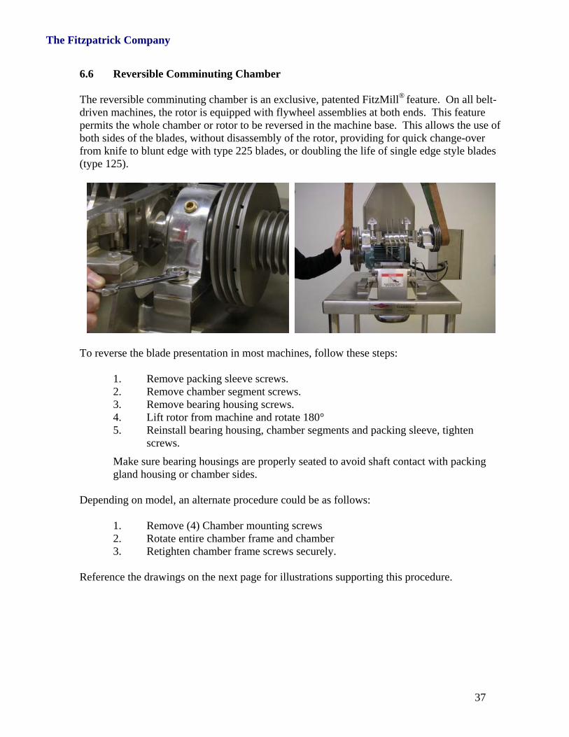
6.6 Reversible Comminuting Chamber The reversible comminuting chamber is an exclusive, patented FitzMill® feature. On all belt-driven machines, the rotor is equipped with flywheel assemblies at both ends. This feature permits the whole chamber or rotor to be reversed in the machine base. This allows the use of both sides of the blades, without disassembly of the rotor, providing for quick change-over from knife to blunt edge with type 225 blades, or doubling the life of single edge style blades (type 125).
To reverse the blade presentation in most machines, follow these steps:
Reference the drawings on the next page for illustrations supporting this procedure.
The Fitzpatrick Company
38
The Fitzpatrick Company
39
6.7 Machine Reassembly To reassemble your Comminutor machine, reverse the disassembly procedure and check to be sure the #1 floating bearing is centered in the middle of the bearing cavity. This is confirmed by bolting down the fixed #2 bearing and pushing the floating #1 bearing from left to right and back again, noting the travel distance and placing the floating #1 bearing at 50% of the observed travel distance. Then bolt it down. 6.8 Screen Installation With the feed throat removed, the screen can be installed into the chamber. The screen will protrude from the top of the chamber flange by approximately 1.5mm (1/16 inch). The inner flange of the feed throat will secure the screen in position within the chamber. No additional fasteners are required. 6.9 Machine Storage If your Comminutor is to be left idle for an extended period, it is recommended to thoroughly clean the machine of any materials processed. For long storage periods, it is recommended to clean the machine and protect it with a dust resistant cover. For best results, store the machine in a clean and dry, climate controlled area. For long term storage, electrical power should be locked-out or removed from the machine. With electrical power safely disabled, it is recommended to remove the belt guard and rotate the flywheel manually once per month. This serves to provide lubrication to the bearings and exercise the belts. Before putting your machine back into service, inspect it for any degradation from storage. Check the belt condition and tension, grease the bearings and check oil level in gearboxes (if equipped), ensure all belt guards are in place and properly secured, fasteners are tight and safety interlock switches are in place and functioning. Inspect all safety features of your machine and confirm the machine is ready for safe operation. Replace or repair any worn, damaged or missing items. When restarting your machine, listen carefully for any abnormal sounds and check for unusual vibration. These can be signs of a developing fault. Also, check the bearing housings and motor for abnormally high temperature. Stop the machine if any of these abnormal conditions are present and take appropriate corrective action before further operation.
CAUTION Never permit a machine to remain in service if a bearing failure is eminent or has already been confirmed. A bearing failure should be suspected if any unusual or increasing sound is noted during machine operation. If a bearing failure is suspected, stop the product flow, allow the chamber to clear, then shut down the machine. As the rotor comes to rest, the characteristic sound of a rough bearing will be noted as the machine coasts to rest. To avoid extensive damage to the shaft or other parts, or a potentially unsafe condition, the machine must be withdrawn from service immediately and repaired.
The Fitzpatrick Company
40
SECTION 7 How to Order Spare Parts Replacement parts should be ordered through your local sales representative or directly from the Fitzpatrick Company.
To obtain the correct part in a minimum time, the following information should be supplied with your order.
The machine serial number.
The part number, as determined from your Comminutor Specification Sheet, Bill of Material, Assembly Drawing or by Spare Parts list provided.
Description of the part.
The quantity required.
CAUTION
To ensure maximum machine performance and to maintain your warranty, use only factory-original Fitzpatrick supplied spare parts in your Comminuting Machine.
Corporate Headquarters: 832 Industrial Drive
Elmhurst, IL 60126 USA
The Fitzpatrick Company
41
SECTION 7 Recommended Spare Parts & Screens
7.1 Recommended Spare Parts List Refer to your Operating Manual CD-ROM and locate your Recommended Spare Parts List, located in the file folder “Spare Parts List”. 7.2 Special Tools – Model “D” Fitz®Mills
Spline Blade Locknut Tool
Flywheel Locknut Tool
Bearing Locknut Tool
Bearing Cap Locking Tool
Part Number Description
1391-0003 DAO Tool Set
1392-0055 Bearing Cap Tool
1392-0003 Bearing Locknut Tool
1392-0001 Flywheel Locknut Tool
1391-0004 DASO Tool Set
1392-0055 Bearing Cap Tool
1392-0003 Bearing Locknut Tool
1392-0007 Spline Blade Locknut Tool
1392-0001 Flywheel Locknut Tool
1391-0005 DKASO Tool Set
1392-0061 Bearing Cap Tool
1392-0008 Bearing Locknut Tool
1392-0045 Spline Blade Locknut Tool
1392-0038 Flywheel Locknut Tool
The Fitzpatrick Company
42
7.3 Screen List
Model DASO6 Perforated Screen List - Round Hole Screens
1. Reference your Comminuting Machine Datasheet and detailed assembly drawings for additional information with respect to specific parts of your machine.
2. You may have to refer to the manufacturer’s original documents for detail
with respect OEM supplied items (e.g. motors, controllers, devices).


![005014899 00138€¦ · 252 WILLS AND FITZPATRICK Catherine. Effects £485. FITZPATRICK Daniel. £79 15B. ti561 FITZPATRICK Edward. Effects £318 IOS. 118] FITZPATRICK Jane,](https://static.documents.pub/doc/80x56/6059be5bdbe04d125f77fe02/005014899-252-wills-and-fitzpatrick-catherine-effects-485-fitzpatrick-daniel.jpg)


