20
The Front End MAP Review Fermi National Accelerator Lab August 24-26, 2010 Harold G. Kirk Brookhaven National Laboratory
| Date post: | 22-Dec-2015 |
| Category: |
Documents |
| View: | 216 times |
| Download: | 1 times |
The Front End
MAP Review
Fermi National Accelerator Lab August 24-26, 2010
Harold G. KirkBrookhaven National Laboratory
August 24-26, 2010MAP Review-Front End Harold G. Kirk
2
Outline
Define Front End
Major Sub-systems
Key Challenges
Milestones
August 24-26, 2010MAP Review-Front End Harold G. Kirk
3
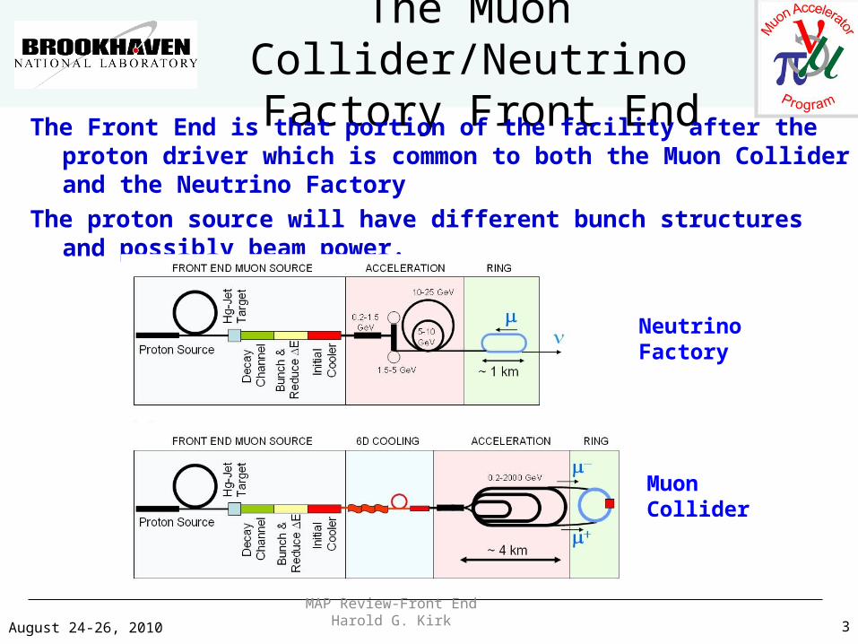
The Muon Collider/Neutrino Factory Front End
The Front End is that portion of the facility after the proton driver which is common to both the Muon Collider and the Neutrino Factory
The proton source will have different bunch structures and possibly beam power.
NeutrinoFactory
MuonCollider
August 24-26, 2010MAP Review-Front End Harold G. Kirk
4
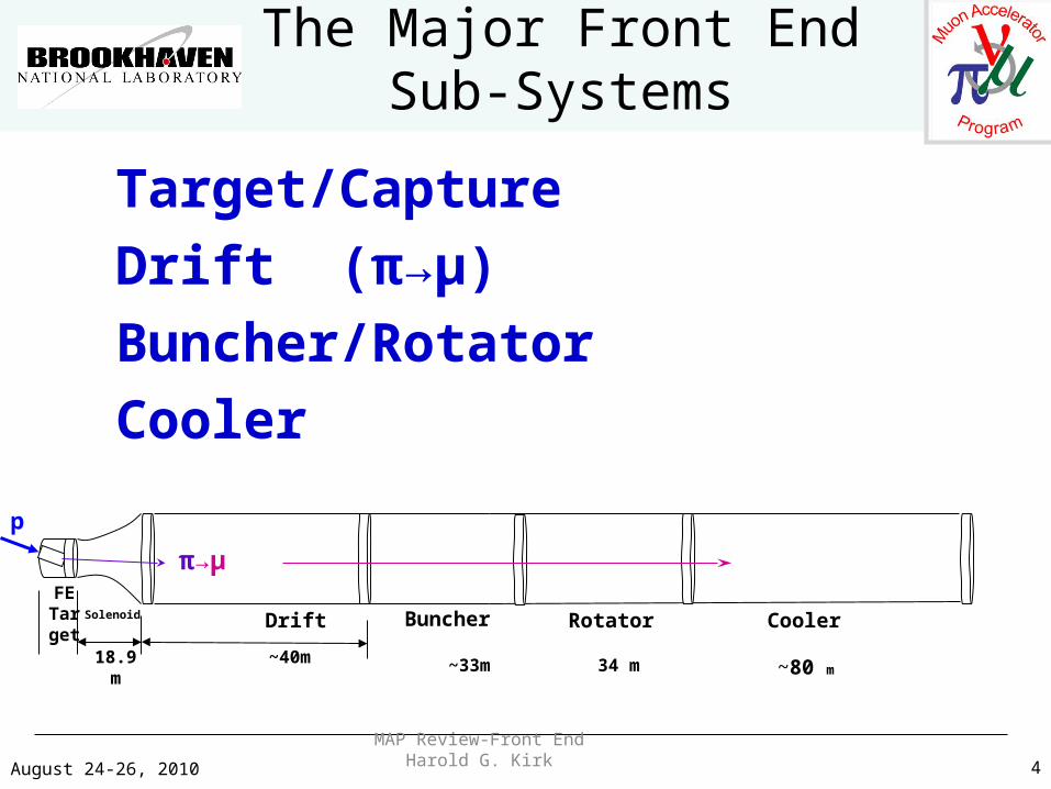
The Major Front EndSub-Systems
Target/Capture
Drift (π→μ)
Buncher/Rotator
Cooler
18.9 m ~40m
FE Targ
etSolenoid Drift Buncher Rotator Cooler
~33m 34 m ~80 m
p
π→μ
August 24-26, 2010MAP Review-Front End Harold G. Kirk
5
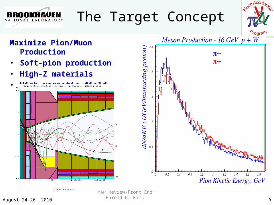
The Target Concept
Maximize Pion/Muon Production• Soft-pion production• High-Z materials• High-magnetic field
August 24-26, 2010MAP Review-Front End Harold G. Kirk
6
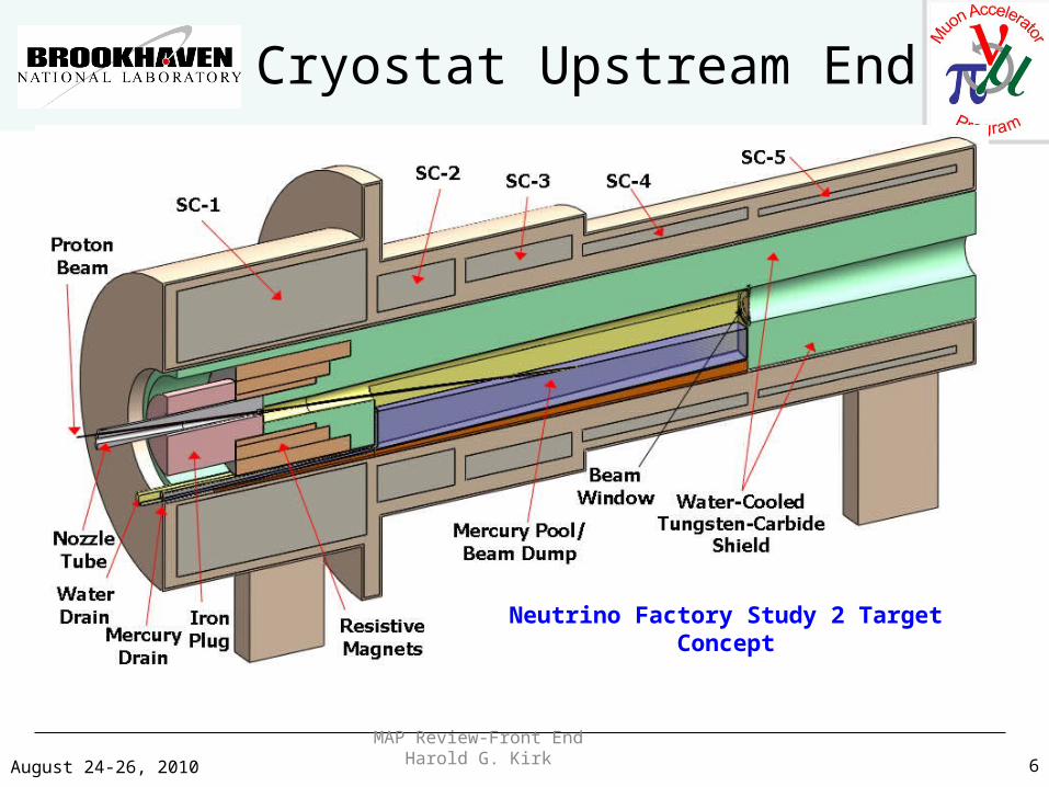
Cryostat Upstream End
Neutrino Factory Study 2 Target Concept
August 24-26, 2010MAP Review-Front End Harold G. Kirk
7
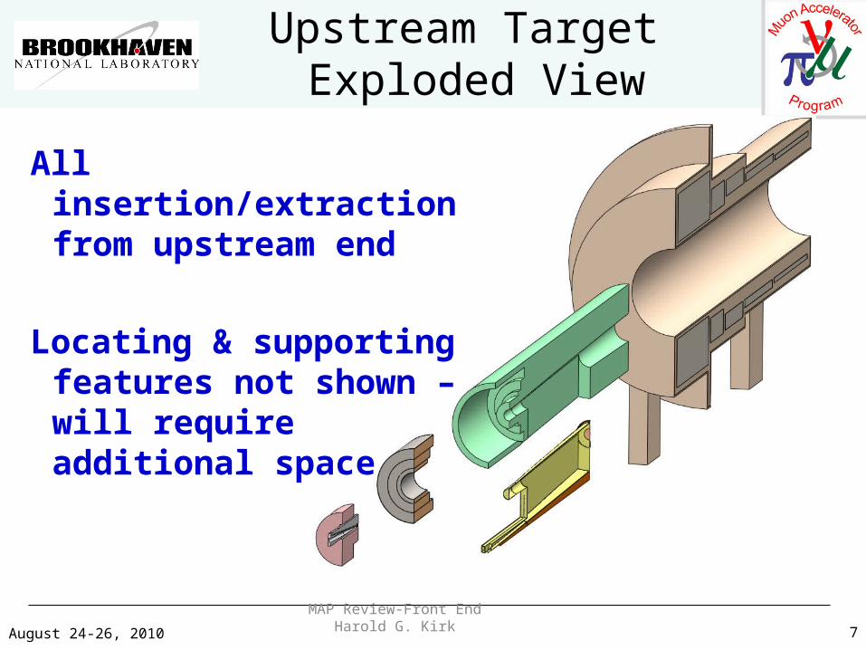
Upstream Target Exploded View
All insertion/extraction from upstream end
Locating & supporting features not shown – will require additional space
August 24-26, 2010MAP Review-Front End Harold G. Kirk
8
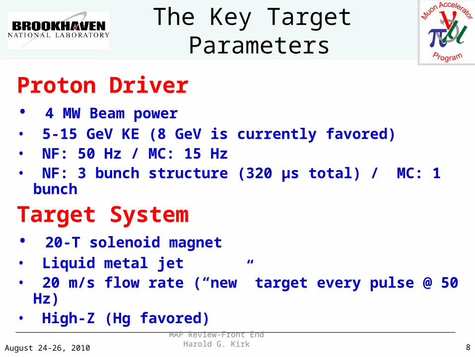
The Key Target Parameters
Proton Driver• 4 MW Beam power• 5-15 GeV KE (8 GeV is currently favored)• NF: 50 Hz / MC: 15 Hz• NF: 3 bunch structure (320 μs total) / MC: 1 bunch
Target System• 20-T solenoid magnet• Liquid metal jet• 20 m/s flow rate (“new” target every pulse @ 50 Hz)• High-Z (Hg favored)
August 24-26, 2010MAP Review-Front End Harold G. Kirk
9
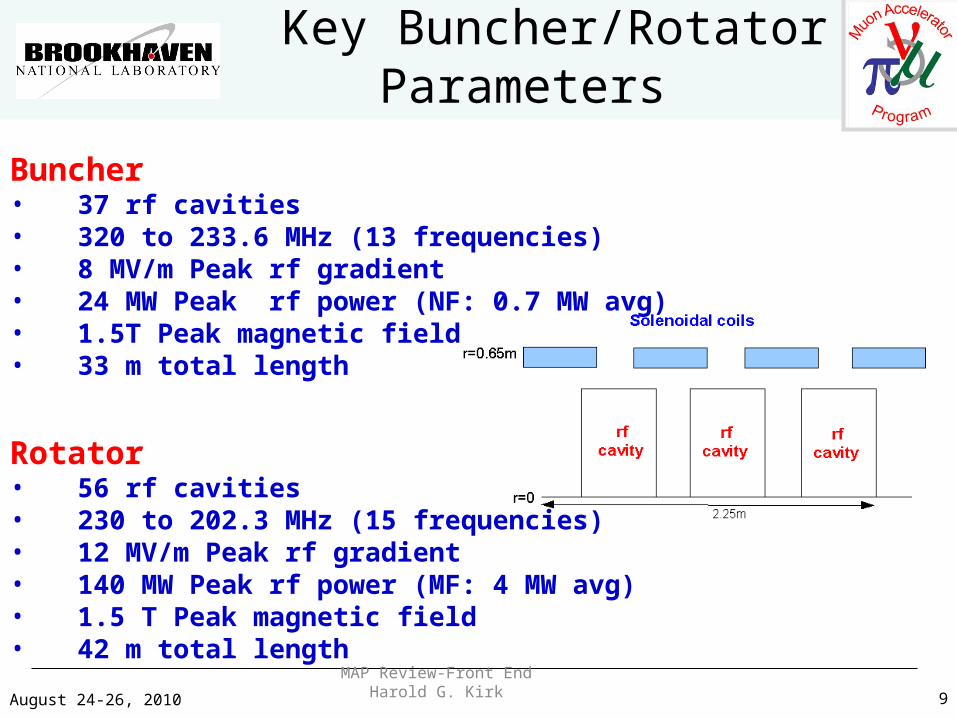
Key Buncher/RotatorParameters
Buncher• 37 rf cavities• 320 to 233.6 MHz (13 frequencies)• 8 MV/m Peak rf gradient• 24 MW Peak rf power (NF: 0.7 MW avg)• 1.5T Peak magnetic field• 33 m total length
Rotator• 56 rf cavities• 230 to 202.3 MHz (15 frequencies)• 12 MV/m Peak rf gradient• 140 MW Peak rf power (MF: 4 MW avg)• 1.5 T Peak magnetic field• 42 m total length
August 24-26, 2010MAP Review-Front End Harold G. Kirk
10
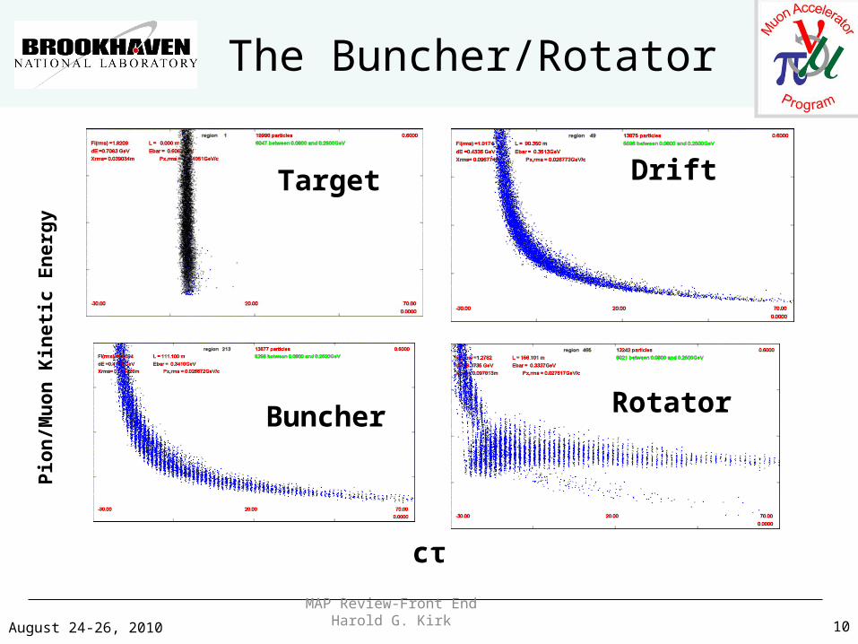
The Buncher/RotatorP
ion
/Mu
on K
inet
ic E
ner
gy
cτ
Drift
Buncher Rotator
Target
August 24-26, 2010MAP Review-Front End Harold G. Kirk
11
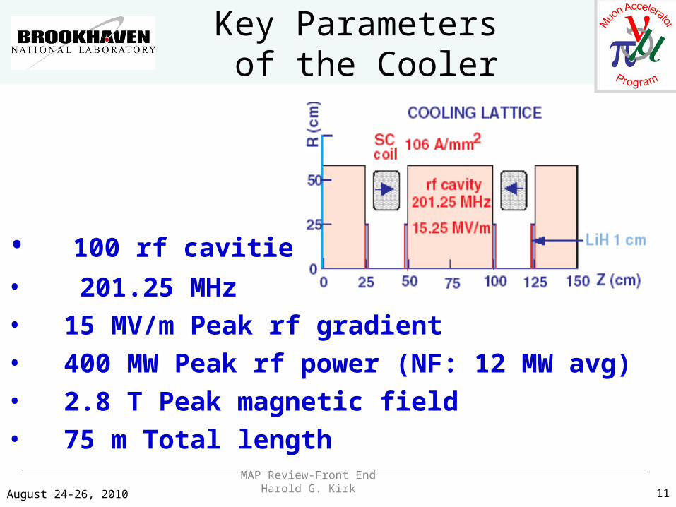
Key Parameters of the Cooler
• 100 rf cavities
• 201.25 MHz • 15 MV/m Peak rf gradient• 400 MW Peak rf power (NF: 12 MW avg)• 2.8 T Peak magnetic field• 75 m Total length
August 24-26, 2010MAP Review-Front End Harold G. Kirk
12
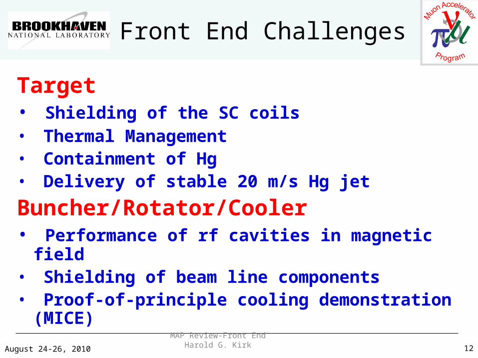
Front End Challenges
Target• Shielding of the SC coils• Thermal Management• Containment of Hg• Delivery of stable 20 m/s Hg jet
Buncher/Rotator/Cooler• Performance of rf cavities in magnetic field• Shielding of beam line components• Proof-of-principle cooling demonstration (MICE)
August 24-26, 2010MAP Review-Front End Harold G. Kirk
13
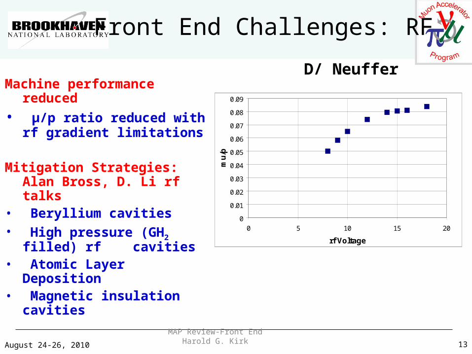
Front End Challenges: RF
Machine performance reduced
• μ/p ratio reduced with rf gradient limitations
Mitigation Strategies: Alan Bross, D. Li rf talks
• Beryllium cavities• High pressure (GH2 filled) rf
cavities• Atomic Layer Deposition• Magnetic insulation cavities
0
0.01
0.02
0.03
0.04
0.05
0.06
0.07
0.08
0.09
0 5 10 15 20
rf Voltage
mu
/p
D/ Neuffer
August 24-26, 2010MAP Review-Front End Harold G. Kirk
14
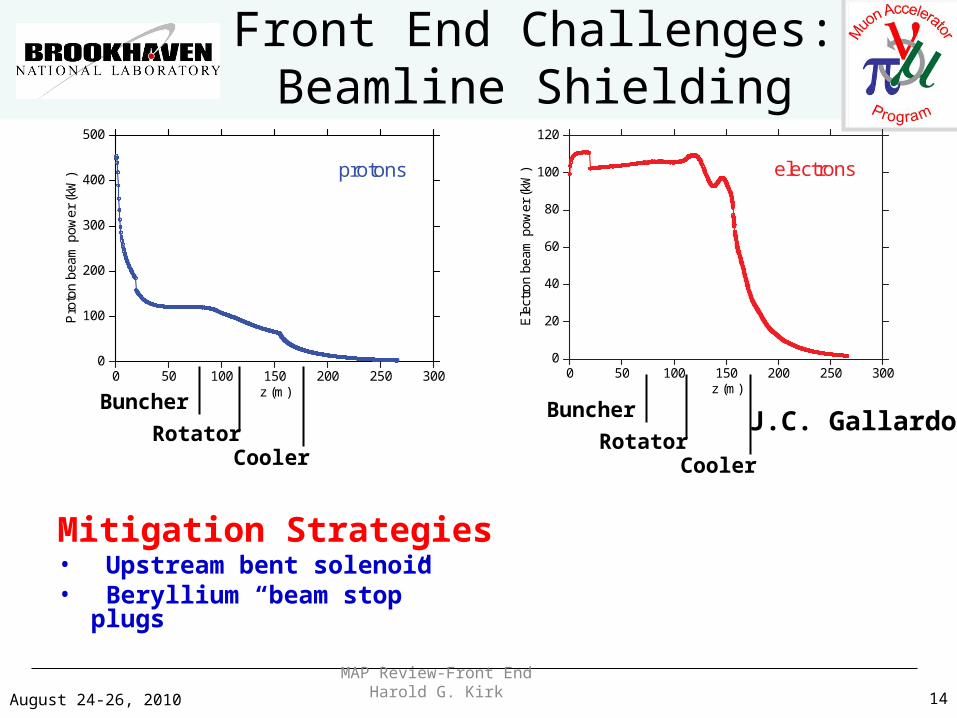
Front End Challenges:Beamline Shielding
Mitigation Strategies• Upstream bent solenoid• Beryllium “beam stop” plugs
J.C. Gallardo
electrons
00
20
40
60
80
100
120
50 100 150z (m)
200 250 300
Ele
ctro
nbe
ampo
wer
(kW
)protons
0 50 100 150z (m)
200 250 3000
100
200
300
400
500
Pro
ton
bea
mp
ower
(kW
)
Buncher
RotatorCooler
Buncher
RotatorCooler
August 24-26, 2010MAP Review-Front End Harold G. Kirk
15
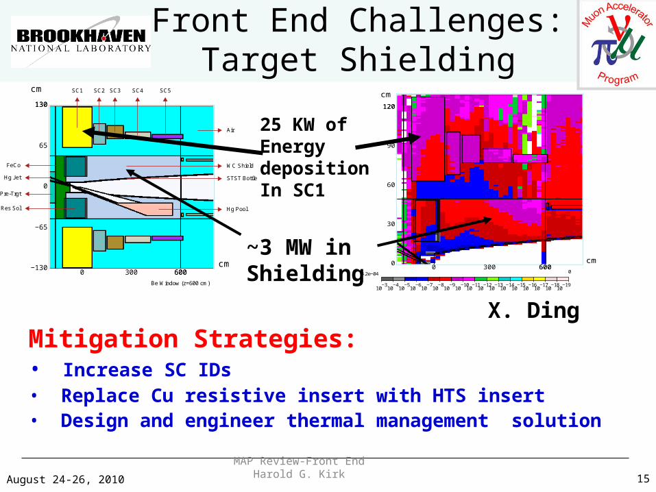
Front End Challenges:Target Shielding
Mitigation Strategies:• Increase SC IDs• Replace Cu resistive insert with HTS insert• Design and engineer thermal management solution
−130
−65
0
65
130130
cm
0 300 600600cm
Hg Jet
WC Shield
STST Bottle
Hg Pool
Air
SC5SC4SC3SC2SC1
FeCo
Pre-Trgt
Res Sol
Be Window (z=600 cm)
0
30
60
90
120120
cm
0 300 600600cm
10−310−410−510−610−710−810−910−1010−1110−1210−1310−1410−1510−1610−1710−1810−19
4.2e−04 0
25 KW ofEnergydepositionIn SC1
~3 MW inShielding
X. Ding
August 24-26, 2010MAP Review-Front End Harold G. Kirk
16
Front End Challenges: Hg Nozzle
Hg Jet• 8 mm OD
• 20 m/s for 50Hz operations• Hg jet performance in MERIT not optimal
Mitigation Strategies
• MHD simulations of jet/magnet/proton interactions
• Design and engineer nozzle delivery system • Fabricate and test prototypical nozzle design
August 24-26, 2010MAP Review-Front End Harold G. Kirk
17
Front End Challenges: Hg Target
Mercury• Low vapor pressure
• Toxic• Disperses easily upon spilling
Mitigation Strategies• Design and engineer double containment Hg system
• Explore alternatives:– PbBi eutectic– Tungsten powder flow

August 24-26, 2010MAP Review-Front End Harold G. Kirk
18
Front End Challenges: Pion Production
Current pion production modeling based on MARS15 simulations
HARP data does not support sharp falloff of pion production for proton KE < 8 GeV
Mitigation Strategies• Incorporate HARP (and MIPP)
results into MARS (underway Mokhov, et al)
• Contribute high-Z target for production experiment at 5 and 8 GeV (MIPP proposal, Torun, et al.)
August 24-26, 2010MAP Review-Front End Harold G. Kirk
19
Front End Milestones
FY10 Initial target configurationFY10 IDS-NF IDRFY11 Establish initial FE configurationFY12 Down selection of 201 rf cavity designFY12 Engineering design of Front EndFY13 Complete costing of Front EndFY14 IDS-NF RDRFY14 Interim MC DFS
August 24-26, 2010MAP Review-Front End Harold G. Kirk
20
Summary
• A Front End baseline has been established• Optimization studies have resulted in a 0.08 μ/p
throughput ratio for 8 GeV incoming protons • Key Front End challenges
– Performance of rf cavities in magnetic field– Shielding of superconducting solenoids
• Mitigation strategies have been developed to address these challenges


