Schaeffler SYMPOSIUM 2010 7 Efficient automac transmissions 106 SchaefflerSYMPOSIUM 2010 107 7 Efficient automac transmissions 7 7 Efficient automac transmissions 107 Schaeffler SYMPOSIUM 2010 Schaeffler SYMPOSIUM 2010 106 The future comes automac E fficient automac transmissions provide a basis for hybrid capable drive trains Uwe Wagner Dierk Reitz
Transcript
Schaeffl er SYMPOSIUM 2010
7 Effi cient automati c transmissions
106 Schaeffl erSYMPOSIUM 2010 107
7Effi cient automati c transmissions
7
7 Effi cient automati c transmissions
107Schaeffl er SYMPOSIUM 2010Schaeffl er SYMPOSIUM 2010106
The future comes automati cEffi cient automati c transmissions provide
a basis for hybrid capable drive trains
Uwe WagnerDierk Reitz
Schaeffl er SYMPOSIUM 2010
7 Effi cient automati c transmissions
108 Schaeffl erSYMPOSIUM 2010 109
7Effi cient automati c transmissions
7
Introducti onThe central questi on currently occupying develop-ers of transmissions is not whether there will be a breakthrough in power transmission but how quickly and in what form this will occur. The rele-vant boundary conditi ons are well known and are presented in almost every publicati on on the sub-ject of drive trains:
the increasing global importance of CO2
emissions due to the threat of climate change
the increasing urbanizati on of individual mobility and thus the increasing importance of local emissions
the divergence between the consumpti on and availability of fossil fuels
the worldwide growth in populati on and the strong growth in new markets such as China, India and Russia
The decisive criterion for the implementati on of technically feasible measures is and remains the rati o of the price that the end customer must pay
for new technologies such as hybrids, range ex-tenders or electric vehicles and the savings that he can achieve through reduced CO2 emissions. It is sti ll signifi cantly more economical for the driver to emit one gram of CO2 than to save it through such technologies. It is well known that the main reason for this is the enormous cost of batt eries. Their development in terms of price and perfor-mance capacity will be decisive in determining the electrifi cati on of the drive train in the coming years.
Furthermore, state support will play a highly sig-nifi cant role. The German Federal Government has set the ambiti ous target that the number of electric vehicles running on German roads should fi rst reach 100 000 by 2014 and then 1 000 000 by 2020. To this end, state support measures are en-visaged in both infrastructure and fi nancial terms. In additi on to the tax concept, calculati on of fl eet consumpti on and payment penalti es for non-compliance with defi ned targets will be of essen-ti al importance. Since e-mobility is to be supplied from renewable energy sources according to Gov-ernment decisions, electric vehicles will be able to be calculated as zero emission vehicles, and
this will even be possible on a multi ple basis in the years 2012 to 2015.
The effects of these boundary conditions on the transmission roadmaps of automotive manufac-turers can be clearly seen. While differences can be seen in the weighting given by the different manufacturers to the various technologies and the planned timescale, the central theme is the same almost everywhere. First of all, it is neces-sary to further optimize the drive trains of inter-nal combustion engines. For transmission sys-tems, this means further improvements in efficiency, spread, the number of gears and the dampers since running substantially without slippage is required (step 1). Stop-start systems will also develop to be the standard in many ve-hicle segments (step 2). Following this, hybrid-ization (step 3) will also be developed with an increasing proportion of plug-in applications in the direction of range extenders or electric ve-hicles (step 4).
While the measures in the fi rst two steps are clearly outlined, the implementati on and the scale of electrifi cati on of the drive train are un-derstandably sti ll relati vely unclear. The decisive point is, however, that the internal combusti on engine is sti ll seen as the dominant drive system for the next 10 years. Against this background, the automati c transmission will conti nue to gain in importance since it gives not only outstanding comfort characteristi cs but also excellent oppor-tuniti es for this step-by-step electrifi cati on of the drive train.
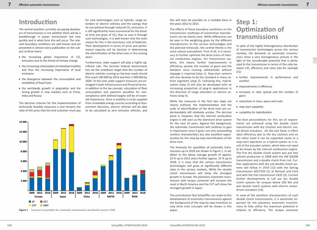
The forecasts for quanti ti es of automati c trans-missions up to 2018 are shown in Figure 1. In ad-diti on to the above average growth of approx. 25 % up to 2012 and a further approx. 23 % up to 2018, it is clear that the various transmission technologies will grow at signifi cantly diff erent rates in the various markets. While the double clutch transmission will show the strongest growth in Europe, the planetary automati c trans-mission with torque converter will increase the most in North America and the CVT will show the strongest growth in Japan.
The contribution that Schaeffler can make to this development of automatic transmissions against the background of the step-by-step transition to new drive train concepts will be shown in this paper.
Step 1: Opti mizati on of transmissionsIn spite of the highly heterogeneous distributi on of transmission technologies across the various markets, the demands on automati c transmis-sions show a very homogeneous picture in the light of the considerable potenti al that is att rib-uted to the transmission in terms of the rati o be-tween CO2 effi ciency and costs (see for example [1]):
further improvements in performance and comfort
improvements in effi ciency
increases in rati o spread and the number of gears
reducti ons in mass, space and costs
stop-start capability
suitability for hybridizati on
The best preconditions for this set of require-ments are achieved using the double clutch transmission with dry clutches and electric mo-tor-driven actuators. On the one hand, it offers ideal efficiency due to the dry clutches and on the other hand it can be expanded easily to a stop-start operation or a hybrid system as a re-sult of the actuator system, which does not need to be driven by the internal combustion engine. The first dry double clutch system was put into volume production in 2008 with the VW DQ200 transmission and a double clutch from LuK. Fur-ther applications with dry LuK double clutch sys-tems will follow in 2010 [13] with the Getrag transmission 6DCT250 [2] at Renault and Ford and with the Fiat transmission C635 [3]. Current further developments at LuK are dry double clutch systems for torques below 200 Nm and wet double clutch systems with electric motor-driven actuators [14].
In view of the excellent characteristics of such double clutch transmissions, it is extremely im-portant for the planetary automatic transmis-sions to fully utilize the maximum potential in relation to efficiency. The torque converter
Figure 1 Forecast of quanti ti es for automati c transmissions worldwide (source: CSM)
Schaeffl er SYMPOSIUM 2010
7 Effi cient automati c transmissions
110 Schaeffl erSYMPOSIUM 2010 111
7Effi cient automati c transmissions
7
should therefore ideally be locked up immedi-ately after starting and remain locked up until shortly before idling speed. Such a torque con-verter lockup clutch also offers advantages in relation to performance, since it does not need to be opened during gearshift and a shift feeling similar to a double clutch transmission can be achieved. This can be an important criterion par-ticularly with an increasing number of gears. Since excitation due to the non-uniformity of ro-tation in modern, supercharged engines increas-es to the same extent as the requirements for noise comfort, however, this leads to a conflict in objectives that can only be resolved through the use of considerably more effective damper sys-tems for the torque converter lockup clutches. A modular system of such damper concepts up to the centrifugal pendulum damper for use in torque converters is shown in [15].
There is also a growing requirement in CVT for im-proved effi ciency and higher spread. Although CVT is certainly unbeatable especially in the Japa-nese market from a customer perspecti ve in rela-ti on to comfort, it is coming increasingly under pressure due to the improvements of the com-peti tors described above. CVT variators based on link chains from LuK off er enormous potenti al in this respect, as has been shown in various exam-ples of high performance applicati ons. Further-more, this variator type off ers a highly elegant soluti on for small transmissions below 200 Nm that can also represent an economical soluti on when applied in an appropriate overall design [16].
Step 2: Stop-StartThe measures described in Step 1 serve exclusive-ly to opti mize the transmission as a mechanical converter in the drive train such that the drive side engine power can be converted as eff ecti vely as possible into the drive power required on the output side in relati on to spread, grading, dynam-ics, comfort and effi ciency. The next step in reduc-ing consumpti on and thus CO2 emissions is the intelligent use of a stop-start functi on. The poten-ti al for reducing consumpti on as a result is ap-prox. 4 % on the NEDC, so this measure is also a fi rm fi xture on the roadmaps of vehicle manufac-turers.
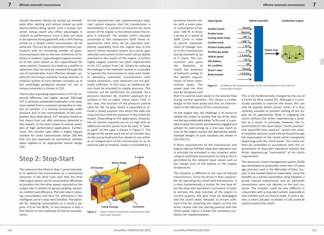
On the transmission side, implementing a stop-start system requires that the transmission is immediately in a position to transmit the drive power of the engine to the wheels when the en-gine is restarted. The double clutch concepts presented at this Symposium fulfill these re-quirements since they can be operated com-pletely separately from the engine due to the electric motor actuator system. As a result, gear selection and control of the clutch can be ideally matched to the restart of the engine. A further highly elegant solution has been implemented in the CVT system from LuK. Simply by reducing the leakage in the hydraulic system it is possible to operate the transmission in stop-start mode. In planetary automatic transmissions with torque converters, such measures are not gen-erally sufficient. In this case, an additional de-vice must be provided to supply pressure. This function can be performed, for example, by a pressure reservoir [4]. Another approach to a solution is the so-called “check valve” [15]. In this case, the function of the pressure control valve for the 1st gear clutch is expanded to in-clude a closed position into which the slide can snap and thus hold the pressure in the clutch for restart. Depending on the application, however, the oil volume required can be so high that an additional electric pump must be used. A “pow-er pack” of this type is shown in Figure 2. The design of the power pack has an oil transfer face on the pump head and thus allows its use either as an integral part of the transmission or as an external add-on module. Power is provided by a
brushless electric mo-tor with a mean pow-er consumption of ap-prox. 100 W. It drives a pump at a speed of 3000 1/min in order to permit replenish-ment of leakage loss-es in the transmission during standstill at up to 3 l/min. The con-struction also gives the flexibility to match the provision of hydraulic energy to the specific require-ments of other trans-mission types. The power pack can thus also be designed such that it is used to cover peaks in the volume flow during normal operation. This allows a smaller design of the main pump and thus an improve-ment in the efficiency of the transmission.
On the engine side, the challenge is of course to initi ate the restart so quickly that the driver does not feel any undesirable delay. To this end, it is pos-sible to leave the starter permanently engaged and achieve its overrunning by a one way clutch as soon as the engine reaches the appropriate speed. Example designs of such soluti ons are shown in [15] and [17].
If these requirements on the transmission and engine side are fulfilled, stop-start operation can in principle be activated in any situation when using an automatic transmission as long as this is permitted by the relevant input values such as the charge level of the battery or the engine temperature.
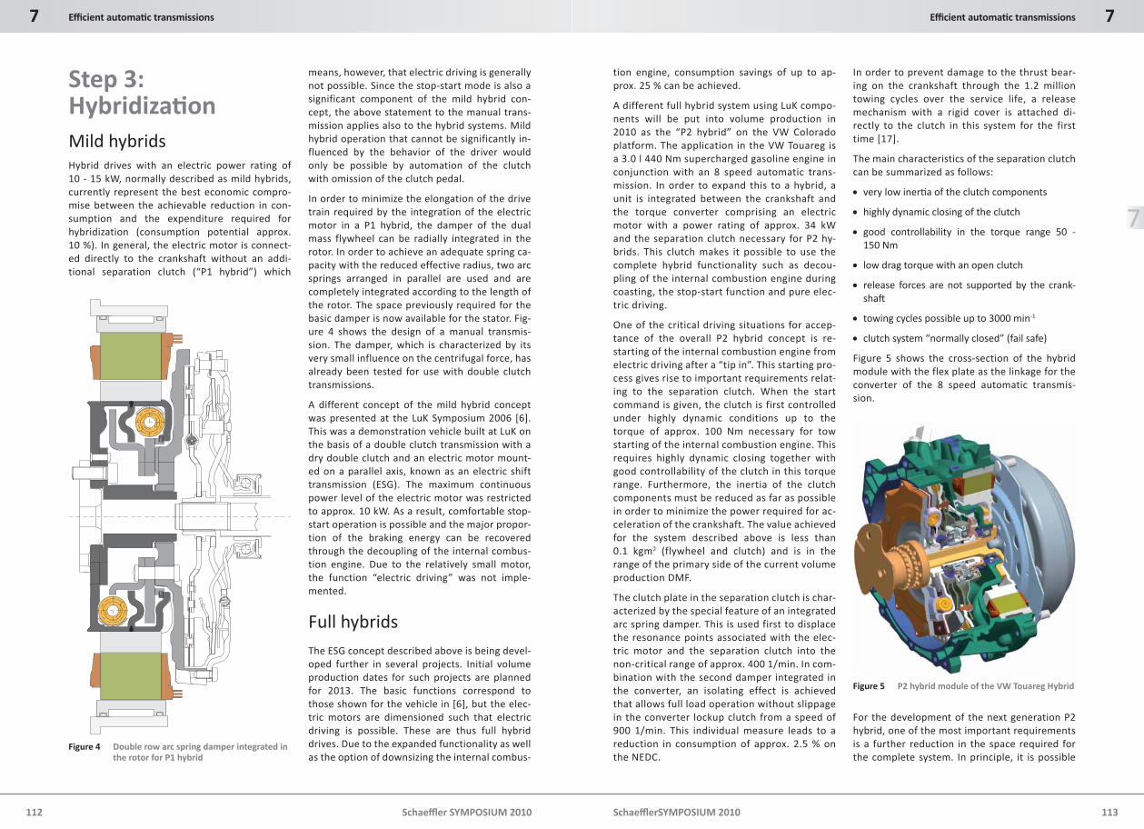
The situation is different in the case of manual transmissions. Since the driver is then responsi-ble for operating the clutch and transmission, it is then fundamentally a matter for him how of-ten the stop-start operation is activated. In order to activate the stop function of the engine in current systems, the gear must be disengaged and the clutch pedal released, to ensure suffi-cient time for restarting the engine so that the driver cannot stall the starting process with the clutch pedal. Figure 3 shows the necessary con-ditions for implementation.
This is not fundamentally changed by the use of a Clutch by Wire system [5]. Although it is tech-nically possible to overrule the driver, this can only be applied within certain limits. It is thus certainly possible to prevent stalling of the en-gine by an appropriate delay in engaging the clutch without the driver experiencing a prob-lem as a result. In principle, however, the re-quirements for the input values “clutch position” and “gearshift lever position” remain the same. A complete solution could only be found through full automation of the clutch while completely dispensing with the clutch pedal. The clutch can then be controlled in accordance with the re-quirements of stop-start operation without the driver experiencing “overcontrol” of his clutch requirement.
This electronic clutch management system (ECM) was developed to producti on more than 10 years ago and was used in the Mercedes A Class. Suc-cess in the market failed to materialize, since the benefi ts as a parti al automati on lying between a purely manual transmission and an automati c transmission were not obvious to the end cus-tomer. The situati on could be very diff erent in conjuncti on with a stop-start system, especially in new markets such as China or India. In such a sys-tem, a smart actuator as shown in [14] could be used to control the clutch.
E motor
Motor flange
Oil transfer
Pump housing Connector
Figure 2 Power Pack for automati c transmission with stop-start functi on
... ...
Input signals Hybrid controller Combus�on engine
Posi�on clutch
Posi�on lever
Cooling water temp
Catalyst temp
Posi�on brake pedal
Posi�on gas pedal
Vehicle speed
SOC Ba�ery
Air condi�on
Driver’s door
Brake booster
Closed
Neutral
>40 °C
>300 °C
>10 %
0 %
< 5 km/h
>35 %
Off
Closed
< 0,6 bar
Engine stop
Figure 3 Conditi ons for implementati on of the stop functi on in the internal combusti on engine
Schaeffl er SYMPOSIUM 2010
7 Effi cient automati c transmissions
112 Schaeffl erSYMPOSIUM 2010 113
7Effi cient automati c transmissions
7
Step 3: Hybridizati onMild hybridsHybrid drives with an electric power rating of 10 - 15 kW, normally described as mild hybrids, currently represent the best economic compro-mise between the achievable reduction in con-sumption and the expenditure required for hybridization (consumption potential approx. 10 %). In general, the electric motor is connect-ed directly to the crankshaft without an addi-tional separation clutch (“P1 hybrid”) which
means, however, that electric driving is generally not possible. Since the stop-start mode is also a significant component of the mild hybrid con-cept, the above statement to the manual trans-mission applies also to the hybrid systems. Mild hybrid operation that cannot be significantly in-fluenced by the behavior of the driver would only be possible by automation of the clutch with omission of the clutch pedal.
In order to minimize the elongation of the drive train required by the integration of the electric motor in a P1 hybrid, the damper of the dual mass flywheel can be radially integrated in the rotor. In order to achieve an adequate spring ca-pacity with the reduced effective radius, two arc springs arranged in parallel are used and are completely integrated according to the length of the rotor. The space previously required for the basic damper is now available for the stator. Fig-ure 4 shows the design of a manual transmis-sion. The damper, which is characterized by its very small influence on the centrifugal force, has already been tested for use with double clutch transmissions.
A different concept of the mild hybrid concept was presented at the LuK Symposium 2006 [6]. This was a demonstration vehicle built at LuK on the basis of a double clutch transmission with a dry double clutch and an electric motor mount-ed on a parallel axis, known as an electric shift transmission (ESG). The maximum continuous power level of the electric motor was restricted to approx. 10 kW. As a result, comfortable stop-start operation is possible and the major propor-tion of the braking energy can be recovered through the decoupling of the internal combus-tion engine. Due to the relatively small motor, the function “electric driving” was not imple-mented.
Full hybridsThe ESG concept described above is being devel-oped further in several projects. Initial volume production dates for such projects are planned for 2013. The basic functions correspond to those shown for the vehicle in [6], but the elec-tric motors are dimensioned such that electric driving is possible. These are thus full hybrid drives. Due to the expanded functionality as well as the option of downsizing the internal combus-
tion engine, consumption savings of up to ap-prox. 25 % can be achieved.
A different full hybrid system using LuK compo-nents will be put into volume production in 2010 as the “P2 hybrid” on the VW Colorado platform. The application in the VW Touareg is a 3.0 l 440 Nm supercharged gasoline engine in conjunction with an 8 speed automatic trans-mission. In order to expand this to a hybrid, a unit is integrated between the crankshaft and the torque converter comprising an electric motor with a power rating of approx. 34 kW and the separation clutch necessary for P2 hy-brids. This clutch makes it possible to use the complete hybrid functionality such as decou-pling of the internal combustion engine during coasting, the stop-start function and pure elec-tric driving.
One of the critical driving situations for accep-tance of the overall P2 hybrid concept is re-starting of the internal combustion engine from electric driving after a “tip in”. This starting pro-cess gives rise to important requirements relat-ing to the separation clutch. When the start command is given, the clutch is first controlled under highly dynamic conditions up to the torque of approx. 100 Nm necessary for tow starting of the internal combustion engine. This requires highly dynamic closing together with good controllability of the clutch in this torque range. Furthermore, the inertia of the clutch components must be reduced as far as possible in order to minimize the power required for ac-celeration of the crankshaft. The value achieved for the system described above is less than 0.1 kgm2 (flywheel and clutch) and is in the range of the primary side of the current volume production DMF.
The clutch plate in the separation clutch is char-acterized by the special feature of an integrated arc spring damper. This is used first to displace the resonance points associated with the elec-tric motor and the separation clutch into the non-critical range of approx. 400 1/min. In com-bination with the second damper integrated in the converter, an isolating effect is achieved that allows full load operation without slippage in the converter lockup clutch from a speed of 900 1/min. This individual measure leads to a reduction in consumption of approx. 2.5 % on the NEDC.
In order to prevent damage to the thrust bear-ing on the crankshaft through the 1.2 million towing cycles over the service life, a release mechanism with a rigid cover is attached di-rectly to the clutch in this system for the first time [17].
The main characteristics of the separation clutch can be summarized as follows:
very low inerti a of the clutch components
highly dynamic closing of the clutch
good controllability in the torque range 50 - 150 Nm
low drag torque with an open clutch
release forces are not supported by the crank-shaft
towing cycles possible up to 3000 min-1
clutch system “normally closed” (fail safe)
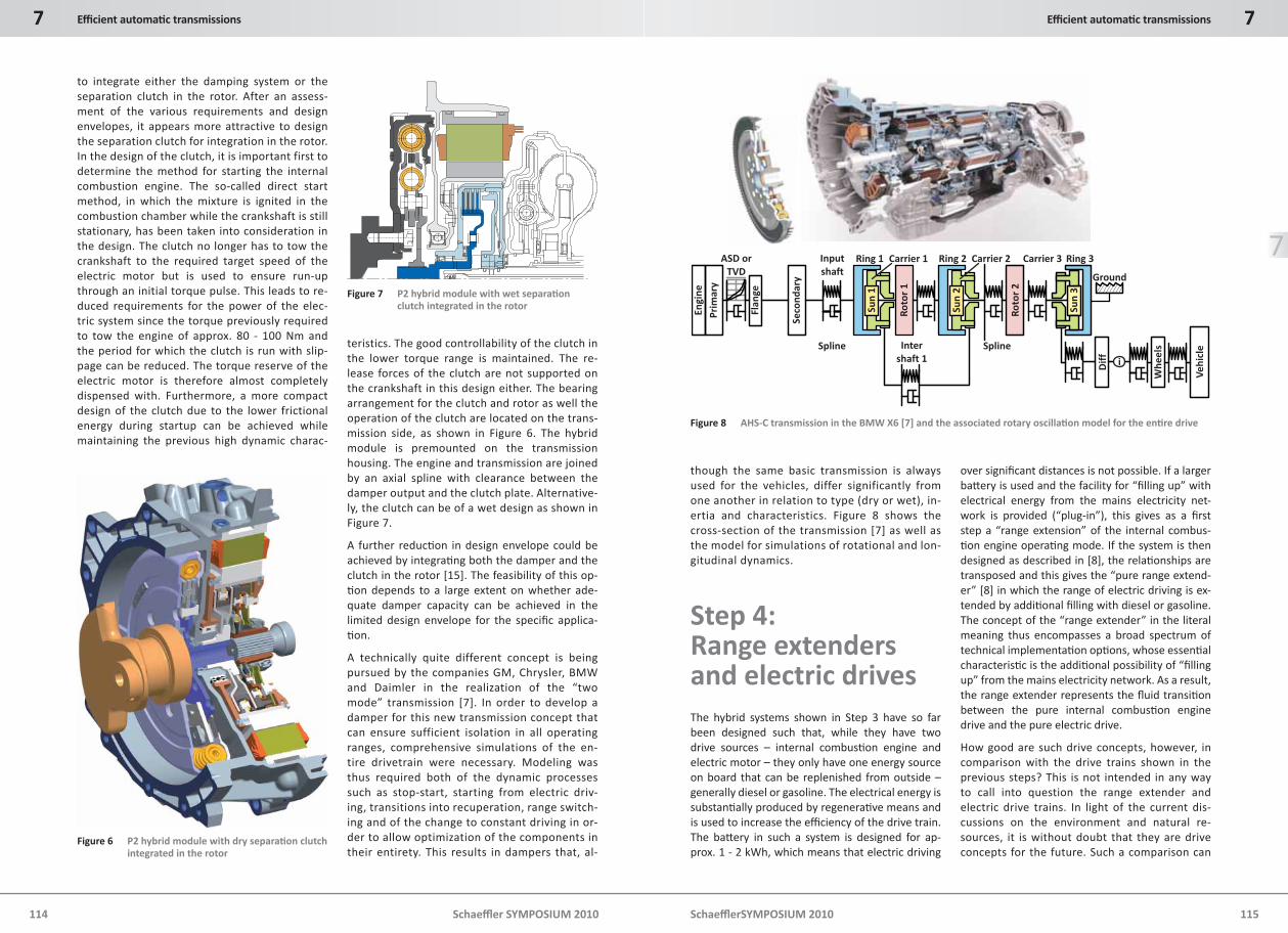
Figure 5 shows the cross-section of the hybrid module with the flex plate as the linkage for the converter of the 8 speed automatic transmis-sion.
For the development of the next generation P2 hybrid, one of the most important requirements is a further reduction in the space required for the complete system. In principle, it is possible
Figure 4 Double row arc spring damper integrated in the rotor for P1 hybrid
Figure 5 P2 hybrid module of the VW Touareg Hybrid
Schaeffl er SYMPOSIUM 2010
7 Effi cient automati c transmissions
114 Schaeffl erSYMPOSIUM 2010 115
7Effi cient automati c transmissions
7
to integrate either the damping system or the separation clutch in the rotor. After an assess-ment of the various requirements and design envelopes, it appears more attractive to design the separation clutch for integration in the rotor. In the design of the clutch, it is important first to determine the method for starting the internal combustion engine. The so-called direct start method, in which the mixture is ignited in the combustion chamber while the crankshaft is still stationary, has been taken into consideration in the design. The clutch no longer has to tow the crankshaft to the required target speed of the electric motor but is used to ensure run-up through an initial torque pulse. This leads to re-duced requirements for the power of the elec-tric system since the torque previously required to tow the engine of approx. 80 - 100 Nm and the period for which the clutch is run with slip-page can be reduced. The torque reserve of the electric motor is therefore almost completely dispensed with. Furthermore, a more compact design of the clutch due to the lower frictional energy during startup can be achieved while maintaining the previous high dynamic charac-
teristics. The good controllability of the clutch in the lower torque range is maintained. The re-lease forces of the clutch are not supported on the crankshaft in this design either. The bearing arrangement for the clutch and rotor as well the operation of the clutch are located on the trans-mission side, as shown in Figure 6. The hybrid module is premounted on the transmission housing. The engine and transmission are joined by an axial spline with clearance between the damper output and the clutch plate. Alternative-ly, the clutch can be of a wet design as shown in Figure 7.
A further reducti on in design envelope could be achieved by integrati ng both the damper and the clutch in the rotor [15]. The feasibility of this op-ti on depends to a large extent on whether ade-quate damper capacity can be achieved in the limited design envelope for the specifi c applica-ti on.
A technically quite different concept is being pursued by the companies GM, Chrysler, BMW and Daimler in the realization of the “two mode” transmission [7]. In order to develop a damper for this new transmission concept that can ensure sufficient isolation in all operating ranges, comprehensive simulations of the en-tire drivetrain were necessary. Modeling was thus required both of the dynamic processes such as stop-start, starting from electric driv-ing, transitions into recuperation, range switch-ing and of the change to constant driving in or-der to allow optimization of the components in their entirety. This results in dampers that, al-
though the same basic transmission is always used for the vehicles, differ significantly from one another in relation to type (dry or wet), in-ertia and characteristics. Figure 8 shows the cross-section of the transmission [7] as well as the model for simulations of rotational and lon-gitudinal dynamics.
Step 4: Range extenders and electric drivesThe hybrid systems shown in Step 3 have so far been designed such that, while they have two drive sources – internal combusti on engine and electric motor – they only have one energy source on board that can be replenished from outside – generally diesel or gasoline. The electrical energy is substanti ally produced by regenerati ve means and is used to increase the effi ciency of the drive train. The batt ery in such a system is designed for ap-prox. 1 - 2 kWh, which means that electric driving
over signifi cant distances is not possible. If a larger batt ery is used and the facility for “fi lling up” with electrical energy from the mains electricity net-work is provided (“plug-in”), this gives as a fi rst step a “range extension” of the internal combus-ti on engine operati ng mode. If the system is then designed as described in [8], the relati onships are transposed and this gives the “pure range extend-er” [8] in which the range of electric driving is ex-tended by additi onal fi lling with diesel or gasoline. The concept of the “range extender” in the literal meaning thus encompasses a broad spectrum of technical implementati on opti ons, whose essenti al characteristi c is the additi onal possibility of “fi lling up” from the mains electricity network. As a result, the range extender represents the fl uid transiti on between the pure internal combusti on engine drive and the pure electric drive.
How good are such drive concepts, however, in comparison with the drive trains shown in the previous steps? This is not intended in any way to call into question the range extender and electric drive trains. In light of the current dis-cussions on the environment and natural re-sources, it is without doubt that they are drive concepts for the future. Such a comparison can
Figure 6 P2 hybrid module with dry separati on clutch integrated in the rotor
Figure 7 P2 hybrid module with wet separati on clutch integrated in the rotor
i
En
gin
e
Pri
ma
ry
Fla
ng
e
Se
con
da
ry
Su
n1
Su
n2
Su
n3
Dif
f
Wh
ee
ls
Ve
hic
le
ASD or
TVD
Input
shaft
Spline
Ring 1
Ro
tor
1
Carrier 1 Ring 2
Ro
tor
2
Carrier 2 Ring 3Carrier 3
Ground
SplineInter
shaft 1
Figure 8 AHS-C transmission in the BMW X6 [7] and the associated rotary oscillati on model for the enti re drive
Schaeffl er SYMPOSIUM 2010
7 Effi cient automati c transmissions
116 Schaeffl erSYMPOSIUM 2010 117
7Effi cient automati c transmissions
7
give an impression, however, as to how quickly such concepts can be implemented and on which factors this will depend. The three criteria that should be used to give at least an approximate answer to the question are efficiency, CO2 emis-sions and costs. The effects due to recuperation are not taken into consideration here since this effect can be assumed to be equivalent in hybrid systems with and without plug-in operation. The cost comparison is only prepared in general terms on the basis of published data.
Effi ciency comparison of internal combusti on engine and electric drivesThe following analyses were carried out for various classes of vehicles. As an example, the results are shown here for a vehicle of the lower medium-size category.
For the internal combustion engine drive, a su-percharged 0.7 l 3-cylinder gasoline engine with turbocharging and power rating of 70 kW in conjunction with a manual 5 speed transmis-sion is used. No account is taken in the com-parative studies of the losses in the transmis-sion or the losses in the transmission for the electric motor described below, since these can
be assumed to be of equal magnitude. The ef-ficiency of power provision efficiency for gaso-line fuels varies widely in the technical litera-ture between 6 and 18 %. In the comparisons shown below, this is assumed to be a standard value of 10 %.
The map for the electric vehicle is generated by an electric motor as a synchronous machine with continuous excitation including the elec-tronic performance system. Torque is transmit-ted to the wheels via a single speed transmis-sion with a ratio of 7 that is assumed, like the internal combustion engine drive, to be free of losses. The efficiency of the energy reservoir is taken into consideration as constant for the charging process (slow overnight charging) and for discharging from the loss model in accor-dance with the electric power rating. The pow-er provision efficiency for electrical energy from the public network is assumed, on the ba-sis of the value applicable to Germany in 2008 [9], to be 38 %.
In order to illustrate in which operating ranges the efficiency advantages of the specific concept lie, the two maps are overlaid in a differential map (Figure 9). It can then be seen that the ad-vantage of the electric vehicle is lower by 2 - 5 % over a very wide area of the map. The advantag-es of the electric drive are only significant
at very low power ratings. It can also be seen for operating points relevant to the cycle (NEDC constant driving: red, NEDC ac-celerating: blue) that there is no significant difference between the drives. On the ba-sis of these relatively small advantages of an electric vehicle, the propagation of such drives is rather unlikely.
If the power provision effi ciency of electrical energy is altered, the dominant infl uence of this value on the map becomes apparent. For
2020, a value of 45 % is forecast for Germany. This gives a corre-sponding shift in favor of the electric vehicle (Figure 10). At most op-erati ng points, the ad-vantages are now more than 7 %.
The comparison be-comes even clearer if it is assumed that the ef-fi ciency is that of a combined-cycle power plant (cogenerati on unit with combined heat and power gen-erati on) which is ap-proximately 60 %, thus taking account of dis-tributi on losses a fur-ther 10 % bett er than the power plant effi ciency that forms the basis of Figure 10. This comparison is of decisive impor-tance for the future of the internal combusti on engine, since the questi on of whether fuel is de-rived from fossil or renewable sources becomes irrelevant in the comparison of internal the com-busti on engine drive and electric drive. From the pure perspecti ve of effi ciency and CO
2 emissions,
the burning of fuel in cogenerati on units and its conversion into electrical energy is the bett er so-luti on.
Comparison of CO2 emissions from internal combusti on engine and electric drives
When the two drives are compared on ana-logous terms in rela-tion to CO2 emissions, this already gives a clear advantage to the electric vehicle. The provision of elec-trical energy is calcu-lated on the basis of the value applicable to Germany in 2008 of 590 gCO2/kWh [9]. Over a large area of the map, the ad-vantage is approx. 20 %, while at the lower constant driv-ing points in the NEDC it is up to 38 % (Fig-ure 11).
1800 ΔΔηη in %
1600 10
14005
1200
0
1000
- 5800
600 -10
400- 15
200
- 200
0 20 40 60 80 100 120
Co
mb
us
Co
mb
ust
ion
en
gin
eti
on
en
gin
e
be
be
tttte
re
r
E-d
riv
E-d
riv
ee
be
be
tttte
re
r
Dri
ve
torq
ue
inN
m
Vehicle speed in km/h
Figure 9 Eta diff erenti al map for vehicles with internal combusti on engine drive and electric motor drive with a power provision effi ciency for electricity of 38 % for 2008 [9]
1800
1600 10
14005
1200
0
1000
- 5800
600 - 10
400- 15
200
- 200
0 20 40 60 80 100 120
ΔΔηη in %
Dri
ve
torq
ue
inN
m
Vehicle speed in km/h
Co
mb
us
Co
mb
ust
ion
en
gin
eti
on
en
gin
e
be
be
tttte
re
r
E-d
riv
E-d
riv
ee
be
be
tttte
re
r
Figure 10 Eta diff erenti al map for vehicles with internal combusti on engine drive and electric motor drive with a power provision effi ciency for electricity of 45 % as forecast for 2020
00 20 40 60 80 100 120
1800
1600
1400
1200
1000
800
600
400
200
40
20
0
- 20
- 40
- 80
- 60
ΔΔ CO in %2
Vehicle speed in km/h
Dri
ve
torq
ue
inN
m
E-d
riv
E-d
riv
ele
sse
less
CCOO
em
issi
on
se
mis
sio
ns
22
Co
mb
us
Co
mb
ust
ion
en
gin
eti
on
en
gin
e
less
Co
less
Co
em
issi
on
se
mis
sio
ns
22
Figure 11 CO2 diff erenti al map for vehicles with internal combusti on engine and electric motor drives
Schaeffl er SYMPOSIUM 2010
7 Effi cient automati c transmissions
118 Schaeffl erSYMPOSIUM 2010 119
7Effi cient automati c transmissions
7
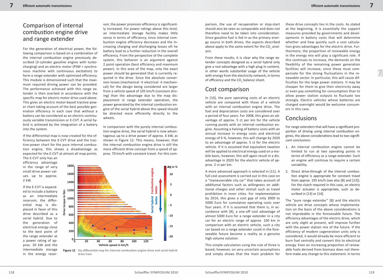
Comparison of internal combusti on engine drive and range extenderFor the generation of electrical power, the fol-lowing comparison is based on a combination of the internal combustion engine previously de-scribed (3-cylinder gasoline engine with turbo-charging) and an electric motor (PSM = synchro-nous machine with continuous excitation) to form a range extender with optimized efficiency. This module is dimensioned such that the maxi-mum required driving power can be provided. The performance achieved with this range ex-tender is then overlaid in accordance with the specific map for electric motor drive used above. This gives an electric motor-based tractive-pow-er chart taking account of the best possible gen-eration efficiency in each case that without a battery can be considered as an electric continu-ously variable transmission or E-CVT. A serial hy-brid is achieved by the integration of a battery into the system.
If the differential map is now created for the ef-ficiency between the E-CVT drive and the trac-tive-power chart for the pure internal combus-tion engine, this shows a disadvantage as expected for the E-CVT at almost all map points. The E-CVT only has an efficiency advantage in the range of very small drive power val-ues up to approx. 2 kW.
If the E-CVT is expand-ed to include a battery as an intermediate reservoir, the differ-ential map is dis-placed in favor of this drive described as a serial hybrid. Due to the generation of electrical energy close to the best point of the range extender at a power rating of ap-prox. 20 kW and the intermediate storage in the energy reser-
voir, the power provision efficiency is significant-ly increased. For power ratings above this level, an intermediate storage facility makes little sense in terms of efficiency, since internal com-bustion engine efficiency decreases and the in-creasing charging and discharging losses oft he battery lead to a further reduction in the overall efficiency. From the perspective of the complete system, this behavior is an argument against 2 point operation (best efficiency and maximum power). In this area of the map, only the exact power should be generated that is currently re-quired in the drive. Since the absolute conver-sion losses (mechanical → electrical → mechani-cal) for the design being considered are larger from a vehicle speed of 105 km/h (constant driv-ing) than the advantage due to the map dis-placement in range extender operation, the power generated by the internal combustion en-gine of the serial hybrid above this speed should be directed more efficiently directly to the wheels.
In comparison with the purely internal combus-tion engine drive, the serial hybrid is now advan-tageous up to a drive power of approx. 6 kW, as shown in Figure 12. This means, however, that the internal combustion engine drive is still the more efficient drive concept from a speed of ap-prox. 70 km/h with constant travel. For this com-
parison, the use of recuperation or stop-start should also be seen as comparable and does not therefore need to be taken into consideration. Since gasoline fuel is fed in as the primary ener-gy source in both drives, the aspects described above apply to the same extent for the CO
2 anal-ysis.
From these results, it is clear why the range ex-tender concepts designed as a serial hybrid only give a real advantage with a high plug-in content, in other words substanti al usage of the vehicle with energy from the electricity network, in terms of effi ciency and the CO2 balance sheet.
Cost comparisonIn [10], the pure operating costs of an electric vehicle are compared with those of a vehicle with an internal combustion engine drive. The fuel and depreciation costs are considered over a period of four years. For 2008, this gives an ad-vantage of approx. 5 ct per km for the vehicle running purely with an internal combustion en-gine. Assuming a halving of battery costs with an annual increase in energy costs and electrical energy of 6 %, however, this will change by 2020 to an advantage of approx. 5 ct for the electric vehicle. If it is assumed that equivalent taxation will be applied to electrical energy used on a mo-bile basis, however, this will again result in a dis-advantage in 2020 for the electric vehicle of ap-prox. 2 ct per km.
A more advanced approach is selected in [11]. A full cost assessment is carried out in this case on a “maneuverable city car” that takes account of additional factors such as willingness on addi-tional charges and other stimuli such as travel prohibition in inner cities. For implementation by 2014, this gives a cost gap of only 3000 to 5000 Euro for cumulative operating costs over four years. If it is assumed that there is, in ac-cordance with [8], a one-off cost advantage of almost 5000 Euro for a range extender in a city car for an electric range of approx. 100 km in comparison with an electric vehicle, such a city car based on a range extender could in the fore-seeable future become a reality as a genuine high volume solution.
This simple calculation using the rule of three is based, however, on very uncertain assumptions and simply shows that the main problem for
1800
1600 10
14005
1200
0
1000
- 5800
600 - 10
400- 15
200
- 200
0 20 40 60 80 100 120
ΔΔηη in %
Dri
ve
torq
ue
inN
m
Vehicle speed in km/h
Co
mb
us
Co
mb
ust
ion
en
gin
eti
on
en
gin
e
be
be
tttte
re
r
Se
ria
lh
Se
ria
lh
yb
rid
yb
rid
be
be
tttte
re
r
Figure 12 Eta diff erenti al map for internal combusti on engine drive and serial hybrid drive train
these drive concepts lies in the costs. As stated at the beginning, it is essentially the support measures provided by governments and devel-opments in battery costs that will determine whether and how quickly such a cost calcula-tion gives advantages for the electric drive. Fur-thermore, the proportion of renewable energy in the energy mix will play a significant role. If this continues to increase, the demands on the flexibility of the remaining power generation facilities will increase, since these must com-pensate for the strong fluctuations in the re-newable sector. In particular, this will cause dif-ficulties for the large power stations. It may be cheaper for them to give their electricity away or even pay something for consumption than to allow power station outputs to fluctuate too strongly. Electric vehicles whose batteries are charged overnight would be welcome consum-ers in this case.
ConclusionsFor range extenders that will have a signifi cant pro-porti on of driving using internal combusti on en-gines, the above considerati ons lead to two signifi -cant conclusions:
1. An internal combustion engine cannot be limited to run at two operating points in terms of efficiency as a range extender. Such an engine will continue to require a certain variability.
2. Direct drive-through of the internal combus-ti on engine is appropriate for constant travel from approx. 105 km/h (see also [8] and [12]). For the clutch required in this case, an electric motor actuator is appropriate, such as de-scribed in [13] or [14].
The “pure range extender” [8] and the electric vehicle are drive concepts whose implementa-tion on the basis of the above considerations is not improbable in the foreseeable future. The efficiency advantages of the electric drive, which are only slight at present, will improve further with the power station mix of the future. If the efficiency of modern cogeneration units only is considered, it would already be more efficient to burn fuel centrally and convert this to electrical energy. Even an increasing proportion of renew-able fuels derived from biomass does not there-fore make any change to this statement. In terms
Schaeffl er SYMPOSIUM 2010
7 Effi cient automati c transmissions
120 Schaeffl erSYMPOSIUM 2010 121
7Effi cient automati c transmissions
7
of CO2 analysis, the situation is even clear-er. In this case, the electric drive has clear advantages even on current analysis that will only increase in future. Essentially, it is the costs and perfor-mance capability of batteries and the as yet incomplete infra-structure that are still an obstacle to the electric drive.
In order to allow fur-ther investigation of these drive concepts, two test vehicles were built at Schaef-fler, the “Schaeffler Plug-in Hybrid” based on an Opel Corsa and the “Schaeffler Elec-tric Vehicle” based on a Skoda Octavia shown in [18].
The drive concept of the Schaeffler Hybrid is di-vided into a hybrid drive on the front axle and a pure electric drive for the rear axle. On the front axle of the vehicle, a synchronous machine with continuous excitation can be coupled by means of an automated 2 speed step transmission. This electric motor is arranged on a parallel axis and connected to the transmission input shaft via a chain. A 3-cylinder gasoline engine can be con-nected by means of an automated separation clutch. The rear wheels are each driven by a wheel hub motor with continuous excitation. As a result, the front axle can have a parallel hybrid drive and when the transmission is in neutral a serial hybrid drive is possible as a range extender in combination with the electric drive on the rear axle. When both operating modes are acti-vated at the same time, all-wheel drive can also be presented. Furthermore, the wheel hub mo-tors allow filling up of tractive power during gearshifts. The total wheel torque during electric driving is a maximum of 2100 Nm. Figure 13 shows the complete drive and an example of the operating strategy for a low charge state of the energy reservoir.
The focus will now be on the following key devel-opment issues:
acti ve vibrati on damping
fi lling up of tracti ve power by electric motor during gearshift
behavior of the “range extender operati on”
acousti cs in electric driving
drivability of unsprung masses in wheel hub motors or drive close to the wheel
distributi on of tracti ve power to the front and rear axle
assessment of actual batt ery capacity
acti ve torque vectoring to the front and rear axle
A further point to be analyzed with the aid of the concept vehicle is the question of the necessity of a 2 speed transmission for the electric drive. At a constant gearshift speed, simulations show a consumption advantage (as energy removal from the battery) of 3 %, with an advantage of up to 6.4 % with optimum map gearshift without gearshift hysteresis, depending on the possible transmission ratio spread. This is in turn deci-
sively dependent on the following influencing factors:
maximum wheel torque
total drive power
maximum vehicle speed
the necessary gearshift hysteresis
power drop of the electric motor in the maximum speed range
In addition to influence as described above on energy consumption, the transmission is also the value around which the electric motor can be downsized and the reduced costs for the electric system can be weighed up in compari-son with the additional costs for the second gear.
For vehicles in the A/B segment with current typi-cal driving characteristi cs and a drive power rati ng of 30 - 80 kW, the use of a 2 speed powershift transmission appears sensible and economically favorable. Simple structures were sought that could be used to fulfi ll the demands on the trans-mission as economically as possible. The very good controllability of the electric motor and its short-
term overload capability are preconditi ons for the design of the transmission, as shown in Figure 14.
The housing comprises a planet set on the input side whose crown wheel is either locked against the housing by means of a brake or is locked up by means of a wet clutch. In conjuncti on with a con-stant spur gear output step, this gives total rati os of 13.5 and 5.6 for a vehicle with a drive power rat-ing of 70 kW. The powershift is controlled exclu-sively via the clutch. The brake is designed as an economical “black/white” actuator. The diff eren-ti al is represented as a lightweight diff erenti al of a planetary design [19], giving signifi cant design en-velop advantages in the total length of the drive.
SummaryIn light of the demands for low consumpti on and reduced CO2 emissions with a simultaneously growing requirement for increased comfort, it is to be expected that market shares for automati c transmissions will show disproporti onately high growth in future. The signifi cant preconditi ons in case are further improvements in effi ciency, spread, mass, design envelope and costs. With concepts for dry and wet double clutch transmis-sion systems, eff ecti ve damper soluti ons for auto-mati c converters and new ideas for CVTs, LuK has developed the appropriate components to allow the necessary objecti ves to be achieved in the vari-ous transmission technologies.
In order to achieve further reducti ons in consump-ti on and CO2 emissions, the stop-start systems will succeed over wide areas. For future automati c transmissions, this gives rise to the requirements for operati on independent of engine operati on during standsti ll and the ability to restart the en-gine in the shortest possible ti me. To this end, LuK has developed various system soluti ons for double clutch transmissions, CVT and also planetary auto-mati c transmissions.
The double clutch transmission with electric motor actuati on off ers ideal conditi ons for hybridizati on. Such a vehicle was built by LuK as a mild hybrid and shown at the LuK Symposium 2006. The concept is now being pursued in several projects as a full hy-brid, with the fi rst volume applicati ons expected from 2013. Alternati ve full hybrid systems are the P2 hybrid that is entering producti on at VW on the
1
24
3
56
7
1
2
4
3
5
6
7
0
0 50 100 130
100 %Parallel +
boost
Parallel + load
Electric drive
Recuperation
Serial + load
Serial + boost
Loa
din
%
Vehicle speed in km/h
3-Cylinder gasoline
Automated clutch
2-speed transmission
Central E-motor
In wheel E-motor
Power electronics
Battery
Figure 13 Concept vehicle Schaeffl er Hybrid
Figure 14 2 speed powershift transmission for electric vehicles
Schaeffl er SYMPOSIUM 2010
7 Effi cient automati c transmissions
122 Schaeffl erSYMPOSIUM 2010 123
7Effi cient automati c transmissions
7
basis of the Colorado platf orm in 2010 with a sepa-rati on clutch system from LuK, and the power-split two mode transmission in which dampers from LuK are used to fulfi ll the challenging isolati on functi ons.
A comparison of internal combusti on engine and electric motor drives shows that the electric drive already represents the clearly bett er drive type in relati on to CO2 emissions. In terms of effi ciency, the result of the comparison is not so clear but the developments in power stati on technologies show that the electric drive will also be the bett er alter-nati ve in future in many operati ng ranges in this respect. In light of the intensifying public discus-sions of environmental and energy matt ers, it must therefore be expected that the proporti on of plug-in technologies will show strong growth. The only real hurdle to the rapid spread of these drive con-cepts currently lies in the inadequately low energy density and the excessively high costs of batt eries. Current cost forecasts and developments towards “open” batt ery systems show, however, that this will change by 2020. For this reason, the Schaeffl er Hybrid Vehicle and Schaeffl er Electric Vehicle were built at Schaeffl er as a development platf orm for new drive concepts. Such complete systems are being used at Schaeffl er as a basis for developing the transmission and electric motor technologies for future mobility.
Literature[1] Liebl, J.: Electric mobility – the next step at
BMW Effi cientDynamics?, 8th Internati on-al CTI-Symposium Innovati ve Automoti ve Transmissions, 2009
[2] Pollak, B.: How much transmission is need-ed for electrifi cati on or hybridisati on?, 8th Internati onal CTI-Symposium Innovati ve Automoti ve Transmissions, 2009
[3] Vafi dis, C.: FPT’s high torque density dual dry clutch transmission (HTD-DDCT), 8th Internati onal CTI-Symposium Innovati ve Automoti ve Transmissions, 2009
[4] Bek, M.; Schiele, P.: Hydraulic Impulse Stor-age – How ZF Automati c Transmissions Contribute to CO2 Reducti on, 29th Interna-ti onal Vienna Motor Symposium, 2008
[5] Küpper, K.; Seebacher, R.; Werner, O.: Think Systems – Soft ware by LuK, 7th LuK Sympo-sium, 2002
[6] Reik, W.; Reitz, D., Vornehm, M.: World of Hybrids, 8th LuK Symposium, 2006
[7] Braun, H.; Krauß, M.; Ratt ei, F.; Bohne, W.; Engelmann, M.; Deuke, U.; Di Pierro, M.: The Full Hybrid Powertrain for BMW Ac-ti veHybrid X6, ATZ 11/2009
[8] Fischer, R.; Fraidl, G.; Hubmann, C.; Kapus, P.; Kunzemann, R.; Siff erlinger, B.; Beste, F.: Range Extender Module – Enabler for Elec-tric Mobility, ATZ 10/2009
[9] FG I 2.5: Strommix 2007, Umweltbundesamt
[10] Diez, W.: Zurück ind die Zukunft ? – Hochs-pannung! Das Comeback des Elektroant-riebes, Automoti ve Agenda 01, 2008
[11] McKinsey & Company: Roads toward a low-carbon future: Reducing CO2 emissions from passenger vehicles in the global road transportati on system, March 2009
[12] Erjawetz, K.: Drives for electric vehicles and range extended electric vehicle, 8th Inter-nati onal CTI-Symposium Innovati ve Auto-moti ve Transmissions, 2009
[13] Kimmig, K.; Bührle, P.; Henneberger, K.; Eh-rlich, M.; Rathke, G.; Marti n, J.: Success with effi ciency and comfort – The dry dou-ble clutch has become established on the automati c transmission market, 9th Schaeffl er Symposium, 2010
[14] Müller, B.; Kneissler, M.; Gramann, M.; Esly, N.; Daikeler, R.; Agner, I.: Smaller, more fl ex-ible, more intelligent – Advance develop-ment components for double-clutch trans-missions, 9th Schaeffl er Symposium, 2010
[15] Lindemann, P.; Krause, T.; Swank, M.; George, P.; Hemphill, J.; Marathe, B.: Torque Converters – Launching over new challeng-es, 9th Schaeffl er Symposium, 2010
[16] Englisch, A.: CVT – high value and high per-formance, 9th Schaeffl er Symposium, 2010
[17] Zink, M.; Hausner, M.: LuK Clutch Systems and Torsional Dampers – Key Elements for Effi cient Drive Trains, 9th Schaeffl er Sym-posium, 2010
[18] Smetana, T.; Biermann, T.; Höhn, B.-R.; Kur-th, F.: Schaeffl er acti ve eDiff erenti al – The acti ve diff erenti al for future drive trains, 9th Schaeffl er Symposium, 2010
[19] Biermann, T.; Smetana, T.; Höhn, B.-R.; Kurth, F.: Schaeffl er lightweight diff eren-ti als – A family of diff erenti als reduced in space and weight, 9th Schaeffl er Sympo-sium, 2010