GEBERIT DRAINAGE SYSTEMS GEBERIT HDPE ABOVE GROUND DRAINAGE SYSTEM
This Agrément Certificate Product Sheet(1) relates to the The Geberit HDPE Above Ground Drainage System, comprising pipes, adaptors and fittings for the conveyance of surface water and sewage in domestic, commercial and public buildings.
(1) Hereinafter referred to as ‘Certificate’.
CERTIFICATION INCLUDES:
• factors relating to compliance with Building Regulations where applicable
• factors relating to additional non-regulatory information where applicable
• independently verified technical specification • assessment criteria and technical investigations • design considerations • installation guidance • regular surveillance of production • formal three-yearly review.
KEY FACTORS ASSESSED
Strength — the system has adequate strength to resist the loads associated with installation and subsequent use (see section 6).
Performance of joints — the connections between the pipes and fittings are watertight under normal service conditions (see section 7).
Flow characteristics — the system using the pipes, couplings and fittings will have satisfactory flow characteristics (see
section 8).
Resistance to elevated temperatures — the system has adequate resistance to the temperatures likely to be found in
domestic waste water (see section 10).
Durability — the system will have a service life in excess of 50 years (see section 13).
The BBA has awarded this Certificate to the company named above for the system described herein. This system has been assessed by the BBA as being fit for its intended use provided it is installed, used and maintained as set out in this Certificate
On behalf of the British Board of Agrément
Date of First issue: 28 October 2019
Originally certificated under BBA Certificate 92/2796
Paul Valentine Technical Excellence Director
Claire Curtis-Thomas Chief Executive
The BBA is a UKAS accredited certification body – Number 113. The schedule of the current scope of accreditation for product certification is available in pdf format via the UKAS link on the BBA website at www.bbacerts.co.uk Readers are advised to check the validity and latest issue number of this Agrément Certificate by either referring to the BBA website or contacting the BBA direct.
Any photographs are for illustrative purposes only, do not constitute advice and should not be relied upon.
British Board of Agrément Bucknalls Lane Watford Herts WD25 9BA
In the opinion of the BBA, the The Geberit HDPE Above Ground Drainage System, if installed, used and maintained in accordance with this Certificate, can satisfy or contribute to satisfying the relevant requirements of the following Building Regulations (the presence of a UK map indicates that the subject is related to the Building Regulations in the region or regions of the UK depicted):
The Building Regulations 2010 (England and Wales) (as amended)
Requirement: H1 Foul water drainage Comment: The system will convey the flow of foul water and minimise the risk of blockages
or leakage. See sections 4.1, 7 and 8.1 of this Certificate. Requirement: H3(1) Rainwater Drainage Comment: The system will convey the flow of rain water and minimise the risk of blockages
or leakage. See sections 4.1, 7 and 8.1 of this Certificate. Regulation: 7 Materials and workmanship (applicable to Wales only) Regulation: 7(1) Materials and workmanship (applicable to England only) Comment: The system is acceptable. See section 13 and the Installation part of this
Certificate.
Regulation: 7(2) Materials and workmanship (applicable to England only) Comment: The use of the system is restricted by this Regulation. See section 11.1 of this
Certificate.
The Building (Scotland) Regulations 2004 (as amended)
Regulation: 8(1)(2) Durability, workmanship and fitness of materials Comment: The system complies with the requirements of this Regulation. See sections 12 and
13 and the Installation part of this Certificate. Regulation: 9 Building standards applicable to construction Standard: 3.6(a) Surface water drainage Comment: The system will satisfy the relevant requirements of this Standard, with reference
to clauses 3.6.2(1)(2) and 3.6.8(1)(2). See sections 4.1, 7 and 8.1 of this Certificate.
Standard: 3.7(b)(c) Waste water drainage Comment: The system will satisfy the relevant requirements of this Standard, with reference
to clauses 3.7.1(1)(2), 3.7.10(1), 3.7.11(2). See section 4.1, 7 and 8 of this Certificate.
Standard: 7.1(a)(b) Statement of sustainability Comment: The system can contribute to meeting the relevant requirements of Regulation 9,
Standards 1 to 6 and therefore will contribute to a construction meeting a bronze level of sustainability as defined in this Standard.
Regulation: 12 Building standards applicable to conversions Comment: All comments given for the system under Regulation 9, Standards 1 to 6 also apply
to this Regulation, with reference to clause 0.12.1(1)(2), and Schedule 6(1)(2). (1) Technical Handbook (Domestic).
(2) Technical Handbook (Non-Domestic).
The Building Regulations (Northern Ireland) 2012 (as amended)
Regulation: 23(a)(i)(iii)b(i) Fitness of materials and workmanship Comment: The system is acceptable. See section 13 and the Installation part of this
Certificate.
Page 3 of 17
Regulation: 79 Drainage systems Comment: The system is acceptable. See sections 4.1, 7 and 8.1 of this Certificate. Regulation: 80 Sanitary pipework Comment: The system satisfies the relevant requirements of this Regulation. See section 4.1
of this Certificate. Regulation: 82 Rainwater drainage Comment: The system is acceptable. See sections 4.1, 6, 7 and 8.1 of this Certificate.
Construction (Design and Management) Regulations 2015 Construction (Design and Management) Regulations (Northern Ireland) 2016 Information in this Certificate may assist the client, designer (including Principal Designer) and contractor (including Principal Contractor) to address their obligations under these Regulations. See sections: 3 Delivery and site handling (3.5) and 5 Practicability of installation (5.2) of this Certificate.
Additional Information
NHBC Standards 2019 In the opinion of the BBA, the The Geberit HDPE Above Ground Drainage System, if installed, used and maintained in accordance with this Certificate, can satisfy or contribute to satisfying the relevant requirements in relation to NHBC Standards, Chapter 8.1 Internal services.
Technical Specification
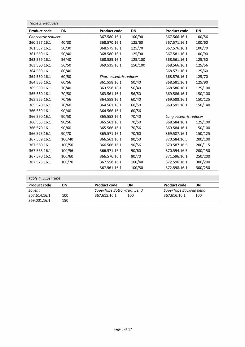
1 Description The Geberit HDPE Above Ground Drainage System comprises a range of pipes and fittings (reducers, bends, Sovent, SuperTube elements, branches, branchballs, access pipes, ends, flanges, caps and others) as listed in Tables 1 to 12. 1.2 The pipes are black and normally supplied in 5 m lengths but can be produced in suitable lengths to form prefabricated pipeline elements. Pipes with a nominal diameter up to 160 mm comply with series S12.5, and those of 200, 250 and 315 mm (for application area code “B” only) with series S16, as defined in BS EN 1519-1 : 2019. S12.5 pipes 200, 250 and 315 mm are marked as ‘Geberit HDPE Pipe PN4’ and are used in siphonic drainage systems. 1.3 Lip-seal sockets (see Table 9.2) require lower push forces compared to ring seal sockets and provide prolonged connection length. They enable use of electrofusion coupling without separate prolonged version. 1.4 There are seven methods available for joining the pipes/fittings (see Figure 1). These are: • butt welding (see Figure 1a) — utilising Geberit hot-plate type KSS160 or KSS200, with lights indicating when
temperature reached • electrofusion welding (see Table 8.1 and Figure 1b) — Geberit welding apparatus (or other approved device, contact
Geberit for further advice) reference ESG160 must be used for pipes 40 to 160mm diameter and reference ESG315 for pipes 200 to 315mm diameter. Coupling with integrated heat fuse cuts out at set temperature
• socket joint (see Table 9.2 and Figure 1c) — for butt welding to a pipe or fitting spigot • screw-threaded joints (see Table 9.3 and Figure 1d) — consists of a male-threaded spigot which must be butt
welded to the pipe or fitting, an EPDM compression seal, a nylon bush and a polyethylene female-threaded cap • expansion socket (see Table 9.2 and Figure 1e) — for welding to pipe or fitting spigots at one end and incorporating
a ring-seal joint at the other. They permit longitudinal movement between adjacent pipes • flange joint threaded joint (see Table 11 and Figure 1f) — incorporates two flange adaptors which must be butt
welded to the pipe/spigots to be joined, an EPDM flange seal, two cast iron flange plates and the appropriate number of galvanized steel bolts and washers
Page 4 of 17
• compression fitting butt welded to pipe for adaption to PVC-U (see Figure 1g) — consisting of a male-threaded spigot [which must be butt welded to the high-density polyethylene (HDPE) pipe or fitting], an EPDM compression seal, a nylon brush and a polyethylene female thread cap. PVC-U pipe inserts into compression joints
• adaptor clamping connector (see Figure 1h) — stainless steel pipe clamp and EPDM seal, incorporating two allen head screws to tighten the joint. The stainless-steel support ring is within the HDPE part.
Figure 1 Joint types
1.5 For use with the system, but outside the scope of this Certificate, are fixings and brackets for securing pipes.
2 Manufacture 2.1 The HDPE pipes are extruded from batch mixed raw materials and cut to length. The fittings are injection moulded, thermoformed or welded extrusions. Segment bends are manufactured from HDPE pipe with butt welded joints. Seals are manufactured from EPDM polymer. 2.2 As part of the assessment and ongoing surveillance of product quality, the BBA has:
agreed with the manufacturer the quality control procedures and product testing to be undertaken
assessed and agreed the quality control operated over batches of incoming materials
monitored the production process and verified that it is in accordance with the documented process
evaluated the process for management of nonconformities
checked that equipment has been properly tested and calibrated
undertaken to carry out the above measures on a regular basis through a surveillance process, to verify that the specifications and quality control operated by the manufacturer are being maintained.
2.3 The management systems of Geberit Ltd (IT), Geberit International AG (CH), Geberit Vertriebs GmbH (DE) and Geberit Österreich (AT) have been assessed and registered as meeting the requirements of BS EN ISO 9001 : 2015 by SQS (Certificate H20644). The management system for Shanghai Longda Plastic Technology Inc. was assessed and registered as meeting the requirements of BS EN ISO 9001 : 2015 by Beijing Zhonfg Da Hua Yuan Certification Centre (Certificate ANAB15Q20502R4M).
3 Delivery and site handling 3.1 Each pipe is marked with the manufacturer’s code, external diameter, wall thickness and BS EN 1519-1 : 2019 identification markings. Fittings are marked with nominal diameter without reference to thickness. 3.2 Pipes are supplied unprotected and should be stored in stacks not more than 1 m high and away from heat sources to avoid distortion. 3.3 The BBA logo incorporating the number of this Certificate is stamped onto all sales invoices. 3.4 When long-term storage is envisaged, the system components must be protected from direct sunlight, preferably under cover. They should not be stored near fuel bowsers, fuel tanks or other solvents to avoid potential chemical damage. 3.5 The pipes must have adequate protection against damage from site traffic. Care must be taken when handling. Extra precaution should be taken in cold conditions due to the reduction in impact strength of plastics products. 3.6 The fittings are supplied in polythene bags and, where practical, should be stored in this way until installation. Where long term storage is required, the fittings must be protected from direct sunlight.
Assessment and Technical Investigations The following is a summary of the assessment and technical investigations carried out on the The Geberit HDPE Above Ground Drainage System.
Design Considerations
4 Use
4.1 The The Geberit HDPE Above Ground Drainage System is satisfactory for use in domestic, commercial and public buildings, and in installations designed in accordance with PD CEN/TR 13801 : 2014, BS EN 12056-2 : 2000 and BS EN 12056-3 : 2000 for the conveyance of surface water and domestic sewage as is permitted to be discharged into public sewers by the Water Industry Act 1991 (England and Wales), and surface water and sewage as is permitted and defined by the Sewerage (Scotland) Act 1968 and the Water and Sewerage Services (Northern Ireland) Order 2006.
Page 11 of 17
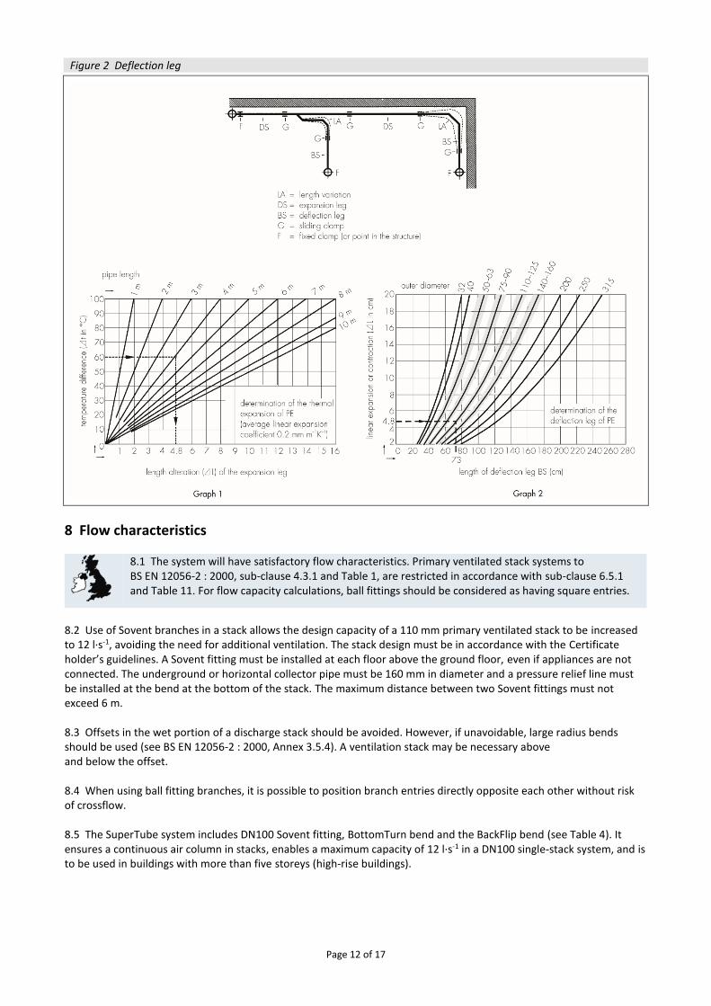
4.2 This Certificate does not cover the use of any of the system for untreated trade effluent. 4.3 The average linear expansion coefficient for Geberit pipes is 2 x 10– 4 m∙m– 1∙°C. Installations must be designed to accommodate or prevent the anticipated thermal movement as given in sections 4.4 to 4.8. 4.4 Movement of pipes can be prevented by embedding in concrete or by rigid fixings. 4.5 The adhesion between concrete and the pipes is inadequate to prevent movement. When installed within concrete floors the movement is prevented by the use of electro weld sleeves or bushes which protrude from the external surface of the pipe. These fittings must be used near each branch connection. Ring-seal sockets should not be embedded in concrete. The expansion and contraction forces created by thermal movement must be accommodated by the concrete. 4.6 The forces exerted on pipe supports, anchors and the structure must be considered when rigid fixings are used. Rigid fixings are not considered suitable for pipes over 160 mm in diameter. Guidance on the load exerted on fixings is available from the Certificate holder. 4.7 Vertical and horizontal expansion can be catered for by the linear expansion socket. The linear expansion socket is designed to cope with the expansion equivalent to a 6 m run of pipe through a temperature change of 80°C and should be used in conjunction with rigid anchor fixings and sliding guide hangers as described in the Certificate holder’s Installation Guide. 4.8 Thermal movement can also be accommodated by the incorporation of a deflection leg in the system design (see Figure 2). The maximum anticipated movement is determined using Graph 1, and the length of the required deflection leg appropriate to the predicted movement is read from Graph 2. The procedure is described in the Certificate holder’s Installation Guide.
5 Practicability of installation 5.1 The system is designed to be installed by a competent general builder, plumber or contractor experienced with this type of system. The pipes and fittings are installed under normal site conditions. 5.2 The correct personal protection equipment must be used when cutting pipes using mechanically powered or manual cutters.
6 Strength 6.1 The system has adequate resistance to the impact loads to which it may be subjected during installation and in normal service conditions. 6.2 The system should be protected from impacts, for example, being dropped from a height.
7 Performance of joints
7.1 The joints, when correctly made, will not be adversely affected by thermal expansion or contraction (see sections 4.4 to 4.8).
7.2 The joints will remain watertight under conditions of pipeline movement in excess of those expected to occur in normal good drainage practice.
Page 12 of 17
Figure 2 Deflection leg
8 Flow characteristics
8.1 The system will have satisfactory flow characteristics. Primary ventilated stack systems to BS EN 12056-2 : 2000, sub-clause 4.3.1 and Table 1, are restricted in accordance with sub-clause 6.5.1 and Table 11. For flow capacity calculations, ball fittings should be considered as having square entries.
8.2 Use of Sovent branches in a stack allows the design capacity of a 110 mm primary ventilated stack to be increased to 12 l∙s-1, avoiding the need for additional ventilation. The stack design must be in accordance with the Certificate holder’s guidelines. A Sovent fitting must be installed at each floor above the ground floor, even if appliances are not connected. The underground or horizontal collector pipe must be 160 mm in diameter and a pressure relief line must be installed at the bend at the bottom of the stack. The maximum distance between two Sovent fittings must not exceed 6 m. 8.3 Offsets in the wet portion of a discharge stack should be avoided. However, if unavoidable, large radius bends should be used (see BS EN 12056-2 : 2000, Annex 3.5.4). A ventilation stack may be necessary above and below the offset. 8.4 When using ball fitting branches, it is possible to position branch entries directly opposite each other without risk of crossflow. 8.5 The SuperTube system includes DN100 Sovent fitting, BottomTurn bend and the BackFlip bend (see Table 4). It ensures a continuous air column in stacks, enables a maximum capacity of 12 l∙s-1 in a DN100 single-stack system, and is to be used in buildings with more than five storeys (high-rise buildings).
Page 13 of 17
9 Resistance to chemicals The system will be unaffected by the types and quantities of chemicals likely to be found in the effluents defined in section 4.1.
10 Resistance to elevated temperatures The system has adequate resistance to the temperatures likely to occur in the effluents defined in section 4.1.
11 Behaviour in relation to fire
11.1 The system’s components passing through a fire rated wall or floor should not be used on buildings in England that have a storey at least 18 m above ground level and contain: one or more dwellings, an institution, a room for residential purposes (excluding any room in a hostel, hotel or boarding house), student accommodation, care homes, sheltered housing, hospitals or dormitories in boarding schools.
11.2 In common with other plastic materials, the system components are combustible, and in a fire may ignite and burn. They will not result in the release of toxic gases; however, consideration should be given to the need for protective, fire resistant ducting when assessing the fire risk in a building, particularly where large quantities of piping may otherwise be exposed. 11.3 The national Building Regulations concerning the prevention of fire spread, eg by fire-stopping, must be taken into account at the design stage. 11.4 When pipes with an internal diameter greater than 40 mm are used, special attention must be taken to confirm whether or not the system has to be encased by protective shafts or isolated between separating elements.
12 Maintenance
Sections of the system can be removed and replaced. The installation must be designed so that access is provided in accordance with BS EN 12056-2 : 2000, Annex NG4.
13 Durability
In the opinion of the BBA, when used in accordance with this Certificate, the material from which the system components are manufactured will not significantly deteriorate, and the anticipated service life of the system will be in excess of 50 years.
14 Reuse and recyclability The system components contain polyethylene, which can be recycled.
Installation
15 General The The Geberit HDPE Above Ground Drainage System must be in accordance with the Certificate holder’s literature and with the guidance and recommendations for building drainage and sanitation given in BS EN 12056-5 : 2000, where appropriate.
Page 14 of 17
16 Procedure 16.1 End-to-end butt weld joints must be carried out under controlled conditions: • pipe must be cut square and clean using a pipe cutter • the welding plate must be clean • the required lateral pressure must be applied • appropriate heat-up and weld time should be used. 16.2 The welding procedure is as follows: • the face of each item is heated by lightly pressing the components against the heating plate for the correct period • clamping pressure is gradually increased to the required value and held for the specified period • clamps and jigs are available to ensure correct alignment of the joint. 16.3 Electrowelded joints using the appropriate Geberit welder must be carried out as follows: • the pipe end and sleeve must be kept dry at all times • the pipe is cut off at right-angles, deburred and cleaned • the pipe or fitting is inserted into the sleeve to the central register, the welder is connected to the sleeve and
operated in accordance with the manufacturer’s instructions. 16.4 Other types of connection components must be butt welded to the spigot to be joined in accordance with sections 16.1 and 16.2. The connection to the ongoing end is made according to the joint type: • ring-seal socket — the pipe or fitting spigot is lubricated and pushed fully into the socket • expansion socket(1) — the pipe is pushed the appropriate length into the socket, depending on the temperature at
the time of installation (see Tables 9.2 and 13) • screw-threaded fittings are connected to spigots by inserting the spigot fully into the joint and tightening the locking
collar by hand. (1) These sockets should be protected from the ingress of dirt by wrapping the joint with a felt bandage and securing with adhesive tape.
Table 13 Insertion depth for expansion sockets (mm)
Nominal diameter (mm) Temperature (oC)
-10 0 +10 +20
40-160 70 80 90 105 200-315 170 180 190 205
16.5 Pipes are secured by anchor brackets on hangers (outside the scope of this Certificate, but available from the manufacturer). The maximum spacing of the supports must be 1.2 m on vertical pipes and 0.5 m on near horizontal pipes.
Technical Investigation 17 Tests Tests were carried out on the system and its components in accordance with the relevant clauses of BS EN 1519-1 : 2019 and the results assessed to determine: Pipes
dimensional accuracy to BS EN ISO 3126 : 2005
impact resistance to BS EN ISO 3127 : 2017
longitudinal reversion to BS EN ISO 2505 : 2005
Page 15 of 17
Fittings
dimensional accuracy to BS EN ISO 3126 : 2005
effects of heating to BS EN ISO 580 : 2005
resistance to cross-flow of ball fittings
System
watertightness to BS ISO 13254 : 2017
airtightness to BS ISO 13255 : 2017
elevated temperature cycling to BS ISO 13257 : 2018
flow capacity of single stack systems incorporating Sovent DN150 and ball fittings
flow capacity of single stack systems incorporating Sovent DN100 and SuperTube bends
deflection of typical assemblies Material
melt-mass flow rate to BS EN ISO 1133-1 : 2011
thermal stability (OIT) to BS EN ISO 11357-6 : 2018
resistance to internal pressure to BS EN ISO 1167-1 : 2018.
18 Investigations 18.1 Data was evaluated to assess:
practicability of installation
flow characteristics
resistance to chemicals.
18.2 The manufacturing process was evaluated, including the methods adopted for quality control, and details were obtained of the quality and composition of the materials used. 18.3 A site visit was conducted to establish the ease of installation.
Page 16 of 17
Bibliography BS EN 1519-1 : 2019 Plastic piping systems for soil and waste discharge (low and high temperature) within the building structure – Polyethylene (PE) — Requirements for pipes, fittings and the system BS EN 12056-2 : 2000 Gravity drainage systems inside buildings — Sanitary pipework, layout and calculation BS EN 12056-3 : 2000 Gravity drainage systems inside buildings — Roof drainage, layout and calculation BS EN 12056-5 : 2000 Gravity drainage systems inside buildings — Installation and testing, instructions for operation, maintenance and use BS EN ISO 580 : 2005 Plastics piping and ducting systems — Injection-moulded thermoplastics fittings — Methods for visually assessing the effects of heating BS EN ISO 1133-1 : 2011 Plastics — Determination of the melt mass-flow rate (MFR) and melt volume-flow rate (MVR) of thermoplastics — Standard method BS EN ISO 1167-1 : 2018 Thermoplastics pipes, fittings and assemblies for the conveyance of fluids. Determination of the resistance to internal pressure. General method BS EN ISO 2505 : 2005 Thermoplastics pipes — Longitudinal reversion — Test methods and parameters BS EN ISO 3126 : 2005 Plastics piping systems — Plastics components — Determination of dimensions BS EN ISO 3127 : 2017 Thermoplastics pipes — Determination of resistance to external blows — Round-the-clock method BS EN ISO 9001 : 2015 Quality management systems — Requirements BS EN ISO 11357-6 : 2018 Plastics. Differential scanning calorimetry (DSC) — Determination of oxidation induction time (isothermal OIT) and oxidation induction temperature (dynamic OIT) BS ISO 13254 : 2017 Thermoplastics piping systems for non-pressure applications — Test method for watertightness BS ISO 13255 : 2017 Thermoplastics piping systems for soil and waste discharge inside buildings — Test method for airtightness of joints BS ISO 13257 : 2018 Thermoplastics piping systems for non-pressure applications — Test method for resistance to elevated temperature cycling PD CEN/TR 13801 : 2014 Plastics piping systems for soil and waste discharge (low and high temperature) within the building structure — Thermoplastics — Recommended practice for installation
Page 17 of 17
Conditions of Certification
19 Conditions 19.1 This Certificate:
relates only to the product/system that is named and described on the front page
is issued only to the company, firm, organisation or person named on the front page – no other company, firm, organisation or person may hold or claim that this Certificate has been issued to them
is valid only within the UK
has to be read, considered and used as a whole document – it may be misleading and will be incomplete to be selective
is copyright of the BBA
is subject to English Law. 19.2 Publications, documents, specifications, legislation, regulations, standards and the like referenced in this Certificate are those that were current and/or deemed relevant by the BBA at the date of issue or reissue of this Certificate. 19.3 This Certificate will remain valid for an unlimited period provided that the product/system and its manufacture and/or fabrication, including all related and relevant parts and processes thereof:
are maintained at or above the levels which have been assessed and found to be satisfactory by the BBA
continue to be checked as and when deemed appropriate by the BBA under arrangements that it will determine
are reviewed by the BBA as and when it considers appropriate. 19.4 The BBA has used due skill, care and diligence in preparing this Certificate, but no warranty is provided. 19.5 In issuing this Certificate the BBA is not responsible and is excluded from any liability to any company, firm, organisation or person, for any matters arising directly or indirectly from:
the presence or absence of any patent, intellectual property or similar rights subsisting in the product/system or any other product/system
the right of the Certificate holder to manufacture, supply, install, maintain or market the product/system
actual installations of the product/system, including their nature, design, methods, performance, workmanship and maintenance
any works and constructions in which the product/system is installed, including their nature, design, methods, performance, workmanship and maintenance
any loss or damage, including personal injury, howsoever caused by the product/system, including its manufacture, supply, installation, use, maintenance and removal
any claims by the manufacturer relating to CE marking. 19.6 Any information relating to the manufacture, supply, installation, use, maintenance and removal of this product/system which is contained or referred to in this Certificate is the minimum required to be met when the product/system is manufactured, supplied, installed, used, maintained and removed. It does not purport in any way to restate the requirements of the Health and Safety at Work etc. Act 1974, or of any other statutory, common law or other duty which may exist at the date of issue or reissue of this Certificate; nor is conformity with such information to be taken as satisfying the requirements of the 1974 Act or of any statutory, common law or other duty of care.
British Board of Agrément Bucknalls Lane Watford Herts WD25 9BA