80
VOLUME XXXII FALL 1996 THE QUARTERLY JOURNAL OF THE GEMOLOGICAL INSTITUTE OF AMERICA
VOLUME XXXII FALL 1996
THE QUARTERLY JOURNAL OF THE GEMOLOGICAL INSTITUTE OF AMERICA

1 . - -' ' i i 2 -.F..Ñ[. :'̂ . i':..>ib,:, Q*.,:. ;: , * ; , ,<, ; GEMS&' -..,, , , .t , , : A h ' f I . i ,GEb.OLOGy . , 1 8 ., * - + ; .<' , . *- . ' ..1 . , V ' ,: '
, ' : , : < , i ''; >
. . . .
,.. r .. , -v , . , . . .. ' . + ...
] . <.^ -..t.*'
ALL^ 996;. ,, -, -( ",i ' . ' . . , . i ~ .-.. ,,, >*- VOLUME 32 NO. 3
T A B L C O N
pg. 176
pg. 187
1 5 3 EDITORIAL Opening Pandora's Black Box Richard T. Liddicoat, Editor-in-Chief
LETTERS
FEATURE ARTICLES De Beers Natural versus Synthetic Diamon
Verification Instruments Christopher M. Welbourn, Martin Cooper, and Paul M. Spear
Introduction to Analyzing Internal Growth Structures: Identification of the Negative d Plane in Natural Ruby
Christopher P. Smith
Russian Flux-Grown Synthetic Alexandrite Karl Schmetzer, Adolf Peretti, Olaf Medenbach,
and Heinz-Jvrgen Bernhardt
REGULAR FEATURES
1996 Challenge Winners Gem Trade Lab Notes Gem News Book Reviews Gemological Abstracts
ABOUT THE COVER: Responding to trade concerns about the possible cominer- cia1 availability of cuttable-quality synthetic diamonds, De Beers researchers in Maidenhead, England, have developed two types of machines-the DiamondSure and the DiamondView-to separate natural from synthetic diamonds. These new instruments are the focus of the lead article i n this issue, b y Christopher Welbourn, Martin Cooper, and Paul Spear. The natural-diamond rings shown here contain round brilliants weighing a total of 5.19 ct (top), 4.38 ct (left), 5.36 ct (bottom), and (right) 6.78 ct with a 3.49 ct yellow emerald-cut diamond. Courtesy o f Hans D. Krieger, Idar-Obatstein, Germany, Photo 0 Harold &> Erica Van Pelt-Photographers, Los Angeles, C A Color separations for Gems & Gemology are by Effective Graphics, Co~npton, CA. Printing is by Cadmus journal Services, Baltimore, MD.
0 1996 Gemological Institute o f America All rights reserved ISSN 0016-626X

Editor-in-Chief Richard T. Lidclicoat
Associate Editors William E. Boyajian D. Vincent Manson John Sinkankas
Technical Editor Carol M. Stockton
Senior Editor Irv Dierdorff e-mail: [email protected]
Editor Alice S. Keller 1660 Stewart St. Santa Monica, C A 90404 (3 10) 829-2991 x251 e-mail: [email protected]
Subscriptions Jin Lim Crist ina Chavira (800) 421-7250 x201 Fax: (310) 453-4478
Contributing Editor John I. Koivula
Editor, G e m Trade Lab Notes C. W. Fryer
Editors, G e m News Mary L. Johnson John 1. Koivula
Editors, Book Reviews Susan B. Johnson Jana E, Miyahira
Editor, Gemological Abstracts C. W. Fryer
PRODUCTION Art Director Production Assistant STAFF Christ ine Troianello Gail Young
EDITORIAL Alan T. Collins
REVIEW BOARD Lor~don, United Kingdom G. Robert Crowningshield New York, N e w York
John Emmet t Rush Prairie, Washington
Emmanuel Fritsch Nan tes, France
C. W. Fryer Santa Monica, California
Henry A. Hanni Basel, Switzerland
C. S. Hurlbut, Jr. Cambridge, Massachusetts
Alan Jobbins Caterham, United Kingdom
Anthony R. Kampf Los Angeles, California
Robert E. Kane Helena, Montana
John I. Koivula Santa Monica, California
A. A. Levinson Calgary, Alberta, Canada
Kurt Nassau P.O. Lebanon, New Jersey
George Rossinan Pasadena, California
Kenneth Scarratt Bangkok, Thailand
Karl Schmetzcr Petershausen, Germany
James E. Shigley Santa Monica, California
Christopher P. Smi th Lucerne, Switzerland
SUBSCRIPTIONS Subscriptions in the U.S.A. are priced as follows: $59.95 for one year (4 issues), $149.95 for three years (12 issues]. Subscriptions sent elsewhere are $70.00 for one year, $180.00 for three years. Special annual subscription rates are available for all students actively involved in a GIA program: $49.95, U.S.A.; $60.00, elsewhere. Your student number must be listed at the time your subscription is entered. Single issues may be purchased for $15.00 in the U.S.A., $18.00 elsewhere. Discounts arc given for bulk orders of 10 or more of any one issue. A limited number of back issues of Ga)C are also available for purchase. Please address all inquiries regarding subscriptions and the purchase of single copies or back issues to the Subscriptions Dcpaitrnent. To obtain a Japanese translation of Gems ei> Gemology, contact the Association of Japan Gem Trust, Okachimachi Cy Bldg., 5-15-14 Ueno, Taito-ku, Tokyo 110, Japan. Our Canadian goods and service registration number is 126142892RT.
MANUSCRIPT Gems o) Gemology welcomes the submission of articles on all aspects of the field. Please see the Guidelines for
SUBMISSIONS Authors in the Summer 1996 issue of the journal, or contact the editor for a copy. Letters on articles published in Gems ed Gemology and other relevant matters are also welcome.
COPYRIGHT Abstracting is permitted with credit to the source. Libraries are permitted to photocopy beyond the limits of U.S.
AND REPRINT copyright law for private use of patrons. Instructors are permitted to photocopy isolated articles for noncommercial classroom use without fee. Copying of the photographs by any means other than traditional photocopying tech-
PERMISSIONS niques (Xerox, etc.) is prohibited without the express pern~ission of the photographer (where listed) or author of the article in which the photo appears (where no photographer is listed). For other copying, reprint, or republication per- mission, please contact the editor. Gems o) Gemology is published quarterly by the Gemological Institute of America, a nonprofit educational organi- zation for the jewelry industry, 1660 Stewart Street, Santa Monica, CA 90404. Postmaster: Return undeliverable copies of Gems a> Gemology to 1660 Stewart Street, Santa Monica, CA 90404. Any opinions expressed in signed articles are understood to be the opinions of the authors and 1101 of the publishers.

BLACK Box - Richard T Liddicoat, Editor-in-Chief
I n this era of increasingly sophisticated synthetic materials and forms of enhancement, gemologists need every possible weapon in their testing arsenal. To this end, this issue of Gems &> Gemology offers two articles relating to new methods of identification. One describes two instruments designed by De Beers researchers to help identify synthetic dia- inonds. These instruments successfully address a need and desire for quick, easy, and reli- able diamond testing in a fast-paced, competitive world. Thus, they represent a growing trend in gemology toward "black box" methodology, which can be practiced with a mini- mum of skill and technical knowledge. Although such instruments provide a great service to our industry, there are some problems for which no "black box" may ever be available, that to date have been solved only by using expensive instrumentation in a well-staffed laboratory. Foremost among these are the separation of some natural and synthetic rubies, sapphires, and emeralds. The second article, by the Gubelin Laboratory's Christopher Smith, involves an identification technique that may seem esoteric to some readers, but is actually closer to "grass roots" gemology. Internal growth-structure analysis (that is, analy- sis of features such as twinning and crystal planes within a cut natural or synthetic stone that reflect its distinctive growth history) requires relatively little new equipment. It does, however, call for the unique talents of the professional gemologist.
There are many levels of need among gemologsts. Those operating in a well-financed test- ing laboratory may have the resources and space to consider X-ray, ultraviolet, infrared, and Raman spectroscopy-and/or other systems costing $100,000 or more. A well-equipped elec- tron rnicroprobe can cost over a million dollars. Most gemologists, however, have neither the finances nor the space to consider much more than a binocular microscope, refractome- ter, polariscope, desk-model spectroscope, and a few other relatively small and inexpensive items. As recently as the middle of this century, amateur gemologist Count E. C. R. Taaffe recognized that he had something hitherto unknown-the first taaffeite-using only a loupe and other rudimentary equipment. He lacked even a refractometer.
Although any gemologist with access to extensive testing instrumentation may benefit from internal growth-structure analysis, it is of particular value to the gemologist in the office, the jewelry store, the small laboratory. First introduced to gemology by Karl Schmetzer, its advantage is that it requires only a binocular microscope and a few acces- sories that can be purchased or even created by modifying equipment on hand. Such a method may require extensive and time-consuming "jury-rigging" (at relatively minor expense), but it can yield information as essential as that provided by the most sophisticat- .ed instrumentation. However, it depends heavily on the most important of all gemological tools: the gemologist's own knowledge, skill, and meticulous practice in testing.
We can be thankful whenever a veritable "black box" is designed to meet one of our test- ing challenges. But when none is available, there is no substitute for creative gemology. 0
Editorial GEMS & GEMOLOGY Fall 1996 153

THE OBSERVATION OF MAGNETISM IN SYNTHETIC DIAMOND
"A Chart for the Separation of Natural and Synthetic Diamonds," by J. Slugley et al. [Winter 1995, pp. 256-2641 is one of the jewelry trade's most useful ref- erence aids. The article dealt with the range of indica- tor tests available to the jeweler/gemolo~st, one of which is magnetism. The article spawned two responses, which were published in the Spring 1996 "Letters" section (p. 63). Both Dr. Hanneman's original letter and the reply by GIA Gem Trade Laboratory Vice-president Tom Moses describe methods for observing magnetism in a gemstone, but both have their drawbacks.
Suspending a gemstone on a fine thread, and bring- ing a powerful magnet close, does enable observation of the slightest magnetic response, but great care is required, inasmuch as just the observer's b r e a t h can induce movement of the stone. Attaching the speci- men to the thread with Blu-Tack or Stik-Tack is court- ing disaster, for both products induce a magnetic response!
In my 1992 Tucson lectures on the magnetism test, I suspended an elastic band from the thread, and the band acted as a cradle to support the stone. In 1995,I demonstrated two tests, using a ring set with a De Beers experimental synthetic diamond. In one test, I simply tied a fine thread through the ring shank and brought the magnet close; in the second test, I floated the ring on a polystyrene raft in a small basin of water. In both cases, the ring was drawn to the magnet. Australian gemologist Rod Bnghtman suspends the rare-earth magnet and brings the jewel close.
In my experience, these tests work for most of the known synthetic diamonds, including those from De Beers, General Electric, and Russia. However, I have not observed any such response in Sumitomo synthetic diamonds.
Dr. Jeff Harris, at Glasgow University, indicated that the iron sulphide minerals pyrrhotite and pent- landite would show a magnetic response in a natur- al diamond, and together we observed the slightest of responses from such mineral inclusions in natur- al diamond when the stone was floated on a tiny (5 x 5 mm) polysterene raft. Fortunately for the gemol- ogist, such inclusions are black, and they are almost always accompanied by stress fractures that are also filled with black mineral films. (Metallic inclusions in synthetic diamonds do not exhibit stress frac- tures.) Even when large, such natural inclusions produce only the slightest response. In contrast, the synthetic's inclusions induce a distinct response even when they are dust-like. When such inclusions are large, an unset synthetic diamond may jump 6 mm or more off a surface to reach the rare-earth magnet.
Readers might also like to lznow of a synthetic diamond demonstration last November at the Seattle (Washington) chapter of the GIA Alumni & Associates and the Canadian Gemmological Association Conference. A faceted blue synthetic diamond (courtesy of De Beers) phosphoresced for at least 12 hours after 30 minutes' exposure to short- wave ultraviolet radiation. Subsequent carefully controlled observations showed that the phospho- rescence lasted 11 days!
ALAN HODGKINSON Ayrshire, Scotland
Editor's note: We contacted Mi. Moses, who had mentioned Blu-Tack in his Spring 1996 issue reply to Dr. Hameinan's letter. He confirmed that he has seen a magnetic reaction in some Blu-Tack, but only when the Blu-Tack is noticeably dirty or discolored, in which case it should be replaced.
Letters GEMS & GEMOLOGY Fall 1996

MORE ON THE HISTORY OF DIAMOND SOURCES
It was with great pleasure that I read the two-part arti- cle "A history of diamond sources in Africa" [Winter 1995 and Spring 1996, pp. 228-255 and 2-30, respec- tively]. Dr. Janse did an excellent job of condensing the most important historical events that have taken place during the more than 130 years since the first diamond finds were made in South Africa.
For those G d G readers with an avid interest in the early years of South Africa's development fol- lowing the initial diamond finds, I would like to add a reference to Dr. Janse's extensive bibliography: South Africa's City of Diamond: Mine Workers and Monopoly Capitalism in Kim berley, 1867-1 895, by Dr. William H. Worger (Yale University Press, New Haven and London, 330 pp.). I found i t to be a fasci- nating factual account of the hardships experienced by those involved in the diamond industry during this formative period. It also looks at the impact of the diamond discoveries on South Africa, and Kimberley in particular, both culturally and eco- nomically.
I highly recommend this book to any gemolo- gist, jeweler, or hobbyist who is intrigued by the his- tory and development of the diamond industry.
CHRISTOPHER P. SMITH Manager of Laboratory Services
Giibelin Gemmological Laboratory Lucerne, Switzerland
In Reply
I thank Christopher Smith for his kind words about my articles. I have a copy of Dr. Worger's book in
my library and, although the socio-economic back- ground of early diamond mining was beyond the scope of my papers, I agree that this provides an excellent overview. For further information in this area, I would add Capital and Labour in the IZimberley Diamond Fields 1871-1890, by Dr. Robert V. Turrell (Cambridge University Press, New York and London, 1987,297 pp.), and the more read- able Kimberley, Turbulent City, by Brian Roberts (0. Phillip, Cape T o h , in Association with the Historical Society of Kimberley and the Northern Cape, 1976, 413 pp.).
I take this opportunity to thank the many readers for their complimentary remarks on these articles.
A. J. A. JANSE, PH.D. Archon Exploration Pty Ltd
Perth, Australia
CORRECTION
In the article "Russian Demantoid, Czar of the Garnet Family," by W. R. Phillips and A. S. Talantsev (Summer 19961, the identification of the yellow fibrous inclusions (often described as "horse- tails," "tousled children's hairs," or "emanating from chromite grains") was incorrectly attributed. These asbestiform inclusions-for many years believed to be byssolite-were identified as chrysotile, a variety of serpentine, by Dr. Edward J. Gubelin. He first reported the results of his analyses at the October 1992 International Gemmological Conference in Paris. The identification was made by means of SEM for the chemical composition and X-ray diffraction analysis for the crystal structure.
Mark Your 1997 Calendar Now 1 Gems & Gemology editors will be at the AGTAShow in Tucson (Galleria Section, middle floor) on January 29 throughFebruary 3, and the Basel Fair (Hall 2, lower level) April 10 through 17. Come by to ask questions, share
information, or just say hello. Many back issues and charts will be available for purchase. See You There!
Letters GEMS & GEMOLOGY
Y
Fall 1996 155
DE BEERS NATURAL VERSUS
By Christopher M. Welbourn, Martin Cooper, and Paul M, Spear
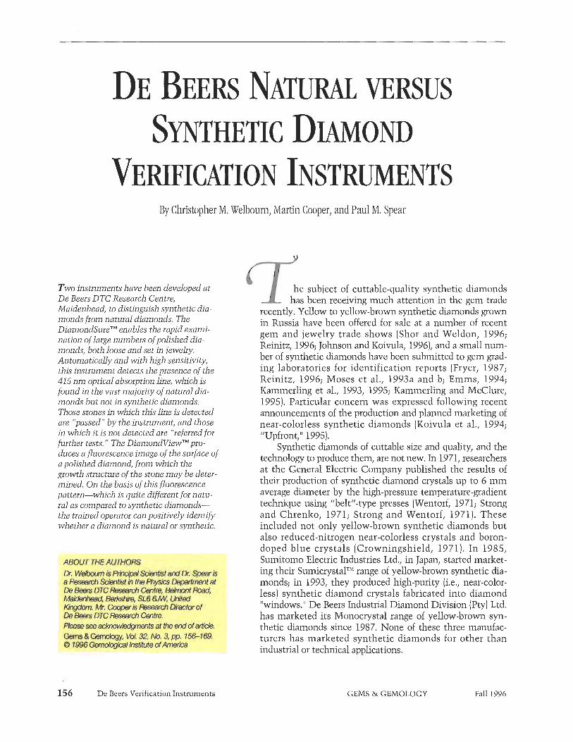
Two instruments have been developed at De Beers DTC Research Centre, Maidenhead, to distinguish synthetic dia- monds from natural diamonds. The DiainondSureTM enables the rapid exami- nation of large numbers of polished dia- monds, both loose and set in jewehy. Automatically and with high sensitivity, this instrument detects the presence of the 415 n m optical absorption line, which is found in the vast majority of natural dia- monds but not in synthetic diamonds. Those stones in which this line is detected are "passed" by the instrument, and those in which i t is not detected are "referred for further tests." The DiamondViewTRf pro- duces a fluorescence image of the surface of a polished diamond, from which the growth structure of the stone may be deter- mined. On the basis of this fluorescence pattern-which is quite different for natu- ral as compared to synthetic diamonds- the trained operator can positively identify whether a diamond is natural or synthetic.
Rise sea acknowledgments at the end of article. Owns à Gamotogy, Vol. 32. No, 3, pp. 156-169. 6 1996 GOTofogtea/ Institute of America
156 De Beers Verification Instruments
he subject of cuttable-quality synthetic diamonds has been receiving much attention in the gem trade
recently. Yellow to yellow-brown synthetic diamonds grown in Russia have been offered for sde at a number of recent gem and jewelry trade shows (Shor and Weldon, 1996; Reinitz, 1996; Johnson and Koivula, 1996)) and a small num- ber of synthetic diamonds have been submitted to gem grad- ing laboratories for identification reports (Fryer, 1987; Reinitz, 1996; Moses et al., 1993a and b; Emms, 1994; Kammerling et al., 1993, 1995; Kammerling and McClure, 1995). Particular concern was expressed following recent announcements of the production and planned marketing of near-colorless synthetic diamonds (Koivula et al., 1994; "Upfront," 1995).
Synthetic diamonds of cuttable size and quality, and the technology to produce them, are not new. In 1971, researchers at the General Electric Company published the results of their production of synthetic diamond crystals up to 6 mm average diameter by the high-pressure temperature-gradient technique using "belt1!-type presses (Wentorf, 1971; Strong and Chrenlzo, 1971; Strong and Wentorf, 1971). These included not only yellow-brown synthetic diamonds but also reduced-nitrogen near-colorless crystals and boron- doped blue crystals (Crowningshield, 1971). In 1985, Sumitomo Electric Industries Ltd., in Japan, started market- ing their SumicrystalTM range of yellow-brown synthetic dia- monds; in 1993, they produced high-purity (i.e., near-color- less) synthetic diamond crystals fabricated into diamond ''windows." De Beers Industrial Diamond Division (Pty) Ltd. has marketed its Monocrystal range of yellow-brown syn- thetic diamonds since 1987. None of these three manufac- turers has marketed synthetic diamonds for other than industrial or technical applications.
GEMS & GEMOLOGY Fall 1996

- Figure 1. Like their predecessors in many other gem materials, cuttable-quality synthetic diamonds pose a potential threat in the diamond marketplace. To protect the integrity of natural diamonds should significant numbers of synthetic diamonds ever enter the trade, De Beers DTC Research Centre has designed and built two types of instruments-the DiamondSure and the Diamondview-that, together, can successfully identify all synthetic diamonds produced by current synthesis equipment. This figure shows, bottom center and to the right, six De Beers experimental synthetic diamonds: two yellow-brown samples weighing 1.04 and 1.56 ct and four near-colorless synthetics ranging from 0.41 to 0.91 ct. A t the top center and to the left are six natural diamonds, ranging from 1.10 ct to 2.59 ct. It is substantially more difficult and costly to grow near-colorless synthetic diamonds than to grow the more usual yellow-brown crystals. De Beers cuttable-quality synthetic diamonds are not available commercially; they have been produced solely for research and education. Natural diamonds courtesy of Louis P. Cvelbar and Vincent Kong, Vincent's fewehy, Los Angeles. Photo 0 GIA and Tino Hammid.
In 1990, researchers from Novosibirsk, Russia, published their work on the temperature-gradient growth of synthetic diamonds in relatively small- scale, two-stage multi-anvil presses laown as "split- sphere" or "BARS" systems (Pal'yanov et al., 1990). Since then, there have been a number of reports of various groups within Russia intending to set up BARS presses for the purpose of synthesizing dia- mond. Usually, only one crystal is grown in a BARS press at any one time, whereas many stones can be grown simultaneously in the larger "belt" presses.
Gemologists from GIA and other gemological laboratories have extensively examined synthetic diamonds from each of the above-mentioned manu-
facturers. Gemological characteristics of these syn- thetics have been published in a series of articles in Gems et) Gemology (Crowningshield, 1971; Koivula and Fryer, 1984; Shigley et al., 1986, 1987, 1992; Rooney et al., 1993; Shigley et al., 1993a and b) and elsewhere (Sunagawa, 1995). The conclusion drawn from these studies is that all of the synthetic dia- monds examined to date can be positively identified by the use of standard gemological techniques. These results have been summarized in "A Chart for the Separation of Natural and Synthetic Dia- monds," published by GIA (Shigley et al., 1995).
The problem facing the gem trade should syn- thetic diamonds become widespread is that, in gen-
De Beers Verification Instruments GEMS & GEMOLOGY Fall 1996

eral, most near-colorless diamonds are examined for grading purposes only, not for identification.
It is to be expected that, in the main, synthetic diamonds would be clearly identified and sold as such by an honest trade working within national laws and regulations. Nevertheless, a small number of synthetic diamonds have already entered the trade without being declared as synthetic. De Beers has long regarded this potential problem as a serious one. For the last 10 years, researchers at De Beers DTC Research Centre have been actively investigat- ing the characteristic features of synthetic diamonds (see, e.g., Burns et al., 1990; Rooney, 1992). This work has been carried out in close collaboration with the De Beers Industrial Diamond Division's Diamond Research Laboratory in Johannesburg, South Africa, which has been developing hgh-pres- surelhigh-temperature diamond synthesis tech- niques for industrial applications for over 40 years. One aspect of this work has been the production of
Figure 2. The DiamondSue is based on the presence or absence of the 415 nm h e in the stone being test- ed. Here it is shown with its fiber-optic probe mounted vertically for testing loose stones.On com- pletion of a test, which takes about 4 seconds, the liquid-crystal display on the front panel will give a message of "PASS" or "REFER FOR FURTHER TESTS" (or sometimes "INSUFFICIENT LIGHT" if the stone is very dark or very strongly colored yellow or yellow-brown). Photo by M. 1. Crowder.
De Beers Verification Instruments
experimental cuttable-quality synthetic diamonds (figure I), with an extensive range of properties, both for research and for loan to the larger gemological laboratories throughout the world to give their staff members an opportunity to develop their own skills and identification techniques. (Note that these syn- thetic diamonds are not for sale by De Beers. The Monocrystal synthetic diamonds available commer- cially from De Beers Industrial Diamond Division (Pty] Ltd. are only sold in prepared forms and are not suitable for cutting as gems.) A second aspect has been the development of instruments that, should the need arise, could be made available to help rapidly identify synthetic diamonds. Such instru- mentation would be important should near-color- less synthetic diamonds enter the market in sigmfi- cant numbers. If this were to happen, grading labora- tories and others in the trade would need to screen substantial numbers of polished diamonds to eliini- nate the possibility of a synthetic diamond being sold as a natural stone and thus damage consumer confidence in gem diamonds.
Although such a circumstance would potential- ly have a profound impact on the conduct of the gem diamond trade, it is important to put the prob- lem into context. The high-pressure apparatus required to grow synthetic diamonds is expensive, as are the maintenance and running costs. In addi- tion, it is substantially more difficult and costly to grow near-colorless synthetic diamonds than it is to grow yellow-brown crystals. To reduce the amount of nitrogen (which gives rise to the yellow-brown color) that is incorporated into the growing crystal, chemicals that preferentially bond to nitrogen are introduced to the synthesis capsule. These chemi- cals, know11 as nitrogen "getters," act as impurities which have an adverse effect on the crystal growth process. To the best of our knowledge, the only near-colorless synthetic diamonds to appear on the gem market thus far were 100 Russian-grown crys- tals displayed at the May 1996 JCK Show in Las Vegas. The largest of these weighed about 0.7 ct, but two-thirds of the crystals weighed 0.25 ct or less. Most of these were not suitable for polishing because of inclusions, internal flaws, and distorted shapes.
Nevertheless, De Beers has considered it pim- dent to invest substantial resources to address this potential problem and thus ensure that the trade is prepared for this eventuality. This article describes two instruments, developed at De Beers DTC Research Centre, that are capable of screening large
GEMS & GEMOLOGY Fall 1996

numbers of diamonds and facilitati~.~ the rapid and unambiguous identification of c-ynthetic diamonds.
Ideally, the trade would like to have a simple instrument that could positively identify a diamond as natural or synthetic with the-same ease as a ther- mal pen distinguishes between diamonds and non- diamond simulants such as cubic zirconia. Unfortunately, our research has led us to conclude that it is not feasible at this time to produce such an ideal instrument, inasmuch as synthetic diamonds are still diamonds physically and chemically, and their distinguishing features are based on somewhat subtle characteristics involving the presence or absence of various forms of impurities and growth structures. The instruments developed at our Research Centre have been designed to be used in a two-stage procedure. The first instrument, called the DiamondSvreT" allows the operator to screen large numbers of stones rapidly. This instrument will successfully detect all synthetic diamonds produced by current equipment (including experimental syn- thetics grown at the Diamond Research Laboratory at extremes of conditions and with non-standard solvent/catalysts). However, a small proportion of natural diamonds will also produce the same response from the instrument. A second stage of examination is therefore required. This could be by standard gemological examination. However, a sec- ond instrument has been developed, called the DiamondViewT~', which enables a positive identifi- cation to be made quickly and easilyl. Certain aspects of the design of these instruments are propri- etary and so cannot be described in this article. However, we have endeavored to give sufficient information on their operation to show clearly how they may be used to identify synthetic diamonds.
THE DIAMOND SURE^^ SCREENING INSTRUMENT Description. The Diamondsure (figure 2) has been designed for the rapid examination of large numbers of polished diamonds, whether loose or set in jewel- ry. It is 268 mm long by 195 mm deep by 107 mm high (10.6 x 7.7 x 4.2 ins.), and it weighs 2.8 kg (6.2 lbs.). Measurements are made by placing the table of a polished diamond on the tip of a fiber-optic probe, the diameter of which is 4 mm. For loose stones', the fiber-optic probe is mounted in a vertical position, and a collar is placed around the end of .the
l ~ h e Diamondsure and Diamondview instruments are covered worldwide by granted or pending patent applications.
De Beers Verification Instruments
Figure 3. The Diamondsire probe can be removed from its mounting to test a diamond in a ring or other setting. Photo by M. 1. Crowder.
probe so that stones can easily be positioned over the probe tip (again, see figure 2). The instrument can be used on diamonds mounted in jewelry pro- vided that the table is sufficiently accessible for the probe tip to lie flat against it (see figure 3). When the probe tip is in contact with the table of the diamond being examined, the operator presses the TEST but- ton on the front panel of the instrument or, altema- tively, presses the button mounted on the side of the probe. The time required for the instrument to complete a measurement is approximately 4 sec- onds. It is designed to work with diamonds in the 0.05-10 ct range. This size range is determined by the diameter of the fiber tip, because the instrument responds to the light that is retro-reflected by the cut diamond and re-enters the probe tip. Should the need arise, fibers with larger or smaller diameters could be manufactured to accommodate larger or smaller stones. The instrument is powered by a uni- versal-input-voltage power supply, and so is suitable for use in any country.
The instrument automatically measures the intensity of retro-reflected light in a small region of the spectrum centered on 415 nm. Using proprietary software, it compares the intensity data, as a func- tion of wavelength, to the 415 nm optical absorption line typically seen in natural diamond. The measure- ment is highly sensitive; values of 0.03 absorbance units at the peak of the 415 nm line, relative to a baseline through the absorption-line shoulders, are
GEMS & GEMOLOGY Fall 1996

easily detected. We detected the 415 nm line in over 95% of all natural diamonds tested by the DiamondSure instrument (see Test Samples and Results section, below), but not in any of the syn- thetic diamonds. If this feature is detected in a stone, the instrument displays the message "PASS." If this feature is not detected, the message "REFER FOR FURTHER TESTS" is displayed. If very dark or very strongly colored yellow or yellow-brown stones are measured, the message "INSUFFICIENT LIGHT" may be displayed. With such stones, the optical absorption in the wavelength range used by the instrument is so strong that practically no light is being returned to the detector. However, in the tests reported in detail in the Test Samples and Results section below, all the yellow-brown syn- thetic diamonds used-including the largest (2.53 ct) sample-tested successfully. If the "INSUFFICIENT LIGHT" message is obtained with a particularly large stone, repositioning the stone on the probe will often produce a valid measurement. If the probe tip does not lie flat against the table, the light detected may be composed mostly of light reflected from the table without entering the diamond. In this case, the instrument would "fail safe" by "referring" the sample.
Although the 415 nrn defect is not present in as- grown synthetic diamonds, it can be formed in nitrogen-containing synthetics by very high-temper- ature heat treatment in a high-pressure press (Brozel et al., 1978). Temperatures in the region of 2350° are required, together with a stabilizing pressure of about 85 lzbars to prevent graphitization. At these extreme conditions, the lifetime of the expensive tungsten carbide press anvils becomes very short, the diamond surfaces are severely etched, and the likelihood that the diamond will fracture is sigmfi- cant. Given the present technology, it would not, therefore, be commercially practical to heat-treat synthetic diamonds to form sufficient 415 nm defects.
A small proportion of natural diamonds, less than 5% from our tests, do not exhibit the 415 nm feature strongly enough to be detected by the Dia- mondsure. These include D-color and possibly some E-color diamonds, as well as some brown diamonds. As for diamonds of "fancy" color, the 415 nm line is absent from natural-color blue (type Db) diamonds, as well as from some fancy yellow and some pink diamonds. When these stones are tested, the DiamondSure displays the message "REFER FOR FURTHER TESTS." It is important to recog-
nize that t h ~ : fact that these stones were not "passed" by the 1i:strument does not necessarily mean that they are synthetic or in any way less desirable than stones that have been passed. The message simply means that additional testing is required for an identification to be made.
Test Samples and Results. During the development of the DiamondSure, approximately 18,000 polished natural diamonds were tested. In the final phase of testing, which we report here, two instruments from an initial batch of 10 were each used to test a total of 1,808 randomly chosen known natural dia- monds. Most of these 1,808 stones weighed between 0.25 and 1.00 ct, although we included some as small as 0.05 ct and some over 10 ct. The largest stone was 15.06 ct, and it tested successfully. Colors were in the D to R range, as well as some browns and some fancy yellows. In these particular tests, all except six stones were round brilliants; in an earlier experiment, though, more than a hundred fancy- shaped stones tested successfully.
The tests were carried out at the London offices of the De Beers Central Selling Organisation. The instruments were used by a number of operators. In general, a combination of daylight and fluorescent lighting was used, but no special care with respect to lighting conditions was necessary. The average figure for "referrals" for these 1,808 diamonds was 4.3%.
In a separate evaluation, we used a third Diarnond- Sure to test 20 D-color stones, of various shapes, ranging from 0.52 to 11.59 ct. Eight of the stones were passed, and 12 were referred. This indicates that, because of its sensitivity, the instrument can detect a very weak 415 nm line even in some D- color stones.
The first two instruments were also tested on a range of De Beers experimental synthetic diamonds. A total of 98 samples were used: 23 in the yellow- brown range, 0.78-2.53 ct; 45 near-colorless, 0.20-1.04 ct; 15 pale-to-vivid yellow, 0.19-0.63 ct; and 15 medium-to-vivid blue, 0.24-0.72 ct. (See fig- ure 1 for examples of the near-colorless and yellow De Beers synthetic diamonds tested.) All of these synthetic diamonds were round brilliants except for one fancy yellow sample, which was an emerald cut. Each was tested 10 times on each instrument. In addition, some yellow and near-colorless Russian BARS-grown synthetic diamonds were tested sever- al times on one of the instruments. In all cases, the synthetic diamonds were "referred for further tests."
160 De Beers Verification Instruments GEMS &. GEMOLOGY Fall 1996

THE DIAMOND VIEW^^ LUMINESCENCE IMAGING INSTRUMENT Background: Growth Structure in Synthetic and Natural Diamonds. In the articles cited above on the gemological characteristics of synthetic diamonds, it was noted that the patterns of ultraviolet-excited fluorescence exhibited by synthetic diamonds are quite distinctive and so can be used to positively identify them. The Diamondview rapidly generates these fluorescence patterns~which are produced by differential impurity concentrations between growth sectors and growth bands-and provides clear images of them. With a little experience, it is relatively easy to recognize patterns that are charac- teristic of natural or synthetic diamonds. With prac- tice, one can obtain and identify the fluorescence images of two or three diamonds per minute.
The reason that fluorescence patterns can be used to identify synthetic diamonds is that the basic growth structure of synthetic diamonds is quite dis- tinct from that of all natural diamonds, and details of these growth structures can be inferred from the fluorescence pattern. Synthetic diamonds grow essentially as cubo-octahedra. The degree of devel- opment of cube (100) or octahedral (111) faces depends on a number of parameters, but most notably on the growth temperature. At relatively low growth temperatures, cube growth predomi- nates; whereas at relatively high growth tempera- tures, the diamond morphology approaches that of an octahedron, although small cube faces are still present (Sunagawa, 1984; see figure 4). For synthetic diamonds grown using pure nickel as the solvent/catalyst, pure cubo-octahedra are produced. However, if other metals are used with or instead of nickel, then minor faces of dodecahedra1 (1 10) and trapezohedral (1 13) orientation also tend to be pre- sent (Kanda ct al., 1989; see figure 5a). In certain cir- cumstances (e.g., when cobalt is a constituent of the solvent/catalyst, and getters have been used to reduce the nitrogen content), additional trapezohe- dral(115) faces may be present (Rooney, 1992; Bums et al., 1996). For large synthetic diamonds grown by the temperature-gradient method, growth starts on a seed crystal of synthetic or natural diamond and develops outward and upward, as illustrated in fig- ure 5b. If the crystal shown in figure 5a were to be sectioned along the planes A and B, the growth pat- terns exposed by these planes would be as shown in figures 5c and dl respectively. (For a comprehensive but easy-to-understand description of the numbers, or Miller indices, used to describe the orientation
I ""
1300 1400 1500 1600 1700 1800 1900
TEMPERATURE PC)
Figure 4. This schematic diagram shows the depen- dence of synthetic-diamond morphology on growth temperature (after Sunagawa, 1984). The Berman- Simon line separates the region in which diamond is the thermodynamically stable phase and graphite is metastable (above the line) from that where graphite is stable and diamond metastable (below the line). Diamond growth can only occw to the right of the solvent/catalyst melting line. The dashed lines approximately represent regions where simi111r mor- phologies are produced, indicating that pressure is also a factor in determining crystal shape.
and position of faces on a crystal, see J. Sinlzanlzas' Mineralogy, 1986, pp. 1 19-127.)
Those regions of a crystal that have a common growth plane are referred to as growth sectors. As the crystal grows, different growth sectors tend to take up impurities i n differing amounts. For instance, nitrogen, the impurity responsible for the yellow to yellow-brown color in synthetic dia- monds, is generally incorporated at highest concen- trations in (1 111 growth sectors, with the concentra- tion in 1100) sectors being about half that of (11 11 (Bums et al., 1990). (However, at low growth tem- peratures, the nitrogen concentration in (100) sec- tors exceeds that of (1 111 [Satoh et al., 19901.1 Nitrogen levels are substantially lower in the (1 13) growth sectors and very much lower in the (110) sectors. The polished slice of synthetic diamond shown in figure 6 was cut parallel to the (1 10) plane, with the seed crystal at the bottom and the (001) face at the top. The variation in nitrogen concentra- tion between growth sectors results in the zonation of the yellow color.
Nickel and cobalt impurities can also be taken up by the growing crystal to form optically active
De Beers Verification Instruments GEMS &. GEMOLOGY Fall 1996
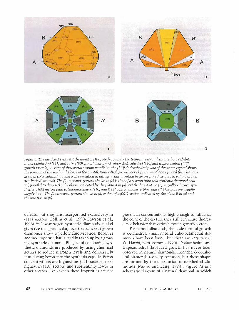
P i p e 5. The idealized synthetic diamond crystal, seed-grown by the temperature-gradient method, exhibits major octahedral {1 11) and cube J100) growth faces, and minor dodecahedra1 { I 101 and trapezohedral {1 131 growth faces (a). A view of the central section parallel to the (1 10) dodecahedra1 plane of this same crystal shows the position of the seed at the base of the crystal, from which growth develops outward and upward (b). The vari- ation in color saturation reflects the variation in nitrogen concentration between growth sectors in yellow-brown synthetic diamonds. The fluorescence pattern shown in (c) is that of a section from this synthetic diamond crys- tal, parallel to the (001) cube plane, indicated by the plane A in (a) and the line A-A' in (b). In yellow-brown syn- thetics, 11001 sectors tend to fluoresce green, { I 10) and 11 13) tend to fluoresce blue. and { I 111 sectors are usually largely inert. The fluorescence pattern shown in (d) is that of a (001) section indicated by the plane B in (a) and the line B-B' in (b).
defects, but they are incorporated exclusively in (1111 sectors (Collins et al., 1990; Lawson et al., 1996). In low-nitrogen synthetic diamonds, nickel gives rise to a green color; heat-treated cobalt-grown diamonds show a yellow fluorescence. Boron is another impurity that is readily taken up by a grow- ing synthetic diamond. Blue, semi-conducting syn- thetic diamonds are produced by using chemical getters to reduce nitrogen levels and deliberately introducing boron into the synthesis capsule. Boron concentrations are highest for (1 11) sectors, next highest in (1101 sectors, and substantially lower in other sectors. Even when these impurities are not
present in concentrations high enough to influence the color of the crystal, they still can cause fluores- cence behavior that varies between growth sectors.
For natural diamonds, the basic form of growth is octahedral. Small natural cubo-octahedral dia- monds have been found, but these are very rare (J. W. Harris, pers. comm., 1990). Dodecahedra1 and trapezohedral flat-faced growth has never been observed in natural diamonds. Rounded dodecahe- dral diamonds are very common, but these shapes are formed by the dissolution of octahedral dia- monds (Moore and Lang, 1974). Figure 7a is a schematic diagram of a natural diamond in which
162 De Beers Verification Instruments GEMS & GEMOLOGY Fall 1996

Figure 6. This optical micrograpn 01 a slice cut paral- lel to the (1 10) dodecahedral plane from a De Beas yellow-brown synthetic diamond shows the greater concentration of nitrogen (and thus greater sat~ration of yellow) in the 11 11) growth sectors than in the 11 001, 11 131, or { I 101 growth sectors (again, refer to fig- ure 5b for a diagram of the different growth stnzctues in such a crystal a1 this orientation). The slice is 5.01 mm across x 3.20 m m high x 0.71 m m thick.
the octahedral faces have undergone partial dissolu- tion so that rounded dodecahedral faces are hegin- ning to form. A schematic diagram of a section through a central cube plane of t h s idealized crystal is shown in figure 7b.
Dodecahedra1 faces that appear flat may be
found on "coated1! diamondsl but here the growth is fibrous and quite distinct from flat-faced { l lo] growth (Machada et al.! 1985).
A fonn of nonoctahedral growth that is relative- ly common in natural diamonds is so-called cuboid growth. The mean orientation of cuboid growth is approximately along cube planes! but the growth is hummocky and distinct from flat-faced cube growth. On the rare occasions that cuboid growth is well developed compared to octahedral growth! dia- inonds with quite spectacular shapes are producedl as is the case with the "c~~bes" found in the Jwaneng mine (Welboum et al.! 1989). It is not uncommon for otherwise octahedrally grown damonds to have experienced a limited amount of cuboid growth! par- ticularly on re-entrant octahedral faces. This is shown schematically in figure 7b.
For most natural diamonds! the conditions in which they grew fluctuated over time! so different types and levels of impurities were incorporated at different stages of growth, This resulted in differ- ences in fluorescence behavior between growth bands within the crystal.
Uncut synthetic diamonds can be readily identi- fied by visual inspection because of their crystal morphology and the remnants of the seed crystal present. However, these external features are lost when the stone is polished.
For many years, cathodolu~escence topogra- phy has been used to image growth-dependent pat-
Figme 7. In this schematic diagram of (a) the morphology of (1 typical natural diamond, the octahedral faces, decorated wit11 trigon etch pits, have undergone partial dissolution so that rounded dodecahedral faces are beginning to form. The schematic diagram of the fluoresc~nce pattern {ram a section through a central cube plane of h s idealized crystal (b) shows concenLric rectangular baz~ds of octahedral grow~h and regions where re- enuant features have been overgrown by cuboid growth.
De Beers Verification Instruments GEMS & GEMOLOGY Fall 1996

Figre 8. The Diamond- View consists of a fluo- rescence imaging unit (left) in which he TV camera is located between two lamp housings (upper left), with special stone hold- ers for loose (foreground and figre 90) and ring- set (foreground and fig- ure 9b) diamonds, and a specially configured computer. Photo by
terns in mineralsl including diamond (Woods and Lang! 1975; Hanley et al.! 1977; Marshall! 1988; Ponahlol 1992). In cathodoluminescence (CL)! an electron beaml rather than ultraviolet radiation! is used to excite luminescence. Commercial CL instruments use a cold cathode dischuge tube oper- ating in a relatively low vacuuin to produce the electron beam. Although CL is invaluable in the study of minerals! the fact that it requires a vacuum can be a disadvantage when large numbers of stones must be surveyed rapidly! as it may take several minutes to pump down to the required pressure. Also! the surfaces of samples may become contami- nated by deposits of proclucts from the pump oil. It was to avoid these practical problems associated with CL that our Research Centre developed an ultraviolet-excited fluorescence imaging technique.
Description of the Diamondview. The Diamond- View consists of a fluorescence imaging unit (60 cm h g h by 25 cin wide by 25 cm deep (24 in. x 10 in. x 10 in.)l which weighs approximately 20 1% (44 lbs.j1 and a specially configured computer (figure 8). Loose stones are mounted between the jaws of a stone holder that allows the stone being examined (from 0.05 to approximately 10 ct) to be rotated about a horizontal axis while it is being viewed (see figure 9a). Rmg-mounted stones can also be examined! pro- vided that the total height of the ring is not too great (see figure 9b). Other simple jewelry mounts can also be accommodated.
The instrument ill~lminates the s~~rface of a dia-
De Beers Verification Instruments
mond with intense ultraviolet light! specially fil- tered such that almost all of the light reaching the sample is of wavelengths shorter than 230 nm. The energy of this ultraviolet light is equal to or greater than the intrinsic energy hand-gap of diamonds. This has two important consequences. First! radia- tion of this energy will excite fluorescence in practi- cally all types of diamond irrespective of whether they fluoresce to the standard long- and short-wave W radiation (365 and 254 nm, respectively) routine- ly used by gemologists. Second! at wavelengths shorter than 230 nml all types of diamond absorb light very strongly, T h s means that fl~~orescence is generated very close to the surface of the &amondl so that a clear two-dimensional pattern can be observed. The fluorescence emitted is viewed by a solid-state CCD (charge-coupled device) video cam- era that has been fitted with a variable-magnifica- tion objective lens. The camera has a built-in video pict~lre storel and images can be integrated on the CCD chip from 40 milliseconds up to 10 seconds! dependmg on the intensity of the fluoresecence.
To examine a stone! the operator inserts the loaded stone holder into the port at the front of the unit. An interloclcing safety mechanism eliminates the possibility of any ultraviolet light escaping from the instrument when the stone holder is out of the port. The stone is first illuininated with visible light and the camera is focused onl say! the table of the diamond. The stone is then illuminated with ultra- violet light and the fluorescence image is recorded. The instrument is controlled by an BM PC-compati-
GEMS & GEMOLOGY Fall 1996

Figure 9. The loose-stone holder is inserted into the measzlrement port of the Diamondview (left), The gear mecha- nism allows the stone to be rotated abozzt 0 horizontal axis while located within the instrument, Jor alignment and observation of surface fluorescence patterns characteristic of its internal g~owth structures. The ring holder (right) can accommodate a ring-set stone that has a total height no greater than 30 m m (1.2 in). Rings mounted in this holder can be rotated about the axis of the holder and moved forward and backward along ihis axis. Photo by M. J. Crowder.
ble computer running micros oft@ WindowsTh' 3.1-compatible proprietary software. The computer has a 12â‚ MJ3z Pentium processorl 32 Mb of RATvI (random access m e m ~ r y ) ~ and PC1 (peripheral com- ponent interconnect) video inp~it and graphics dis- play cards. The fl~~orescence image is displayed on a high-resolutionf 1024 x 768 pixel! computer moni- tor. If additional views of the stone are required, the stone holder can be rotated! without removing it from the chamber! to bring other parts of the stone's
Figure 10. 7'his fluorescence image of a 0.3 ct near- colorless nat~ral diamond shows concentric bands of oc~ahedral growth with a re-entrant featzre below the center of the image and several regions of hum- mocky cuboid growth. The blue color is typical of most natural diamonds and results from so-called band A emission together with some flzrorescence from the 415 nm system.
surface into view. Fl~~orescence images that are required for future reference can be stored on the PC's hard drive. The number of images that can be stored is limited only by the size of the hard drive. In this modell the 800Mb drive could hold over 500 images. Images can be archived using! for instance! a tape drive or writable compact dislc. The display screen produced by the DiamondView software can be seen in figure 8. The mouse-operated buttons that control the instnlinent are located beneath the main window! in which the current image is dis- played. This image may be compared with up to 16 previously recorded images. These can be recalled on four pages! each of which has four "thumb-nailtf windows! displayed on the right of the main win- dow. Tutorial files consisting of 16 'lthumb-nailll images! complete with text notesf are provided in the software to help the operator identify fluores- cence patterns. The user can also produce "cus- tomized!' t~itorial files.
Sample Images. The DiamondView was tested with the same synthetic diamonds described above for the Diamoi~dSure tests, together with about 150 randomly chosen nat~iral diamonds. Following are some examples of the images obtained. Figure 10 shows the fluorescence image of a near-colorless na t~~ra l 0.3 ct diamond mounted in an eight-claw ring setting. The fluorescence in this sample ranges from bright blue to darli blue; it is typical for natural diamonds and results from so-called blue band A emission together with some fluorescence from the 415 nm system (see! e.g.! Clark et al., 1992). The stone was polished such that the table is close to a cube plane, and the striae visible in the image result
De Beers Verification Instr~i~nents GEMS & GEMOLOGY Fall 1996

from bands of octahedral growth intersecting the table. Re-entrant features are evident in the lower part of the image) and cuboid growth horizons can be seen in various placesl partic~~larly toward the left in the image. The concentric rectangular bands) the re-entrant feature below the center of the image) and the hummoclzy cuboid growth bands are all similar to those shown in idealized form in figure a.
Figure 12. In this yellow-brown plastically deformed natural diamond, approximately 0.1 ct, the fl~lores- cence imoge shows green H3 (503 nm) emission /ram two sets of parollel slip bonds. This type of plastic deformation, covering the entire stone, is not unwmmon in natural diamonds, but it has not been found in synthe~ic diamonds.
166 De Beers Verification Instruments
Figure 11. The f l~~ores- cence imoge of the ~ob le (left) of this 1.5 ct na~ural diamoi~d shows concen- tric bonds of octahedral growth and a 11 L I ~ ber of re-entrant features. The pavilion of this sLone (right) shows some nar- row bright blue oc~ohe- &a1 bands, with some re-entrant features, in an otherwise wealzly fluo- rescing region.
The fluorescence iinage of a 1.5 ct near-colorless natural diamond is shown in figure 11 (left). The ban* is less pronounced in this stone than in the one shown in figure 10) but it is still apparent. However) the image of part of the pavihon of this stone shows greater contrast) as is evident in figure 11 (right).
The fluorescence image of an approximately 0.1 ct yellow-brown natural diamond is shown in fig- ure 12. This diamond is plastically deformedl and the green lines are produced by slip bands (planes along which part of the crystal has undergone a shearing displacement) decorated by nitrogen-relat- ed H3 (503 nm) defects, Two sets of parallel slip bands may be seen. This type of plastic deforma- tion) which covers the entire stone) is not uncom- mon in natural diamonds but has not been found in synthetic hamonds,
The Diamondview image of a 2.19 ct yellow- brown De Beers experimental synthetic diamond is shown in figure 13. From the syminetry of the pat- tern) it is clear that the table has been cut close to a cube plane. This image may be compared with the schematic diagram shown in figure 5c. The central (001) sector is s~~rrounded by four other cube sec- tors) which fluoresce yellowish green) and by four inert octahedral sectors. The yellowish green color is due to the H3 (503 nin) system together with some green band A emission (again) see Clarlz et al.) 1992). Narrow) blue-emitting dodecahedra1 sectors lie between pairs of cube and pairs of octahedral sectors.
The fluorescence iinage of a 0.33 ct near-color- less De Beers experimental synthetic diamond is shown in figure 14 (left). Although the fluorescence is blue) it is a less saturated) more grayish blue than is typical of natural diamonds (again) see Shigley et al.) 1995). A brief examination of this image reveals
GEMS &. GEMOLOGY

Figure 13. The fluorescence image of the table and some of the surrounding crown facets of this 2-19 ct yellow-brown De Beers experimental synthetic dia- mond shows yellowish green emission from the cen- tral(001) sector f lndjo~u other cube sectors, The color is due to the nitrogen-related H3 (503 nm) system together with some green band A emission, The inert regions between the yellowish green cube sectors are octahedral sectors. Narrow, blue-emitting dodecahe- &a1 sectors lie between pairs of cube sectors and pairs of octahedral sectors. Trapezohedrd 11 13) sectors had not developed significantly in this sample,
a central (001) sector s~mounded by f o ~ r somewhat brighter octahedral sectors. Pairs of octahedral sec- tors are separated by narrow, less intensely emitting
dodecahedral sectors. The view of the pavilion of this stone (figure 14! center) shows the growth-sec- tor pattern even more clearly. A wealdy emitting (001) sector may be seen in the region of the culet. This is surro~~nded by pale blue { I l l ) sectors lying between nmow, less strongly emitting {l lo] sectors.
The DiamondView has also been used to exain- ine a complete range of synthetic diamonds! including both yellow and near-colorless Russian BARS stones. In all cases, the stones could be posi- tively identified as synthetic from their fluores- cence patterns.
Another feature of near-colorless and b l ~ ~ e syn- thetic diamoi~ds is that they tend to exhibit long- lived phosphorescence after excitation by ultraviolet light. Many natural diamonds do phosphoresce, but phosphorescence is relatively uncommon in near- colorless stones and is generally much weaker and for a shorter period than in near-colorless and blue synthetic diamonds. The DiamondView instrument has been designed to exploit this phenomenon in order to assist further in the identification process. Phosphorescence images can be captured at times from 0.1 to 10 seconds after the ultraviolet excita- tion has been switched off. An example of a phos- phorescence image from the 0.33 ct near-colorless synthetic diamond is shown in figure 14 (right). The exposure time was 0.4 second, commencing after a delay of 0.1 second. Phosphorescence is strongest from octahedral growth sectors.
Figure 14, The fluorescence image of the crown (left) oj this 0.33 ct near-colorless De Beers experimental syn- thetic diamond shows a near-central(OO1) sector surrounded by four somewhat brighter octahedral sectors, which are separated by narrow dodecahedra1 sectors. The blue wlor is less saturated than is typical of natural diamonds. The view of the pavilion (center) shows a weakly emitting (001) sector in the region of the C L ~ ~ L sur- rounded by pale blue octahedral sectors lying between narrow, less strongly emitting dodecahedra1 sectors. A phosphorescence image (right), recorded with an exposure time of 0.4 second and a delay of 0.1 second after the ultraviolet excitation had been switched off, shows strongest vhosvhorescence from octahedral sectors. Strong, long-lived phosphorescence is a characteristic feature o less and blue synthetic diamonds.
De Beers Verification I n s t r ~ ~ n ~ e n t s GEMS & GEMOLOGY Fall 1996

We have loaned the GIA Gem Trade Laboratory DiamondView and DiamondSure instruments, which they are evaluating for use as part of GIA GTL's standard diamond testing procedures. In this evaluation, the Diamondsure is the first test for all diamonds that the laboratory takes in (T. Moses, pers. comm., 1996). Using the DiamondView, GIA Research in Carlsbad, California, recorded fluores- cence patterns on eight Russian and three Sumitorno Electric synthetic diamonds (all yellow). From these patterns, all of these diamonds were quickly and easily recognized as synthetic (J. E. Shigley, pers. comm., 1996).
CONCLUSION The Diamondsure is a relatively inexpensive instru- ment capable of screening 10 to 15 stones per minute and automatically producing a "PASS" or "REFER FOR FURTHER TESTS" result. It is based on the presence or absence of the 415 nm line, which was found in more than 95% of natural dia- monds tested but has not been found in any syn- thetic diamonds. Because a small proportion of nat- ural diamonds would be referred by this instrument, additional testing may be required. The DiamondView is a more complex and significantly more expensive instrument. It enables the operator to determine whether a diamond is natural or syn- thetic on the basis of a far-ultraviolet-excited fluo- rescence image. Synthetic diamonds are identified by their distinctive growth-sector structure, whereas natural diamonds show either purely octahedral growth or a combination of octahedral and hum- mocky "cuboid" growth. Because only two or three stones can be examined per minute, and an operator must interpret the fluorescence image, it would not be practical to use the DiamondView alone for screening large numbers of stones. It would there-
fore be appropriate for both instruments to be used together or for operators of a DiamondSure to have ready access to a laboratory with a DiamondView.
At present, DiamondSure and DiamondView instruments are being loaned to a number of major gem testing laboratories throughout the world. Both instruments have been designed so that they can be manufactured in volume should near-colorless cut- table synthetic diamonds enter the gem market in significant numbers. Although it has yet to be shown that this will be the case, these instruments could be made commercially available quickly, should a real need arise. The price of the instru- ments will depend very much on the numbers to be produced, but it is estimated that a DiamondSure instrument might cost in the region of a few thou- sand dollars, whereas the more complex Diamond- View might be 10 times as much.
The development of these instruments ensures that synthetic diamonds of cuttable quality can be easily identified. With such tools available to mem- bers of the gem trade, the existence of such synthet- ics should not be a cause of major concern.
- -~
Aclznowledgments: The authors wish to thank all the members of the staff at De Beers DTC lxesearch Centre, Maidenhead, who have been involved with the develop- ment of the instruments described in this article. Particular recognition is due to P. S. Rose and G. M. Brown, for the development of the Dia~nondSure"~ instrument, and to T. M. Payman and R. M. Caddens, for the development of the DiamondViewrhr instrument. S. f. Quinn was responsible for most of the instrument testing. The authors are also grateful to the synthesis team under Dr. R. C. Burns at the Diamond Research Laboratory, fohannesburg, for the supply of the De Beers experimental synthetic diamonds used to test these instruments.
REFERENCES Brozel M.R., Evans T., Stephenson R.F. (1978) Partial dissociation
of nitrogen aggregates in diamond by high temperature-high pressure treatments. Proceedings of the Royal Society of London, A, Vol. 361, pp. 109-127.
Bums R.C., Cvetkovic V., Dodge C.N., Evans, D.J.F., Rooney M.- L.T., Spear P.M., Welbourn C.M. (1990) Growth-sector depen- dence of optical features in large synthetic diamonds. journal of Crystal Growth, Vol. 104, pp. 257-279.
Burns R.C., Kessler S., Sibanda M., Welbourn C.M., Welch D.L. (1996) Large synthetic diamonds. In Advanced Materials '96: Proceedings of the 3rd NIRIM International Symposium on
Advanced Materials, National Institute for Research in Inorgiinic Materials, Tsukuba, Japan, pp. 105-1 1 1.
Clark C.D., Collins A.T., Woods G.S. (1992) Absorption and luminescence spectroscopy. In J. E. Field Ed. The Properties of Natural and Synthetic Diamond, Academic Press, London, pp. 35-79.
Collins A.T., Kanda H., Burns R.C. (1990) The segregation of nickel-related optical centres in the octahedral sectors of syn- thetic diamond. Philosophical Magazine B, Vol. 61, No. 5, pp. 797-810.
Crowningshield R, (1971) General Electric's cuttable synthetic
168 De Beers Verification Instruments GEMS & GEMOLOGY Fall 1996
diamonds. Gems a) Gemology, Vol. 13, No. 10, pp. 302-314. Ernms E.C. (19941 Large gem-quality synthetic diamond identified
by laboratory. Gem andJewellery News, Vol. 4, No. 1, p. 4. Fryer C.W. (1987) Gem trade lab notes: Synthetic diamond. Gems
a) Gemology, Vol. 23, No. 1, p. 44. Hadey P.L., Kiflawi I., Lang A.R. (1977) On topographically iden-
tifiable sources of cathodoluminescc5nce in natural diamonds. Philosophical Transactions of the Royal Society of London, A, Vol. 284, No. 1324, pp. 329368.
Johnson M.L., Koivula J.I., Eds. (1996) Gem news: Synthetic dia- monds are in the marketplace. Gems a) Gemolosy, Vol. 32, -.
No. 1, p. 52. Kammerline R.C.. Moses T., Fritsch E. 119931 Gem trade lab
notes: Faceted ye l lowsynthe t ic diamond. Gems a) Gemology, Vol. 29, No. 4, p. 280.
Kammerling R.C., McClure S.F. (19951 Gem trade lab notes: Synthetic diamond, treated-color red. Gems a) Gemology, Vol. 31, No. 1, pp. 53-54.
Kammerling R.C., Reinitz I., Fritsch E. (19951 Gem trade lab notes: Synthetic diamond suite. Gems a) Gemology, Vol. 31, No. 2, pp. 122-123.
Kanda H., Ohsawa T., Fukunaga 0 . (19891 Effect of solvent met- als upon the morphology of synthetic diamonds. Journal of Crystal Growth, Vol. 94, pp. 115-124.
Koivula J.I., Fryer C.W. (19841 Identifying gem-quality synthetic diamonds: An update. Gems a) Gemology, Vol. 20, No. 3, pp. 146-158.
Koivula J.I., Kamrnerling R.C., Fritsch E., Eds. (1994) Gem news: Near-colorless Russian synthetic diamond examined. Gems aà Gemology Vol. 30, No. 2, pp. 123-124.
Lawson S.C., Kanda H., Watanabe K., Kiflawi I., Sato Y. (1996) Spectroscopic study of cobalt-related optical centers in syn- thetic diamond. J o u m l of Applied Physics, Vol. 79, No. 8, pp. 1-10.
Machada W.G., Moore M., Woods G.S. (1985) On the dodecahe- dial growth of coated diamonds. Journal of Crystal Growth, Vol. 71, pp. 718-727.
Marshall D.J. (1988) Cathodoluminescence of Geological Materials, Unwin Hyman Ltd., London.
Moore M., Lang A.R. (1974) On the origin of the rounded dodeca- hedral habit of natural diamond. lournal of Crystal Growth, . . Vol. 26, pp. 133-139.
Moses T.. Kammerline R.C.. Fritsch E. f1993al Gem trade lab notes:Synthetic yellow di'amond crystal. ~ e h s e9 Gemology, Vol. 29, No. 3, p. 200.
Moses T., Reinitz I., Fritsch E., Shigley J.E. (1993b) Two treated- color synthetic red diamonds seen in the trade. Gems a) Gemology Vol. 29, No. 3, pp. 182-190.
Pal'yanov Yu.N., Malinovsky I.Yu., Borzdov Yu.M., Khokhryakov A.F., Chepurov A.I., Godovikov A.A., Sobolev N.V. (19901 Use of the "split sphere" apparatus for growing large diamond crystals without the use of a hydraulic press. Doklady Alzademii Naulz SSSR, Earth Science Section, Vol. 315, No. 5, pp. 1221-1224.
Ponahlo J. (19921 Cathodoluminescence [CL) and CL spectra of De Beers' experimental synthetic diamonds. Journal of Gemmology, Vol. 23, No. 1, pp. 3-17.
Reinitz I. (1996) Gem trade lab notes: A notable yellow synthetic diamond from Russia. Gems a) Gemology, Vol. 32, No. 1, pp 44-45.
Rooney M.-L.T. (1992) 11 15) Growth in boron-doped synthetic diamonds. Journal of Crystal Growth, Vol. 116, pp. 15-21.
Rooney M.-L.T., Welboum C.M., Shigley J.E., Fritsch E., Reinitz I. (1993) De Beers near colorless-to-blue experimental gem-qual- ity synthetic diamonds. Gems a) Gemology, Vol. 29, No. 1, pp. 3845.
Satoh S., Sumiya H., Tsuji K., Yazu S. (1990) Differences in nitro- gen concentration and aggregation among (111) and (100) growth sectors of large synthetic diamonds. In S. Saito, 0. Fukunaga, and M. Yoshikawa, Eds., Science and Technology of New Diamond, KTK Scientific Publishers/Terra Scientific Publishing Co., Tokyo, pp. 351355.
Shigley J.E., Fritsch E., Stockton C.M., Koivula J.I., Fryer C.W., Kane R.E. (1986) The gemological properties of Sumitomo gem-quality yellow synthetic diamonds. Gems a) Gemology, Vol. 22, No. 4, pp. 192-208.
Shigley J.E., Fritsch E., Stockton C.M., Koivula J.I., Fryer C.W., Kane R.E., Hargett D.K., Welch C.W. (1987) The gemological properties of the De Beers gem-quality synthetic diamonds. Gems a) Gemology, Vol. 23, No. 4, pp. 187-206.
Shigley J.E., Fritsch E., Reinitz I., Moon M. (19921 An update on Sumitomo gem-quality synthetic diamonds. Gems d Gemology, Vol. 28, No. 2, pp. 116-122.
Shigley J.E., Fritsch E., Reinitz I. (1993a) Two near-colorless General Electric type Da synthetic diamond crystals. Gems &> Gemology, Vol. 29, No. 3, pp. 19 1-197.
Shigley J.E., Fritsch E. Koivula J.I., Sobolev N.V., Malinovsky I.Yu., Pal'yanov Yu.N. (1993b) Gemological properties of Russian gem-quality synthetic yellow diamonds. Gems a) Gemology, Vol. 29, No. 4, pp. 228-248.
Shigley J.E., Fritsch E., Reinitz I., Moses T.M. (1995) A chart for the separation of natural and synthetic diamonds. Gems a) Gemology, Vol. 31, No. 4, pp. 256-264.
Shor R., Weldon R., Eds. (1996) Gem notes: Superings to market Russian synthetics. Jewelers' Circular-Keystone, May, pp. 62-63.
Sinkankas J. (19861 Mineralogy. Van Nostrand Reinhold Co., New York.
Strong H.M., Chrenko R.M. (1971) Further studies on diamond growth rate and physical properties of laboratory-made dia- mond. Journal of Physical Chemistry, Vol. 75, No. 12, pp. 1838-1843.
Strong H.M., Wentorf R.H. Jr. (1971 1 The growth of large diamond crystals. Die Nahuwissenschaften, Vol. 59, No. 1, pp. 1-7.
Sunagawa I. (1984) Morphology of natural and synthetic diamond crystals. In I. Sunagawa, Ed., Materials Science of the Earth's Interior, Terra Scientific Publishing Co., Tokyo, pp. 303-330.
Sunagawa I. (19951 The distinction of natural from synthetic dia- monds. Journal of Gemmology, Vol. 24, No. 7, pp. 485-499.
Upfront: Chatham bombarded with calls after broadcast (19951. Jewelers' Circular-Keystone, May, p. 26.
Welboum C.M., Rooney M.-L.T., Evans D.J.F. (1989) A study of diamonds of cube and cube-related shape from the Jwaneng mine. J o d of Crystal Growth, Vol. 94, pp. 229-252.
Wentorf R.H. Jr. (1971) Some studies of diamond growth rates. Jo~irnal of Physical Chemistry, Vol. 75, No. 12, pp. 1833-1837.
Woods G.S., Lang A.R. (1975) Cathodoluminescence, optical absorption and X-ray topographic studies of synthetic dia- monds. Jownal of Crystal Growth, Vol. 28, pp. 215-226.
De Beers Verification Instruments GEMS & GEMOLOGY Fall 1996

Identification of the Negative d Plane in Natural Ruby
By Christopher P, Smith
Growth-struct~~re analysis has become increasingly important as a gemological tool for locality classification and distinguishing between natural and synthetic geinstones. This article presents the methods and instru- ments needed to analyze the internal growth structures of corundum. As an application of this testing procedure, the negative r l~om bohe- dial d (01 12) plane is documented as p a n of the crystal habit in a small number of natural rubies-bolh as a subordinate form and, for the first time in natural rubies, as a dominant crystal form. Until recently, this crystal face was primarily associated with flux-grown syn- thetic rubies and sapphires.
0 ver the past several years, the analysis of crystal habits and internal growth features observed in gem-
stones has gone beyond the realm of purely academic crystallography to applications in gem identification. The wealth of information learned through the determination of external habits and internal growth structures, which reflect the conditions in which the gem grew, can aid in (1) the sep- aration of natural and synthetic gem materials, as well as (2) the identification and characterization of gemstones from different deposits around the world (figure 1).
For example, the type of twinning is an important factor in separating natural from synthetic amethyst (see, e.g., Crowningshield et al., 1986; Koiv~ila and Fritsch, 1989; Kiefert and Schmetzer, 1991~). In diamond, internal growth structures (commonly referred to as graining) can affect the clarity of the stone (see, e.g., Kaiie, 1980) and be responsible for certain color manifestations (see, e.g., Kane, 1980; Hofer, 1985; Kane, 1987). These and other growth structures also aid in the separation of natural and synthetic diamonds (see, e.g., Shigley et al., 1992, 1993; Sunagawa, 1992; Rooney et al., 1993; and the Welboum et al., 1996, article elsewhere in this issue on the new De Beers DiamondView instrument). Beryl classification from various sources, in addition to the separation of natural from synthetic emeralds, has also bene- fited from the study of internal and external growth features see, e.g., Lind et al., 1986; Kiefert and Schmetzer, 1991b; Schmetzer et al., 1991).
In corundum in particular, growth-structure analysis has become a standard procedure in many laboratories for both source determination and natural versus synthetic distinc- tions (see, e.g., Schmetzer, 19868 and b; Schn~etzer, 1987; Kiefert, 1987; Kiefert and Schmetzer, 1987, 1988, 199 lcj Hanni and Schmetzer, 1991; Peretti and Smith, 1993; Hanni
Internal Growth Structures GEMS & GEMOLOGY Fall 1996

Figure 1. A wealth of infor- malion can be learned tlvough the analysis of
internal growth structures, incl11ding the distinction of natwal from synthetic gem materials and the probable locality of origin of i iat~ral
stones. With a relatively sin~ple equipment set-up, some study, and practice,
the professional gemologist can make determinations
that otherwise might require sophistica ted
instrumentation available to only the most advanced
laboratories. Some oflhe 171ost intense investigation
has been done on rubies, so that fine natural rubies
such as those shown here (63 ct total weight in the bracelet, 40 ct in the ear-
rings) can be- properly iden- tified. Bracelet and earrings courtesy of Harry Winston
Inc.; photo 0 Harold e.0 Erica Van Pelt.
et al., 1994; Schmetzer et al., 1994; Sinith and Surdez, 1994; Peretti et al., 1995; Smith et al., 1995).
To make tills new tool more accessible to geinol- ogists in all areas of the industry, this article describes the basic techniques and instrun~entation that can be used to perform growth-structure analysis of gems. It also provides an example of how tiis procedure was recently applied to identify in natural rubies a rare crystallographic feature that had previously been con- sidered an indicator of flux-grown synthetic rubies.
GROWTH-STRUCTURE ANALYSIS ~aclzground. Understanding of the methods and applications that will be presented here requires, first, an explanation of some fundan~entals of the analysis of internal growth structures. The external form of a crystal consists of a combination of indi-
vidual crystal faces. The relative size and number of these faces dictate the overall external shape, or habit, of the crystal (figure 2). Which crystal faces form and their relative prominence are heavily influenced by the conditions of formation (e.g., pres- sure/temperature relationships, chemical fluctua- tions of the fluids from which the crystals precipi- tated, etc.). Consequently, analysis of these habits can provide important information concerning the way a particular gemstone grew. However since the external habit of a stone is removed during the fash- ioning process, internal growth features are the only means to identify the original habit and crystal- growth characteristics in a faceted or polished gem.
The internal growth structures represent the succession of crystal "habits" that formed while the crystal was growing (figure 3). (That is, internal
Internal Growth Structures GEMS & GEMOLOGY Fall 1996

Figure 2. The external form, or habit, of a crystal is made up of a collection of various crystal faces. The number and relative prominence of these crystal faces can have a significant influence on the overall shape of the crystal. Shown here are bipyramidal (left) and tabular (right) blue sapphire crystals from Sri Lanka. The line diagrams illustrate which crystal faces comprise the habits of these two crystals: the basal pinacoid c (0001), the positive rhombohedron i: (Ion), the hexagonal dipyramid w (1121). and the second-order prism a (1120). Photo by Shane F. McClure.
growth planes were at one point external crystal faces. For consistency, the word plane will be used to refer to internal crystal forms, and the word faces will be reserved for describing external crystal forms.) Minerals form over a long period of time-sometimes continuously and sometimes discontinuously-until the conditions of die formation environment can no longer sustain that mineral's growth. This change in conditions can happen for a variety of reasons. For example, the crystal may be removed from the growth environment by geologic forces, or the growth environment no longer has the chemical/physical requirements (composition of fluids, temperature, pressure) to support the continued formation of that mineral, or there may be no more space for expansion because of competition from other minerals.
The internal structures that indicate the growth of a crystal can be compared to the "rings" of a tree. Just as each "ring" represents one year's growth of tree bark, the internal growth structures illustrate various stages in the history of a crystal's formation. Internal growth features can be observed in transpar- ent gem materials in a variety of ways: as color zon- ing (which can fluctuate between the different stages of growth); by inclusions that form and con- centrate along crystal faces, or coat the crystal's entire surface at one growth stage and then are enclosed by later phases (the latter is how "phan- toms" are formed); or by the presence of "lines" that represent the interface or contact plane between consecutive stages of growth. These lines generally are visible with a microscope only when the interior of the gemstone is viewed in a direction parallel, or
Internal Growth Structures
nearly parallel, to the traces of a specific plane, par- ticularly if the stone is immersed in a liquid of simi- lar refractive index (to reduce the reflection of light).
The appearance of these lines can be visualized by imagining a common type of window in which two sheets of glass have been vacuum sealed togeth- er. When you look perpendicular to the glass plane (i.e., as you would normally look through a win- dow), the objects on the other side are not obstruct- ed. However, if you examine the glass parallel to its main surface (i.e., along the edge), a "line" is visible where the two sheets of glass meet.
In 1985, Dr. Karl Schmetzer published his first paper dealing with the methods for determining internal growth structures in some uniaxial gem- stones, with specific focus on corundum, beryl, and quartz (see also Schmetzer, 1986a). For a more in- depth discussion on methods and applications of determining growth structures in some uniaxial gemstones, the reader is referred to these papers and others by Schmetzer (1985, 1986a and b), Kiefert and Schmetzer (1991a-c), and Peretti et al. (1995). Following is a brief, step-by-step description of how to use this technique; it has been written specifical- ly for those gemologists, like the author, who do not have a formal background in crystallography.
The Technique. The manner in which specific crys- tal planes can be identified relates to: (1) the posi- tion, or the angle, that the planes form relative to the optic-axis direction of the uniaxial gemstone; and (2) the angle created by the joining of two planes. In the technique used by the author to iden-
GEMS & GEMOLOGY Fall 1996

tify crystal planes, the equipnient includes: a stone holder, modified by the author, which allows for rotation about both the vertical and horizontal axes (Box A); a horizontal niicroscope; an immersion cell containing methylene iodide;.and a light source located behind tlie gemstone so light is transmitted through it (figure 4). Note that growth structures, color zoning, and the like, can also be seen, but not measured, with a standard binocular microscope using darkfield and various other illumination tech- niques. However, immersing the gemstone in a liq- uid will reduce die distortion of light and other detri- mental effects, thereby significantly improving the visibility (and measurability] of the growth struc- tures. The recommended procedure is as follows:
First examine each specimen with magnifica- tion in the immersion liquid to locate any color banding or other structural features that might be present. Then position the stone in the stone holder so that the direction of the growth planes selected for identification is oriented vertically, that is, per- pendicular to the platform base that holds the immersion cell, thus allowing for the most accurate measurenient of the angle between the optic-axis direction and the growth plane to be identified. The author has added this first step to the methods described by Schmetzer (1985, 1986a and b) and Kiefert and Schmetzer (1991a-c), in order to guaran- tee the most accurate measurement for those just beginning to use this testing method. When the growth planes are not in a vertical direction, but rather are at an angle, the angles measured may be off by a couple of degrees, thereby decreasing the accuracy of the technique.
Next, center the optic axis (c-axis) of the gem- stone both horizontally and vertically, parallel to the observer's field of view. This is acconiplished by using a pair of crossed polarizing filters and the dual-axis stone holder, which allows for a pivotal tilting both forward and baclzward, as well as a 360Â rotation. By pivoting and rotating the stone holder (and the gemstone), look for the interference rings to converge toward the center of the stone (figure 5). At a certain point, you will notice the interfer- ence rings shift from converging to diverging. This indicates that the optic axis of the stone has just been "passed over." Here, make smaller adjust- mentsto center the stone in that small area between where the interference rings converge and diverge.
During tlie final centering of the optic axis, very subtle movements left to right and backward to for- ward will cause the gemstone to go from white to
Internal Growth Structures
dark to white again (whereas more exaggerated movements will again display the interference rings). When the optic axis is centered, the gem- stone should appear essentially black. It may take some practice to become familiar with this proce- dure. Nevertheless, the accurate centering of the optic axis is essential to tlie correct identification of the growth planes to be measured.
Figure 3. Internal growth structures reveal the history of a gem's formation. Each internal growth plane seen in a stone was once a face on the original crystal as it grew. Changes in the formation environment can change the presence and prominence of the vario~zs faces, providing clues to the origin of the stone. Often one can see the succession of crystal habits that formed over time. In this idealized example of a ruby from Mong Hszi (Myanmar), the optic axis is located parallel to the length of the stone, and the small, hori- zontal, basal growth planes are positioned down the middle. An equal amount of growth-structure infor- mation is present to the left and right, revealing a habit of c, n, and co. Note that most gemstones do not reveal such a well-centered sequence of growth struc- tures; typically, one side is either less complete than the other or absent. Immersion, magnified lox.
GEMS & GEMOLOGY Fall 1996

BOX A: THE MODIFIED STONE HOLDER AND ITS BENEFITS as%&."'/: .. - t 1.. -nyii:
Under optimal measuring conditions, the "optic axis" method has an accuracy, of approxin~ately i lo (Schmetzer, 1985, 1986a; Kiefert and Schmetzer, 1991a). These optimal conditions are present when the stone holder can be maintained in an essentially verti- cia1 position, so that the centered optic axis remains parallel to the observer's field of view (along a horizon- tal rotation plane), even after a 180' turn of the stone and stone holder. However, because the axial orienta- tion of a faceted gemstooe is usually random, the observer commonly must tilt the stone holder either forward ,or backward to center the optic axis. It has
Pigwe A-1. (a) When thk stone holder and gem- stone are'tilted to large degrees, the optic axis is no longer parallel to the observer's field of view, thereby inereas& the potential error factor in the IT- nteasiiiement of the angles and making it more ,, ,,?& difficult to separate the different crystal planes.yf," d' 0 With the modified stone holder, major correc- tions can be made by rotating the gemstone itsel/, so that the stone holder remains vertical and the optfp axis staysparallel to the observer's field of viefv, eveii af tw a 180' tum. This permits optimal taeastafilg,m~ttoas andaccuracy. meatrow fh.tW.& ~atffrflKfS-dtecti'@fl,
been proposed that the observer can tilt the stone hold- er up to approximately 40' and still get accurate read- ings (Kiefcrt and Schmetzer, 199la). In the author's experience, however, centering the optic axis frequent- ly requires that the stone holder be tilted to this degree or even further. Yet. on a 180' rotation or even a nor- tion thereof, the optic-axis direction does not remain parallel along the horizontal rotation plane (figure A- la]. This increases the error factor and makes the deter- mination of individual crystal planes more difficult.
The author's modification to the basic stone holder consists of two independently rotating, slightly curved, grooved channels (figure A-2). These channels allow for an additional rotation axis about the vertical plane. Therefore, the observer does not have to tilt the stone holder to large degrees, or reposition the gem- stone in the stone holder, to center the optic axis of certain gemstones. Instead, hior she can rotate the gemstone itself by fne.uu of the channels, so that the c-axis maintains a pafallel rotation about the horizon- tal plane and the field of view (figure A-lb). With this new rotation capability, the operator can correct major deviations, leaving the "fine tuning" adjust- ments to the tilting movement. It should not be nec- essary for the tilting movement to deviate more than approximately So either forward or backward from the vertical wit ion, thereby always maintaining optimal iTieasbremmt conditions. In addition, after locating the optic axis, the operator can rtow turn the gem- stone 90Â along the vertical rotation axis, to view the ~~~~~~~~~~~~perpendicular to the c-axis (again refer to fifitire 3) without removing the gemstone and repositioning it in the stone holder.
Figure A-2. The author's modification to the basic stone holder consists of two indepen- dently rotatinggrooved channels, which allow for an additional rotation capability so that tha 9-(WS- iemain$ i n a vertical position. Photo bySJiawV, McClure.
174 Internal Growth Structures GEMS & GEMOLOGY Fall 1996

A simple method to check whether the optic axis is centered involves holding a jeweler's loupe between the n~icroscope and the immersion cell. If the gemstone is centered properly, the loupe will act as a coniscope lens (similar to the glass sphere used with a polariscope), revealing the uniaxial optic figure.
Once the optic axis is centered, remove the polarizing filters and use the set screw to position the pointer of the stone holder at the O0 mark on the indicator dial (figure 6). Then rotate the stone and stone holder (left or right) until a vertical series of growth features is sharply delineated, often by color zoning (figure 7); the position of the pointer on the dial will show how many degrees these growth fea- tures are located from the optic-axis direction (figure 8). This number defines which crystal plane is repre- sented by the growth features being examined (see table 1 for the crystal planes seen in corundum and their corresponding angles from the c-axis). The prism planes a (1 120) are seen at O0 (because they are parallel to the optic axis); whereas the basal pinacoid c (OOOl), which is perpendicular to the optic axis, has the largest potential reading, 90' (again, see table 1). All other crystal planes are located at angles between these two. Typically, a gemstone contains more than one series of growth planes. When con~plex growth structures are encountered, it may be helpful to center the optic axis first, and then rotate the stone holder as previously described to identify which growth planes are present.
Connecting growth planes can also be identified using a specially designed eyepiece that attaches to one of the microscope oculars. This eyepiece acts as a mini-goniometer, an instrument used by crystallo- graphers to measure angles between crystal faces, enabling measurement of the angles created by con- necting crystal planes within a stone (see, e.g., Kiefert and Schmetzer, 1991a). Contained within the eyepiece are two independently rotating disks, one with two lines intersecting at 90' (creating a cross) and the other consisting of small numbered marks around the periphery, indicating 360Â in a complete circle. By lining up the longer "cross hair" parallel to one series of crystal planes and then rotat- ing it so that it is parallel to the other series of crys- tal planes, one can use the scale around the periph- ery todetermine the number of degrees hi the angle created by the meeting of two or more crystal planes. (Author's note: The eyepiece described here is no longer commercially available from the Leica Corp. The reader is therefore referred to Kiefert and
Internal Growth Structures
Figure 4. Internal growth structures are analyzed most readily with a horizontal microscope set-up such as this one, with the geinstone immersed in a container filled with methylene iodide and a light source positioned opposite the n~icroscope head so as to transmit light through the sample. A horizontal n~icroscope has the additional advantage of distanc- ing the operator from the methylene iodide fumes.
Schmetzer, 199la, for a description of comn~ercially available microscope oculars with "cross hairs" and an additional scale to measure the angles, which is
Figure 5. Centering the optic axis of a mia axial geni- stone requires rotating the stone holder left to right as well as tilting it forward and backward. The interfer- ence rings should converge toward the center of the gemstone as the optic axis becomes centered. At the point where the optic axis is centered, the stone should appear essentially black. Also note the faint vertical growth planes visible in this sample. Immersion, bet ween crossedpolarizers, magnified l o x .
GEMS & GEMOLOGY Fall 1996

Figure 6. Once the optic axis has been successfully cen- tered, before the stone is rotated to observe the growth features, the pointer must be positioned at the 0' mark on the indicator dial. Photo by Shane F. McClure.
added to the exterior of the eyepiece tube of the microscope.)
In contrast to the first ("optic axis") method, this second ("connecting planes"] procedure does not depend on finding the optic-axis direction of the gemstone. (However, it is recommended that less
Figure 7. One of the most obvious ways to identify sharpened growth structures is through color zones, or bands, the thickness of which may fluctuate between consecutive periods of crystal growth. Shown here are broad blue color bands alternating with narrow color- less bands, parallel to dipyramidal v (4483) planes, in a sapphire from Kashmir. The vertical growth planes are at 15.4O from the optic axis direction, and the angle created at the junction of the v-v planes is 123O. Jmmersion, magnified 15x.
Figure 8. By rotating the stone holder until the growth features are sharply defined, the pointer will show the number of degrees, on the indicator dial, that the growth features are located from the optic-axis direc- tion of the gemstone, The measurement of 20 shown here identifies a series of dipyramidal w (1 121) planes, which are located characteristically at 20.1 O from the optic-axis direction. Photo by Shane F. McClwe.
experienced practitioners locate and identify at least one series of growth planes initially by the optic-axis method.) What is critical to the accurate measure- ment of the angles is that both series of growth planes and the points at which they meet are very sharp. With our knowledge of the exact angles formed by various connecting crystal planes (see table 2 for the "interfacial" crystal angles for corun- dum), once one set of crystal planes has been identi- fied, connecting crystal planes can be identified without requiring reorientation of the stone to the
TABLE 1. The primary crystal planes and angles encountered in natural and synthetic corundum.8
5 hkl (angle from the
Cryslal plane Designation indices c-axis)
Second-order a h
hexagonal prism
Second-order o ) b
hexagonal vb dipyramids z b
V b
W b
n
Posi live rhombohedron
Negative rhombohedron
Negative rhombohedron
Basal pinacoid c -
aa- trigonal crystal class Did = 3 Um. Adapted horn Kielert and Schmetzer, 1991a. b More typically seen in natural corundum. c More typically seen in synthetic corundum.
Internal Growth Structures GEMS & GEMOLOGY Fall 1996
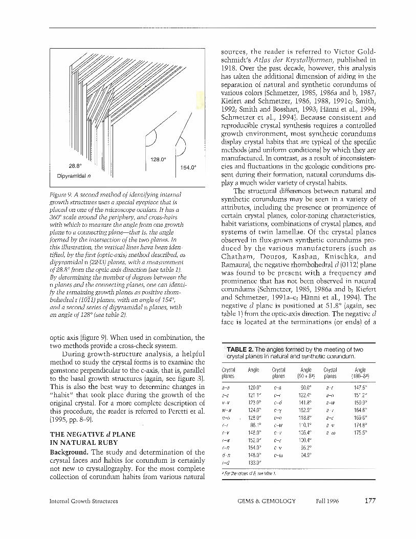
Dipyramidal n ' ' 1 1
Figure 9. A second method of identifying internal growth structures uses a special eyepiece that is placed on one of the microscope oculars. It has a 360' scale around the periphery, and cross-hairs with which to measure the angle from one growth plane to a connecting plane-lhat is, the angle formed by the intersection of the two planes. In this illustration, the vertical lines have been iden- tified, by the first (optic-axis) method described, as dipyramidal n (2243) planes, with a measurement of 28.8'from the optic axis direction (see table 1). By determining the number of degrees between the n planes and the connecting planes, one can identi- fy the remaining growth planes as positive thorn- bohedial r (1011) planes, with an angle of 154O, and a second series of dipyramidal n planes, with an angle of 128' (see table 2).
optic axis (figure 9). When used in combination, the two methods provide a cross-check system.
During growth-structure analysis, a helpful method to study the crystal forms is to examine the gemstone perpendicular to the c-axis, that is, parallel to the basal growth structures (again, see figure 3). This is also the best way to determine changes in "habit" that took place during the growth of the original crystal. For a more complete description of this procedure, the reader is referred to Peretti et al. (1995, pp. 8-9).
THE NEGATIVE d PLANE IN NATURAL RUBY Background. The study and determination of the crystal faces and habits for corundum is certainly not new to crystallography. For the most complete collection of corundum habits from various natural
Internal Growth Structures
sources, the reader is referred to Victor Gold- schmidt's Atlas der Krystallformen, published in 19 18. Over the past decade, however, this analysis has taken the additional dimension of aiding in the separation of natural and synthetic corundums of various colors (Schmetzer, 1985, 1986a and b, 1987; Kiefert and Schmetzer, 1986, 1988, 1991c; Smith, 1992; Smith and Bosshart, 1993; Hanni et al., 1994; Schmetzer ct al., 1994). Because consistent and reproducible crystal synthesis requires a controlled growth environment, most synthetic corundums display crystal habits that are typical of the specific methods (and uniform conditions) by which they are manufactured. In contrast, as a result of inconsisten- cies and fluctuations in the geologic conditions pre- sent during their formation, natural corundums dis- play a much wider variety of crystal habits.
The structural differences between natural and synthetic corundums may be seen in a variety of attributes, including the presence or prominence of certain crystal planes, color-zoning characteristics, habit variations, combinations of crystal planes, and systems of twin lamellae. Of the crystal planes observed in flux-grown synthetic corundums pro- duced by the various manufacturers (such as Chatham, Douros, Kashan, Knischlza, and Ramaura), die negative rhombohedra1 d (0112) plane was found to be present with a frequency and prominence that has not been observed in natural corundums (Schmetzer, 1985, 1986a and b; IQefert and Schmetzer, 1991a-c; Hanni et al., 1994). The negative d plane is positioned at 51.8' (again, see table 1) from the optic-axis direction. The negative d face is located at the terminations (or ends) of a
TABLE 2. The angles formed by the meeting of two crystal planes in natural and synthetic corundum.
Crystal Angle Crystal Angle Crystal Angle planes planes (90 + ¤a planes (180-Sa)
a-a 120.0Â c-a 90.0' a-r 147.6O z-z 121.1Â c-r 122.4' a-n 151.2O v-v 123.0Â c-d 141.8O a-w 159.g0 w-w 124.0Â c - y 162.5O a-v 164.6O n-n . 128.0Â c-n 118.8O a-z 169.6O r-r 86.1Â c-w llO.1Â a-v 174.8O r-v 148.0' c-v 105.4O a-co 175.5O r-w 152.0' c-z 100.4O r-n 154.0' c-v 95.2' d-n 148.0Â c -m 94.5O r-d 133.0'
a For the values 016, see table 1.
GEMS & GEMOLOGY Fall 1996

corundum crystal, extending from the basal pina- coid c (OOOl), between two dipyramidal or prism faces, and opposite a positive rhombohedral r (1011) face (figure 10). This crystal face has been reported historically in natural corundum (Bauer, 1896; Dana and Dana, 1904; Goldschmidt, 1918; Bauer and Schlossmacher, 1932). However, it appears that Max Bauer (1896) is the only source where a ruby crystal with a negative rhombohedral d (0112) face was actually examined and illustrated. The other refer- ences appear to be citing Bauer (1896) as their source of the information. In the more modem literature, the negative d face has been described as represent- ing a subordinate crystal form that, if present in nat- ural corundum, would be very small (Schmetzer, 1986a). However, no references can be found in the modem literature to the observation of a negative rhombohedral d (0112) plane on or in a natural ruby. This has led to the suggestion that the presence of a more dominant negative d plane, which is common- ly found in synthetic ruby, can be used as an indica- tion of synthetic origin [Schmetzer, 1985, 1986a and b; Kiefert and Schmetzer, 1991a-c).
As part of the gemological examination of sever- al hundred rubies, the author used internal growth- structure analysis, incorporating the combination of both methods described previously. These analyses revealed the presence of subordinate and, in some
Figure 10. These diagrams illustrate the position of the negative rhombohedral d (0112) and other crystal faces in the mor- phology of natural and synthetic wrun- dum. The drawing on the leh. recreates the probable original crystal habit for the 4-52 ct natural nzby described in this article, with the optic axis of the crystal inclined slightly from the vertical; the drawing below is of the same crystal viewed paral- lel to the optic axis (to illustrate how differ- ent crystal planes may look at different ori- entations in the three-dimensional crystal). Note the location of the negative d face from the terminations, or ends, of the crys- tal and between two n faces. On the Domos flux-grown synthetic ruby crystal shown on the right, the negative d face also connects to the positive r face, as well as to the c and n faces. Note how the relative prominence of the various crystal faces can dramatically affect the overall appearance of the crystal. The presence of faces other than c, r, n, and d suggests natural origin.
cases, dominant negative rhombohedral d (0112) planes in rubies that other tests proved were natural.
Materials and Methods. A total of eight natural rubies, between 0.15 ct and more than 25 ct, were identified with the negative rhombohedra1 d (0112) crystal plane as part of their original habit (table 3). Two had been purchased in northern Vietnam by Dr. Eduard J. Gubelin (Lucerne, Switzerland) and Mr. Saverio Repetto (previously director of FIN- GEMS, Chiasso, Switzerland)-1.34 and O. 15 ct, respectively-and had been represented to them as originating from the LLIC Yen mining region. Two others (7.03 and 25.55 ct) were reportedly from the Mogok Stone Tract in Myanmar, according to the clients who submitted them to the Gubelin Gemmological Laboratory for testing. The remain- ing four were also submitted to the Gubelin Gemmological Laboratory for examination, but without any indication as to their source.
A standard refractometer, desk-model spectro- scope, and electronic scale equipped with the neces- sary attachments for hydrostatic specific gravity measurements were used to determine that the eight samples were ruby. As part of the routine examination, as well as once the negative d planes were identified, extensive tests were conducted to confirm that the stones were indeed natural. To
178 Internal Growth Structures GEMS & GEMOLOGY Fall 1996

establish their natural origin by means of their inter- nal features, a binocular microscope equipped with a darkfield light source was used in conjunction with fiber-optic lighting. Both of the methods described above were used to analyze the internal growth structures and twinning characteristics. Semi-quan- titative chemical analysis was performed using a Spectrace TN5000 energy-dispersive X-ray fluores- cence (EDXRF) spectrometer with a special measur- ing routine for corundum developed by Professor W. B. Stem of the University of Basel.
Results. The refractive indexes (np = 1.760-1.764, no = 1.769-1.772; birefringence of 0.008-0.009), visible- range spectra (C6+ absorption bands), and specific gravity (3.98-3.99) were consistent with known properties for ruby. In addition, each of the stones had a combination of inclusion features, twinning, habit, and trace-element concentrations that provid- ed proof of their natural origin (again, see table 3).
Among the natural inclusion features observed in these rubies were transparent, colorless, and whitish mineral inclusions; unaltered and thermally altered healed fractures; zones of dense, unaltered nitile needles (figure 11); and rutile needles that were broken as a result of heat treatment. Also noted were
very fine-grained whitish clouds, "cross-hatch" or "flake-like" inclusion patterns, as well as "antennae- like" intersecting stringer formations (figure 12) and long, fine, needle-like tubules along the intersection of two or more systems of twin lamellae (commonly referred to as "boehmite needles").
When the internal growth structures provided enough information to recreate the crystal habit, typically two or more dipyramidal crystal and/or prism planes, combined with the basal and rhombo- hedral crystal planes, were present (figure 13; see also figure 10). The combinations of these inclusion features and internal growth structures alone pro- vided sufficient evidence of the natural origin of the rubies described.
Observation of the Negative Rhombohedra1 d (0112) Plane. In the eight natural rubies described in this article, the negative d planes ranged from subordi- nate through dominant, sometimes within the same stone. The negative d plane in the 1.34 ct ruby var- ied slightly in prominence from subordinate to inter- mediate during the growth of the gem (figure 14). This ruby also had dipyramidal w planes, dipyrami- dal z planes (of varying size), positive rhombohedra1 r, and basal pinacoid c planes.
--
TABLE 3. P r o p e r t i e s and internal c h a r a c t e r i s t i c s of the eight natural rubies w i t h t h e d (0112) plane.
Property1 Stone number
Characteristic 1 2 3 4 5 6 7 8
Carat weight 0.15 1.34 2.53 4,51 6.10 7.03 10.07 25.55 Inclusions Transparent Rutile needles, Thermally altered Slringer patterns Flake-like and Transparent and Dissolved Clusters of small
colorless crystals, healed fractures healed fractures cloud patterns, cross-hatch whitish crystals, rutile needles, transparent very fine grained rutile needles, cloud patterns, dissolved boehmite" needles, colorless crystals, whitish clouds, transparent thermally altered rutile needles, thermally altered rutile needles, short rutile needles colorless cryslals, healed fractures thermally altered healed fractures healed fractures
"boehmite" needles healed fractures Evidence of No No Yes No Yes Yes Yes No heat treatment Twinning None 1 system None 2 systems 1 system 1 syslem 2 systems None parallel to r Growth z c-w-z c-z-ffl or v c-n-z c-n-z C-d c-n-a c-n-w or v structures rand d rand d rand d rand d rand d rand d and d d plane Intermediate Subordinate Subordinate Subordinate Subordinate to Dominant Dominant Subordinate
dominant Chemistry
A I A 99.7 99.5 98.5 99.2 99.3 99.5 99.0 98.9 TiO, 0.014 0.016 0.031 0.050 0.022 0.035 0.044 0.024 vzo5 0.032 0.051 0.027 , 0.016 0.016 0.016 0.034 0.108 Crz03 0.210 0.256 0.899 0.691 0.612 0.41 3 0.733 0.528 Fezoa 0.038 0.093 0.018 0.023 0,012 0.003 0.006 0.009 Gazo3 0,008 0.01 4 0.001 0.005 0.004 0.003 0.006 0.018
Internal Growth Structures GEMS & GEMOLOGY Fall 1996 179
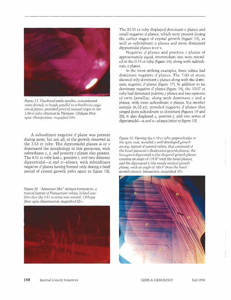
The 25.55 ct ruby displayed dominant c planes and small negative d planes, which were present during the earlier stages of crystal growth (figure 15), as well as subordinate n planes and more dominant dipyramidal planes co or v.
Negative d planes and positive r planes of 1 approximately equal, intermediate size were record- ed in the 0.15 ct ruby (figure 161, along with subordi- nate z planes.
In the most striking examples, three rubies had dominant negative d planes. The 7.03 ct stone showed only dominant c planes along with the domi- nant negative d planes (figure 17). In addition to its dominant negative d planes (figure 18), the 10.07 ct ruby had dominant positive r planes and two systems of twin lamellae, along with dominant c and a
Figure 11. Unaltered rutile needles, concentrated planes, with more subordinate n planes. Yet another more densely in bands parallel to subordinate nega- tive d planes, provided proof of natural oligin in the sample (6.10 ct), revealed negative d planes that
1.34 ct ruby obtained in Vietnam. Oblique fiber- ranged from subordinate to dominant (figures 19 and optic illumination, magnified 20x. 20); it also displayed c, positive r, and two series of
dipyramidal-n and z-planes (refer to figure 13).
A subordinate negative d plane was present during most, but not all, of the growth observed in the 2.53 ct ruby. The dipyramidal planes ft) or v dominated the morphology of this gemstone, with subordinate c, z, and positive r planes also present. The 4.51 ct ruby had c, positive r, and two different dipyrainidal-n and z-planes, with subordinate negative d planes having formed only during a brief period of crystal growth (refer again to figure 10).
Figure 12. "Antennae-like" stringer formations, a typical feature of Vietnamese rubies, helped con- fum that the 4.51 ct stone was natural. Oblique fiber-optic illumination, magnified 22x,
Figure 13. Viewing the 6.10 ci ruby perpendicular 10 the optic axis, revealed a well-developed growth zoning, typical of natural rubies, that consisted of the basal pinacoid c (horizontal growth planes), the hexagonal dipyramid n (the diagonal growth planes creating an angle of 118.8Owith the basalplanes), and the dipyramid z (the nearly vertical growth planes, with an angle of 100.4O from the basal growth planes). Immersion, magnified 1 Ox.
180 Internal Growth Structures GEMS & GEMOLOGY Fall 1996

Figure 14. The negative d planes in this 1.34 ct Vietnamese ruby varied in size slightly during the stages of growth that are visible in the faceted stone, but for the most part they were subordinate. The brownish bands following the growth structures are concentrations of short rutile needles. Also notice the sharp horizontal line, which is a twin plane par- allel to a positive r plane. Immersion, magnified 15x.
DISCUSSION Since this author first identified the negative rhoin- bohedral d (0112) plane in a natural ruby (Smith, 1992), he has identified this crystal plane in other samples. Statistically, however, this structural fea- ture remains very rare, having been observed in less than 1 % of the several hundred corundum samples (primarily ruby and blue sapphire) measured to date by the author. The term corundum is used in this context, because the author did identify the negative d plane in a natural blue sapphire loaned by Dr. H. A. Hanni, of the Swiss Gen~inological Institute (SSEF), Basel; this stone also reportedly originated from northern Vietnam. Determining the conditions under which the negative d plane formed in these samples is beyond the scope of this research; we can only surmise that they must have been very special.
To use the presence of the negative d plane to separate natural and synthetic rubies, careful inter- pretation of the growth features present is para-
mount. The negative d plane (especially as a doini- nant feature) remains more common in flux-grown synthetic rubies than in natural rubies. However, the entire collection of structural features should always be used in combination with a careful analy- sis of the other inclusion features, as well as with the information learned from a chemical or possibly infrared spectral analysis. Whereas the basal pina- coid c and the positive rhombohedra1 r planes are typically seen in both natural and synthetic rubies, n is the only dipyramid seen in synthetic rubies. Natural rubies typically contain one or any combi- nation of a, (o, v , z, v, w, or n.
Aside from the various inclusion features pre- sent, it was possible to identify seven of the eight
Figure 15. Basal pinacoid c planes dominated the growth structures seen in this 25.55 ct naturalruby, which was reportedly from Burma (Myanmar). The subordinate negative d planes were more prominent during the earlier stages of this gemstone's growth (creating an angle of 141.S0). The dark bands are concentrations of rutile needles oriented parallel to the growth planes. Immersion, magnified 15x.
Internal Growth Structures GEMS & GEMOLOGY Fall 1996

Figwe 16. Intermediate negutive d planes are easi- l y seen in this 0.15 ct Vietnamese ruby, connected to positive r planes. The angle created at the junc- tion is 133.0'; however, the complimentary angle is rdso readily seen at 47.0' (180 - 133 = 47). Immersion, magnified 35 x.
rubies in the sample population (the exception was the 7.03 ct stone) as natural by the presence of inter- nal growth structures (again, see table 3) that have not been seen in flux-grown synthetics. Conse- q~~ently, if a negative d plane is seen in a ruby, then it is important to look also for the hexagonal dipyra- mid and prism crystal planes. If, in addition to the negative d plane, only c, positive r, and/or n are observed, care must be taken: Although this suite of features is typical for flux-grown synthetic rubies, it may also occur in natural rubies. If no characteristic inclusions are present, the use of analytical tech- niques such as EDXRF chemical analysis (see, e.g., Stern and Hanni, 1982) or infrared spectroscopy (see, e.g., Smith, 1995) is advised. If additional dipyramid or prism planes are present, then natural ruby is indicated. In addition, the negative rhombohedra1 y (0175) plane, located at 72.S0 from the optic axis, is
Figure 17. The most striking example comes from a 7.03 ct ruby, reportedly from Burma (Myaamar), in which the only growth structures present con- sisted of dominant c planes and dominant nega- tive d planes, which created an angle of 141.8'. Immersion, magnified 18x.
still considered indicative of a synthetic ruby in those very rare situations where i t is present (Schmetzer, 1985, 1986a and b; Kiefert and Schmet- zer, 1991a-c).
If a negative d plane is detected in a ruby of sus- picions identity, then twinning characteristics can also provide important clues (Kiefert and Schmetzer,
Figure 18. Dominant negative d planes are seen in this 10.07 ct natural ruby, creating an angle of 233.0' with dominant positive r planes. The "checkerboard" appearance of intersecting lines is the result of twinning parallel to two positive r planes, forming angles of nearly 90'. Immersion, magnified 9x.
182 Internal Growth Structures GEMS & GEMOLOGY Fall 1996

Figure 19. The negative d planes in this 6.10 ct natu- ral ruby ranged from subordinate to dominant. This view shows a subordinate form of negative dplane with dominant c planes. Immersion, magnified l ox .
1986, 1988; Kiefert, 1987; Schmetzer, 1987, 1988). Twin planes parallel to the positive r planes [com- monly referred to as "laminated twinning") are common in natural rubies, but they may also be present in flux-grown synthetic rubies produced by Kashan (and, less commonly, i n those from Chatham or produced by the Verneuil method). In synthetic rubies, however, only rarely will the twin planes intersect one another. I11 contrast, twinning in natural rubies frequently has a "checkerboard" or "lattice work" appearance (again, see figure 18; Schmetzer, 1987). Other forms of twinning observed in natural and synthetic corundum can also aid in this separation (e.g., Kiefert, 1987; Schmetzer, 1988; Schmetzer et al., 1994; Hanni et al., 1994).
With regard to how the presence of the negative d plane may relate to source determinations, two of the rubies (1.34 and 0.15 ct) were purchased in Vietnam, and three others (2.53, 4.51, and 6.10 ct) revealed internal features typical of Vietnamese rubies. The suppliers of two of the remaining rubies (7.03 and 25.55 ct) indicated that they came from Myanmar. The author was unable to determine the probable source location of the 10.07 ct ruby. It is interesting that due negative d plane noted by Bauer (1896) also was reportedly in a natural ruby from Burma [now Myanmar). Therefore, it can be stated that to date the negative d plane has been observed in rubies from only two sources: Vietnam [Luc Yen) and Myanmar (Mogolz Stone Tract). Whereas the author has examined five to 10 times as many Mogolc as Vietnamese rubies, he has observed this plane more frequently in the Vietnamese stones.
Figiize 20. The 6.10 ct ruby also displayed dominant negative d planes as the stone was rotated to view additional growth-structure characteristics. Immersion, magnified 8x.
CONCLUSION The analysis of internal growth structures [internal indicators of crystal habit formation) in fashioned gemstones has been increasing in importance since it was first introduced to gemologists in 1985. The methods and principles involved can be learned and used by any gemologist with a minimum of special- ized equipment. With experience, the study of growth structures-through the identification of individual and pairs of crystal planes-can help distinguish between fashioned natural and synthetic gems as well as help classify gemstones from various deposits. While this article focuses on the identification of growth planes, observations of color zoning and twin- ning characteristics can also provide key information relating to a natural/synthetic distinction or prove- nance determination (see, e.g., Schmetzer, 1987; Smith and Surdez, 1994; Peretti et al., 1995; Smith et al., 1995; Hanoi et al., 1994).
According to earlier reports, the negative rhombo- hedral d (0112) plane was extremely rare innatural rubies and occurred only as a subordinate feature. However, tills article has detailed for the first time in the professional literature the occurrence of negative d planes as intermediate to dominant crystal planes in natural rubies. It is potentially relevant to locality determination that to date the negative d plane has been observed only in rubies from Vietnam and Myanmar. These findings reinforce the importance of not relying on any single growth feature as conclusive proof of the natural or synthetic origin of a ruby or sap- phire. Instead, identification and analysis of growth structures requires keen observation and interpreta- tion of all the observed crystallographic features.
Internal Growth Structures GEMS & GEMOLOGY Fall 1996

REFERENCES Bauer M. (1896) Ueber das Vorkommen der Rubine in Birma.
Neues Jahrbuch fur Mineralogie, Geologic und Palaeon- tologie, Vol. 2, pp. 197-238.
Bauer M., Schlossmacher K. (1932) E d e l s t e i n k d e , 3rd ed, Leipzig, Geimany, Bernhard Tauchnitz.
Crowningshield R., Hurlbut C., Fryer C.W. (19861 A simple pro- cedure to separate natural from synthetic amethyst on the basis of twinning. Gems a? Gemology, Vol. 22, No. 3, pp. 130-139.
Dana J.D., Dana E.S. (1904) The System of Mineralogy, 6th ed. John Wiley and Sons, New York, London.
Goldschmidt V. (19181 Atlas der Kryslallformen. Vol. 5. Carl Winters Universitatsbuchhandlun~. Heidelberg. Germany.
Hinni H.A., Schmetzer K. (1991) ~ e w r u b i e s from the ~ o i o ~ o r o area, Tanzania. Gems a) Gemology, Vol. 27, No. 3, pp. 156-167.
Hanni H.A., Schmetzer K., Bemhardt H-J. (1994) Synthetic rubies by Douros: A new challenge for gemologists. Gems a? Gemology, Vol. 30, No. 2, pp. 72-86.
Hofer S.C. (1985) Pink diamonds from Australia. Gems e>) Gemology, Vol. 21, No. 3, pp. 147-155.
Kane R.E. (1980) The elusive nature of graining in gem-quality diamonds. Gems a) Gemology, Vol. 16, No. 9, pp. 294-314.
Kane R.E. (1987) Three notable fancy-color diamonds: Purplish- red, purple-pink, and reddish-purple. Gems eJ Gemology, Vol. 23, No. 2, pp. 90-95.
Kiefert L., Schmetzer K. (1986) Morphologie und Zwillings- bildung bei synthetischen blauen Saphiren von Chatham. Zeitschrift der Deutschen Gemmologischen Gesellschuft, Vol. 35, NO. 314, pp. 127-138.
Kiefert L. 11987) Mineralogische Untersuchumen zur ~har i tk te r ; s i~ ' rbn~ und rln-terscheiilung ~citiirlichcr und Synthetischer Saphire. Diplomarheit Universitit Heidelberg, Germany, 203 pp.
Kiefcrt L., Schmetzer K. (1987) Blue and yellow sapphire from Kaduna Province, Nigeria. Journal of Gemmology, Vol. 20, NO. 7-8, pp. 427442.
Kiefert L., Schmetzer K. (1988) Morphology and twinning in Chatham synthetic blue sapphire, fotirnal of Gemmology, Vol. 21, No. 1, pp. 16-22.
Kiefert L., Schmetzer K. (1991a) The microscopic determination of structural properties for the characterization of optical uni- axial natural and synthetic gemstones, part 1: General consid- erations and description of the methods. Journal of Gemmology, Vol. 22, No. 6, pp. 344-354,
Kiefert L., Schmetzer K. (1991b) The microscopic determination of structural properties for the characterization of optical uni- axial natural and synthetic gemstones, part 2: Examples for the applicability of structural features for the distinction of natural emerald from flux-=own and hvdrothermallv-mown , " synthetic emerald. Journal of ~emmolo&, Vol. 22, No. 7, pp. 427-438.
Kiefert L., Schmetzer K. (1991~) The microscopic determination of structural properties for the characterization of optical uni- axial natural and synthetic gemstones, part 3: Examples for the applicability of structural features for the distinction of natural and synthetic sapphire, ruby, amethyst and citrine. Journal of Gemmology, Vol. 22, No. 8, pp. 471482.
Koivula J.I., Fritsch E. (1989) The growth of Brazil-twinned syn- thetic quartz and the potential for synthetic amethyst twinned on the Brazil law. Gems a? Gemology, Vol. 25, No. 3, -. . pp. 159-164.
Lind T., Schmetzer I<., Bank H. (1986) Blue and green beryls
(aquamarines and emeralds) of gem quality from Nigeria. Journal of Gemmology, Vol. 20, No. 1, pp. 40-48.
Peretti A., Smith C.P. (1993) An in-depth look at Russia's hydrothermal synthetic rubies. )ewelSiam, Vol. 4, No. 2, pp. 76-102.
Peretti A., Schmetzer K., Bernhardt H-J., Mouawad F. (1995) Rubies from Mong HSLI. Gems o) Gemology, Vol. 31, No. 1, pp. 2-26.
Rooney M-L.T., Welboum C.M., Shigley J.E., Fritsch E., Rehiitz I. (1993) De Beers near colorless-to-blue experimental gem-qual- ity synthetic diamonds. Gems el Gemology; Vol. 29, No. 1, pp. 3845.
Schmetzer K. (1985) Ein verbesserter Probenhalter und seine Anwendung auf Probleme der Unterscheidung natiirlicher und synthetischer Rubine sowie natiirlicher und synthetisch- er Amethyste. Zeitschrjft der Deutschen Gemmologischen Gesellschaft, Vol. 34, No. 1, pp. 30-47.
Schmetzer K. (1986a) An improved sample holder and its use in the distinction of natural and synthetic ruby as well as natural and synthetic amethyst. Journal of Gemmolofw, Vol. 20, No. . . -. . 1, pp.20-33.
Schmetzer K. (1986b) Natiirliche -and synthetische Rubine- Eisenschaften und Bestimmum. Schweizerbart, Stuttgart.
~chmetzer K.' (1987) On twinningin natural and synthetic flux- grown ruby. Journal of Gemmology, Vol. 20, No. 5, pp. 294-305.
Schmetzer I<. (1988) A new type of twinning in natural sapphire. Journal of Gemmology, Vol. 21, No. 4, pp. 218-220.
Schmetzer K., Bemhardt H-J., Biehler R. (1991) Emeralds from the Ural Mountains, USSR. Gems o) Gemology, Vol. 27, No. 2, pp. 86-99.
Schrnetzer K., Smith C.P., Bosshart G., Medenbach 0. (1994) Twin- ning in Ramaura synthetic rubies. Journal of Gemmology, Vol. 24, NO. 2, pp. 87-93.
Shigley J.E., Fritsch E., Reinitz I., Moon M. (1992) An update on Sumitomo gem-quality synthetic diamonds. Gems a) Gemology, Vol. 28, No. 2, pp. 116-122.
Shigley J.E., Fritsch E., Koivula J.I., Sobolev N.V., Malinovsky I.Y., Pal'yanov Y.N. (1993) The gemological properties of Russian gem-quality synthetic yellow diamonds. Gems d Gemology, Vol. 29, No. 4, pp. 228-248.
Smith C.P. (1992) Contributions to the crystal growth analysis of natural and synthetic rubies: Identification of a dominant neg- ative rhombohedra1 "d" plane (01T2) in natural ruby. 60th Anniversary Proceedings, Zeitschriit der Deutschen Gemmologischen GeseUschafi, Vol. 41, No. 4, pp. 182-183.
Smith C.P., Bosshart G. (1993) New flux-grown synthetic nibies from Greece. JewelSiam, Vol. 4, No. 4, pp. 106-1 14.
Smith C.P., Surdez N. (1994) The Mong Hsu ruby: A new type of Burmese ruby. fewelsiam, Vol. 4, No. 6, pp. 82-98.
Smith C.P. (1995) Contribution to the nature of the infrared spec- trum for Mong Hsu rubies. Journal of Gemmology, Vol. 24, No. 5, pp. 321435.
Smith C.P., Kammerling R.C., Keller A.S., Peretti A., Scarratt K.V., Khoa N.D., Repetto S. (1995) Sapphires from southern Vietnam. Gems <t> Gemology, Vol. 31, No. 3, pp. 168-186.
Stem W.B., Harmi H.A. (1982) Energy dispersive X-ray spectrome- try: a non-destructive tool in gemmology. journal of Gemmology, Vol. 18, No. 4, pp. 285-296.
Sunagawa I. (1992) Morphology aspects of diamonds, natural and synthetic, stable and metastable growth. 60th Anniversary Proceedings, Zeitschrift der Deutschen Gemmologischen Gesellschaft, Vol. 41, No. 4, pp. 184-185.
184 Internal Growth Structures GEMS & GEMOLOGY Fall 1996

EVERYTHING UNDER THE S U N IN GEMOLOGY A N D JEWELRY MANUFACTURING ARTS EDUCATION
CIA ALUMNI & ASSOCIATES EVENTS C I A President's Award Recept ion o n Jan . 3 1
Genera l Membersh ip Breakfast Mee t ing o n Feb. 1
Alumni Gala & Awards Evening o n Feb. 2
EXHIBITS T o find out what's new in C I A G E M Instruments, t h e CIA
Bookstore, Gems & Gemology, C I A Education, GIA ARMS, and
Alumni Associates, s t op by the C I A booths a t t h e AGTA
GemFair in t he Convent ion Cen te r Galleria a n d t h e G L D A
Show in the Hol iday Inn Broadway Lobby spaces 6 & 7.
For more information
about CIA classes and
seminars in Tucson,
Cal l Today Toll-Free:
(800) 42 1-7250 ext. 269
(Alumni Events ext. 724)
Outside the U.S., call:
( 3 10) 829-299 1 ext. 269
o r FAX: ( 3 10) 453-7674
CIA TUCSON '97 CLASSES AND SEMINARS Janua ry 27-February 4, 1997
Topics include: Diamond Grading Geni Identification Colored Stone Grading Detecting Synthetic Diamonds Detecting Treated Gems Identifying Challenging Synthetics Gem ID Challenge with John Koivula CIA ARMS, Your Roadmap to
Greater Profitability CIA Research; Year in Review Introduction to Insurance
Replacement Appraisals Working with Wax Wax Carving Techniques Bench Tricks
Advanced Fabrication Mass Finishing Techniques-Texture: Flush, Bezel, Gypsy Setting
Plus! NEW in '97: Working with Platinum Chain Making Working with Precious
Casting Stones in Place Channel Setting with
the AIISet Tool crap Preparation

By Karl Schmetzer, Adolf Pesetti, Olaf fvledenbacl~, and Heinz-Jurgen Bernl~ardt
Synthetic alexandrite is being flux- grown in Rz~ssia in a molybdenum-, bismuth-, and germanium-bearing sol- vent by means o{ the reverse-tempera- ture gradient method. Characteristic properties include habit, twinning, growth patterns, residzial flux inclu- sions, trace-element contents, chemical zoning, color zoning, and spectroscopic feat~zres in the visible and infrared ranges. The relationship between pro- duction technique and characteristic properties is discussed, and diagnostic properties that can be used to distin- guish these synthetics from natural alexandrite are disclosed.
h e alexandrites are even rarer than fine rubies! sap- phires, and emeralds. The major factors determining (F price are size! clarity! brilliancy! color in daylightl color
change in artificial light! and country of origin. The finest alexandrites are characterized by a lively and intense green color in daylight with a prominent color change to purplish red or redhsh purple in incandescent l&t. The most presti- gious source of natural alexandrites is Russia! specifically the Ural mountains, where they were first discovered. Fine alexandrites occasionally appear at international auctions. For example! a 31 ct alexandrite sold for almost US$185,000 at Christie's May 1992 auction in Geneva. Dealers in Idar- Oberstein report the sale of fine! large (over 5 ct) alexandrites for $101000-$201000 per carat, and even higher for exception- al stones (R. Guerlitz and A. Wild! pers. comm.r 1996).
During the past 10 years! new deposits of natural alexan- drite have been found in Minas Gerais! Brazil (Banlz et al.! 1987; Proctorl 1988; Cassedanne and Roditi, 1993; Karfunlzel and Wegner! 1993); in Orissa and Madhya Pradesh! India [Patnailz and Nayalzl 1993; Newlay and Pashine! 1993); and! most recently! near Songea in southern Tanzania (see ''News on the Songea Deposit . . .", 1995; Kammerling et al.! 1995). In addition! gem alexandrites are still being recovered from the historic emerald deposits of the Ural Mountains (Eliezri and Kremlzowl 1994; Laslzovenlzov and Zhernalzovl 1995).
As greater quantities of gem alexandrite enter the mar- lzet! significant amounts of faceted alexandrites are being submitted to gemological laboratories for testing. occasion ally^ distinguishing natural from synthetic has been difficult! notably for flux-grown syntheticsl but especially when a specimen lacks diagnostic mineral incl~~sions (see Banlz et al.! 1988; Hem and Banlzl 1992; Kammerhg, 1995). These difficulties are caused by the similarity of growth structures and healing "feathers" in natural alexandrites from different localities to residual flux feathers in flux- grown synthetic alexandrites. In addition! hematite platelets in natural alexandrites sometimes resemble platinum inclu- sions in their flux-grown synthetic counterparts.
186 Synthetic Alexandite GEMS & GEMOLOGY Fall 1996

The Russian-produced synthetic alexandrites (figure 1) can imitate the highest-quality nat~lral alexandrites-such as those from the Ural moun- tains. Yet some natural alexandrites have sold for up to 300 times as much as their synthetic counterparts. Consequentlyl these synthetic alexandrites occasion- ally are misrepresented in the trade as Uralian alexandrites. One of the authors (A.P.) recently encountered two instances of synthetic alexandrites offered for sale as natural stones in Switzerland.
According to the voluminous scientific and patent literature available to the authors) synthetic alexandrite and synthetic chrysoberyl can be grown from the melt (Czochralslzil Ve rne~~ i l~ Bridgman) and floating-zone techniques)! hydr~thermally~ by the flux methodl and by chemical vapor deposition (for a good description of most of these modern crys- tal-growth techniq~~es~ see Kimura and Kitamural 1993). Because of such factors as prod~lction costs and the small crystals that result from some of these growth techniquesl gem-quality synthetic alexan- drites have been grown commercially and released to the market by just a few c~mpanies! which use the Czochralskil floating-zonel or flux method.
Two types of flux-grown synthetic alexandrite have been produced commercially for gem purpos-. es. Since the 1970s) Creative Crystals Inc. of San Ramon! California! has produced synthetic alexan- drite crystals by a method that uses a lithium
polymolybdate fluxl as described in the Cline and Patterson patent (1975).
The second type has been produced at various locations in the former USSR since the late 1970s or early 1 9 8 0 ~ ~ sing a method origmally developed at the Institute of Geology and Geophysicsl Siberian Branch of the Academy of Sciences of USSR in Novosibirslz. A few crystals grown by t h s method were given to one of the authors (K.S.) by Drs. A. Ya. Rodionov and A. S. Lebedev in 1988 and 1991. Preliminary results from the examinations of these samples were never published because of the very small sample base. That situation has changed. Considerable quantities (many lzilos) of rough
Synthetic Alexandite GEMS & GEMOLOGY Fall 1996
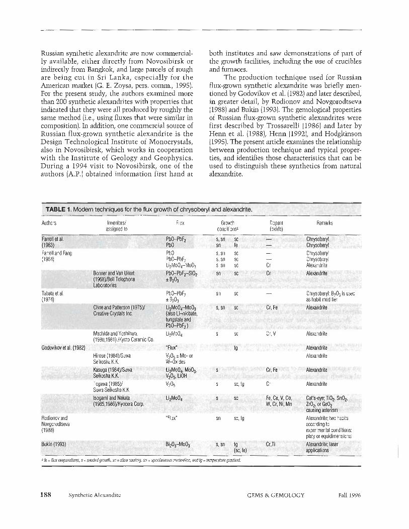
Russian synthetic dexandrite are now commercial- ly available, either directly froin Novosibirslz or indirectly from Banglzolzl and large parcels of rough are being cut in Sri Lanka, especially for the h e r i c a n inarlzet (G. E. Zoysal pers. comm.! 1995). For the present study, the authors examined more than 200 synthetic alexandrites with properties that indicated that they were all produced by roughly the same method (i.e,, using fluxes that were similar in composition]. In adhtion! one commercial source of Russian flux-grown synthetic alexandrite is the Design Technological Institute of Monocrystals, also in Novosibirslzl which works in cooperation with the Institute of Geology and Geophysics. During a 1994 visit to Novosibirslzl one of the authors (A.P.) obtained information first hand at
both institutes and saw demonstrations of part of the growth facilities, including the use of crucibles and furnaces.
The production technique ~lsed for Russian fl~x-grown synthetic alexandrite was briefly men- tioned by Godovilzov et d. (1982) and later described! in greater detail, by Rodionov and Novgorodtseva (1988) and Bulzin (1993). The gemologcal properties of R~issian flux-grown synthetic alexandrites were first described by Trossarelli (1986) and later by Henn et al. (19881, Henn (1992)! and Hodglzinson (1995). The present article examines the relationship between production technique and typical proper- ties, and identifies those characteristics that can be used to distinguish these synthetics froin natural alexandrite.
Authors Invenlorsl assigned to
Flux Growth Dopant Remarks conditionsa (oxide)
Farrell and Fang PbO s, sn sc - Chrysoberyl ( I 964) PbO-PbF2 s, sn sc - Chysoberyl
Li2Mo04-Moo3 s, sn sc Cr Alexandrite
Tabata et al. (1974)
- Chrysoberyl: B203 is used as habit modifier
Togawa (1985)l s sc, tg Cr Atexandrite Suwa Seikosha K.K
Rodionov and Novgorodtseva (I 988)
'Fluxm sn sc, tg Alexandrite; hvo habits according lo experimental cofldilions: ~ l a l v or eauidimensional
a /e = flux evaporalions, s =seeded growlh, sc =slow cooling, sn = sponlaneous nuclealion, and lg = lemperalure gmdienl.
Synthetic Alexandite GEMS & GEMOLOGY Fall 1996

Figure 2. Three main processes have been described for the flux growth of beryLlium-bearing oxides and silicates such as synthetic alexondrite and emerald: (A) slow cooling of a saturated melt, with seeded growth or growth by spontaneous nucleation; (B) seeded growth in a temperature gradient, with a growth zone above the dissolu- tion zone; And (C) seeded growth or growth by spontaneous n~~cleation in A reverse temperature gradient, with a growth zone at the bottom of the cnzcjble below the dissolution zone. Key: 1 = platin~zm crucible, 2 = flux melt, 3 = growing crystals, 4 = seed, 5 = platinum seed holder, 6 = nutrient, 7 = baffle, 8 = insulation, t l = temperalure in the upper part of the crucible, t2 = temperature in the lower part of the crucible. The circular arrows at the top of A and B indicate the possible rototion of the seed holder; arrows at the bottom of all three processes represent the possible crucible rotation. Adapted from Bulcin (1 993).
FLUX GROWTH OF SYNTHETIC ALEXANDRITE: HISTORY AND DEVELOPMENT Early 19th-century experiments in the flux growth of synthetic chrysoberyl were summarized by Elwell and Scheel (1975). More modem flux techniques to grow synthetic chrysoberyl and/or alexandrite start- ed in the 1960s (table 1). Most procedures use the slow-cooling technique (figure 2A). First! the solvent of flux and nutrient (A1203 + Be0 + color-causing dopants) is heated above the point at whch the flux liquefies and is then held at that temperature for a period sufficient to dissolve the nutrient oxides in the flux (Farrell and Fangl 1964). Next! the melt is cooled slowly at a constant rate untd the flux solidi- fies. Lastl the crystals that grew in the f l u during cooling are removed from the crucible by dissolving the flux (e.g.! in hot nitric acid). Common fluxes used for chrysoberyl and alexandrite are PbO-PbF2! Li2Mo04-Mo031 and V205 (see table 1). The tem- peratures at which the cooling process begins and ends vary according to the composition of the flw used. They generally range f r ~ m l35O0C to 8OO0C. Coohg rates are usually between 0.125OC and 3OC per hour. Both seeded growth and growth by spon- taneous nucleation are used (again! see figure 2A). Seed crystals may be natural or synthetic chryso- beryl or alexandrite. Cr2031 F%03! and/or V203 are used as dopants.
The morphology of synthetic chrysoberyl or alexandrite depends primarily on the composition of the f l u and not on the temperatures or c o o k gra- dients used. Tabata et al. (1974) demonstrated the hfluence of B203 on the habit of chrysoberyl grown from PbO-PbF2 solvents: They observed a distinct modification of habit from platy (flux without B203) to prismatic or equidimensional ( f l u with B203).
Isolated attempts to grow synthetic chrysoberyl or alexanclrite by the flux evaporation technique have had poor results (see Farrell et al./ 1963). In this methodl constant heating of the melt in open cru- cibles leads to supersaturation of the melt and the growth of crystals by spontaneous nucleation.
Godovikov et al. (1982) first mentioned the pos- sible growth of alexandrite by the temperature-gra- dient methodl which worlzs by creating a convec- tion current within the crucible. According to a Japanese patent application by Togawa (1985)1 the nutrient is placed at the bottom of the cruciblel where a certain temperature is reached and then maintained. A seed crystal is placed into the melt in the upper part of the cruciblel which is held at a temperature lower than that at the bottom of the crucible (figure 2B). As the nutrient dissolves into the solutionl circulation begins between the warmer and cooler areas in the crucible (convection cur- rents). When the solution with the nutrient reaches the cooler areal it becomes supersaturated and crys- tals begin to form. These different temperatures are
Synthetic Alexandite GEMS & GEMOLOGY Fall 1996

Figure 3. The Russian flux-grown synthetic alexandrite crystals examined were either single crystals (right, 9 x 7 mm) or cyclic pseudohexagonal twins (left, 12 x 11 mm), which are shown here in incandescent light. I1ho~o 0 GIA and Tino Hammid.
maintained! with the growth zone above the disso- lution zone! for weeks or even months.
Rocbonov and Novgorodtseva (1988) described a reverse temperature-gradient technique-in which the growth zone is located below the dissolution zone-for the growth of synthetic alexandnte. In this method! the nutrient is placed in the upper part of the cruciblel where a certain temperature is reached and then maintained) while the bottom of the cm- cible is held at a lower temperature (figure 2C; tem- peratures are in the same range as those noted above for the slow-cooling process). With this techniquel synthetic alexandrite crystals grow by spontaneous nucleation! ~isually in contact with the bottom of the crucible (Rodionov and Novgorodtse~a~ 1988)) although seeded growth [with a seed placed at the bottom of the crucible) is also possible (Bulunl 1993).
The solvent used in Russia is a complex bis- muth-molybdenum fl~lx! mainly composed of Bi203 and Moo3 (A. Ya. Rodionovl pers. comm.l 1988; Bukin 1993; confirmed during a visit by one of the authors [A.P.] to Novosibirsk in 1994).
The basic growth technique that was developed in Novosibirslz forms synthetic alexandrite crystals with two different habits-thin and platy or more isometric and equidimensional-depending on con- trolled change in the growth conditions (Rodionov and Novgorodtseval 1988). Growth rates of 0.13 to 0.35 min per day in different crystallographic direc- tions have been obtained. For example) a 14 x 8 x 9 mm crystal was grown by spontaneous nucleation over three months with this technique (Rodionov and Novgorodtse~a~ 1988). According to Bulzin
Synthetic Alexandite
(1993)/ crystals as large as 2-3 cm (over one inch) can be grown by spontaneous n~~clea t ion in a reverse-temperature gradient) and even larger sam- ples are possible with seeded growth.
MATERIALS AND METHODS In 1994! one of the authors (A.P.) purchased about 50 synthetic alexandrites that had been flux grown in Russia. These samples were selected in Bangkok from six lotsl each of which contained hundreds of synthetic alex'andrite crystals and represented thou- sands of carats of flux-grown material. In addition! R. Goerlitz of Ida-Oberstein) Germanyl loaned the authors a lot of about 150 rough crystals that he had purchased in Novosibirslz in 1993. This sample of more than 200 Russian flux-grown synthetic alexan- drites used for the present study also included mate- rial submitted by Novosibirslz scientists to one of the authors (K.S.) in 1988 and 1991. All of the origi- nal samples were rough crystals; the few faceted gems studied (see) e.g.) figure 1) were fashioned from rough from the Banglzolz and R. Goerlitz lots.
A b o ~ ~ t half of the crystals were fully developed single crystals or cyclic twins with one irregular pla- nar surface (figure 3). Compared to the smooth crys- tal faces! this irregular surface was somewhat rough and unevenj it probably represents the contact plane of the growing crystal with the bottom of the cru- cible (see the later discussion of growth conditions). Most of the balance of the samples had one irregular plane or surface that was obviously produced by sawing or brealzingl probably to remove some impure! non-gem-quality material or to separate the smgle crystals or twins from larger clusters. Seven smaller crystals (sizes up to 4 mm] were fully devel- oped without any irregular surface plane,
We performed standard gemological testing on about 40 of these crystals. To identdy the intemal growth planes and the external crystal faces! we stud- ied about 50 crystals with a Schneider horizontal (immersion) microscopel which had a specially designed sample holder as well as specially designed (to measure angles) eyepieces (Schmetzer! 1986; Kiefert and Schmetzer) 1991; see also Peretti et al.! 1995). In addition! we examined abo~~ t 10 samples with an opti- cal goniometer (an instrument used to measure crystal angles). By a combination of these methods! we identi- fied all crystal faces and the most characteristic growth patterns. We st~lcbed and photographed the inclusions and intemal structwal features using the Schneider immersion microscope (with Zeiss optics) and an Eiclzhorst vertical microscope (with Nilzon optics) and fiber-optic illumination.
GEMS & GEMOLOGY Fall 1996

Solid inclusions and solid phases on the surfaces of the crystals were characterized by X-ray powder diffraction analysis with a Gandolfi camera, by a Cambridge Instruments scanning electron micro- scope with an energy-dispersive X-ray detector (SEM-EDS), and by energy-dispersive X-ray fluores- cence analysis (EDXRF) using a Tracor Northern Spectrace TN 5000 system.
We also performed qualitative chemical analysis of 22 samples using the same EDXRF instrumenta- tion. For quantitative analysis of nine other samples, a CAMECA Camebax SX 50 electron microprobe was used. To evaluate nonhomogeneous chemical compositions of the alexandrite crystals, we mea- sured 2-5 traverses (of 40 to 140 point analyses each) across the samples. For more detailed information, we also had one scan with 625 point analyses.
Polarized absorption spectra in the visible and ultraviolet range were recorded for nine microscopi- cally untwinned single crystals with a Leitz-Unicam SP 800 double-beam spectrometer and a Zeiss mul- tichannel spectrometer. Infrared spectroscopy was carried out on 11 samples using a Philips PU 9800 FTIR spectrometer.
RESULTS Visual Appearance. The samples varied from slight- ly yellowish green to green and bluish green in day- light and from slightly orangy red to red and pur- plish red in incandescent light (again, see figures l and 3). No distinct color zoning was apparent in either the rough or faceted samples.
On the faces of some crystals, we observed a fine-grained white crust. In irregular cavities of other samples, we found a fine-grained gray or yel- lowish gray material.
Crystallography. All samples examined revealed an equidimensional habit, which was formed by three pinacoids a, b, and c; by four different rhombic prisms, designated s, m, x, and k; and by the rhom- bic dipyramid o (table 2). The seven small crystals that lacked rough or uneven faces were fully devel- oped single crystals (see, e.g., figures 4 and 5).
All of the crystals with one uneven face-and those crystals that were sawn or broken-had three dominant faces: the pinacoid a, the rhombic prism x, and the rhombic dipyramid o. Frequently, the rhombic prism 1i was also present, and the pinacoid c was subordinate. About 90% of these crystals were cyclic twins (figures 6 and 7), which consisted of three individuals twinned by reflection across the rhombic prism (03 1) and forming a pseudohexagonal
contact twin (figures 6 and 81. The remaining 10% of the samples were untwinned single crystals.
For those crystals that were not broken or sawn, the most frequently observed habit consisted of the a, x, o, and k faces (figures 6C and D). Also common was a habit formed by the three faces a, x, and o (fig- ure 6A). Crystals with an additional c pinacoid were somewhat rarer (see table 2 and figures 6B and E).
Most of the cyclic twins were somewhat dis- torted; that is, identical crystal faces varied in their respective sizes between the three individuals of the cyclic twin. Examples are shown in figures 6C and D, in which varying sizes were drawn for the rhoin- bic prism x. Consequently, a typical crystal of Russian flux-grown alexandrite is a combination of the two trillings drawn in figures 6C and D, with sizes of the x faces varying within the cyclic twin.
In a few single crystals with one irregular face, the pinacoid b and the rhombic prism m were also observed (see figure 5). In one of these single crystals, an additional rhombic prism i was also present (table 2).
Gemological Properties. Table 3 summarizes the gemological properties of the Russian flux-grown synthetic alexandrites examined. The values are more or less within the ranges published by others for crystals of this material (Trossarelli, 1986; Henn et al., 1988; Rodionov and Novgorodtseva, 1988; Henn, 1992; Buliin, 1993).
Specifically, these Russian synthetic alexan- drites are distinctly pleochroic. Their color change is
TABLE 2. Morphological crystallography of Russian flux-grown synthetic alexandrites.
Designation hklc TY pe Faces a (100) pinacoid
ba (010) pinacoid c (001) pinacoid sJ (120) rhombic prism ma (110) rhombic prism x (101) rhombic prism k (021) rhombic prism fb (011) rhombic prism o (111) rhombic dipyramid .........................................................
Faces Number of crvstals Habit a x 0 21
a x o c 7 a x o k 49 a x o c k 10
Characteristic ax 141' xx' 78' angles formed a0 137O 00' 8 6 O by two faces kk' 81.5' kk' 141.5' (re-entrant)
Observed only in single crystals. 6 Observed only in one single crystal. c Otienlalion 01 the unit cell lot the Millet indices: a = 4.43, b = 9.40, c = 5.48.
Synthetic Alexandite GEMS & GEMOLOGY Fall 1996 191
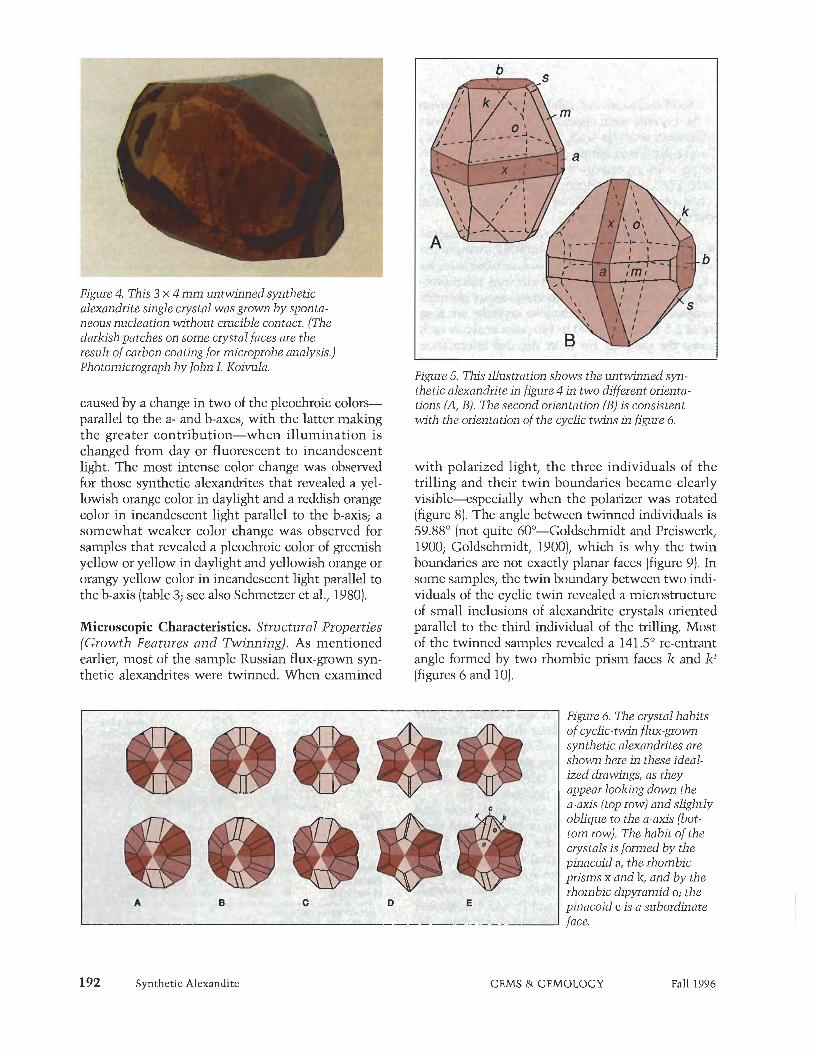
Figure 4. This 3 x 4 m m untwinned synthetic alexandrite single crystal was grown by sponta- neous nucleation without crucible contact. (The darkish patches on some crystal faces are the result of carbon coating for microprobe analysis.) Photomicrograph by John I. Koivula.
caused by a change in two of the pleochroic colors- parallel to the a- and b-axes, with the latter malcing the greater contribution-when illumination is changed from day or fluorescent to incandescent light. The most intense color change was observed for those synthetic alexandrites that revealed a yel- lowish orange color in daylight and a reddish orange color in incandescent light parallel to the b-axis; a somewhat weaker color change was observed for samples that revealed a pleochroic color of greenish yellow or yellow in daylight and yellowish orange or orangy yellow color in incandescent light parallel to the b-axis (table 3; see also Schmetzer et al., 1980).
Microscopic Characteristics. Structural Properties (Growth Features and Twinning). As mentioned earlier, most of the sample Russian flux-grown syn- thetic alexandrites were twinned. When examined
1 .cj;tts *K'lLiK+. rjB -Â¥ri 7̂ ÑÑ,-z Â¥*f +-ST .:I - . J , ' 5
Figure 5. This illustration shows the zintwinned syn- thetic alexandrite in figure 4 in two different orienta- tions (A, B). The second orientation (B) is consistent with the orientation of the cyclic twins in fwre 6.
with polarized light, the three individuals of the trilling and their twin boundaries became clearly visible-especially when the polarizer was rotated (figure 8). The angle between twinned individuals is 59.88' (not quite 60'-Goldschmidt and Preiswerlz, 1900; Goldschmidt, 1900), which is why the twin boundaries are not exactly planar faces (figure 9). In some samples, the twin boundary between two indi- viduals of the cyclic twin revealed a microstructure of small inclusions of alexandrite crystals oriented parallel to the third individual of the trilling. Most of the twinned samples revealed a 141.5' re-entrant angle formed by two rhombic prism faces k and k' (figures 6 and 10).
Figure 6. The crystal habits of cyclic-twin flux-grown synthetic alexandrites are shown here in these ideal- ized drawings, as they appear looking down the a-axis (top row) and shghtly oblique to the a-axis (bot- tom row). The habit of the crystals is formed by the pinacoid a, the rhombic prisms x and lz, and by the rhombic dipyramid o; the pinacoid c is a subordinate face,
Synthetic Alexandite GEMS & GEMOLOGY Fall 1996

Figure 7. This approximaiety 3 X 5.5 mm cyclic twin of Russian synthetic alexandrite reveals an irregular contact plane (below) with the crucible; the habit of the crystal is formed by a, x, and o \aces (see \iglue 6A).
The internal growth features of both the rough and faceted Russian synthetic alexandrites corre- sponded to the external morphology of the crystals. All single crystals or cyclic twins that showed one irregularly oriented uneven plane-that is, all sam- ples that grew in contact with the crucible- revealed distinct internal growth planes parallel to the four dominant faces a, x, k, and o.
In a view parallel to the crystals' a-axis (i.e., per- pendicular to the a pinacoid), growth planes parallel to different lz prism faces were visible in most of the
Figure 8. The three individuals and the twin bound- aries of this trilling are clearly visible when this cyclic twin of synthetic alexandrite is viewed paral- lel to the a-axis, using a polarizer and immersion. Magnified lox.
samples (about two out of three; again, see figures 6 and 10). Two characteristic angles were observed in this orientation: an angle of 81.5' formed by two lz prism faces of one individual, and a re-entrant angle of 141.5' formed by two lz faces of two individuals of the twin (see table 2). All of these I&' characteristic growth structures also were observed in the faceted synthetic alexandrites (figure 11).
In a view parallel to the b-axis (figure 124, a sec- ond characteristic growth pattern ax was observed in all samples. This consists of a pinacoids and x prism faces, which form a 78' angle (figure 13). By rotating the crystal approximately 29' about the a-axis (figure 12B), we saw a third characteristic growth pattern ao. Visible in all samples, it is formed by a pinacoids in combina- tion with o dipyramids (figure 14). In this case, the char- acteristic angle (formed by the two rhombic dipyramids o) measures 86'. So, three characteristic patterns of growth structures were observed in single crystals and cyclic twins of Russian synthetic alexandrites: ax and ao in all samples, and I&' in approximately two-thirds of the samples.
In about 10% of the single crystals and twins examined, we saw a distinct color zoning-an intense red core (in incandescent light) and a lighter red rim-with the microscope. These areas are sepa- rated by a somewhat rounded, very intense red boundary (figure 15). This was the only color zoning seen in any of the samples.
In those small single crystals that were obvious- ly grown without contact with the crucible (again,
TABLE 3. Gemological properties of Russian flux-grown synthetic alexandrites.
Property Observations
Day (fluorescent) light Incandescent light
Yellowish green or green or bluish green
Orangy red or red or purplish red
Purplish red Orangy yellow or yellowish orange or reddish orange Blue-green
Pleochroism X parallel to a-axis Reddish purple Y parallel to b-axis Greenish yellow or
yellow or yellowish orange
Z parallel to c-axis Blue-green Refractive indices
nx 1.740 -1.746 HZ 1.748 -1.755
Density (gIcrn3) 3.67-3.74 UV fluorescence
Long-wave Bright red Short-wave Weak red or inert
Synthetic Alexandite GEMS & GEMOLOGY Fall 1996

Figure 9. The twin boundaries in this cyclic twin of synthetic alexandrite show a distinct step-like structure. View almost parallel to the a-&; immersion, crossed polarizers, magnified 6 0 ~ .
Figure 10. Growth structures parallel to different lz prism faces form a characteristic angle of 81.5O; re-entrant angles of 141.5O are formed by two dif- ferent crystals of the cyclic twin. View parallel to the a-axis; immersion, magnified 3 5 ~ .
see figure 4), only very weak growth structures were found parallel to external crystal faces.
Inclusions. Various forms of residual flux were observed in many of the Russian synthetic alexan- drites. These include "feathers" or "fingerprints" that consist mainly of isolated droplets or dots, which could be confused with healing features in natural alexandrites. Occasionally, we saw two- phase inclusions of residual flux and spherical bub- bles, formed by shrinkage of the trapped flux as it cooled. Feathers of interconnecting tubes or chan-
Figure 11. The view parallel to the a-axis reveals characteristic growth structures parallel to the dif- ferent lz prism faces of the cyclic twin in this faceted flux-grown synthetic alexandrite. Immersion, magnified 45x.
194 Synthetic Alexandite
nels (figure 16) also were frequently seen. In some crystals, planar, almost continuous, thin films with- in a net-like or web-like (i.e., emanating outward from a central point) pattern of flux were observed (figure 17). Occasionally, birefringent refractive components were also found in these flux "nets" (figure 18). In many cases, the flux inclusions took the form of wispy veils (figure 19).
In some of the samples, we observed metallic inclusions (particles or needles). On the basis of EDXRF analyses of similar-appearing solid phases on the surfaces of some of the crystals, we identified these inclusions as platinum.
Chemistry. The EDXRF spectra of the faceted sam- ples and rough crystals with clean faces-that is, without any flux residue on the surface or in open pits or cavities-indicated varying amounts of Cr, V, Fe, Gal Gel Bi, and Mo (figure 20), as well as the expected Al. On the basis of these EDXRF results, we added Ge to the list of elements that we mea- sured with the electron microprobe. X-ray fluores- cence analysis also confirmed the presence of Sn, traces of which were detected in the course of the microprobe analyses.
Initial scans by electron microprobe revealed zonal variations of all minor-to-trace elements, but zoning of Cr, Fe, and Ge-and sometimes V-was particularly evident. A detailed scan (about 3 mm in length, with 625 point analyses) across one sample (see table 4, sample 7) revealed a distinct zoning and correlation of Cr, Fe, and Ge. In this sample, Ge showed a positive correlation with Fe and a negative correlation with Cr. In other words, when Ge increased, Fe also increased, but Cr decreased as
GEMS &. GEMOLOGY Fall 1996

growth conditions changed. In other samples, how- ever, a negative correlation between Ge and Fe was observed; that is, when Ge increased, Fe decreased. Two synthetic alexandrites had a positive correla- tion between V and Fe, and one sample showed a positive correlation between Cr and Ge.
Table 4 summarizes the analytical results. In all samples, distinct amounts of Cr and Fe were present as chromophores (see Spectroscopic Features and Discussion sections below); in two alexandrites (samples 2 and 5), ininor concentrations of V were also detected. In one single crystal (sample 91, the vanadium content was distinctly higher than the chromium; EDXRF revealed a similar condition of V > Cr in two other small single crystals.
An extreme variation in Cr& FeO, and Ge02 was observed in two samples (2 and 6). With the microscope, both revealed distinct color zoning: a son~ewhat irregular, very intensely colored bound- ary zone between a somewhat lighter core and a somewhat lighter rim (see figure 15). One of these synthetic alexandrites (figure 21) was sawn and pol- ished to match the orientation in figure 12A, so that electron microprobe traverses could be made across
Figure 12. (A) This viewparallel to the b-axis of a Russian synthetic alexandrite crystal reveals an orientation with a pinacoids and x prism faces per- pendicular to the projection plane. (B) After a rota- tion of the crystal through an angle o f approximate- l y 29', the projection plane is perpendicular to a pinacoids and o dipyrumids.
Synthetic Alexandite
di i i m
Figure 13. In this crystal, a pinacoids and x prism faces (see figure 12A) form a growth pattern charac- teristic for synthetic alexandrite; the x prism faces form a characteristic angle o f 78' (see inset). Immersion, magnified 30x and (inset) 50 X.
growth zones related to x (scan 1) or a (scans 2 and 3) faces. The distribution of Cr, Fe, and Ge is shown in figure 22, which represents the analytical data obtained in scan 2. This traverse reveals inner and outer cores, a boundary area, and a rim, similar to the zoning seen with the microscope (figure 21). The inner core had the most Ge02 as well as distinct amounts of Cr203 and FeO. In the outer core, Ge02 content was almost half that of the inner core, and the Cr203 and FeO contents were somewhat more than that of the inner core (table 5). The rim con- tained distinctly less Ge and Fe than the core, as well as slightly less Cr. In the boundary zone between core and rim, the Cr content jumped to an extremely high value and then dropped progressive- ly in several steps toward the rim. Scans 1 and 3 (fig- ure 21) revealed similar results (table 5). A scan across a second color-zoned alexandrite (sample 2) showed similar Cr zoning in the boundary area.
All samples had traces of Ga203 and trace-to- minor amounts of SnOi (table 4). MnO and Ti02 were always close to the detection limit of the microprobe.
Solid Phases on the Surfaces of Rough Crystals. Several types of foreign matter were found on the surfaces of the rough synthetic alexandrites or in cavities, cracks, or pits in the surface.
GEMS & GEMOLOGY Fall 1996

Figure 14. Here, a pinacoids and o dipyramids (see figure 12B) form a growth pattern that is also char- acteristic for synthetic alexandrite; the o dippa- mids form a characteristic angle of 86' (see inset). Immersion, magnified 30x and (inset) 50x.
White polycrystalline crusts were removed from four samples and identified as anatase (Ti02) by a combination of X-ray powder diffraction analysis, SEM-EDS, and EDXRF. Highly reflective particles on the surface of rough alexandrites (figure 23) were identified by EDXRF as platinum, most probably originating from the crucible. On the surface of a few samples, we also observed a pattern of platinum particles: a tetrahedral particle with a smaller skele- ton-like crystal that is trailed by a thin needle. Similar platinum particles occasionally were found as inclusions.
Gray, fine-grained materials in cavities, pits, and cracks were identified in several cases as molybde- num- and bismuth-bearing compounds, that is, as residual flux. In one sample, the X-ray fluorescence spectrum of a crust of this gray, fine-grained materi- al revealed characteristic lines for tungsten as well as for Mo and Bi. The morphology of this particular sample was typical of that described earlier for other samples (see figure 6).
Spectroscopic Features. Ultraviolet-Visible Spec- troscopy. The polarized absorption spectra for the single crystals of flux-grown synthetic alexandrite were consistent with data reported in the literature for chromium, vanadium, and iron as chromophores in natural and synthetic alexandrites (Farrell and Newnham, 1965; Bukin et al., 1978, 1980; Schmetzer et al., 1980; Powell et al., 1985).
196 Synthetic Alexandite
Infrared Spectroscopy, The infrared spectra of the rough and faceted samples showed some character- istic absorption bands in the 2800 to 3300 cm-1 range (figure 24). In samples obtained from Novosibirsk (1993), the following absorption maxi- ma were found (in cm-1): 2855, 2921, 2938 (shoul- der), 3205 and 3224; samples originating from Bangkok (1994) revealed maxima at 2855, 2921, 2938 [shoulder), 3095, and 3196 cm-1. Because water and/or hydroxyl absorption bands~especially in the 2500 to 3000 cm-1 range-are absent from the spec- tra of synthetic alexandrites, infrared spectroscopy is a powerful tool for separating natural and synthetic alexandrites (Leung et al., 1983, 1986; Stockton and Kane, 1988).
DISCUSSION Growth Conditions of Russian Flux-Grown Synthetic Alexandrites. The experimental results of our study are consistent with the descriptions pub- lished by Rodionov and Novgorodtseva (1988) and Bukin (1993) of growth techniques for Russian flux- grown synthetic alexandrites. The uniform morphol- ogy and chemical properties of our samples indicate that these synthetic alexandrites were grown from a solvent consisting of molybdenum-, bismuth-, and germanium-bearing compounds, most probably oxides. The nutrient contained the main compo- nents of chrysoberyl (A1203, BeO), as well as color- causing dopants (chromium, vanadium [sometimes], and iron oxides). Cr, V, and Fe are known chro-
Figure 15. An intense red, somewhat rounded, irreg- ular boundary separates the red core and lighter red rim seen in about 1070 of the single crystals and twins examined. Immersion, magnified 2 0 ~ .
GEMS & GEMOLOGY Fall 1996

Figure 16. Interconnecting tubes of residual flux form characteristic "feathers" in this Russian flux-grown synthetic alexandrite. Immersion, magnified 40x.
mophores of both natural and synthetic alexandrites (Farrell and Newnham, 1965; Bul& et al., 1980; see also table 1). A varying intensity of color change in different samples is caused by the absolute chromi- um and iron contents of the samples and by the chromium distribution between two different Al- sites of the chrysoberyl lattice (Solntsev et al., 1977; Buldn et al., 1980; Schinetzer et al., 1980).
We already knew that Mo and Bi were compo- nents of the fluxes used in Russia to grow synthetic alexandrite (A. Ya. Rodionov, pers. comm., 1988; Bukin, 1993). However, our chemical data do not agree with those given by Henn et al. (1988) and Henn [1992), who reported the presence of sulfur. It is possible that they mistook the characteristic La line of Mo (at 2.31 KeV) for the Ka line of sulfur (at 2.29 KeV).
Ge has not been mentioned before as a trace ele- ment in Russian flux-grown synthetic alexandrites. The only reference we found to Ge in synthetic alexandrite refers to patent applications by Isogami and Nakata (published in 1985 and 1986), who
Figure 18. Birefringence can be seen in some of the components of this net-like pattern of residual flux. Immersion, crossed polarizers, magnified 8 0 ~ .
Figure 17. Some of the synthetic alexandiites revealed planar thin films in a net-like pattern of flux. Immersion, magnified 50x.
described a dopant of Ge02 used to grow synthetic chrysoberyl and alexandrite cat's-eyes. Because Ge is normally found in tetrahedral coordination in oxide structures, the zoning of Ge identified by elec- tron microprobe suggests an isomorphic substitu- tion of beryllium by germanium in the lattice of our samples. This disproves our preliminary assumption that the Ge came from compounds in cavities or fis- sures ("feathers," "fingerprints") within the synthet- ic alexandrites. It is most likely that the incorpora- tion of Ge into the chrysoberyl lattice is very sensi- tive to small temperature changes and/or to small variations in the composition of the flux, as is indi- cated by the extreme variation in Ge in the micro- probe scans [see table 5 and figure 22). Because Ge was positively correlated to Fe in some of the sam- ples, but others revealed a negative correlation between iron and germanium, we could not prove a coupled substitution of beryllium and aluminum by
Figure 19. Residual flux takes the form of wispy veils in this Russian synthetic alexandrite. Fiber-optic illumi- nation, magnified 70x.
Synthetic Alexandite GEMS & GEMOLOGY Fall 1996
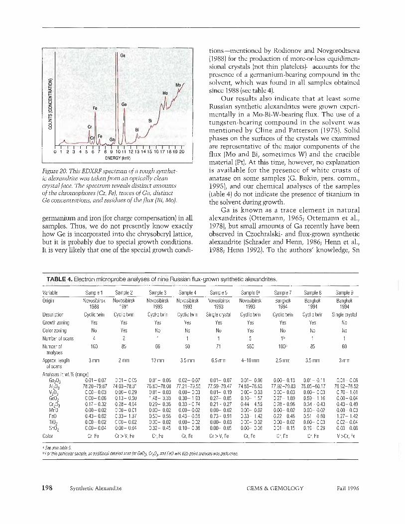
ENERGY (keV)
Figure 20. This EDXRF spectrum of a rough synthet- ic alexandrite was taken from an optically clean crystal face. The spectrum reveals distinct amounts of the chromophores (Cr, Fe), traces of Ga, distinct Ge concentrations, and residues of the flux (Bi, Mo).
germanium and iron (for charge compensation) in all samples. Thus, we do not presently laow exactly how Ge is incorporated into the chrysoberyl lattice, but it is probably due to special growth conditions. It is very likely that one of the special growth condi-
tions-mentioned by Rodionov and Novgorodtseva (1988) for the production of more-or-less equidimen- sional crystals (not thin platelets)-accounts for the presence of a gerrnanium-bearing compound in the solvent, which was found in all samples obtained since 1988 (see table 4).
Our results also indicate that at least some Russian synthetic alexandrites were grown experi- mentally in a Mo-Bi-W-bearing flux. The use of a tungsten-bearing compound in the solvent was mentioned by Cline and Patterson (1975). Solid phases on the surfaces of the crystals we examined are representative of the major components of the flux (Mo and Bi, sometimes W) and the crucible material (Pt). At this time, however, no explanation is available for the presence of white crusts of anatase on some samples (G. Bukin, pers. coinin., 19951, and our chemical analyses of the samples (table 4) do not indicate the presence of titanium in the solvent during growth.
Ga is known as a trace element in natural alexandrites (Ottemann, 1965; Ottemann et al., 19781, but small amounts of Ga recently have been observed in Czochralslzi- and flux-grown synthetic alexandrite (Schrader and Henn, 1986; Henn et al., 1988; Henn 1992). To the authors' knowledge, Sn
TABLE 4. Electron microprobe analyses of nine Russian flux-grown synthetic alexandrites.
Variable Samole 1 Samole 2 Samole 3 Samole 4 Samole 5 Samole 63 Samole 7 Samole 8 Samole 9 Origin Novosibirsk Novosibirsk Novosibirsk Novosibirsk Novosibirsk Novosibirsk Bangkok Bangkok Bangkok
1988 1991 1993 1993 1993 1993 1994 1994 1994 Description Cyclic twin Cyclic twin Cyclic twin Cyclic Iwin Single crystal Cyclic twin Cyclic twin Cyclic twin Single crystal Growth zoning Yes Yes Yes Yes Yes Yes Yes Yes No Color zoning No Yes No No No Yes No No No Number of scans 4 2 1 1 1 5 1 b 1 1 Number of 160
analyses Approx. length 3 mm
of scans Analyses in wt.% (range)
Gaz03 0.01 - 0.07 A1z03 78.20-79.87 V2° 0.00- 0,03 GeO, 0.00- 0.06 crz03 0.17- 0.32 MnO 0.00- 0.02 FeO 0.43- 0.62 TiO, 0.00- 0.02 SnO, 0.00- 0.04
Color Cr, Fe
0,Ol- 0.06 76.80-78.08 0.01 - 0.03 1.48- 3.33 0.29- 0.36 0.00- 0.02 0.50- 0.56 0.00- 0.02 0.32- 0.45
Cr, Fe
0.02- 0.07 77.21 -79.55 0.00- 0.03 0.30- 1.93 0.33- 0.74 0.00- 0.02 0.43- 0.56 0.00- 0.02 0.10- 0.36
Cr, Fe
0.01- 0.06 74.86-78.65 0.00- 0.03 0.10- 1,57 0.44- 4.55 0.00- 0.02 0.33- 1.42 0.00- 0.02 0.00- 0.06
Cr, Fe
0.00- 0.13 77.92-79.83 0.00- 0.03 0.27- 1.89 0.28- 0.96 0.00- 0.02 0.22- 0.46 0.00- 0.02 0.01- 0,15
Cr, Fe
0.01 - 0.1 1 78.05-80.1 7 0.00- 0.03 0.59- 1,16 0.34- 0.43 0.00- 0.02 0.51 - 0.60 0.00- 0.03 0.19- 0.29
Cr, Fe
8 See also table 5. 6 For this particular sample, an additional detailedscan lor GeOa Cr203, and Fed with 625point analyses wasperformed.
198 Synthetic Alexandite GEMS & GEMOLOGY Fall 1996

L.
scan 1
Figure 21. Visible in this color-zoned alexandrite are inner and outer red cores; a narrow, very intense, red boundary; and a light red rim (the yel- low in this photo is a function of the immersion liq- uid and the illuminant). The three electron micro- probe traverses across this section covered growth zones confined to x (scan 1) and a (scans 2 and 3) faces. Viewparallel to the b-axis, immersion, crossed polarizers, magnified 15x.
previously was known as a trace element only in natural alexandrites (Ottemann, 1965; Ottemann et al., 1978; Kuhlmann, 1983). Its presence in some of our samples makes it less useful than before as an indicator of natural origin.
The traces of gallium and tin came from impure chemicals used in the nutrient, and were not inten- tionally added to the solvent system, according to Dr. G. V. Bul& (pers. comin., 1995).
Most of the alexandntes were grown in a nega- tive temperature gradient in contact with the bot- tom of a platinum crucible, as described for berylh- urn-bearing oxides and silicates by Bul& (1993; fig- ure 2C). The exception, the seven small single crys-
Synthetic Alexandite
Figure 22. An electron microprobe traverse across the syntlletic alexandrite shown in figure 21 (scan 2) revealed distinct zoning of the major trace elements- Ge, Cr, and Fe. The inner and outer cores, a narrow boundary, and a rim are recognizable in these plots (no. of analyses: 120; approx. length of scan: 6 mm).
tals that did not show an irregular surface plane, were grown by spontaneous nucleation without contact to the crucible. This is possible in a temper- ature-gradient system in the lower part of the cru-
GEMS & GEMOLOGY Fall 1996

Scan 1: growth zone related to prism x Scan 2: growth zone related lo pinacoid a Scan 3: growth zone related to pinacoid a
GeO, 0.12-0.21 C r A 0.50-0.58 FeO 0.38-0.46
GeO, 0.12-0,18 Cr203 0.46-0.61 FeO 0.37-0.45
GeO, 0.18-0.24 Cr203 0.48-0.58 FeO 0.37-0.41
a For other data on this sample, see table 4, sample 6.
cible (figure 2C), but also in a slow-coolmg system (figure 2A). A vanadium-rich nutrient is likely.
No seed crystal was observed in any of the sin- gle crystals or cyclic twins examined; that is, those crystals with an irregular contact plane and without any broken or sawn parts were grown by sponta- neous nucleation from the solvent mentioned above. It is possible that those crystals that had one broken or sawn surface were produced by seeded growth, but no evidence of this was observed in any of our samples.
The properties of those samples with distinct color zoning indicate a multi-step growth process: First, growth of the core, followed by partial dissolu- tion of the crystal during a period with a higher tem- perature; and then a second growth period, as the temperature was lowered again. The extremely high chromium concentrations found at the beginning of
Figure 23. X-ray fluorescence analysis proved that these white, highly reflecting particles on the sw- face of a rough synthetic alexandrite consisted of platinum, most probably from the crucible. Similar panicles, as well as platinum needles, were seen included in the crystals and faceted synthetic alex -- -{rites. Magnified 50x.
Figure 24. The iqfrared spectra of Russian flux-grown synthetic alexandrites show characteristic absorp- tion bands in the 2800 to 3300 cm-1 range. Sample A was obtained from Novosibirsk in 1993; sample B was acquired in Bangkok in 1994.
the second growth phase in these samples indicate an increase in the Cr concentration of the flux dur- ing the dissolution period.
All samples with this distinct chromium zoning revealed an intense color and a good to very good color change, which is explained by the thin inter- mediate layer of alexandrite with an extremely high chromium content (which could remain, at least partly, after fashioning).
Diagnostic Properties. Faceted Russian flux-grown synthetic alexandrites may show a number of fea- tures that distinguish them from natural alexan- drites.
Careful microscopic examination can detect characteristic forms of residual flux and platinum particles (see also Trossarelli, 1986; Henn et al., 1988; Henn, 1992; Hodglzinson, 1995). Although some patterns of residual flux resemble the healing
200 Synthetic Alexandite GEMS & GEMOLOGY Pall 1996

fractures seen in natural alexandrites (see, e.g., Bank et al., 1987; Henn, 1987; Bank et al., 19881, to date patterns with birefringent components and/or thin films of flux with a net- or web-like structure have been seen only in synthetic alexandntes.
Characteristic growth patterns-which are formed by four dominant crystal faces a, x, k, and o in the Russian synthetic alexandrites-can be observed with immersion microscopy. However, characteristic twin structures and growth patterns in natural gem-quality alexandrites from major locah- ties have not yet been published. Consequently, we do not know how useful these features will be in an identification. Preliminary results indicate that the rhombic prism lz (021), which is seen in most Russian flux-grown synthetic alexandrites, is extremely rare in natural samples (see, e.g., Gold- schmidt, 19 13). Characteristic color zoning-an intensely colored, somewhat rounded boundary between a lighter center and rim-is also diagnostic for some of the Russian samples.
Traces of germanium, molybdenum and/or bis- muth, and sometimes tungsten, provide proof of synthesis. All can be readily determined by X-ray fluorescence analysis. Traces of gallium and tin can be found in natural alexandrites and in synthetic Russian samples, as can the chromophores chromi- um, iron, and sometimes vanadium. Therefore, these trace elements are of no diagnostic value.
Infrared spectroscopy of Russian synthetic flux- grown alexandntes shows some absorption bands in the 2800 to 3300 cm-1 range that are characteristic of this material. Like other synthetic alexandrites, this material lacks the water-related absorption bands that are typical of natural alexandrites.
Gemological properties-such as refractive indices, density, pleochroism, and UV-visible
REFERENCES
Bank F.H., Bank H., Gubelin E., H e m U . (1987) Alexandrite von einem neuen Vorlzommen bei Hematita in Minas Gerais, Brasilien. Zeitschrift der Deutschen Gemmologischen Gesellschaft, Vol. 36, No. 314, pp. 121-131.
Bank H., Gubelin E., Henn U. , Malley J . (1988) Alexandrite: Natural or synthetic? Journal of Gemmology, Vol. 21, No. 4, pp. 215-217.
Bomer W.A., Van Uitert L.G.G. (1968) Growth of divdent metal a l ~ i n a t e s . United States Patent No. 3,370,963; February 27.
Bul& G.V. (1993) Growth of crystals of beryllium oxides and sili- cates using fluxes. Growth of Crystals, Vol. 19, pp. 95-1 10.
Bukin G.V., Eliseev A.V., Matrosov V.N., Solntsev V.P., Kharchenko E.I., Tsvetkov E.G. (1980) The growth and examination of optical properties of gem alexandrite (in Russian). In Inhomogenity of Minerals and Crystal Growth, Proceedings of the XI General
absorption spectra-are of no help in separating Russian flux-grown synthetic alexandrites from their natural counterparts.
CONCLUSIONS The chemical, physical, and microscopic properties of the more than 200 Russian flux-grown synthetic alexandrites we tested are consistent with known details of the production techniques developed in Russia for this material. Platinum crucibles~with a flux containing molybdenum-, bismuth-, and germa- nium-bearing coinponents-are placed in a reverse temperature gradient, in which the growth zone is located below the dissolution zone. Almost equidi- mensional alexandrite crystals grow in this system by spontaneous nucleation in contact with the bot- tom of the crucible. The nutrients-which consist of A1203, BeO, and the chromophores (chromium, iron, and sometimes vanadium oxides)-are placed in the upper parts of the crucibles. The morphology of the crystals, and their chemical and physical properties, are related to the exact compositions of the fluxes and the nutrients, as well as to the temperatures in the upper and lower parts of the crucibles. The man- ufacturers will not reveal the specific growth condi- tions, and the details of these conditions cannot be deduced from study of the synthetic alexandrites that result.
A careful microscopic examination of inclu- sions and structural characteristics (growth patterns and twinning) may be helpful-but is often not con- clusive-in separating natural from synthetic alexandrite. However, modem gemological laborato- ries, especially those with X-ray fluorescence and infrared spectroscopy, should have no problem iden- tifying the synthetic Russian alexandrite material currently available in the trade.
Meeting of the International Mineralogical Association, Novosibirsk, 1978, Moscow, pp. 3 1 7328.
Bulzin G.V., Vollzov S.Yu., Matrosov V.N. , Sevastyanov B.K., Timoshechlzin M.I. (1978) Optical generation in alexandrite (BeAlyOA: C$+) (in Russian). Kvantovaya Elektroivta, Vol. 5, No. 5, pp. 1168-1 169.
Cassedanne J., Roditi M. (1993) The location, geology, mineralogy and gem deposits of alexandrite, cat's-eye and chrysoberyl in Brazil. Journal of Gemmology, Vol. 23, No. 6, pp. 333-354.
Cline C.F., Patterson D.A. (1975) Synthetic crystal and method of making same. United States Patent No. 3,912,521; October 14.
Eliezri I.Z., Kremkow C. (1994) The 1995 ICA World Gemstone Mining Report. ICA Gazette, December 1994, pp. 1, 12-19.
Elwell D., Scheel H J . (1975) Crystal Growth from High- Temperature Solutions. Academic Press, London, New York, an Francisco, 634 pp.
Farrell E.F., Fang J.H. (1964) Flux growth of chrysoberyl and
Synthetic Alexandite GEMS & GEMOLOGY Fall 1996 20 1

alexandrite. Journal of the American Ceramic Society, Vol. 47, NO. 6, pp. 274-276.
Farrell E.F., Fang J.H., Newnham R.E. (1963) Refinement of the chrysoberyl structure. American Mineralogist, Vol. 48, pp. 804-8 10.
Farrell E.F., Newnham R.E. (1965) Crystal-field spectra of chrysoberyl, alexandrite, peridot, and sinhalite. American Mineralogist, Vol. 50, pp. 1972-1981.
Godovikov A.A., Bukin G.V., Vinokurov V.A., Kalinin D.V., Klyakhin V.A., Matrosov V.N., Nenashev B.G., Serbulenko 1M.G. (19821 Development of synthesis techniques for miner- als of economic importance in the USSR (in Russian]. Geol. Geof~~. , Vol. 1982, No. 12, pp. 42-54,
Goldschmidt V. (1900) Zur Theorie der Zwillings- und Viellingsbildung, illustrirt am Chrysoberyll. Zeitschrift fur Krystallograplue und Mineralogie, Vol. 33, pp. 468476.
Goldschimdt V. (1913) Atlas der Krystallformen, Band 11, Calaverit-Cyanchroii. Carl Winters Universitatsbuchhand- lung, Heidelberg.
Goldschmidt V., Preiswerk H. (1900) Chrysoberyllzwilling von Ceylon. Zeitschrift f i i r Krystallographie und Mineralogie, Vol. 33, pp. 455467.
H e m U. (1987) Inclusions in yellow chrysoberyl, natural and syn- thetic alexandrite. Australian Gemmologist, Vol. 16, No. 6, pp. 217-220.
Hem U. (1992) Uber die diagnostischen Merkmale von synthetis- chen Alexandriten aus der Gemeinschaft Unabhangiger Staaten (GUS). Zeitschrift der Deutschen Gemmologischen Gesellschaft, Vol. 41, No. 213, pp. 85-93.
Hem U., Bank H. (1992) Examination of an unusual alexandrite. Australian Gemmologist, Vol. 18, No. 1, pp. 13-15.
Henn U., Malley J., Bank H. (1988) Untersuchung eines synthetis- chen Alexandrits aus der UdSSR. Zeitschiift der Deutschen Gemmologischen Gesellschaft, Vol. 37, No. 314, pp. 85-88.
Hirose T. (1984) Method for washing flux (in Japanese). Japanese Patent Application, Laid-Open No. 5-39796; March 5.
Hodglcinson A. (1995) Alexandrite chrysoberyl surprises. Australian Gemmologist, Vol. 19, No. 1, pp. 25-28.
Isogami M., Nakata R. (1985) Katzenauge aus synthetischem Chrysoberyll-Einlcristall. German Patent Application, Laid- Open No. 3434595, April 18.
Isogami M., Nakata R. (1986) Chrysoberyl cat's-eye synthetic sin- gle crystal. United States Patent No. 4,621,065; November 4.
Kammerling R.C. (1995) Gem trade lab notes: Synthetic alexan- drite flux grown without diagnostic inclusions. Gems &> Gemology, Vol. 31, No. 3, p. 196.
Kammerling R.C., Koivula J.I., Fritsch E., Eds. (1995) Gem News: Sapphires and other gems from Tanzania. Gems o) Gemology, Vol. 31, No. 2, pp. 133-134.
Karfunkel J., Wegner R. (1993) Das Alexandritvorkommen von Esmeraldas de Ferros, Minas Gerais, Brasilien. Zeitschrift der Deutschen Gemmologischen Gesellschaft, Vol. 42, No. 1, pp. 7-15.
Kasuga K. (19841 Synthesizing method of artificial alexandrite sin- gle crystal (in Japanese). Japanese Patent Application, Laid- Open No. 59-107995; June 22.
Kiefert L., Schmetzer K. (1991) The microscopic determination of structural properties for the characterization of optical uniaxi- al natural and synthetic gemstones, part 1: General wnsidera- tions and description of the methods, fournal of Gemmology, Vol. 22, No. 6, pp. 344454.
Kimura S., Kitamura K. (19931 Growth of oxide crystals for opti- cal applications. Journal of the Ceramic Society of Japan, Vol. 101, No. 1, pp. 2247.
Kuhlmann H. (1983) Emissionsspektralanalyse von natiirlichen Rubinen, Sapphiren, Smaragden und Alexandri ten. Zeitschrift der Deutschen Gemmologischen GeseLlschaft, Vol. 32, No. 4, pp. 179-195.
Laslcovenkov A.F., Zhemakov V.I. (1995) An update on the Ural emerald mines. Gems o) Gemmology, Vol. 31, No. 2, pp.
106-1 13. Leung C.S., Merigoux H., Poirot J.P., Zecchini P. (1983) Sur Piden-
tification des pierres fines et de synthfese par spectroscopie infrarouge. Rewe de Gemmologie a.f.g., No. 75, pp. 14-15.
Leung C.S., Merigoux H., Poirot J.P., Zecchini P. (1986) Infrared spectrometry in gemmology. In Morphology and Phase Equilibria of Minerals, Proceedings of the 13th General Meeting of the International Mineralogical Association, Varna 1982, Sofia, Bulgaria, pp. 441448.
Machi& H., Yosliihara Y. [ 1980) Synthetic single crystal for alexan- drite United States patent No. 4,420,834; December 23.
Machida H., Yoshihara Y. I19811 Svnthetischer Einkristall fur einen ~lbxandrit ~de ls teh . ~erm'an Patent Application, Laid- Open No. 2925330; April 2.
Newlay S.K., Pashine J.K. (1993) A note on the finding of rare gemstone alexandrite in Madhya Pradesh. National Seminar on Gemstones, December 11-12, Bhubaneswar, India, pp. 88-90.
News on the Songea deposit from SSEF (1995) ICA Gazette, June, p. 6.
Ottemann J. (1965) Gallium und Zinn im Alexandrit. Neues fahibuch flir Minerfllogie Monatshefte, Vol. 1965, No. 2, pp. 3 1-42.
Ottemann J., Schmetzer K., Bank H. (1978) Neue Daten zur Anreicherung des Elements Gallium in Alexandriten. News fahrbuch fur Mineralogie Monatshefte, Vol. 1978, No. 4, pp. 172-175.
Patnaik B.C., Nayak B.K. (1993) Alexandrite occurrence in Orissa. National Seminar on Gemstones, December 11-12, Bhubane- swar, India, p. 87.
Peretti A,, Schmetzer K., Bernhardt H.-J., Mouawad F. (1995) Rubies from Mong Hsu. Gems a) Gemology, Vol. 31, No. 1, pp. 2-26.
Powell R.C., Xi L., Gang X , Quarles G.J . Walling J.C. (1985) Spectroscopic properties of alexandrite crystals. Physical Review B, Vol. 32, No. 5, pp. 2788-2797.
Proctor K. (1988) Chrysoberyl and alexandrite from the pegmatite districts of Minas Gerais, Brazil. Gems eJ Gemology, Vol. 24, No. 1, pp. 16432.
Rodionov A.Ya., Novgorodtseva N.A. (1988) Crystallization of colored varieties of chrysoberyl by solution-melt and gas transport methods (in Russian). Tr. In-Ta Geol. i G e o f ~ . SO ANSSSR, Vol. 708, pp. 182-187.
Schmetzer I<. (1986) An improved sample holder and its use in the distinction of natural and synthetic ruby as well as natural and synthetic amethyst. Journal of Gemmology, Vol. 20, No. 1, pp. 20-33.
Schmetzer K., Bank H., Gubelin E. (1980) The alexandrite effect in minerals: Chrvsobervl. earnet. corundum, fluorite. Neues Jahrbuch fur ~i&rafo~~e'~bhandlungen, VOI. 138, No. 2, pp. 147-164.
Schrader H.-W., Henn U. (1986) On the problems of using galli- um content as a means of distinction between natural and synthetic gemstones. journal of Gemmology, Vol. 20, No. 2, pp. 108-1 13.
Solntsev V.P., Kharchenko E.J., Matrosov V.N., Bukin G.V. (1977) Distribution of chromium ions in the chrysoberyl structure. Vses. Mineral. Obs. Akad. Nauk SSSR, Trudy IV. Vses. Sympos. Isomorphismu, Part 2, pp. 52-59.
Stoclcton C.M., Kane R.E. (1988) The distinction of natural from synthetic alexandrite by infrared spectroscopy. Gems a)
Gemology, Vol. 24, No. 1, pp. 44-46. Tabata H., Ishii E., Okuda H. (1974) Growth and morphology of
chrysoberyl single crystals. Journal of Crystal Growth, Vol. . . 24/25, pp.656-660. '
Toeawa E. 119851 Method for svnthesizine sinde crystal bv flux -method(in ~a~anese) . ~ a ~ a n & e Patent Application, ~ a i d - ~ ~ e n No. 60-8 1083; May 9.
Trossarelli C. (1986) Synthetic alcxandrite from USSR. La Gemmologia, Vol. 11, No. 4, pp. 6-22.
202 Synthetic Alexandite GEMS & GEMOLOGY Fall 1996

Editor
C. W. Fryer, GIA Gem Trade Laboratory
LAB NOTES Contributing Editors
GIA Gem Trade Laboratory, East Coast G. Robert Crowningshield Karin Hutwit Thomas Moses Ilene Reinilz
GIA Gem Trade Laboratory, West Coast Mary L. Johnson Shane F. McClure
ARAGONITE
A 55.10 x 37.80 x 9.04 mm white translucent carved pendant (figure 1) was recently submitted to the West Coast laboratory for identification. It had been represented to the client as nephrite jade.
The piece was similar in appear- ance to nephrite and had a comparable specific gravity of 2.84. Magnification revealed an aggregate structure. No absorption spectrum was seen with a desk-model spectroscope. The refrac- tive index measurements, which were vague and difficult to determine because of the poor polish, gave val- ues of 1.50 and 1.65. There was a decided "blink" effect when the Polaroid plate was rotated.
Other gemological properties were: moderate yellowish white fluo- rescence to long-wave ultraviolet radiation (with yellow fluorescence in fractures), moderate light yellow fluorescence to short-wave UV, and effervescence when touched in an inconspicuous spot with a minute droplet of a 10% hydrochloric acid solution. Although these properties were not sufficient to identify the material, they proved that it was not nephrite. The effervescence, together with the R.I. "blink" effect, indicated that it was a carbonate, X-ray powder diffraction analysis identified the carving as aragonite.
Aragonite is not often used as a gem material because of its low hard- ness (about 4 on the Mohs scale). A blue massive aragonite from Peru, with gemological properties slightly
204 Gem Trade Lab Notes
Figure 1. This carved pendant resembled nephrite, but advanced testing techniques proved that it was aragonite.
different from those of this specimen, was described in the Winter 1992 Gem News section (pp. 269-270).
SFM and MLf
DIAMOND
Different Colors from the Same Rough Yellow to brown colors in diamond are usually caused by nitrogen impu- rities found in various states of aggre- gation (see "Colour Centres i n Diamonds," by A. T. Collins, Journal of Gemmology, 1982, Vol. 18, No. 1, pp. 37-75). It has been shown that
nitrogen is often distributed uneven- ly in the diamond crystal (see, e.g., "Fractionation of Nitrogen Isotopes in a Synthetic Diamond of Mixed Crystal Habit," by S. R. Boyd et al., Nature, Vol. 33 1, February 18, 1.988, pp. 604-607). Consequently, i t is common that two near-colorless dia- monds cut from the same piece of rough will differ by a few color grades. Hydrogen impurities may also cause an uneven distribution of gray or brown color in diamond (see "Gemmological Properties of Type la Diamonds with an Unusually High Hydrogen Content," by E. Fritsch and I<. Scarratt, lournal o f Gem- mology, Vol. 23, No. 8, 1993, pp. 45 1-460).
Last fall, a diamond dealer shared a particularly vivid example of the consequences of such variability with staff members in the East Coast lab. Although he had noticed some unevenness to the color before saw- ing the rough diamond into the two pieces shown in figure 2, he had expected that the rough would pro- duce two fancy-color stones. However, the larger of the two pieces yielded a 3.79 ct "radiant" cut with a color grade of Fancy Brownish Yellow, whereas the smaller piece finished out as a 0.78 ct pear shape of G color.
Although the two pieces had some similar gemological proper-
Editor's note: The initials at the end of each item identity the contributing editor(s) who provided that item. Gems & Gemology, Vol. 32, No. 3, pp. 204-212 @ 1996 Gemological Institute of America
GEMS & GEMOLOGY Fall 1996

Figure 2. These two pieces are from the same brownish yellow rough diamond. Nearly all the color ended up in the 7,32 ct por- tion, whereas the 1.35 ct piece is near-colorless.
ties-such as inclusions in both of small brown crystals (probably gar- net, judging from their partly dodeca- hedral shape)-there were substantial differences in their infrared spectra, which reflect their different impurity concentrations. The larger, brownish yellow piece had strong peaks due to nitrogen and moderate hydrogen peaks; however, the near-colorless piece showed moderate nitrogen and weak hydrogen absorptions. The nitrogen in both pieces had the same aggregation state, with approximately equal amounts of A and B aggregates. Much of the color in the brownish yellow piece was concentrated in a
swirling cloud in the center, a distri- bution sometimes seen in hydrogen- rich diamonds (again, see the Fritsch and Scarratt reference cited above).
IR Imitation Crystals Since its introduction in the early 1970s, cubic zirconia (or "CZ") has revitalized the diamond simulant market. Its availability in nearly every shape and facet arrangement provides ample evidence of its popularity. We have occasionally reported on CZ being fashioned into carvings and shaped into diamond-like crystal forms. Some of these "crystals" have had very believable diamond-like fea- tures, such as engraved triangular depressions to simulate trigons, engraved parallel lines to simulate growth striations, and "frosted" sur- faces (see Gem Trade Lab Notes, Fall 1982, p. 169, and Winter 1988, p. 241 ).
A good example of this deception was recently seen in the East Coast lab: five fashioned CZ "crystals" (fig- ure 31 that very much resembled modified octahedra, a shape common in rough diamonds. For comparison, we photographed five diamond crys- tals of similar size (see figure 4) to show just how convincing in appear- ance the look-dikes really were. Not onlv was the overall resemblance in shape striking, but one of the imita- tions (at the upper right in figure 3)
even had parallel lines engraved on a "face." These lines closely mimicked the striations often seen on dodecahe- dral faces of rough diamonds with modified octahedral habit (see the upper right stone in figure 41, which are occasionally found on the small natural surfaces sometimes left on polished diamonds.
The ersatz "diamond" rough was submitted to the lab because the obser- vant dealer noted that the "heft" did not feel quite right for diamonds. The specific gravity (5.80 compared to 3.52 for diamond), hardness, and ultraviolet fluorescence of these "crys- tals" were all consistent with pub- lished values for cubic zirconia.
GRC and TM
Natural, with Unseen "Flaws" Rarely is any gemstone examined as carefully for the presence of inclu- sions as is diamond. This is just as true for pieces of rough as for pol- ished stones. A client submitted both partially polished halves of what was originally a 40+ ct crystal to the East Coast lab for examination. The two pieces were worked on a day apart. Both fractured spontaneously (figure 5) in the early stages of cutting.
The highly experienced owner was surprised and puzzled that this had occurred. His rough stones were routinely examined before manufac-
Figure 4. Compare the appearance of these five dia- Figure 3. These five imitation diamond crystals mond crystals, ranging from 5.27 to 8.67 ct, to that of (4.62-26.24 ct) are actually cubic zirconia. the imitations in figure 3.
Gem Trade Lab Notes GEMS & GEMOLOGY Fall 1996

Figure 5. These two diamonds, a 16.48 ct blocked Figure 6. Here the diamonds shown in figure 5 are round and an 18.15 ct blocked square, were cut from oriented and repositioned to demonstrate their the same piece of rough; both fractured due to strain. original crystallogropl11c relationship.
turing, both with a microscope to detect visible inclusions and with a polariscope to detect any extraordi- nary strain or graining. Some diamond categories and colors, such as browns, are noted for their high degree of inter- nal strain. In these diamonds, the pres- ence of strain often influences how the crystal is fashioned. For example, manufacturers will sometimes opt to forgo traditional sawing and keep the stone "whole" to avoid damage. Other times, they may orient the stone so that the sawing does not intersect the center of strain.
We repositioned the two pieces in their original relative orientation to illustrate their relationship in the original piece of rough (figure 6). Figure 7 (taken with a polarizing microscope) shows the blue first- order interference color from residual strain that is present in both pieces. The fractures in both pieces related to a single area of strain that was present in the rough crystal. Also present was a linear strain pattern along the octahedral graining near both culets, but its gray interference colors indicated that this strain was significantly lower.
Whether strain in a rough dia- mond will lead to spontaneous frac- turing during fashioning is a matter of chance, but the presence of local- ized strain is an indication for con- cern. Sawing is thought to be the
Gem Trade Lab Notes
most stressful event in diamond cut- ting; however, in this case the stone survived sawing perpendicular to the strain region, but the pieces fractured as faces were polished subparallel to the strain region. TM and GRC
Rare Color : Fancy Intense Pinkish Orange Over the years, we have reported on a number of diamonds notable for their rare colors (see, for example, the Winter 196546 Gems &> Gemology, p. 362, which illustrated a ring set
Figure 7. First-order interference colors-shades of blue-seen here in the partly polished 18.15 ct piece were actually present in both halves, indicating the pres- ence of residual strain. Magnified 1 Ox.
with natural green, blue, and red dia- monds; Winter 1982, p. 228, which showed a chameleon diamond with a dramatic color change; and Summer 1988, p. 112, with a grayish purple round brilliant cut).
The 3.40 ct heart-shaped dia- mond in figure 8 is another addition to this list. It was graded Fancy Intense Pinkish Orange and Internally Flaw- less. (For a description of the GIA Gem Trade Laboratory color-grading system, see "Color Grading of Colored Diamonds in the GIA Gem Trade Laboratory" by J. King et al., Gems d Gemology, Winter 1994, pp. 220-242.) Not only was the hue unusual for diamond, but the satura- tion was unusually high for such a color: In the rare instances when we have seen diamonds in this hue, the depth of color has been much weaker (less saturated). The rough reportedly came from Angola.
Infrared spectroscopy revealed that the stone was a type Ha diamond (i.e., lacking measurable amounts of nitrogen). The fluorescence was very strong orange to long-wave UV radia- tion and moderate orange to short- wave UV. The long-wave reaction further enhanced the color of the dia- mond when viewed in the daylight. The absorption pattern seen with a desk-model spectroscope consisted of a broad band centered at 550 nm.
TM and IR
Fall 1996 GEMS & GEMOLOGY

A Suite of Treated-Color Pink-to-Purple Diamonds The East Coast laboratory recently had the opportunity to examine six known treated-color pink diamonds borrowed from a local dealer. Although treated pink diamonds are relatively uncommon, we have seen and documented a number of them over the past 25 years. The diagnostic properties noted before (see Gems d Gemology, Summer 1976, p. 172; Summer 1988, p. 112; and Summer 1995, p. 121) were also observed in these diamonds; however this parcel provided a few surprises.
Two of the diamonds showed strikingly unusual colors, which are immediately apparent in figure 9. Although GIA GTL maintains a poli- cy of not issuing color grades for stones of treated color, these stones were put through the color-grading
Figure 8. The Fancy Intense Pinkish Orange color of this 3.40 ct Internally Flawless heart shape is rare.
process in order to locate their posi- tions in color space and to compare them to the range of colors seen in natural-color pink diamonds. Treated pink diamonds are usually highly sat- urated, but dark in tone. The 0.05 carat orangy pink diamond, compara- ble to a grade of Fancy Vivid, was sur- prisingly light in tone for a treated- color pink, as well as being highly saturated. The pink-purple color of the 0.07 carat diamond i s truly extraordinary, comparable to a grade of Fancy Vivid. Purple is an extreme- ly rare color in diamond, and seldom
Gem Trade Lab Notes
Figure 9. Among the colors displayed by this suite of treated diamonds are some that match or exceed the brightest natural pink colors seen in the lab to date. The 0.05 ct orangy pink and the 0.07 ct pink-purple stones, right, are particularly notable for their high saturation.
has the lab seen a purple of this high saturation in either a treated- or natu- ral-color diamond. The orangy pink stone is at least as saturated as any natural-color diamond we have seen of similar hue. T h e colors of the other four diamonds lie on the edges of the distribution we have seen for natural-color diamonds, with the high saturations and medium-to-dark tones that are typical of treated-color pink stones.
In a desk-model spectroscope, all six showed the diagnostic spectrum for treated-color pink (or purple or red) diamonds: sharp absorption lines at 575, 595, and 637 nm. Most of these diamonds showed emission lines a t 595 and 637 nm as well. They also luminesced the character- istic strong, bright orange to both long-wave and short-wave UV that is associated with the 637 n m color center. Last, although graining was present in all six diamonds, i t was phantom graining (for the meaning of this term, see "The Elusive Nature of Graining in Gem Quality Diamonds," by R. E. Kane, Gems d Gemology, Summer 1980, pp. 294-314) with no relationship to the distribution of color within the gems. (By contrast, most natural-color pink diamonds show most, or all, of their color as colored graining.) One stone had a "streaky" color distribution (figure lo ) , but magnification combined with immersion revealed that this color lacked the planar appearance of colored internal graining and was largely confined to the surface.
Although the face-up appearance of both natural- and treated-color pink, purple, or red diamonds can be similar, the causes of the color are entirely different. Natural-color pink diamonds are type la or Da and show a smooth, broad band in the visible spectrum at about 550 nm. (See E. Fritsch and K. Scarratt, "Natural- Color Noncond~ictive Gray-to-Blue Diamonds," Gems d Gemology, Vol. 28, No. 1, Spring 1992, pp. 3839, for a complete discussion of diamond type.) Treated-color pink diamonds must contain at least some type Ib component, and are sometimes pure type Ib. Their visible spectra show the three sharp l ines mentioned
Figure 10. The streaky pink color seen in this 0.05 ct treated-color pink diamond might be confused with the pink graining seen 111
natural-color diamonds. Examination at 1 Ox to while the stone was immersed in methy- lene iodide reveals that the color is largely confined LO the surface.
GEMS & GEMOLOGY Fall 1996

above, with a broad feature formed from the overlap of their sidebands. Vacancies in the atomic structure are created in these diamonds by labora- tow irradiation, and then mobilized during an annealing process. Some of the vacancies become trapped at sin- gle substitutional nitrogen atoms, creating the NV center with its strong absorption at 637 urn.
In examining these six stones, we found that fo& were type Ib, as expected, but one had some addition- al b e IaA component and one of the paler stones had what appeared to be a pure type IaA spectrum and an Hlb peak (due to a vacancy trapped at an A aggregate, a common feature in treated yellow diamonds; again, see the A. T. Collins reference cited in a previous entry). We had not seen such a mid-infrared spectrum in a treated pink stone before. Although the infrared spectrum implied that this diamond had only A aggregates, the visible spectrum showed the 637 nm peak, so there must have been at least some single substitutional nitrogen to trap the vacancies.
The nitrogen content of all six of these diamonds was extremely low, and some of the initial infrared results suggested that a few of them
might have no nitrogen at all. For the stone that showed type IaA, i t is probable that there was not enough single substitutional nitrogen to pro- duce a detectable signal in the infrared spectrum. ~ h e s e diamonds demonstrate the time-honored gemo- logical principle that identification must rely on all of the observed prop- erties. A cursory examination might lead one to conclude that the paler stones are natural-color type Ha pink diamonds with orange fluorescence and faint pink graining. However, in our experience, such stones rarely show the 637 nm line, and never show the 595 nm line, in the hand spectroscope.
John King, Elizabeth Doyle, and IR
In spring 1996, the West Coast lab received for identification a large (25.86 x 18.55 x 13.31 mm) pear- shaped stone that was transparent yellowish green (figure 11). The 38.91 ct stone proved to be an extraordinar- ily large herderite.
We recorded the following gemo- logical properties for this stone: biaxi- a1 negative, with R.I. values of a =
Figure 11. This 38.91 ct faceted herderite is unusually large for this material.
1.580, y = 1.61 1, and between 1.600 and 1.606; S.G. (measured hydrostati- cally) of 3.04; no reaction (inert) to long-wave UV radiation, but faint yellowish green fluorescence to short-wave UV. With a desk-model spectroscope, we observed an absorp- tion line at 585 urn.
Microscovic examination re- vealed a small feather under the table, as well as scattered "pinpoint" inclusions in the stone. However, the most ~ronounced feature seen with magnification was the strong dou- bling of the back facets visible through the table. This was not sur- prising given the strong birefringence (0.031) and the depth of the stone.
To satisfy our curiosity about this stone-and to characterize the material for our data files-we sub- mitted it to energy-dispersive X-ray fluorescence (EDXRF] analysis. Calcium (Ca) and phosphorus [P) were the maior elements found. along with minor manganese and trace amounts of lead, strontium, and yttrium. Gem herderite consists of material in the mineral series that has herderite, CaBe(P04]F, as one end-member and hydroxylherderite, CaBe(P04)OH, as the other. Because the elements beryllium (Be), oxygen (01, fluorine (FJ, and hydrogen (HI cannot be detected with our EDXRF system, we could not determine which end-member in the herderite- hydroxylherderite series is dominant in this stone. The manganese is prob- ably responsible for the yellowish green color, which is similar to the color caused by manganese in some spodumenes. ML/
An intricately carved hairpin (figure 12) with a dragon motif was submitted to the East Coast laboratory to deter- mine if it had been treated. Reportedly, this ornate piece was from the Chinese Qmg dynasty (1644-1912), which pop- ularized the use of jadeite jewelry and objets d'art.
Standard gemological tests re- vealed properties that were consis-
208 Gem Trade Lab Notes GEMS & GEMOLOGY Fall 1996

tent with jadeite jade. The strength of the "chrome" lines in the absorption spectrum varied with the intensity of the green color. There was no reac- tion with a Chelsea filter. Even with magnification, no visible reaction was observed when a "hot point" was brought near the surface. In addi- tion, the carving revealed a compact intergrowth pattern very different from the "honeycomb" structure sometimes seen in bleached and impregnated jadeite. Infrared spec- troscopy showed no evidence of impregnation.
Unlike the simple Western defi- nition of "Imperial jade" (jadeite of uniform intense green color and exceptional translucency], Asian crite- ria are more complex and take into account a combination of factors, including the highest quality green color and translucency, as well as the carving's quality and style (see "Asian News Section: Jadeite Jewellery in the Qing Imperial Court," Christ ie 's International Magazine, 'May 1996, p. 73). We suspect that this hairpin might be considered "Imperial" by either standard.
The difficulty in detecting that a piece of jadeite has been bleached and polymer impregnated, which is now a common practice in the marketplace, has made i t necessary to test all important pieces, regardless of their purported history. GRC and TM
OPAL, an Assemblage
An opaque gray free-form cabochon, displaying primarily green and blue play-of-color, was sent to the East Coast laboratory for identification. Since the stone was bezel set in a closed-back pendant mounting (figure 131, the client wanted us to deter- mine if this opal was a quartz-top doublet or triplet, as is frequently encountered in the trade.
Visual examination showed that the top portion of the cabochon was obviously transparent. The play-of- color was not visible near the surface of the stone, but appeared to be con- fined to a deeper, somewhat opaque
Gem Trade Lab Notes
Figure 12. Reportedly from the Qing dynasty, this 20.3-cm-long jadeite hairpin showed n o evidence of polymer impregnation.
layer. The refractive index of the top, optic character between crossed obtained by the spot method, was polarized plates, but the transparent 1.52, which is lower than the top appeared to be singly refractive 1.54-1.55 of quartz. Because of the with little anomalous double refrac- irregular shape and the bezel mount- tion. When exposed to long-wave UV ing, it was difficult to determine an radiation, the cabochon fluoresced a
GEMS & GEMOLOGY Fall 1996

strong bluish white with a distinct phosphorescence. However, when the stone was exposed to short-wave UV, we noticed a faint chalky yellow fluorescence, which is not character- istic of colorless quartz. These prop- erties proved that the transparent top portion was not quartz, but a differ- ent material.
Magnification did not reveal any obvious inclusions. However, using standard overhead illumination, we did locate a tiny gas bubble deep inside the transparent layer. This confirmed that the top was glass. Further examination of the underly-
Figure 13. This assemblage, which measures about 30 x 22 mm, has a colorless glass top over natural opal.
ing colored layer with strong light showed the usual structure of natural opal. We did not find any evidence of cement planes, so we could not deter- mine if the cabochon was a doublet or triplet without unmounting it. Therefore, we simply identified the piece as an assemblage, with a color- less glass top over natural opal.
IZH
Figure 14. Numerous thread-like "inclusions" were seen in these gray-blue assembled cultured blister pearls, which each mea- swed about 6.35 m m in diameter.
Assembled Cultured Blister PEARLS, With Thread-Like Inclusions
Although gemologists do not expect to observe inclusions when examin- ing pearls, staff members at the West Coast lab noticed some interesting internal features in cultured pearls that arrived last year for identifica- tion. The assembled cultured blister pearls, each of which measured about 6.35 mm in diameter, were an attrac- tive light gray-blue. They were sur- rounded by old European brilliants, all set in a pair of earrings (figure 14).
The fact that these pieces were assembled was readily apparent with microscopic examination. Fiber-optic illumination revealed gas bubbles in the curved interface between the nacre and the half-bead nuclei. The flat bases of the cultured pearls had soft, wax- like backings attached. Not only was the gray-blue color unnatural, but fiber-optic illumination also revealed vivid color concentrations reflecting along hairline fractures in the nacre. Although these features indicated an artificial coloring process, we could not prove that one had been used.
The most interesting characteris- tic of these assembled cultured blister pearls were the thread-like inclusions in the nacre, which were again best observed with fiber-optic illumina- tion. For the most part, these abun- dant inclusions appeared to be ran- domly oriented; they were long, curved, and continuous, with some shorter, more kinked threads splitting
Figure 15. The long curved fibers in the assembled cultured blister pearls of figme 14 seemed, for the most pan, to be zandomly ozient- ed. Magnified 25x.
off to the sides (figure 15). The labora- tory was unable to identify the com- position or origin of these inclusions.
cw
QUARTZ, Single-Crystal Green
Last winter, the East Coast lab had the opportunity to examine a turn-of- the-century ring, stamped "Tiffany &. Co.," set with an oval mixed-cut green quartz that was surrounded by fine-quality old-European brilliant cuts (figure 16). Both the setting and the company name indicated more respect for this gem than is typical today for similar single-crystal quartz of grayish green color. The ring may well represent an example of Tiffany's interest in promoting American gem- stones, as green quartz was known at that time to occur in several locali- ties (see G. F. Kunz, Gems and Precious Stones of North America, 2nd ed., 1968, Dover Publications, New York, pp. 120-122, 263). If so, it joins such American gems as Montana sapphires, chrome pyrope garnets, and American freshwater pearls, among others (see Gem Trade Lab Notes, Spring 1989, p. 37, and The Tiffany Touch by J. Purtell, 1971, Random House, New York).
This color of single-crystal quartz was rare until the mid-1950~~ when it was discovered that amethyst from the Montezuma mine in Minas Gerais, Brazil, would turn green with
Gem Trade Lab Notes GEMS & GEMOLOGY Fall 1996

Figure 16. This tmn-of-the-centu- ry ring from Tiffany features green natural quartz.
heat treatment. Such treated-color quartz is commonly known by the trade name l'prasiolite.'l In recent years, the lab has also seen a few pieces of synthetic quartz with this grayish green color.
The stone in the ring proved to be natural quartz, as it demonstrated both Brazil twinning and parallel color zoning. However, it is not cur- rently possible to distinguish natural- ly green quartz from heat-treated material. GRC and IR
SAPPHIRE, Unusual Treated Natural Sapphire
In the Spring 1996 issue of Gems el Gemology, we reported on flame- fusion synthetic corundum oddities. Earlier this year, within a short peri- od of t ime, the East Coast lab received two rather odd natural sap- phires of treated blue color. The first was a 70.20 ct oval cabochon (figure 17) with an incised design on the back. Microscopic examination revealed numerous fluid-filled "fin- gerprints" and unidentified crystals that were altered in ways consistent with heat treatment. Exposure to long-wave UV radiation produced lit- tle reaction, but the stone fluoresced a patchy chalky blue to short-wave
UV, further supporting the conclu- sion that it had been heat treated.
When examined with mamifica- tion in diffused light, several of the cavities and shallow fractures revealed blue color concentrations reminis- cent of the effect sometimes seen in
from needles to lines of small uncon- nected dots. More importantly, i t also disguised the surface diffusion treatment. Immersion again revealed the telltale outlined facet junctions and uneven surface coloration,
GRC and TM diffusion-treated stones (see, e.g., R. E. Kane et al., "The Identification of Blue Diffusion-Treated Sapphires," Gems el Gemology, Summer 1990, p. 124, figure 10). In this stone, the apparent color "bleeding" was actual- ly a blue "dye," as was evident when the stone was immersed in methy- lene iodide (di-iodomethane; see fig- ure 18). When we re-examined the stone with short-wave UV radiation and low magnification, the areas that luminesced corresponded to those with the blue dye. This treatment could easily have been confused with diffusion treatment because of the shallow penetration of the blue color in some areas.
The second stone (figure 19) was a diffusion-treated natural sapphire that had been quench crackled, k a k - ing it more challenging to identify. Quench crackling, a relatively com- mon procedure, is most often seen in quartz and beryl, which are quench crackled and then dyed green to imi- tate emerald. In the Summer 1996 Lab Notes section (pp. 125-126)) however, we reported on a parcel of quench-crackled synthetic rubies. The crackling in this sapphire made it difficult to see the very small crys- tals and silk, which had been reduced
Figure 17. The. color distribu- tion in this 70.20 ct natmal sapphire suggested some form of tree^-om+
Flame-Fusion SYNTHETIC SAPPHIRE
When GIA was founded in the early 1930s, gemology was relatively uncomplicated and most identifica- t ions could be made with basic instrumentation. However, then as now, the identification of synthetics was particularly worrisome, When we consider the primitive gemologi- cal microscopes available at that time, the great concern for the proper identification of Verneuil flame- fusion synthetics-the only type then available-is understandable.
Pioneering work in Europe had established that the main identifying features in these synthetic sapphires and rubies were curved striae or growth lines, as well as gas bubbles, large or small. One of the first indica- tions that features believed to be characteristic of natural sapphires were also seen in synthetics was reported in 1920 by Mr. E. G. Sand- meier of Locarno, Switzerland, and confirmed by Mr. W. Plato of Frankfurt, Germany: the discovery of polysynthetic twinning in synthetic corundum. It is significant that one of the first gemological notes written
Figure 18. Immersion in meth y- lene. iodide revealed both natural color zoning and evidence of a "dye" in the sapphire .'" ̂ gure 17.
Gem Trade Lab Notes GEMS & GEMOLOGY Fall 1996

Figure 19. This quench-crack- led natural sapphire owes its color to diffusion treatment. Magnified 1 Ox.
by Robert Shipley Jr., in the second issue of the ( then) new Gems o) Gemology-March-April 1934Ñcon cerned his observation of nearly straight striae in a synthetic sapphire. Significant, too, is the fact that the very first (Summer 1942) of many well-illustrated feature articles in this journal by Dr. Eduard Gubelin addressed "Genuine Type Inclusions in New European Synthetic." Occasionally, other similarities between synthetic and natural gems have appeared in the gemological lit- erature. More recently, synthetics
Figure 20. At Hist glance, the needle-like inclusions in this 4.18 ct heart shape seemed to indicate natural origin.
with characteristics introduced to make them look natural, such as nat- ural-appearing "fingerprints" have been seen on the market (see, e.g., J. I. Koivula, "Induced Fingerprints," Gems a) Gemology, Winter 1983, pp. 220-227).
Another example of a natural- appearing inclusion in a synthetic stone was recently seen in the East Coast lab (figure 20). Needle-like inclusions near the cleft of this heart shape had convinced the client that the piece was natural. However, using only a loupe, he thought that
Figure 21. Tha d v e d growth lines easily seen with immer- sion in methylene iodide proved that the sapphire i n fig- we 20 was synthetic.
he also saw curved growth lines. His suspicion proved to be well founded, as the curved growth lines were easi- ly resolved when this synthetic sap- phire was immersed in methylene iodide (figure 21). GRC and TM
PHOTO CREOITS Figures 1 and 14 were taken by Maha DeMaggio, Nicholas DeIRe supplied the pictures lor ligures 2-7, 9, 13, and 16-21. The photo in ligure 8 is compliments 01 Laurence Graff, Shane Ben took figure 10. Shane F. McClure provided figures 1 1 and 15. Figure 12 is com- pliments of Christie's International.
The GIA Learn-At-Home Diamonds Program #41
This two course program will mold you into a true diamond professional via a uniquely struc- tured two-tiered approach. First, you are given the most up-to-date information on diamonds and trained in die art of selling them. Next, you learn the ultimate skill of a jeweler: diamond
p d u . Y6ll'~l Ex able to speak the language other dia- mo& professionals speak. Gain respect as a buyer. I p r n proven techniques for promoting, displaying +rotecting . :...-' diamonds.
Acquire Ac knowledge that is your competitive edge.
Call toll-free (SOQ)421-7250 ext. 292 Outside the U.S. (310) 829-2991 ext. 292 Enroll today!
code Ç GGDP

Spring 1987 "Modern" Jewelry: Retro to Abstract Infrared Spectroscopy in Gem Identification A Study of the General Electric Synthetic Jadeite Iridescent Orthoamphibole Irom Greenland Summer 1987 Gemstone Durability: Design to Display Wessels Mine Sugilite Three Notable Fancy-Color Diamonds The Separation of Natural from Synthetic
Emeralds by Infrared Spectroscopy The Rutilated Topaz Misnomer Fall 1987 An Update on Color in Gems. Part I The Lennix Synthetic Emerald Kyocera Corp. Products that Show Play-01-Color Man-Made Jewelry Malachite Inamori Synthetic Cat's-Eye Alexandrite Winter 1987 The De Beers Gem-Quality Synthetic Diamonds Queen Conch "Pearls' The Seven Types of Yellow Sapphire Summer 1988 The Diamond Deposits of Kalimantan, Borneo An Update on Color in Gems: Part 3 Pastel Pyropes Three-Phase Inclusions in Sapphires from Sri Lank Fall 1988 An Economic Review of Diamonds The Sapphires of Penglai, Hainan Island, China Iridescent Orthoamphibole from Wyoming Detection of Treatment in Two Green Diamonds W n g 1989 The Sinkankas Library The Gujar Killi Emerald Deposit Beryl Gem Nodules from the Bananal Mine 'Opalite:" Plastic Imitation Opal Summer 1989 Filled Diamonds Synthetic Diamond Thin Films Grading the Hope Diamond Diamonds with Color-Zoned Pavilions Fall 1989 Polynesian Black Pearls The Capoeirana Emerald Deposit Brazil-Twinned Synthetic Quartz Thermal ~ l t e r a t i i of Inclusions in Rutilated Topaz Chicken-Blood Stone from China Spring 1990 Gem Localities of the 1980s Gemstone Enhancement and Its Detection Synlhelic Gem Materials in the 1980s New Technologies of the 1980s Jewelry of the 1980s Winter 1990 The O p * o - IdentifU Hr Sapphires A Suite _ ind Jewelry ~meraiaoii~+? Spring 1991 Age, Origin, and Emplacement of Diamonds Emeralds of Panjshir Valley, Afghanistan Summer 1991 Fracture Filling of Emeralds: Opticon and "Oils" Emeralds from the Ural Mountains, USSR Treated Andamooka Matrix Opal Fall 1991 Rubies and Fancy Sapphires from Vietnam New Rubies from Morogoro, Tanzania Bohemian Garnet-Today Winter 1991 Marine Mining of Diamonds off Southern Africa Sunstone Labradorite from the Ponderosa Mine Nontraditional Gemstone Cutting Nontransparent "CZ" from Russia
Spring 1992 Gem-Quality Green Zoisite Kilbourne Hole Peridot Fluid Inclusion Study of Querftaro Opal
, < , , , I , , ' , ,"" . ' ,1 . I'O'!!,:;.~ 'Â¥" I .,'." . ; l i i , ' $ l , ' , , : l l#, l ; I.,,, .',
B , : A C K I S ' S U E S 0 F summer1992 Gem Wealth of Tanzania Gamma-Ray Spectroscopy and Radioactivity Dyed Natural Corundum as a Ruby Imitation
, i t An Update on Sumitomo Synthetic Diamonds ( 16 Fall 1992
'I Ruby and Sapphire Mining in Mogok
I Bleached and Polymer-Impregnated Jadeite Radiation-Induced Yellow-Green in Garnet Winter 1992
itiuniw qBaHBues II1ese ,vssues are suu avauame Determining the Gold Content of Jewelry Metals Diamond Sources and Production
I I Sapphires from Changle, China Spring 1993 Queensland Boulder Opal Update on Diffusion-Treated Corundum:
Red and Other Colors 4 A New Gem Beryl Locality: Luudk i , Finland
De Beers Near Colorless-to-Blue Experimental Gem-Quality Synthetic Diamonds
Summer 1993 Flux-Grown Synthetic Red and Blue Spinels
Emeralds and Green Beryls of Upper Egypt Reactor-Irradiated Green Topaz Fall 1993 Jewels ol the Edwardians A Guide Map to the Gem Deposits of Sri Lanka
1;' Two Treated-Color Synthetic Red Diamonds Two Near-Colorless General Electric Type lla
Synlhelic Diamond Crystals Winter 1993 Russian Gem-Quality Synthetic Yellow Diamonds Heat Treating Rock Creek (Montana) Sapphires Garnets from Allay, China
Emeralds Irom the Mananjary Region,
Synthetic Forsterite and Synthetic Peridot Update on Mining Rubies and Fancy Sapphires in
Northern Vietnam
Meerschaum from Eskisehir Province,Turkey
$ 9.95 ea. U.S. $ 14.00 ea. elsewhere
$125.00 elsewhere $200.00 elsewhere
Some issues from the 1984-1986 volume years are also available. Please contact the Subscriptions Office lor details.
(310) 823-2391, exi. 202 FAX (310) 453-4478 OR WRITE; G&G Subscriptions GIA
1GGD Stewart Street, Santa Monica, CA 90404 USA O R D E R N O W ! Natural-Color Nonconductive Gray-to-Blue Diamonds Peridot as an Interplanetary Gemstone
-

GEM
DIAMONDS Chatham synthetic "white" diamonds at JCK show. Three years ago, Tom Chatham of Chatham Created Gems, San Francisco, California, announced that he would be marketing "white" synthetic diamonds from Russia for jewelry use. Although it took longer than he originally anticipated, Mr. Chatham offered for sale a number of near-colorless synthetic diamond crystals at the June 1996 JCK show in Las Vegas, Nevada.
Mr. Chatham offered GLA Research a brief opportu- nity to examine about 100 of these synthetic diamond crystals (which ranged from about 10 points to almost a carat) before the show. Most were of small size and had too many inclusions for faceting. Research Associate Sam Muhlmeister and Research Gemologist Shane Elen focused their testing on four crystals of slightly better- than-average quality. These weighed between 0.41 and 0.51 ct, and were cubo-octahedral in crystal habit. All four had eye-visible metallic inclusions (figure 11, one had a typical white "cloud," one had relatively large stepped cavities (which resembled the hopper-growth cavities in, for instance, salt crystals, but are unusual in natural diamonds), and two had surface structures that looked like trigons. All four crystals were attracted to a strong magnet.
The crystals were inert to long-wave ultraviolet racli- ation, but fluoresced a very faint yellow or orange to short-wave UV. The UV fluorescence was typical, both in color and intensity, of that seen thus far in near-colorless synthetic diamonds; it is rare for a natural diamond to have a stronger fluorescence to short-wave than long- wave UV. However, no cross-shaped or octagonal pattern was visible in the UV fluorescence reaction-unlike the patterns reported previously for some synthetic diamonds (see, e.g., J. E. Shigley et al., "A Chart for the Separation of Natural and Synthetic Diamonds," Winter 1995, pp. 256-2641, The crystals phosphoresced blue for at least one minute after exposure to short-wave UV; phosphores- cence was much fainter in one than in the other three.
On the basis of their infrared spectra, we determined that these four samples were all type IIa (essentially nitrogen-free) synthetic diamonds. Near-colorless syn- thetic diamonds are typically type Da or mixed type Da
Editors Mary L. Johnson and John I. Koivula
Contributing Editors Dino DeGhionno, Robert C. Kammerling, Shane F, McClure,
GIA GTL, Santa Monica, California Henry A. Hanni, SSEF, Basel, Switzerland Karl Schmetzer, Petershausen, Germany
plus other types, whereas type Da near-colorless natural diamonds are relatively rare.
Energy-dispersive X-ray fluorescence (EDXRF] spec- troscopy disclosed both iron (Fe) and germanium (Gel in all four crystals. GIA Research had not previously detect- ed germanium in any diamond, natural or synthetic. They suspect that Ge is being added to the growth envi- ronment of these crystals to prevent nitrogen from incor- porating into the crystal structure of the synthetic dia- monds, as the nitrogen would color them yellow.
Although all of these properties indicated that these samples were synthetics, conclusive proof was provided most readily by the metallic inclusions, which were eye- visible in all four samples, and were easily identified with magnification. All four proved to be magnetic. The pres- ence of Ge in these samples also provides proof of synthe- sis, but trace-element determination requires the use of equipment beyond the reach of the average gemologist. Mr. Muhlmeister and Mr. Elen cautioned that this prelim- inary study involved only four crystals; the properties of other Chatham synthetic "white" diamonds may differ.
Figure 1. Chatham white" synthetic diamonds were recently offered for sale at the Las Vegas ICK Show. Note the numerous metallic inclu- sions-characteristic of synthetic diamonds-in this 0.51 ct example. Photo by Shane Elen.
214 Gem News GEMS & GEMOLOGY Fall 1996
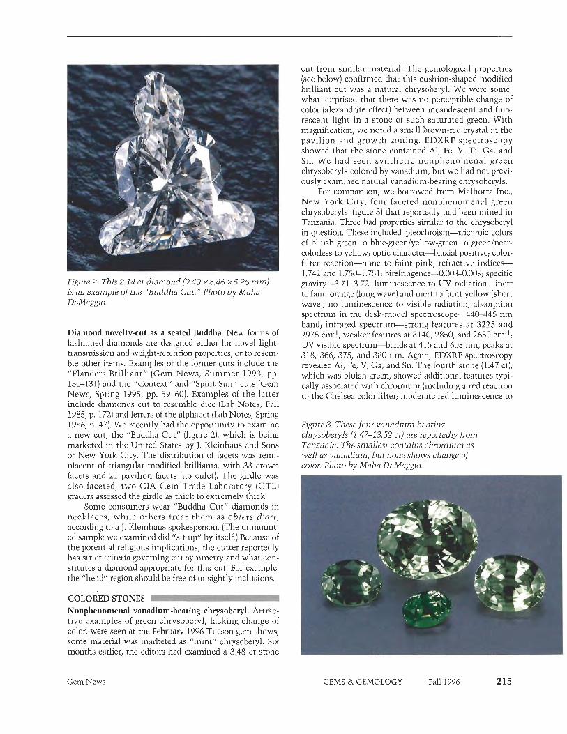
Figure 2. This 2.14 ct diamond (9.40 x 8.46 x 5.26 mm) is an example of the "Buddha Cut." Photo by Maha DeMaggio.
Diamond novelty-cut as a seated Buddha. New forms of fashioned diamonds are designed either for novel light- transmission and weight-retention properties, or to resem- ble other items. Examples of the former cuts include the 'Flanders Brilliant" (Gem News, Summer 1993, pp. 130-131) and the "Context" and "Spirit Sun" cuts (Gem News, Spring 1995, pp. 59-60). Examples of the latter include diamonds cut to resemble dice (Lab Notes, Fall 1985, p. 172) and letters of the alphabet (Lab Notes, Spring 1986, p. 47). We recently had the opportunity to examine a new cut, the "Buddha Cut" (figure 2), which is being marketed in the United States by J. Kleinhaus and Sons of New York City. The distribution of facets was reini- niscent of triangular modified brilliants, with 33 crown facets and 21 pavilion, facets (no culet). The girdle was also faceted; two GIA Gem Trade Laboratory (GTL] graders assessed the girdle as thick to extremely thick.
Some consumers wear "Buddha Cut" diamonds in necklaces, while others treat them as objets d'art, according to a J. Kleinhaus spokesperson. (The unmount- ed sample we examined did "sit up" by itself.] Because of the potential religious implications, the cutter reportedly has strict criteria governing cut symmetry and what con- stitutes a diamond appropriate for this cut. For example, the "head" region should be free of.unsightly inclusions.
COLORED STONES Noiiphenomenal vanadium-bearing chrysoberyl. Attrac- tive examples of green chrysoberyl, lacking change of color, were seen at the February 1996 Tucson gem shows; some material was marketed as "mint" chrysoberyl. Six months earlier, the editors had examined a 3.48 ct stone
Gem News
cut from similar material. The gemological properties (see below) confirmed that this cushion-shaped modified brilliant cut was a natural chrysoberyl. We were soine- what surprised that there was no perceptible change of color (alexandrite effect) between incandescent and fluo- rescent light in a stone of such saturated green. With nlagnification, we noted a small brown-red crystal in the pavilion and growth zoning. EDXRF spectroscopy showed that the stone contained Al, Fe, V, Ti, Ga, and Sn. We had seen synthet ic nonphenomenal green chrysoberyls colored by vanadium, but we had not previ- ously examined natural vanadium-bearing chrysoberyls.
For comparison, we borrowed from Malhotra Inc., New York City, four faceted nonphenomenal green chrysoberyls (figure 3) that reportedly had been mined in Tanzania. Three had properties similar to the chrysoberyl in question. These included: pleochroism-trichroic colors of bluish green to blue-green/yellow-green to greenlnear- colorless to yellow; optic character-biaxial positive; color- filter reaction-none to faint pink; refractive indice* 1.742 and 1.750-1.75 1; birefringenceÑ0.008-0.009 specific gravity-3.713.72; lun~inescence to UV radiation-inert to faint orange (long wave] and inert to faint yellow (short wave); no lun~inescence to visible radiation; absorption spectrum in the desk-model spectroscopeÑ440-44 nm band; infrared spectrum-strong features a t 3225 and 2975 cm-1, weaker features at 3140, 2850, and 2650 cm-1; W-visible spectrum-bands at 415 and 608 nni, peaks at 318, 366, 375, and 380 nm. Again, EDXRF spectroscopy revealed All Fe, V, Ga, and Sn. The fourth stone (1.47 ct), which was bluish green, showed additional features typi- cally associated with chromium (including a red reaction to the Chelsea color filter; moderate red luminescence to
Figure 3. These four vanadium-bearing chrysoberyls (1.47-13.52 ct) are reportedly from Tanzania. The smallest contains chromium as well as vanadium, but none shows change of color. Photo by Maha DeMaggio.
GEMS & GEMOLOGY Fall 1996

Figure 4. Electron microprobe analyses revealed significant differences in chemical content between this natural 11.14 ct bluish green vanadi- um chrysoberyl from the Tunduru area in southern Tanzania and the two synthetic chrysoberyls (right, 1.00 and 1.12 ct) produced in Russia. The natural stone is courtesy of W. Spaltenstein, Bangkok; photo courtesy of SSEF.
visible light; and a 590-665 nm absorption-and 670 nin emission line-seen with the handheld spectroscope, as well as Cr in the EDXRF spectrum); however, there still was no perceptible change-of-color.
Contributing editor Henry A. Hanni had the oppor- tunity to examine an 11.14 ct "intense" bluish green chrysoberyl (figure 4) that was reportedly from Tunduru, Tanzania. An associate at the University of Basel, M. Krzemnicki, performed electron microprobe analyses on this stone and on two samples of Russian hydrothermal synthetic nonphenomenal chrysoberyl that had been pur- chased at Tucson. The natural stone contained 0.4 wt.% V203, 0.2 wt.% F&i03, and trace amounts of Cr, Sn, and Ga; whereas the synthetic chrysoberyls revealed more vanadium (1.8 wt.% ViOaJ1 more chromium (0.2 wt.% Cr203), and no appreciable Fe, Sn, or Ga.
Large faceted chrome diopsides. At one of the 1996 Tucson shows, Alex Grizenko1 of the Russian Colored Stone Company, Genesee, Colorado, showed an editor two dark green oval modified brilliants: chrome diopside from the Inagly mine, Yakutsk, Siberia, north of Lake Baikal. The larger oval, at 26.17 ct, may be the largest known example of this faceted material; however, the 25.33 ct stone (figure 5) was brighter. Although this is not a new find (the rough for these pieces was probably mined 30-40 years ago), this material is increasingly pop- ular in the colored stone market. Mr. Grizenko kindly loaned us these samples for closer examination.
We recorded the following gemological properties for the two chopsides: color-dark green, with even distribu- tion; pleochroism-weak, green to brownish green; diaphaneity-transparent; optic character-biaxial posi- tive; Chelsea filter reaction-none. Refractive indices for the 25.33 ct stone were a = 1.670, (3 = 1.680, and 7 =
1.699, with a birefringence of 0.029; for the 26.17 ct stone, was not determined, but a = 1.672 ,~ = 1.700, and
birefringence was 0.028. Both stones had an S.G. of 3.30, were inert to both short- and long-wave UV radiation, and had very dark spectra as seen with a handheld spec- troscope: The cut-off was at about 520 nm, with "chrome bands" at 630, 660, and 690 nm. Both stones contained scattered small crystals and "fingerprints," vis- ible with magnification but not particularly distinctive. EDXRF spectra of the two stones showed major Mg, Al, and Ca, with smaller amounts of Fe, Cr, Nil Ti, and Sr.
"Rose"-colored plagioclase-corundum rock from Sri Lanka. In March 1995, contributing editor Henry Hanni received two small "rose" pink translucent pebbles (fig- ure 6) that each had one small polished face. These stones reportedly came from a locality near Pallebcdda, Ratnapura district, Sri Lanka. The sender could not iden- tify them on the basis of the R.I. (1.576) and S.G. (2.98) values that he determined. He also noted weak chromi- um lines in the absorption spectrum.
At the SSEF in Basel, microscopic observation of the surface in reflected light revealed a granular groundmass (90%) with occasional interspersed aggregates of idiomor- phic crystals, which ranged from 20 to 70 microns (10%). The pink crystals had a hardness greater than that of the groundmass, as seen by their relatively higher relief. EDXRF analysis of the entire pebble indicated that Si, Al, and Ca were the main constituents, with Cr, Fe, and Sr present as trace elements. On the basis of SEM-EDS anal- ysis of individual mineral grains within the pebbles, the main [groundinass) mineral component was identified as Ca-rich plagioclase feldspar, and the interspersed harder grains were identified as corundum. The Cr was con- tained in the corundum, which explained the rock's pink
Figure 5. The Inagly mine, Yakutsk, Siberia, is the source of this 25.33 ct (22.10 x 15.95 x 9.43 mm) chrome diopside, one of the largest such stones ever seen by the editors. Stone courtesy of the Russian Colored Stone Company; photo by Shane F. McClure.
216 Gem News GEMS & GEMOLOGY Fall 1996

Figure 6. Mixtures of feldspar and corundum, these two pebbles from Sri Lanka have some gem proper- ties common to both materials. The largest pebble is about 1 cm across. Photo courtesy of SSEF.
color and the Cr spectrum. The higher density of the peb- bles-about 2.98, compared to 2.76 for anorthite (plagio- clasel-is also explained by the admixture of corundum.
Dr. H h n i doubts that this material will have great gemstone potential, but he considers it an interesting gemological puzzle: As a mixture of feldspar and corun- dum, it has the R.I. of one, the spectrum of the other, and an S.G. intermediate between the two.
Quartz-magnesite rock, so-called "lemon chrysoprase," from Australia. In past Gem News items, we have report- ed on various yellow-green materials from Australia, including the cryptocrystalline quartz variety chrysoprase (Summer 1994, pp. 125-126; Fall 1994, pp. 193-194), col- ored by nickel, and die nickel-carbonate mineral gaspeite (Summer 1994, pp. 125-126), sometimes marketed as "Allura." Another Australian material was seen through- out the 1996 Tucson gem shows, marketed as "lemon chrysoprase." After a cursory initial inspection, the curiosities of contributing editors Dino DeGhionno and Shane McClure were piqued; they decided to investigate further.
They acquired several samples, including a strand of 7 mm beads and a heart-shaped pendant (figure 7), and selected one 2.27 ct bead for detailed examination. The semi-translucent light yellowish green bead had a specif- ic gravity of 2.83 and refractive indices of 1.51-1.68, with a pronounced carbonate "blink." Fluorescence to both long- and short-wave UV radiation was unevenly dis- tributed-weak yellow in scattered areas. The absorption spectrum viewed with a desk-model spectroscope showed a lower wavelength cutoff at 450 nm; a dark band between 490 and 510 nm; lines at 600, 615, and 630 nmj and an upper-wavelength cutoff at 640 nm. With magnification, distinct areas of a lighter colored, more opaque material and a brighter yellowish green, more translucent material could be seen in the bead; the more
Gem News
opaque material had higher relief (that is, it was harder than the greener material).
EDXRF analysis revealed silicon, magnesium, and nickel. X-ray diffraction powder patterns were consistent with two phases being present: quartz and a carbonate with the calcite structure. The unit-cell spacings deter- mined for the carbonate mineral were consistent with magnesite (MgC03) rather than gaspeite (?C03); howev- er, there is a solid solution between these two minerals, so that a phase can have up to 50% gaspeite and still be con- sidered magnesite mineralogically. One identification question remained: Was the quartz material colored green by nickel (that is, was it chrysoprase?), or was it merely intergrown with the yellow-green carbonate? To answer this, the bead was submerged in a hydrochloric acid solu- tion: The bead was selectively dissolved and turned white; a diffraction pattern showed only quartz. Consequently, we concluded that the "lemon chrysoprase" was not chryso- prase at all, but rather a rock consisting of (white) quartz and (yellowish green) magnesite.
Update on Madagascar sapphires. The Summer 1996 Gems a) Gemology featured an article on sapphires from Madagascar's Andranondambo region (by D. Schwarz et al., pp. 80-99). Since then, we have received additional information about significant discoveries of sapphire elsewhere in this region. Thomas Banker, of Gem Essence Co., Bangkok, Thailand, writes that large quanti- ties of sapphires have also been found at Antsiermene, about 10-12 lzm north of Andranondambo. The "sap- phire rush" at Antsiermene began not long before Mr. Banker's April 1995 visit. Mining resembled that at Andranondambo, with each individual digging accompa- nied by its own small tailings pile of white plagioclase- rich rock. By his second visit in November 1995, a con- siderable shanty town [with about five streets] had devel- oped next to the diggings (figure 8): Mr. Banker estimated
Figure 7. This "lemon chrysoprase " is really a quartz-magnesite rock.. Photo by Maha DeMaggio.
GEMS & GEMOLOGY Fall 1996

that 2,000-3,000 miners inhabited this town at the time of his visit, and others commuted from Andranondambo. The diggings covered about 3-5 km2.
Madagascar is also the source of a large (17.97 kg; 29 x 19 x 16 cm) crystal that was recovered late last year fro111 an
Figure 9. This 89,850 ct blue sapphire crystal, here held by gem dealer Jeffrey Bergman, was found in Madagascar late last year.
218 Gem News
Figure 8. By November 1995, a luge shanty town, with a population in the thousands, had grown up adjacent to the Antsiermene sapphire diggings. Photo courtesy of Thomas Banker.
undisclosed region. The deep blue crystal (figure 9) was the subject of a short report in the June-July 1996 JewelSiam ("The Find of a Lifetime," pp. 86-87].
Spessartine from Pakistan. Late last year, the Gem News editors were loaned samples of spessartine from a relative- ly new locality, Azad Kashmir, in northeastern Pakistani. Dr. Lon C. Ruedisili of Ruedisili Inc., Sylvania, Ohio, pro- vided a 22.31 ct rough crystal and four faceted examples (figure 10) of this garnet, which is being marketed as "Kashmirine." Gemological investigation of the faceted stones revealed: color-slightly yellowish orange to brownish orange or red-orange; diaphaneity-transparent; color distribution-even; optic character-singly refrac- tive, with weak anomalous double refraction; color filter reaction-orange; refractive index-1.800; specific gravi- ty (measured hydrostatically)Ñ4..1 to 4.20; inert to both long- and short-wave UV radiation; and a typical spessar- tine absorption spectrum, with bands at 410, 420, and 430 nin visible with strong transmitted light in a desk- model spectroscope. Using magnification (and for some stones, polarized light), we saw internal growth zoning (figure 11) in all samples. In addition, the 2.31 ct stone contained acicular inclusions, possibly birefringent (fig- ure 12), and the 1.91 ct stone contained two small "fin- gerprint" inclusions. Dr. Ruedisili also provided UV-visi- ble absorption spectra of some of this material-obtained by Dr. Eric Findson of the University of Toledo, Ohio- which showed absorption maxima at 408.5,422,430,461, 482.5,504.5,522.5,563.5, and 611 nm. These gemological properties are similar to those given in a short article on this material by Dr. U. Henn ("Spessartine aus Pakistan," Zeitschrift der Deutschen Gemmologischen Gesellschaft, Vol. 45, No. 2, 1996, pp. 93-94). Dr. Henn reports the composition of one stone (determined by electron micro- probe analysis) as 85.26 mol.% spessartine, 10.13 mol.% almandite, and 4.61 mol.% grossular garnet.
GEMS &. GEMOLOGY Fall 1996

According to Dr. Ruedisili, this material first became known when a 19.30 gram specimen was discov- ered in the summer of 1993. A representative of the Reminy Company, Pakistan (partners with Ruedisili Inc.), saw some of the material at the Mineral and Industrial Development Corporation (MIDC), Azad Kashmir, government auct ion in April 1994. T h e "Kashmirine" garnets are found in a pegmatite in the Janwai-Folawai region (Neelun~ Valley) of Azad Kashinir. The deposit is about 177-200 kin (1 10-124 miles) north- east of Muzaffarabad. Seven pegmatites are being explored for garnets and other gem materials. The main mine is in Jandranwala Nar pegmatite no. 1, which lies about 1,5 km northeast of Folawai Village, at an altitude of 2,590 111. The pegmatite occurs in a migmatite corn- plex, and averages 15 m by 2 m; so far, 143 1113 have been excavated. In addition to the spessartines, quartz and greenish black tourmaline have been found in the gem zone of this pegmatite. These same minerals occur in the neighboring Donga Nar pegmatite, but the spessartine is not of gem quality.
Thirteen kilograms of spessartine were mined in 1994, and 16 kg in 1995. Approximately 20% of this pro- duction was suitable for cutting as cabochons or faceted stones. Most of the fashioned "Kashmirines" seen to date are in the 0.75-7.50 ct range, with a very few stones above 7.5 ct. The largest to date is about 30 ct. A joint venture between Ruedisili Inc., the Reinmy Company, and the Azad Kashmir MIDC is being planned, in order to exploit the spessartines and other gem materials- including morganite, aquamarine, "mint green" and bicolorecl tourn~aline, and topaz-from pegmatites in this region.
Figure 11. Internal growth zoning is visible with transmitted light in this 1.10 ct spessartine garnet from Pakistan. Photomicrograph by John I. Koiviila; magnified 30x.
Figure 10. These four spessartines (0.69-2.31 ct) are from Azad Kashmir, Pakistan. Photo by Maha DeMazgio.
Activity continues at the Capiio do Lana "Imperial" topaz mine. Two mining sites near the historic city of Ouro Preto in Minas Gerais, Brazil, are famous for their production of fine Imperial topaz: Capiio do Lana and Vermelhiio. Current ly , operations a t t h e Vermel- h5o/HCC/Alcan mining complex, on the outskirts of Ouro Preto, are temporarily halted because of a landslide on the boundary between two concessions, according to geologist Daniel Sauer, of Amsterdam Saner, Rio de Janeiro, Brazil. However, the Capiio do Lana mine, in the Rodrigo Silva district, is fully operational.
Figure 12. When examined with polarized light, these needle-shaped inclusions in a 2.31 ct spes- sartine garnet from Pakistan appeared to be bire- frillgent. Photomicrograph by John I. Koiwla; magnified 25x.
Gem News GEMS & GEMOLOGY Fall 1996

Figure 13. Draglines stretch across the large open pit at the Capfio do Lana Imperial topaz mine. Large buckets suspended from the two lines scoop up the gem-bearing slurry from the bottom of the pit and drag it to the top for processing. Photo by Daniel A. Sauer, Amsterdam Sauer, Rio de Janeiro.
During an August 1996 visit to Cap50 do Lana, Mr. Sauer and Gems es) Gemology editor Alice Keller observed the mining operations at what are now two large open pits (approximately 30 m at the deepest point, covering a total area of about 5 ha, or 12 acres) next to one another in the 800-1,000 ha (2,000-2,500 acre) con- cession area. Using draglines (figure 13), bulldozers, and water cannons, miners recover an average of 11,000 m3 of mineralized rocks a month, which are processed to yield about 100 kg of topaz crystals. The estimated yield of fashioned stones from this material is 5.500 ct. , -
Approximately 50 people are currently involved in min- ing and processing the ore.
Typically, the material is heavily included, so totally clean crystals are quite rare. At the mine office, Mr. Sauer and Ms. Keller saw topazes in a wide range of col- o rs~ l igh t yellow, orange-yellow, brownish orange, pink- ish orange ("salmon" or "peach"), pink, reddish orange, orange-red, and purple or violet (figure 14)-all of which
Gem News
Figure 14. Topaz occurs in u wide range of colors at Capiio do Lana, as these groups of natural-color crystals seen at the mine office in R o w o Silva demonstrate (the largest crystal is 180 ct). Red and purple are the rarest colors. Photo by Daniel A. Sauer.
are marketed as Imperial topaz. The most sought-after are the intense pink, red, and purple stones, which- according to mine director Wagner Colombaroli-repre- sent less than one-half of one percent of the total cut- table material. Although these colors occur naturally, many of the pink and red stones on the market today were produced by heat treating the original rough to remove the yellow component.
An article on gem topaz from the Capiio do Lana deposit is in preparation for an upcoming issue of Gems 0) Gemology.
Gem materials from Vietnam. Items on gems from Vietnam regularly appear in Gem News (see, e.g., Winter 1992, pp. 274-275; Summer 1993, p. 134; Fall 1993, pp. 21 1-212; Winter 1993, p. 285; and Fall 1994, p. 197). Vietnamese gems from many provinces were available at the 1996 Tucson shows. Mary Nguyen of Van Sa Inter national, Marina del Rey, California, showed one of the editors (MLJ) several examples of gem rough from Vietnam, including: aquamarine and topaz from Than . Hoa; topaz from the Darlac Plateau; ruby and sapphire rough from Luc Yen; zircon and opal from Pleiku; amethyst and citrine from Phan Thiet; and several mate- rials from Lam Dong, among them tourmaline, peridot, petrified wood, chalcedony, and tektites. This extensive assortment suggests that Vietnam-a region with little previous history or lore in gemology-promises to be a rich source of gem materials for many years to come.
TREATMENTS Coated quartz in "natural" colors. One of the techniques commonly used to change the apparent color of gems is that of coating the sample with a colored material (see, e.g., ll'Tavalite,' cubic zirconia colored by an optical coat- ing," Summer 1996 Gem News, pp. 139-140). The most prominent example of this technology is so-called "aqua-
GEMS & GEMOLOGY Fall 1996

aura" quartz, which owes its blue color to a thin surface coating of gold (Gem News, Winter 1988, p. 251; Fall 1990, pp. 234-2351. At one of the 1996 Tucson shows, mineral dealer Rock Currier of Jewel Tunnel Imports, Baldwin Park, California, showed one of the editors (MLJ) several examples of coated quartz crystals in colors resembling natural quartz varieties. Four samples (figure 15) were borrowed for further study; these resembled amethyst, citrine, green "prasiolite" (heated amethyst), and red "strawberry quartz." The coatings contained gold, bismuth, lead, chromium, titanium, and lesser amounts of calciun~, potassium, and iron, as determined by EDXRF spectroscopy. As with the "aqua-aura" quartz, the coatings on these samples were too thin to affect the 1.54 R.I. value expected for quartz.
SYNTHETICS AND SIMULANTS - Flexible "crystal" fabric. A new product from the Swarovski Company of Wattens, Austria, is a flexible mesh fabric of faceted glass "crystals" (figure 16). The editors recently examined a sample of this "Crystal Mesh," which consisted of 238 mounted foil-backed sin- gle-cuts, each about 2.7-2.8 mm in diameter, which (in our sample) occurred in three colors:
Near-colorless (which had a weak-to-moderate, even light blue fluorescence to long-wave UV radiation,
Figure 16. This 43 x 52 mm flexible swatch of "Crystal Mesh" contains 238 single-cut glass "crystals." Photo by Maha DeMaggio.
Gem News
Figure 15. These four quartz clusters (32.3-68,17 mm long) owe their colors to thin coatings of gold, bismuth, lead, and other elements. Photo by Maha DeMaggio.
and a moderate-to-strong, even whitish yellow fluores- cence to short-wave UV radiation)
Light blue (fluorescing a slightly chalky, weak-to- moderate, even yellow-orange to long-wave UV and a moderate-to-strong, even light blue to short-wave W]
Medium dark blue (fluorescing a weali-to-moder- ate, even blue to long-wave UV and a moderate-to-strong, even blue to short wave UV)
All had the same refractive index, 1.578. When examined with the microscope, these single-cuts were mostly free of inclusions, although some contained scat- tered gas bubbles. Each single-cut was foil-backed and
Figure 17. The single-cuts in the "Crystal Mesh" sample shown in figure 16 are mounted in black cups, which are connected by prongs through black rings; the prongs are cemented closed. View from the back side, magnified 2x. Photomicrograph by John I. IZoimila.
GEMS & GEMOLOGY Fall 1996

Figure 18. Optical fiber glass-like the 2.85 ct cabo- chon (10.03 x 7.86 x4.09 m m ) on the left-is being produced in colors such as this specifically for gem use. A natural (heat-treated) tiger's-eye cabochon (1.83 ct, 9.61 x 7.96 x3.67 m m ) is shown on the right for comparison. Photo by Maha DcMaggio.
fastened with black glue into a black-painted metal cup; these cups alternated with black-painted metal rings, with one of four prongs on each cup folded through the adjacent rings and then glued shut with a brown rubbery material (figure 17). According to product information supplied by the manufacturer, "Crystal Mesh" can be machine-washed but not dry cleaned. Additional colors
Figure 19. A stickpin mounted with a tourmaline attaches this woven 18K gold brooch to the wearer's jacket or dress; other stickpins can be used to change the appearance of the piece. Gold wire-, dia- mond-, and pearl-mounted pins are shown; the brooch is about 5 c m in diameter. Pieces made by Barbara Berk; photo 0 Harold and Erica Van Pelt, Los Angeles.
222 Gem News
and patterns are available, and "Crystal Mesh" is avail- able in pieces as large as 20 x 50 cm (about 8 x20 inches).
Fiber-optic glass imitation of tiger's-eye. Entries on fiber- optic glass (marketed under the names "Catseyte," "Cathaystone," and "Fiber Eye") appeared in die Sun~mer 1991 and Sun~mer 1994 Gem News sections. In the latter section, gray fiber-optic glass was discussed as a simulant of cat's-eye sillimanite from Orissa, India. Fiber-optic glass, which is most often oriented in fashioning to pro- duce an extremely sharp chatoyant band, has been com- mercially available for some time in two colors: white and brown.
During the last few years, we have seen additional colors on the market: saturated yellow, pink, purple, black, and blue, as well as a more subdued llguninetal" grayish blue that yields cabochons reminiscent of hawk's-eye quartz, a bright green similar to some cat's- eye diopside now c o n ~ i n g from India, and a reddish orange similar to some heat-treated tiger's-eye (figure 18). T h e most recent material seen was "striped" in red/white/green, red/blue/green, and red/white/blue. According to a representative of Teton Gems, Boise, Idaho, the white and brown material previously available had been produced and rejected for laser or other techni- cal applications. The newer colors, however, were pro- duced specifically for their gem potential.
Gemological investigation of the 2.85 ct reddish orange glass cabochon shown in figure 18 revealed: 1.55 spot R.I.; 3.09 S.G.; moderate red appearance through die Chelsea filter; weak, dull red fluorescence to long-wave UV and strong, chalky whitish yellow fluorescence to short-wave UV. Magnification revealed that the optic fibers have hexagonal outlines with a "honeycomb-like" structure similar to that seen in other fiber-optic glasses. Also seen, when looking parallel to the fibers, was a "speckled" color appearance, apparently the result of orange fibers intermixed with colorless ones.
Some of the cabochons displayed a sonlewhat less distinct chatoyant band than what has typically been encountered. According to the vendor, these stones had been cut as lower-domed cabochons to give the "eye" a more natural appearance.
MISCELLANEOUS Versatile jewelry. A recurring trend in jewelry design is that of creating pieces in which the stones are inter- changeable, enabling the wearer to adjust color schemes or "looks" with minimum effort. One attractive contem- porary example of this trend is a brooch and stickpin combination (figure 19) designed by Barbara Berk, of Foster City, California. With this set of combination jew- elry, the overall appearance can be easily altered by changing stickpins; in addition to the tourmaline, dia- mond, pearl, and gold wire pins pictured, the set that we saw contained citrine- and onyx-headed stickpins. Virtually any gem material could be adapted for this use.
GEMS & GEMOLOGY Fall 1996

SUSAN B. JOHNSON AND JANA E. MIYAHIRA, EDITORS
THE DEALER'S BOOKS OF GEMS & DIAMONDS By Menahem Sevdermish and Albert Mashiah, 1004 pp., illus,, Kal Printing House, Israel, 1996. US$98.00^
This two-volume work was first pub- lished in Hebrew in 1986 by Mada Avanim Yekarot Ltd.; a second re- vised edition in the same language was issued in 1995. This is the first Enghsh edition.
Menahem Sevdermisli i s a Fellow of the Gemniological Asso- ciation of Great Britain, a founder and president of the Gemological Asso- ciation of Israel, and the owner of a gemstone manufacturing and trading company. He has particular expertise in gemstone cutting and selling. Co- author Albert Mashiah also has impressive credentials: A long-time member of the Israeli urecious stones industry, he has been a vice-president of the Israel Precious Stones and Diamonds Exchange, as well as vice- president of the Israel Emerald Cutters Association and the Gemo- logical Institute for Precious Stones and Diamonds.
This boolz presents an interest- ingly different approach to a gemolog- ical text, in that it is written from the gem dealer's point of view. The authors seem totally at home with tlie business aspects of diamonds and colored stones, as well as with assess- ing rough and cutting it for the niar- ket. In general, however, the two vol- ~uiies of this work differ ill effective- ness aiid value. The chapters on dia- mond are up-to-date and probably the best exposition of current practices in diamond cutting to be found any- where in boolz form. The chapters on diamond grading and on judging value in colored-stone rough are very well
planned and executed. However, the chapters on colored-stone identifica- tion leave something to be desired. Although many of the coniments made from a dealer's viewpoint are germane and useful to the reader, these chapters suggest tliat the authors have had little experience in colored-stone identification in a labo- ratory-or that the copyediting and proofreading were inadequate.
For example, in a discussion of spinel identification, the authors mention that glass would be distin- guished because it is amorphous and, thus, isotropic. As I am sure the authors are aware that both spinel and glass are isotropic, this is undoubtedly a fault of inadequate proofreading. They also state that "it is sometimes very difficult to decide if a stone is peridot or sinhalite, and only a cheini- cal test will distinguish between them." It is true, certainly, that for many years sinhalite was thought to be brown peridot, but the difference in spectra and the nature of die birefrin- gence readily separates the two. In the identification table for the peridot sec- tion, they list the birefringence of sin- halite-which they refer to as DR-as exactly the same as peridot, and they also give tlie refractive indices, sped- ic gravity, and hardness of the two as identical. Both the R.I. and S.G. for sinhalite are higher than those for peridot, and the beta index is closer to that of gamma.
Elsewhere, the explanation of what causes play-of-color in opal leaves the reader bewildered. It states, in referring to the silica spheres, "When the spheres are uneven in size, the light reaching them is dispersed differently in each sphere, so that dif- ferent colors are reflected. But, since the human eye is unable to see the minute spheres, the color con* from
tliis layer will appear white because the human eye interprets a mixture of die spectrum as white." These are just a few of a significant number of exam- ples where careful editing would have been useful. Editing in tlie chapters related to diamond seems to have been niore rigorous.
Yet there are also interesting chapters on subjects not found in other gem books, such as "A Com- mercial Analysis of the Gemstone" and "A Pre-purchase Cost Analysis." Iii addition, there is a lucid account of the ingenious Robogem, a new instru- ment that analyzes rough to obtain maximum yield.
On the whole, the book is useful because it offers not only tlie excep- tionally good diamond chapters, but also unique insights into other areas of tlie gem field. Although slightly flawed, the book seems, to tliis re- viewer, a very worthwhile addition to any gemological library.
RICHARD T. LIDDICOAT Chairman of the Board
Gemological Institute of America Santa Monica, California
NEW FRONTIERS IN DIAMONDS-THE MINING REVOLUTION By David Duval, Timothy Green, and Ross Louthean, 175 pp., illus., piibl. by Rosendale Press, London, 1996. US$55.00*-
History has shown tliat no single fac- tor-other than the world econo- my-has affected tlie orderly func- tioning of the dianiond industry niore
'This book is available for purchase through the GIA Bookstore, 1660 Stewart Street, Santa Monica, CA 90404. Telephone: (800) 421 -7250, ext. 282; outside the U.S. (310) 829-2991, ext. 282. Fax: (310) 449-1 161.
Book Reviews G E M S & GEMOLOGY Fall 1996 223

than the production and availability of rough. Today, exploration for dia- monds is proceeding at a feverish pace on all continents except Ant- arctica. In addition to De Beers, dozens of mining companies have entered the arena ~ h e s e include some of the world's largest, who tra- ditionally have been involved pri- marily with metals. A very few appear to have been eminently suc- cessful, as evidenced by the antici- pated 3 to 5 million carats of produc- tion from one major new mine (BHP/Dia Met) in Canada by the end of this century.
Responding to the interest that all of this activity has generated, three prominent resource j6urnalists-from three widely separated parts of the world-have teamed up to review the higlillghts of diamond exploration dur- ing the last decade. The result is this small book, which is divided into four parts. Information is remarkably cur- rent, as the Febmiry 1996 "agreement" between De Beers and Russia is men- tioned several times.
Part 1 (Green, London], "The Global View," reviews the special and essential role of De Beers in the dia- mond industry. It then proceeds to summarize the history and current status of mining and production. The main focus is on Africa (which is still the world's most important diamond producer, with-according to 1994 data-46% by weight and 69% by value of world uroductionl. There are many interestkg statistics and facts; for example, a ship looking for marine diamonds off Namibia can "mine" 0.25-0.40 km2 of ocean bottom uer year. However, there are also occa- sional errors-such as the area of the Mwadui mine (Tanzania) given as 13 km2, when its surface area is actually 146 hectares, or 1.46 km2. The chap- ter concludes with a discussion of production from Russia, followed by brief comments on exploration in Finland, Brazil, and India.
Part 2 (Duval, Vancouver), "Can- ada: Joining the Big League," is a nar- rative-style review of the history of diamond exploration in the North- west Territories, which led to the dis- covery of the Lac de Gras kimberlite
field by Charles Fipke in 1991. From Duval's discussion of the current exploration activity by about a dozen companies (most small and specula- tive), it is clear that only the BHP/ Dia Met mine mentioned above approaches commercial viability at this time. The difficulties of explor- ing for diamonds-especially the heavy investments in time and money required-become evident in this chapter and the next.
Part 3 (Louthean, Perth), "Aus- tralia: Any Heirs to Argyle?," is simi- lar in scope to Part 2, except that it places heavy emphasis on the Argyle mine (its discovery, development, corporate structure, marketing strate- gies, and the crucial question of whether it will be able to operate after about 2003). Also discussed are many of the companies presently exploring in Western Australia, New South Wales, and offshore, where rivers draining the Argyle region empty into the sea. Brief mention is also made of exploration in Kalimantan, on the island of Borneo. However, the ques- tion as to who (if anyone) will be Argyle's heir is not answered.
Part 4 (Green, London), "Who Will Buy My Beautiful Diamonds?," is a short, statistics-based discussion of the world retail trade (there is a seemingly relentless rise in diamond jewelry sales). Green concludes that the markets for diamonds in the United States and Japan have matured. Future additional production will be consumed in East Asia (Taiwan, South Korea, Thailand, eventually China, and-it is hoped-India).
It must be noted that every major topic in this book (including most of the figures and all three tables) can be found in articles that have appeared recently in such sources as JCK, Diamond Inter- national, Northern Miner, literature available from two investment (secu- rities) companies, and this journal (Gems o) GemologyJ. Those gemolo- gists and jewelers who have kept abreast of the professional literature will have a sense of deja vu when they read this fairly expensive review. Nevertheless, this conveniently sized compendium will be appreciated by
those who are just entering the field or have not kept up with recent events.
ALFRED A. LEVINSON, PH.D. University of Calgary
Calgary, Alberta, Canada
PHOTOGRAPHING MINERALS, FOSSILS AND LAPIDARY MATERIALS By Jeffrey A. Scovil, 224 pp., illus., Geoscience Press, Tucson, AZ, 1996, USS40.00*
This important "how-to" book will be useful to anyone-beginner or pro- fessional-who wants to improve their photography of gems and min- erals. It explains in plain language, for those not trained in this type of pho- tography, the equipment and proce- dures necessary. Line illustrations and photographic examples clearly illustrate these lessons.
Specifically, the book describes techniques for cameras that use a film size from 35 mm up to 4 x 5 inches. This includes selection of lenses, films, lighting, filters, and backgrounds. Also explained and illustrated are special approaches to magnification in photomicrography, macro images, stereo views, and pho- tographing fluorescence.
Authors who intend to travel to mines or other locations can improve the quality of their photos by follow- ing Mr. Scovil's guidelines. They can also learn important tips on packing photo equipment for various modes of transportation, as well as how to prevent equipment loss or theft dur- ing international travel.
Of help to lecturers are the tech- niques Mr. Scovil gives for presenting slide shows and his advice on how to copy artwork and line drawings. Writers can also improve their pre- sentations by using the reproduction procedures and instructions available in this valuable book.
Overall, this publication is a use- ful addition to the library of amateur and professional photographers ahke.
HAROLD VAN PELT Van Pelt Photography
Los Angeles, California
224 Book Reviews GEMS & GEMOLOGY Fall 1996

REVIEW BOARD Emmanuel Fritsch Marv L. Johnson Himiko Naka University of Nantes, France G I A G ~ ~ Trade Lab, Santa Monica Pacific Palisades, California
Charles E, Ashbaugh Ill Isotope Products Laboratories A. A. Levinson Gary A. Roskin Michael Gray Burbank, California University 01 Calgary European Gemological Laboratory Missoula, Montana Calgary, Alberta, Canada Los Angeles, California Andrew Christie GIA, Santa Monica Patricia A, S, Gray
Missoula, Montana Loretta B, Loeb Visalia, California
James E. Shigley GIA, Santa Monica
Jo Ellen Cole Carol M. Stockton Elise B. Misiorowski
GIA, Santa Monica Professor R. A. Howie Alexandria, Virginia Royal Holloway
GIA, Santa Monica Rolf Tatje
Maha DeMaggio University of London Jana E. Miyahira Duisburg University GIA Gem Trade Lab, Santa Monica United Kingdom GIA, Santa Monica Duisburg, Germany
COLORED STONES AND ORGANIC MATERIALS Cretaceous mushrooms in amber. D. S. Hibbett, D.
Grimaldi, and M. J. Donaghue, Nature, October 12, 1995, p. 487.
Recently, two mushrooms were discovered in amber of Turonian age (90-94 million years old, mid-Cretaceous] in central New Jersey. One specimen is nearly complete, with an intact cap, distinct gills, and a central stalk (it is the old- est known such mushroom, by about 60 d o n years); the other is a wedge-shaped fragment of a mushroom cap. Both mushrooms resemble modern common leaf-litter and wood-decayer species, and both were growing on a cedar (a member of the Cupressaceae family). ML/
Opal. extrdapis, No. 10, 1996, 96 pp. [In German]. Opal is the subject of another extraLapis, an issue of Lapis magazine that is devoted entirely to one gemstone. Following a comprehensive introduction by Edward Giibelin, a series of articles provide information on all important aspects of t h s colorful gem.
An article by Max Weibel explains the origin of play- of-color. Two other papers describe Queensland's boulder opals, their forms, production, and prospecting methods (Wilson Cooper and Barry J. Neville); and the geologic set- ting and processes that led to opal formation in the sedi- ments of Australia's Great Artesian Basin (Jack
Townsendl. In disagreement with traditional theories of - opal formation, Len Cram offers a surprising new model, based on ion exchange, that he demonstrated by growing synthetic opal out of "opal dirt" in a bottle in just three months. Jiirgen Schutz describes the long history of Mexican opals, their varieties, and the present mining sit- uation. Jochen Knigge recounts the history and produc- tion of opals from Pedro 11, Piaui, Brazil. Klaus Eberhard Wild portrays another important locality-Kirschweiler, near Idar-Oberstein-which was (and perhaps still is] one of the most important centers of opal fashioning and trade worldwide.
Jiirgen Schiitz explains the factors that determine the price of an opal (locality of origin, body color, play-of-color,
This section is designed to provide as complete a record as prac- tical of the recent literature on gems and gemology Articles are selected for abstracting solely at the discretion of the section edi- tor and his reviewers, and space limitations may require that we include only those articles that we feel will be of greatest interest to our readership.
Inquiries for reprints of articles abstracted must be addressed to the author or publisher of the original material. The reviewer of each article is identified by his or her initials at the end of each abstract. Guest reviewers are identified by their full names. Opinions expressed in an abstract belong to the abstrac- ter and in no way reflect the position of Gems & Gemology or GIA. 0 7996 Gemological Institute of America
Gemological Abstracts GEMS & GEMOLOGY Fall 1996 225

pattern, cut, size). Even with these criteria, it remains dif- ficult to know how much a harlequin opal is really worth. Three additional articles provide information on opal nomenclature (Jurgen Schutz and Manfred Szykora); dou- blets, triplets, and opal mosaics (Karl Fischer]; and synthet- ic opals and opal simulants (Manfred Szylzora]. The volume concludes with a description of opalized fossils: snails, mussels, belemnites, and even dinosaurs [Alex Ritchie and Brigitte Szylzora).
This extraLapis also contains short descriptions of smaller opal sources [Denmark, Honduras, Indonesia, Mali, Saxony, Slovakia [formerly Hungary], Turkey, and the United States]; an opal glossary; and the stories of the Hope and El h i l a Azteca opals (by John S. White). Also described is an extraordinary opal necklace that Queen Elizabeth I1 was not given as a coronation present (by Helmut Weis]. Two stories tell us how Australian aborig- ines explain the origin of opals.
A volume about opals with words only (in this case, German) would be utterly frustrating. In this edition, however, the stunning beauty and incredible variability of opals is illustrated throughout the entire volume by wonderful color photographs. RT
Zur Entstehung der sternfoermigen Achate in sauren Vulkaniten. Eine modifizierte Bildungstheorie (The origin of star-shaped agates in acidic vulcanites. A modified theory of formation). R, Rykart, Der Aufschluss, Vol. 46, 1995, pp. 33-36.
It has generally been believed that agate formation in rhy- elites and porphyries takes place at high temperatures. Recent research by M. Landmesser has shown that agate may form in other types of rocks at lower temperatures. In this article, Mr. Rylzart proposes a new theory for the for- mation of star-shaped agates in lithophysae (e.g., thunder eggs] in rhyolitic vulcanites. The basic idea is that the gaseous bubbles in the magma contract to form polygonal cavities because of dropping gas pressure during cooling near the Earth's surface. Subsequently, monomer H4Si04, dissolved in the water that invades the cavities, fills them with chalcedony and quartz. The surrounding rhyolite devitrifies and hardens, forming the well-known quartz porphyry kills. R T
DIAMONDS Aber Resources Ltd. Diamond Industry Week, February
26, 1996, p. 3. Aber Resources has announced results from drill cores at A-418, one of their lumberlite pipes in the Northwest Territories, Canada. Nineteen tons of ore in a large-diain- eter (6 inches, about 15 cm] core drilled through 367 m of lumberlite yielded 83.1 carats of diamonds-4.3 carats per ton of ore-with individual stones between 0.025 and 3 carats. The largest "gem" diamond weighed 2.2 carats. The A-418 pipe is estimated to contain 15 million tons of ore to 650 in depth; the grade is similar to that of the A- 154 South lzin~berlite, which showed 4.5 carats per ton of
ore, at a valuation of $58.17 per carat. Bulk sampling is proceeding at the A-154 South, A-154 North, and A-21 lzimberlites. MLf
Diamonds everywhere. C. Koeberl, Nature, November 2, 1995, pp. 17-18.
On Earth, diamonds usually occur in rocks derived from the mantle. They are thought to have formed from fluids or melts in the upper mantle at "immense" temperatures and pressures, probably-according to Mr. Koebcrl-dur- ing several diamond-forming events early in the Earth's history. Diamonds have also been produced, directly on the Earth's surface, during meteorite impacts; such dia- monds may have formed, at least in one case [Ries Crater), from the vapor phase. Diamonds found in iron meteorites and ureilites [another variety of meteorite) were formed by shock from graphite or an~orphous car- bon, probably in the meteorite and not after it arrived on the Earth. Nanometer-size diamonds have been found in chondritic meteorites, associated with noble gases [xenon, argon, etc.] with unusual isotopic compositionsj these came from interstellar or presolar events very early in the history of the solar system. Small diamonds have also been found in clays marking the boundary of the Cretaceous and Tertiary periods, which has evidence of a large impact; their carbon and nitrogen isotopes point to an origin within the impact event or the resulting fireball. Polycrystalline diamonds up to 1 cm, discovered in impactites at a few Russian and Ukrainian impact stnrc- tures, also appear to be crustal in origin. Impact-produced diamonds are very different from microdiamonds found in high-grade inctamorphic rocks.
Also rare and unusual are polycrystalline black dia- monds, called carbonados. No carbonado diamond has ever been found in situ in a rock. Possible origins include carbon subduction in the mantle, shock metamorphism during impact, or irradiation of organic matter; vapor- deposition may also be a candidate. MLJ
Diamonds: Wyoming's best friend. Geotimes, Vol. 41, No. 2, February 1996, pp. 9-10.
The first diamond mine in Wyoming is about to begin pro- duction, and many more lumberlites and lamproites in the region may contain diamonds, according to W. Dan Hausel of the Wyoming State Geological Survey. Redaurum Red Lake has just finished construction of a 140-ton-per-hour ore-processing ~ L U for the cornpanyls Kelsey Lalze di'mond property, along the Colorado-Wyoming state line; several gem diamonds, up to 14.2 ct, already have been recovered from this property. The Colorado-Wyoming lumberlite province includes more than 100 lumberlite intrusives, one of the world's largest lamproite fields, and dozens of unex- plored geophysical and geochemical anomalies. More than 120,000 diamonds have been recovered from this area in the last 20 years.
No history of diamond mining in Wyoming is con~plete without mention of the "Great Diamond Hoax of 1872." A
226 Gemological Abstracts GEMS & GEMOLOGY Fall 1996
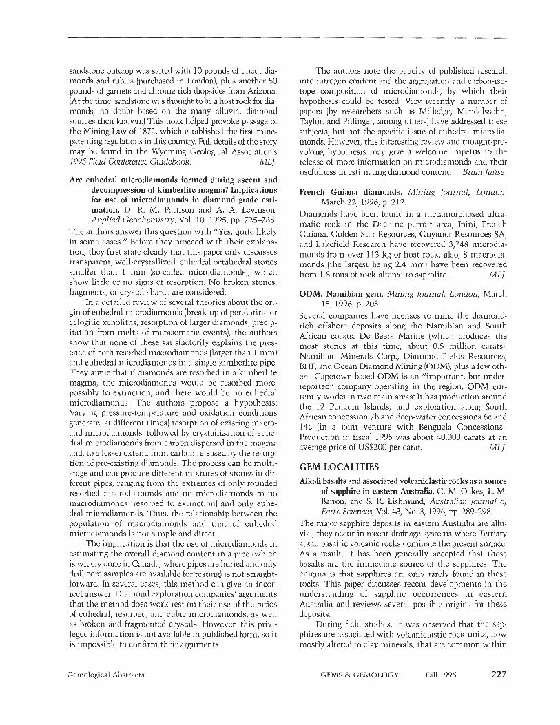
sandstone outcrop was salted with 10 pounds of uncut dia- monds and rubies (purchased in London), plus another 50 pounds of garnets and chrome-rich diopsides from Arizona. (At the time, sandstone was thought to be a host rock for dia- monds, no doubt based on the many alluvial diamond sources then known.) This hoax helped provoke passage of the Mining Law of 1872, which established the first niine- patenting regulations in this country. Full details of the story may be found in the Wyoming Geological Association's 1995 Field Conference Guidebook. MLJ
Are euhedral microdiamonds formed during ascent and decompression of kimberlite magma? Implications for use of microdiamonds in diamond grade esti- mation. D. R. M. Pattison and A. A. Levinson, Applied Geochemistry, Vol. 10, 1995, pp. 725-738.
The authors answer this question with "Yes, quite likely in some cases." Before they proceed with their explana- tion, they first state clearly that this paper only discusses transparent, well-crystallized, euhedral octahedral stones smaller than 1 mm (so-called microdiamoncls), which show little or no signs of resorption. No broken stones, fragments, or crystal shards are considered.
In a detailed review of several theories about the ori- gin of euhedral microdiamonds (break-up of peridotitic or eclogitic xenoliths, resorption of larger diamonds, precip- itation from melts of inetasomatic events), the authors show that none of these satisfactorily explains the pres- ence of both resorbed macrodiamonds (larger than 1 mm) and euhedral microdiamonds in a single lumberlite pipe. They argue that if diamonds are resorbed in a lzimberlite magma, the microdiamonds would be resorbed more, possibly to extinction, and there would be no euhedral microdian~onds. The authors propose a hypothesis: Varying pressure-temperature and oxidation conditions generate (at different times) resorption of existing macro- and microdian~onds, followed by crystallization of euhe- dral microdiamonds from carbon dispersed in the magma and, to a lesser extent, from carbon released by the resorp- tion of pre-existing diamonds. The process can be multi- stage and can produce different mixtures of stones in dif- ferent pipes, ranging from the extremes of only rounded resorbed n~acrodiamonds and no n~icrodiamonds to no macrodiamonds (resorbed to extinction) and only euhe- dral microdiamonds. Thus, the relationship between the population of n~acrodiamonds and that of euhedral microdicimonds is not simple and direct.
The implication is that the use of microdian~onds in estimating the overall diamond content in a pipe (which is widely done in Canada, where pipes are buried and only drill core samples are available fortesting) is not straight- forward. In several cases, this method can give an incor- rect answer. Diamond exploration companies' arguments that the method does work rest on their use of the ratios of euhedral, resorbed, and cubic microdiamonds, as well as broken and fragmented crystals. However, this privi- leged information is not available in published form, so it is impossible to confirm their arguments.
The authors note the paucity of published research into nitrogen content and the aggregation and carbon-iso- tope composition of microdiamonds, by which their hypothesis could be tested. Very recently, a number of papers (by researchers such as Milledge, Mendelssohn, Taylor, and Pillinger, among others) have addressed these subjects, but not the specific issue of euhedral rnicrodia- monds. However, this interesting review and thought-pro- voicing hypothesis may give a welcome impetus to the release of more information on microdiamonds and their usefulness in estimating diamond content. Bram Janse
French Guiana diamonds. Mining Journal, London, March 22, 1996, p. 212.
Diamonds have been found in a metamorphosed ultra- mafic rock in the Dachine permit area, Inini, French Guiana. Golden Star Resources, Guyanor Resources SA, and Lakefield Research have recovered 3,748 microdia- monds from over 113 kg of host rock; also, 8 macrodia- monds (the largest being 2.4 mm) have been recovered from 1.8 tons of rock altered to saprolite. ML1
ODM: Namibian gem. Mining Journal, London, March 15, 1996, p. 205.
Several companies have licenses to mine the diamond- rich offshore deposits along the Namibian and South African coasts: De Beers Marine (which produces the most stones at this time, about 0.5 million carats), Namibian Minerals Corp., Diamond Fields Resources, BHP, and Ocean Diamond Mining [ODM), plus a few oth- ers. Capetown-based ODM is an "important, but under- reported" company operating in the region. ODM cur- rently works in two main areas: It has production around the 12 Penguin Islands, and exploration along South African concession 7b and deep-water concessions 6c and 14c (in a joint venture with Benguela Concessions). Production in fiscal 1995 was about 40,000 carats at an average price of US$200 per carat. ML1
GEM LOCALITIES Alkali basalts and associated volcaniclastic rocks as a source
of sapphire in eastern Australia. G. M. Oakes, L. M. Ban-on, and S. R. Lishrn~md, Australian Journal of Earth Sciences, Vol. 43, No. 3, 1996, pp. 289-298.
The major sapphire deposits in eastern Australia are allu- vial; they occur in recent drainage systems where Tertiary alkali basaltic volcanic rocks dominate the present surface. As a result, it has been generally accepted that these basalts are the immediate source of the sapphires. The enigma is that sapphires are only rarely found in these rocks. This paper discusses recent developments in the understanding of sapphire occurrences in eastern Australia and reviews several possible origins for these deposits.
During field studies, it was observed that the sap- phires are associated with volcaniclastic rock units, now mostly altered to clay minerals, that are common within
Gemological Abstracts GEMS & GEMOLOGY Fall 1996 227

the main basaltic sequences. [Volcaniclas~ic means a rock composed of volcanic fragments, and includes such rock types as ash, tuff, or breccia). The volcaniclastic units are laterally extensive, but they are thin, easily eroded, and generally poorly exposed. In some locations, however, extraordinary concentrations of sapphires (up to 12 kg per cubic meter) have been observed within these units. These volcaniclastic roclzs are the products of the early explosive stages of the basaltic volcanic episodes of eastern Australia, and they are chemically distinct (i.e., "more fractionated") from the surface basalts that are products of quieter episodes.
The Tertiary volcaniclastic rock units constitute prime exploration targets for alluvial sapphires (and asso- ciated minerals such as zircon and spinel) in eastern Australia and possibly in similar geologic provinces else- where (e.g., Southeast Asia). AA L
Alkaline rocks and gemstones, Australia: A review and synthesis. F. L. Sutherland, Australian Journal of Earth Sciences, Vol. 43, No. 3, 1996, pp. 323-343.
Valuable gemstones that occur in Australian alkaline roclzs include diamonds in lamproites and lumberlites; sapphires, zircons, and rubies in alkali basalts; and one gem zircon prospect in carbonatite. This paper reviews the tectonic settings and origins of Australia's gem-bear- ing alkaline roclzs.
There are marked contrasts between diamond and sapphire-zircon associations across the continent. Most western cratonic areas exhibit episodic, sparse, deep allza- line activity from the diamond zone (2 billion-20 million years [My] old). However, in eastern fold-belt areas, pro- lific Mesozoic/Cenozoic basaltic volcanism carried up considerable amounts of sapphire and zircon (since 170 My). Some South Australian Mesozoic lumberlitic dia- mond events (180-170 My) represent ultra-deep material rising through the mantle transition zone. Eastern Australian diamonds are unusual; at present, their origin is in dispute. Several different models compete to explain sapphire/zircon formation in eastern Australia. These range from eruptive plucking of metamorphosed sub- ducted materials to crystallization from felsic melts to carbonatitic reactions. Pb-U isotopic zircon ages favor for- mation during Phanerozoic basaltic activity and not d ~ u - ing earlier Paleozoic subduction or granitic-intrusion events. A problem for the theory that zircon crystallized from fractionated basaltic melts is negligible Eu depletion in rare-earth-element patterns.
The authors propose a model that favors sapphire/ zircon crystallization from relatively small-volume, lit- tle-evolved, felsic melts that are generated from metaso- matized mantle as the lithosphere overruns subdued hot spot systems, initiated at Tasman-Coral Sea margins. A unique ruby, sapphire, sapphirine, spinel assemblage from the Barrington basalt shield in New South Wales marks a separate ruby/pastel-colored-sapphire genesis.
RA H
Country summaries. African Mining Supplement to Mining Journal, London, January 26, 1996, pp. 7, 9, 13, 15, 17, 19, 21, 23.
This article summarizes mining activities, by country, for African nations in 1994. Reports relevant to gemstones- primarily diamonds-include those for:
Angola, where only state-owned Endiama, or its joint ventures, can hold diamond-mining rights. Alluvial mining totaled 1.25 million carats (Mct) in 1992, but offi- cial production has collapsed since.
Botswana, the second biggest producer of gem dia- monds after Russia. Recovery from Jwaneng, Orapa, and Letlhalzane rose 6%) to 15.5 Mct in 1994. The value of diamond exports rose 1 %, to US$1.4 billion.
The Central African Republic, with official produc- tion figures of 530,000 carats annually.
Congo, where traces of diamonds were found near the border with the Central African Republic and on the island of M'bainu, near Brazzaville.
Ivory Coast, where two diamond mines, at Tortiya and Skguela, produce about 15,000 carats annually.
Ghana, which produced about 750,000 carats of diamonds in 1994.
Guinea; production at Aredor's diamond mine at Banankoro was suspended in 1994.
Liberia, where illicit gold- and diamond-mining activity continued around the Lofa River, on the border with Sierra Leone.
Malawi, which continues to have "extremely lirnit- ed" production.
Mali; 20 kimberlite pipes have been found in the southwest, but no production has begun.
Namibia, a major diamond producer (over one-third of its export income comes from diamonds). Production from onshore and offshore deposits rose 15% in 1994, to 1.31 Mct (95% of which was gem quality), mostly from Namdeb (or its predecessor Consolidated Diamond Mines).
Sierra Leone; diamond production from the eastern Kono region generated 255,000 carats of exported dia- monds, valued at US$30.2 million. Civil unrest disrupted mining in most other areas.
South Africa, which produced 10.8 Mct of diamonds in 1994, split 90%-9%-1% among lumberlites, alluvial mines, and offshore production.
Swaziland; the Dolokwayo mine processes 600,000 tons of diamond ore per year (but no production figures were given).
Tanzania, where production at the dilapidated Williamson mine fell to 22,567 carats in 1994. However, changes in ownership may lead to overhaul, and explo- ration continues.
Zaire, where 16 Mct of diamonds were produced- 11 Mct from artisanal working and 5 Mct from the Bakwanga (Miba] mines. Coffee is now the leading export.
Zimbabwe; Auridiam produced 15,000 carats from the River Ranch deposit. Two-thirds of the country is cov- ered with prospecting orders, mostly for diamonds. MLJ
228 Gemological Abstracts GEMS & GEMOLOGY Fall 1996

An evaporitic origin of the parent brines of Colombian emeralds: Fluid inclusion and sulphur isotope evi- dence. G. Giuliani, A. Cheilletz, C. Arboleda, V. Carillo, F. Rueda, and J. H. Baker, European Journal of Mineralogy, Vol. 7, No. 1, 1995, pp. 151-165.
This paper presents the results of microthermometry, SEM, and Raman probe examination of emeralds and gangue min- erals, as well as the first sulfur isotopic data on pyrite, from seven Colombian emerald deposits. Also discussed is the origin of the hydrothermal fluids that formed the carbonate- pyrite-emerald vein mineralization in Colombia.
The fluid-inclusion study shows the presence of homo- geneous and hypersaline brines; the isotope study suggests a uniform sulfur isotopic composition for the fluids and a heavy, probably unique, sulfide-sulfur source for emerald deposits of both the western and eastern emerald zones. Considering the presence of salt diapirs and gypsum diapirs in the area, the authors conclude that "the only likely and unique source of sulphur might be derived from evaporites through a sulphate reduction process at the site of mineral precipitation." These results, together with those of previ- ous studies, support the interpretation of hydrothermal emerald mineralization in a sedimentary environment. In that respect, the Colombian emerald deposits differ dramat- ically from almost all other emerald sources. RT
Opal safari. J. F. Watson, Australian Gold Gem 0) Treasure, Vol. 11, No. 2, February 1996, pp. 27-31.
Mining for blaclz opals continues in the area of New South Wales, Australia. Although Lightning Ridge proper is the most popular tourist destination, the author visited the more remote opal fields at Grawin, Glengarry, and Sheep Yards. Most of the miners in the Grawin and Sheep Yards area dig down 9-12 nl to reach the working level. Prospecting entails two stages: A drilling rig makes a 17.5- cm-diameter test hole down to the working level; if the hole looks promising, a 1-m-diameter shaft is drilled after the claim is registered.
Most of the opal mined is "potch," or common opal, usually gray, "amber," or black; a black-and-white variety is known locally as "magpie" potch. Only 5% shows play- of-color, and only 5% of that (0.25% altogether) is classified as "precious gem quality" opal. Gem opal sitting on black potch is the most desirable.
The Grawin opal fields were discovered in 1907, and all three opal fields [Grawin, Glengarry, and Sheep Yards] have been extensively mined. However, amateur collectors continue to find opals in the "mulloclz heaps" [dumps). The author warns the unwary of the area's many unmarked mine shafts; a fall down one is almost certain- ly fatal. In nearby Cumborah, "crystal clear" quartz and petrified wood can be collected. MLJ
Vietnam's illegal miners. Mining Journal, London, April 5, 1996, p. 252.
Vietnam's National Assembly passed a new mining law, scheduled to take effect in September 1996, that grants
foreign investors the right to exploit certain mineral resources, including gemstones. The law gives foreign companies the right to "store, transport, consume domes- tically and export minerals they exploit." However, the first enforcement activity is expected to be aimed at small-scale operations in regions overrun by fortune seek- ers: In particular, the conditions of child laborers in min- ing camps-primarily gold mining c a m p s ~ i n the north of the country will be addressed. MLJ
INSTRUMENTS AND TECHNIQUES Scanning near-field optical microscopy (SNOM) and its
application in mineralogy. W. Gutmannsbauer, T. H~iser, T. Lacoste, H. Heinzelmann, and H.-J. Guntherodt, 1995, Schweizerische Mineralogische und Petrograpl~ische Mitteleitung,Vol. 75, pp. 259-264.
The technique described uses visible radiation (light] to observe sub-micron-sized features in mineral samples. Bluish green light from an argon-ion laser is transmitted though an optic fiber with a very narrow tip (around 50 nrn in diameter); the tip is scanned across the sample, and light transmitted through the sample is collected and displayed as a function of position. The resulting two-dimensional image has a resolution on the order of 0.5 micron or better. "
The authors examined 25-micron-thick transparent thin sections (with parallel front and back faces) for this paper, but they believe that reflected light could also be collected, enabling study of opaque samples. The tech- nique could be adapted to multi-wavelength (color] obser- vation if a tunable laser were used; it should also be adapt- able for fluorescence, cathodoluminescence, Raman spec- troscopy, and infrared spectroscopy. As described in this paper, however, the potential usefulness of this technique in gem testing is very limited, as the sample must be a transparent, well-polished thin section. MLJ
JEWELRY RETAILING Saleroom report: June results buoy London market. Retail
Jeweller, July 11, 1996, p. 8. June was a bumper month for London jewelry sales; Christie's and Phillips both did well. Christie's June 19 sale was the greater success, with a £4,299,97 total. Buyers from 26 counties competed actively on the phone, in the room, and in the book; more than 60% were private clients.
A pair of rare antique Indian diamond briolettes more than doubled their estimate, to sell to the trade at £ 15,500. An antique emerald, diamond, and pearl neclz- lace, estimated at £30,000-£35,0 brought in £89,500 and a fancy intense yellow diamond ring-estimated at £40,000-£50,000-so to an anonymous buyer for £122,500 A typical Belle Epoque garland-style diamond necklace brought an extraordinarily high £73,000 The overflow from these refined Christie's sales goes to the ever-popular Christie's South Kensington, which boasted its best-ever sale on June 18.
Gemological Abstracts GEMS & GEMOLOGY Fall 1996 229
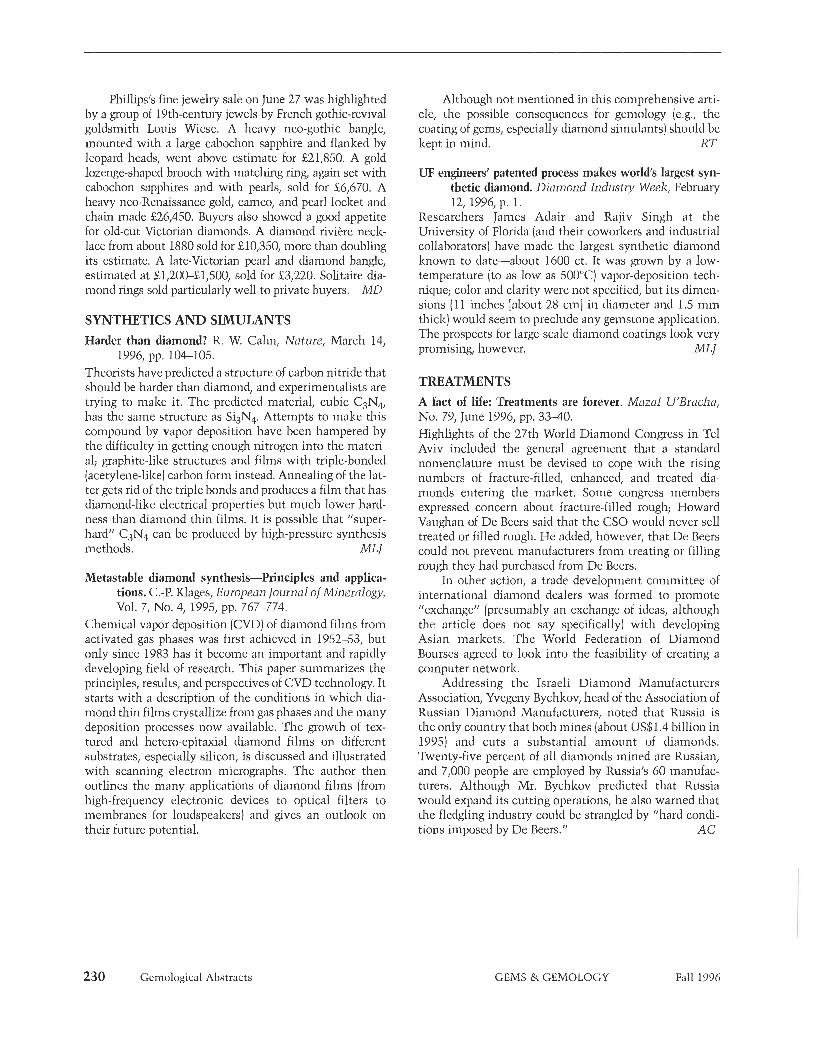
Phillips's fine jewelry sale on June 27 was highlighted by a group of 19th-century jewels by French gothic-revival goldsmith Louis Wiese. A heavy neo-gothic bangle, mounted with a large cabochon sapphire and flanked by leopard heads, went above estimate for £21,850 A gold lozenge-shaped brooch with matching ring, again set with cabochon sapphires and with pearls, sold for £6,670 A heavy neo-Renaissance gold, cameo, and pearl locket and chain made £26,450 Buyers also showed a good appetite for old-cut Victorian diamonds. A diamond riviere neclc- lace from about 1880 sold for £10,350 more than doubling its estimate. A late-Victorian pearl and diamond bangle, estimated at £1,200-£1,50 sold for £3,220 Solitaire dia- mond rings sold particularly well to private buyers, MD
SYNTHETICS AND SIMULANTS Harder than diamond? R. W. Cahn, Nature, March 14,
1996, pp. 104-105. Theorists have predicted a structure of carbon nitride that should be harder than diamond, and experimentalists are trying to make it. The predicted material, cubic C3N4, has the same structure as SiiN4. Attempts to make this compound by vapor deposition have been hampered by the difficulty in getting enough nitrogen into the materi- al; graphite-like structures and films with triple-bonded [acetylene-like) carbon form instead. Annealing of the lat- ter gets rid of the triple bonds and produces a film that has dian~ond-like electrical properties but much lower hard- ness than diamond thin films. It is possible that "s~iper- hard" C&, can be produced by high-pressure synthesis methods. ML1
Metastable diamond synthesis-Principles and applica- tions. C.-P. Klages, European Journal of Mineralogy, Vol. 7, No. 4, 1995, pp. 767-774.
Chemical vapor deposition (CVD] of diamond films from activated gas phases was first achieved in 1952-53, but only since 1983 has i t become an important and rapidly developing field of research. This paper summarizes the principles, results, and perspectives of CVD technology. It starts with a description of the conditions in which dia- mond thin films crystallize from gas phases and the many deposition processes now available. The growth of tex- tured and hetero-epitaxial diamond films on different substrates, especially silicon, is discussed and illustrated with scanning electron micrographs. The author then outlines the many applications of diamond films (from high-frequency electronic devices to optical filters to membranes for loudspeakers) and gives an outlook on their future potential.
Although not mentioned in this comprehensive arti- cle, the possible consequences for gemology (e.g., the coating of gems, especially diamond simulants) should be kept in mind. RT
UF engineers' patented process makes world's largest syn- thetic diamond. Diamond Industry Week, February 12, 1996, p. 1.
Researchers James Adair and Rajiv Singh at the University of Florida (and their coworkers and industrial collaborators) have made the largest synthetic diamond known to date-about 1600 ct. It was grown by a low- temperature (to cis low as 500°C vapor-deposition tech- nique; color and clarity were not specified, but its dimen- sions (11 inches [about 28 cm] in diameter and 1.5 min thick) would seem to preclude any gemstone application, The prospects for large-scale diamond coatings look very promising, however. MLl
TREATMENTS A fact of life: Treatments are forever. Mazal U'Bracha, No. 79, June 1996, pp. 33-40. Highlights of the 27th World Diamond Congress in Tel Aviv included the general agreement that a standard nomenclature must be devised to cope with the rising numbers of fracture-filled, enhanced, and treated dia- monds entering the market. Some congress members expressed concern about fracture-filled rough; Howard Vaughan of De Beers said that the CSO would never sell treated or filled rough. He added, however, that De Beers could not prevent manufacturers from treating or filling rough they had purchased from De Beers.
In other action, a trade development committee of international diamond dealers was formed to promote "exchange" (presumably an exchange of ideas, although the article does not say specifically) with developing Asian markets. The World Federation of Diamond Bourses agreed to look into the feasibility of creating a computer network.
Addressing the Israeli Diamond Manufacturers Association, Yvegeny Bychkov, head of the Association of Russian Diamond Manufacturers, noted that Russia is the only country that both mines (about US$1.4 billion in 1995) and cuts a substantial amount of diamonds. Twenty-five percent of all diamonds mined are Russian, and 7,000 people are employed by Russia's 60 manufac- turers. Although Mr. Bychkov predicted that Russia would expand its cutting operations, he also warned that the fledgling industry could be strangled by "hard condi- tions imposed by De Beers." A C
230 Gemological Abstracts GEMS &. GEMOLOGY Fall 1996


