The GROHE Installation/Troubleshooting Guide is designed to provide additional technical support to those who install, service and troubleshoot Grohe Products. The Guide is divided into four main categories: Bath/Shower, Custom Showers, Kitchen and Troubleshooting/Technical Tips allowing the user to easily find the corresponding technical information. If you do not find the information you require or if you need further direction, please contact the Grohe Technical Support Department for additional assistance. Grohe technical support can be reached at 630-582-7711 or 1-800-444-7643. Technical support is also available on the Grohe America website: www.groheamerica.com. Click on “Contact Us”. We hope you find this guide to be a valuable job aide and a convenient reference. The GROHE America Training Team
Transcript
The GROHE Installation/Troubleshooting Guide is designed to provide additional technical support to those who install, service and troubleshoot Grohe Products. The Guide is divided into four main categories: Bath/Shower, Custom Showers, Kitchen and Troubleshooting/Technical Tips allowing the user to easily find the corresponding technical information. If you do not find the information you require or if you need further direction, please contact the Grohe Technical Support Department for additional assistance. Grohe technical support can be reached at 630-582-7711 or 1-800-444-7643.
Technical support is also available on the Grohe America website: www.groheamerica.com. Click on “Contact Us”.
We hope you find this guide to be a valuable job aide and a convenient reference.
The GROHE America Training Team
�
Table of Contents
Bath/Shower
Thermostatic Valves
Flushing the Valve 1
Using a Twin Ell 2
Calibrating the Valve 3
Pressure Balance Valves
Placement of Valve & Shower Components 4
Custom Showers
Piping to Multiple Outlets/Valves 1
Installing Body Sprays 2
Positioning Guide 3
Kitchen
Installing a Ladylux Faucet 1
Index
�Index
Troubleshooting/Technical Tips
Troubleshooting
Water is all hot or all cold. No mixed water 1
Fluctuating water temperature/Cross Flow 2
Low water flow/Fluctuating temperature 3
Leaking shower outlets 4
Technical Tips
3/4" Thermostatic Valve on 1/2" Supplies 1
Valve Flow Rate/Shower Outlets 2
Flow Restrictors 3
PEX Tubing 4
�
Thermostatic ValvesFlushing the Valve
IMPORTANT!Flush valve prior to use STEP 1: Close service stop, remove the check
valve and clean the screen.
STEP 2: Insert plastic flush plug where the check valve was installed.
STEP 3: Open the service stop and flush the valve (Threads on the flush plug are for a hose, if needed).
STEP 4: Close the service stop, remove flush plug and reinstall the check valve.
Repeat the same steps for the other check valve
Bath/Shower
�Bath/Shower
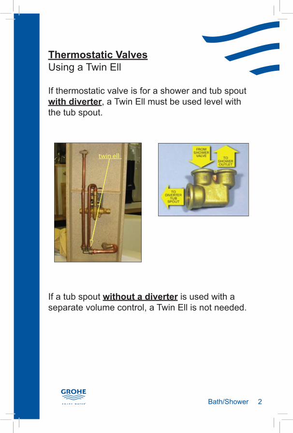
Thermostatic ValvesUsing a Twin Ell
If thermostatic valve is for a shower and tub spout with diverter, a Twin Ell must be used level with the tub spout.
If a tub spout without a diverter is used with a separate volume control, a Twin Ell is not needed.
twin ell
�Bath/Shower
Thermostatic ValvesCalibrating the Valve
STEP 1: Open volume control. Determine water temperature with thermometer.
STEP 2: Turn regulator knob until water is 100°F (38°C).
STEP 3: Install handle. Trim to read 100°F (38°C) at the 12 o’clock position.
�Bath/Shower
Pressure Balance ValvesPlacement of Valve/Shower Components
Shower/tub spout with diverterInstall pressure balance valve 8" to 12" (20cm to 30cm) from tub spout with diverter to avoid “stacking”. Shower outlet should be a minimum of 30" (76cm) above pressure balance valve.
30 inches(76 cm)
8-12 inches(20-30 cm)
Hand shower with wall unionInstall union above the pressure balance valve to avoid “stacking”
�Custom Showers
Custom ShowersPiping to Multiple Outlets/Valves
When piping to multiple outlets from a thermostatic valve, pipe from top or bottom, not both!
IMPORTANT! Drawing water from the top and the bottom at the same time may cause a noticeable water temperature difference.
When using more than one thermostatic valve in a shower, each valve needs its own set of hot and cold supply lines.
�Custom Showers
Custom ShowersInstalling Body Sprays
Two or more body sprays must be plumbed with a balancing loop. This ensures that each outlet delivers the same spray volume and temperature.
IMPORTANT!Do Not remove flow restrictors from body sprays.
�Custom Showers
Custom Showers Positioning Guide
The height of all shower users should be taken into accountShower head should be above tallest user but not out of reach for shorter usersTop body spray normally set at chest heightMiddle body spray normally set at waist or hip levelLowest body spray normally set at thigh heightThermostatic valve normally set at waist heightVolume control should be installed at a height that is convenient for the user—usually 6” to 8” (15cm to 20cm) higher than the thermostatic valve
A.
B.
C.D.
E.F.G.
�Kitchen
KitchenInstalling a Ladylux Faucet
Step 1: Place the faucet body on the counter and attach the mounting set. Make sure to install supplied o-ring seal between faucet body and counter.
Step 2: While holding on to the mounting set, insert the supplied tool into the neck of the faucet and start
turning. Within 2-3 turns the mounting set should start to thread onto the stem. Keep turning
until the faucet is firmly installed on the counter.
Use 7/8" (22mm) open-end wrench to firmly tighten faucet body to counter.
Step 3: Insert the hose into the spout.
Steps continued on Kitchen page 2
�Kitchen
KitchenInstalling a Ladylux Faucet
Step 4: Insert the hose into the spray head and thread
onto the coupling.
Step 5: Feed the hose through the faucet body.
Step 6: Attach the spout to the faucet body.
Step 7: Slide the pressure spring over the hose.
Step 8: Thread the quick connect onto the hose.
Step 9: Attach the other end of the quick connect to the water supply. Flush lines then connect the hot and cold supplies.
Installation is complete
�Troubleshooting
Troubleshooting
Symptom:Water is all hot or all cold. No mixed water.
Remedy:Check connections. Hot supply should be connected to hot inlet port and cold supply should be connected to cold inlet port.
If connections are incorrect reverse them or replace original cartridge with a reverse cartridge (diagram A).
If connections are correct, the temperature control knob may be damaged (diagram B).
Hot (W)
(H) on bottom (C) on bottom
Cold(K)
diagram A
diagram B
Do not put screw in green knob.
�Troubleshooting
Troubleshooting
Symptom: Fluctuating water temperature/ Cross Flow
Remedy: P If a recirculation system is installed, check the
return line to the water heater to ensure there is a check valve between the pump on the return line and the water heater.
P Try Isolating the thermostatic valve from the recirculation line. If the valve works properly, there is a problem with the recirculation system.
Note:Cross Flow can also result from another shower valve in the house with ineffective check valves or a stuck solenoid in the washing machine.
Check Valve
�Troubleshooting
Troubleshooting
Symptom:Low water flow/Fluctuating water temperature
Remedy: Clean check valve. Close service stops then remove and clean the check valves. While checks are removed, flush lines.
Check Valve Service Stop
�Troubleshooting
Troubleshooting
Symptom: Leaking shower outlets
Remedy:P Verify arrow on volume control valve body is
pointing up. The arrow indicates the direction of the water flow. If the volume control is installed upside down, shower outlets may leak.
P Check cartridge. Heat from the torch can damage the cartridge or shorten its life. IMPORTANT!Always remove the cartridge from the volume control before sweating into place.
Arrow on the volume control valve body
�Technical Tips
Technical TipsUsing a ¾" Thermostatic Valve on ½" Supplies
A ¾” valve used with ½” supplies will not perform at full capacity, but will still flow more water than a ½” valve.
It is not necessary to have ¾" supplies to use a ¾" valve, but when possible, this is preferred.
Copper Supply Line
Valve Flow @ 45 psi
Flow @ 60 psi
�/�" �/�" 18 gpm 20 gpm
�/�" �/�" 14* gpm 16* gpm
�/�" �/�" 11 gpm 12 gpm
*approximation
�Technical Tips
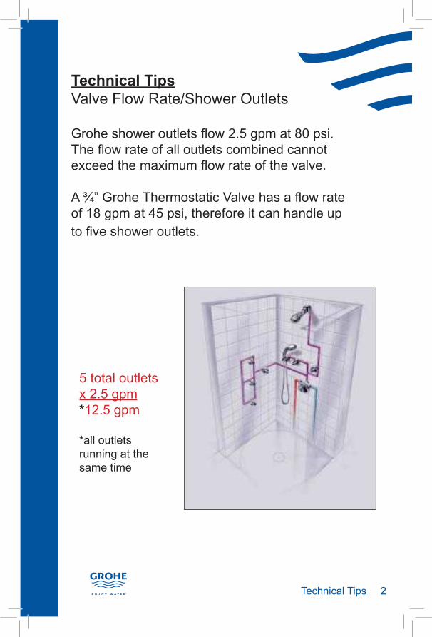
Technical TipsValve Flow Rate/Shower Outlets
Grohe shower outlets flow 2.5 gpm at 80 psi. The flow rate of all outlets combined cannot exceed the maximum flow rate of the valve.
A ¾” Grohe Thermostatic Valve has a flow rate of 18 gpm at 45 psi, therefore it can handle up to five shower outlets.
5 total outletsx 2.5 gpm*12.5 gpm
*all outlets running at the same time
�Technical Tips
Technical TipsFlow Restrictors
Removing flow restrictors will upset the balance of the system and may affect the overall shower performance.
Removing the flow restrictor from a Grohe hand shower will increase the flow rate from 2.5 gpm to approx. 5 gpm. Grohe Rainshower outlets will flow up to 15 gpm if the flow restrictor is removed.
IMPORTANT! If flow restrictors are removed, the total flow rate of the shower outlets may exceed the flow capacity of the valve thus resulting in the need for an additional valve.
10 total outletsx 2.5 gpm*25 gpm
*all outlets running at the same time
�Technical Tips
Technical TipsPEX Tubing
PEX is cross-linked Polyethylene. The process used to create PEX causes it to be more durable under extreme temperatures and chemical attack.
Application:The flexibility and strength of PEX at temperatures up to 200°F (93°C) makes it an ideal piping material for hot and cold water plumbing systems.
Sizing:Due to the restrictive nature of PEX insert fittings, Grohe recommends upsizing PEX pipe one size (i.e.: use ¾” PEX instead of ½” copper pipe).