14
The Guide to Refrigerated Purging Handbook 702-D EVAPORATOR COMPRESSOR RECEIVER CONDENSER
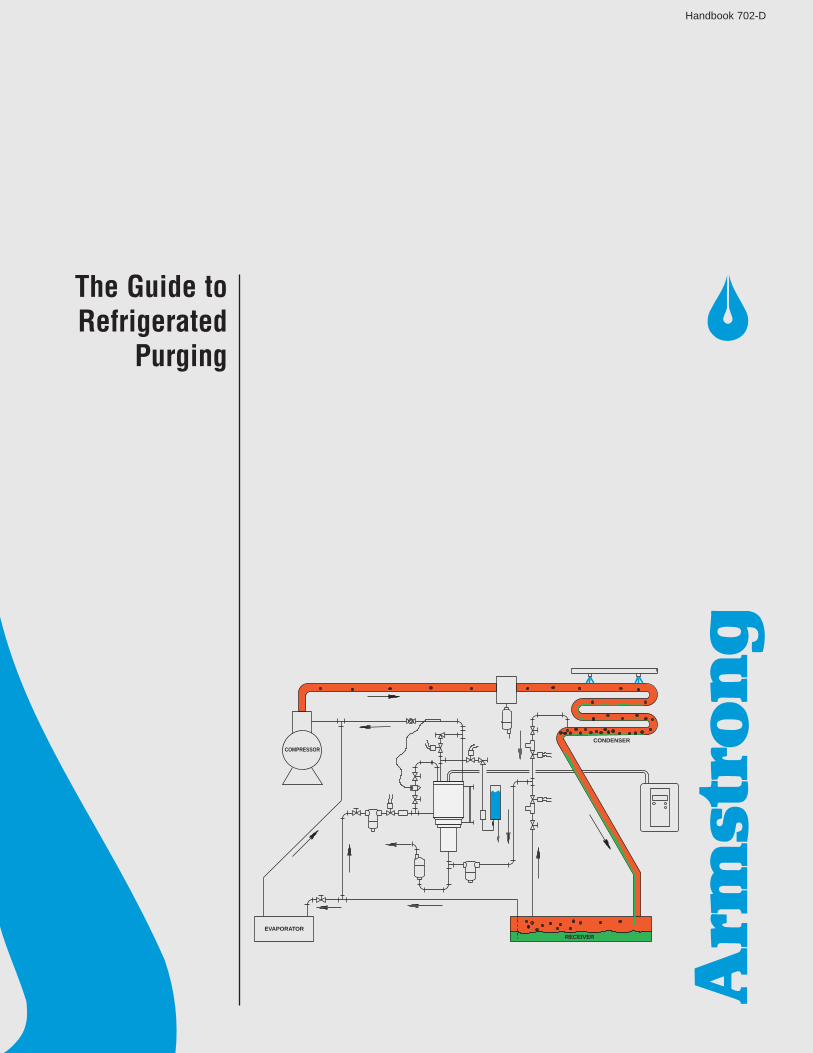
The Guide toRefrigerated
Purging
Handbook 702-D
EVAPORATOR
COMPRESSOR
RECEIVER
CONDENSER
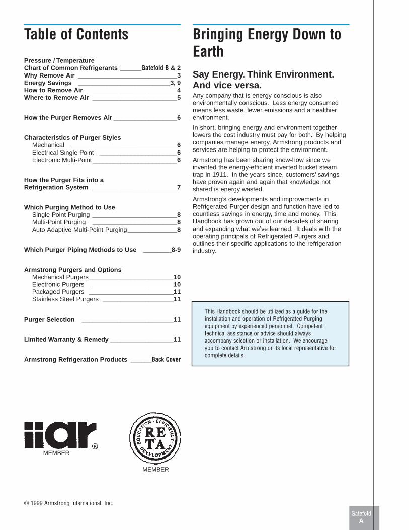
Table of Contents
Pressure / TemperatureChart of Common Refrigerants ______ Gatefold B & 2Why Remove Air ____________________________3Energy Savings __________________________3, 9How to Remove Air __________________________4Where to Remove Air ________________________5
How the Purger Removes Air __________________6
Characteristics of Purger StylesMechanical ______________________________6Electrical Single Point ______________________6Electronic Multi-Point________________________6
How the Purger Fits into aRefrigeration System ________________________7
Which Purging Method to UseSingle Point Purging ________________________8Multi-Point Purging ________________________8Auto Adaptive Multi-Point Purging______________8
Which Purger Piping Methods to Use ________8-9
Armstrong Purgers and OptionsMechanical Purgers________________________10Electronic Purgers ________________________10Packaged Purgers ________________________11Stainless Steel Purgers ____________________11
Purger Selection __________________________11
Limited Warranty & Remedy __________________11
Armstrong Refrigeration Products ______ Back Cover
Bringing Energy Down toEarthSay Energy. Think Environment.And vice versa.Any company that is energy conscious is alsoenvironmentally conscious. Less energy consumedmeans less waste, fewer emissions and a healthierenvironment.
In short, bringing energy and environment togetherlowers the cost industry must pay for both. By helpingcompanies manage energy, Armstrong products andservices are helping to protect the environment.
Armstrong has been sharing know-how since weinvented the energy-efficient inverted bucket steamtrap in 1911. In the years since, customers’ savingshave proven again and again that knowledge notshared is energy wasted.
Armstrong’s developments and improvements inRefrigerated Purger design and function have led tocountless savings in energy, time and money. ThisHandbook has grown out of our decades of sharingand expanding what we’ve learned. It deals with theoperating principals of Refrigerated Purgers andoutlines their specific applications to the refrigerationindustry.
This Handbook should be utilized as a guide for theinstallation and operation of Refrigerated Purgingequipment by experienced personnel. Competenttechnical assistance or advice should alwaysaccompany selection or installation. We encourageyou to contact Armstrong or its local representative forcomplete details.
GatefoldA
© 1999 Armstrong International, Inc.
MEMBER
MEMBER
GatefoldB
Temperature-Pressure Chart — Metric
Temp.REFRIGERANT
°C Ammonia Propane PropyleneR-717 R-22 R-134a R-502 R-290 R-1270
-46 -0.50 -0.22 -0.64 -0.03 -0.15 0.08-44 -0.44 -0.14 -0.59 0.07 -0.07 0.18-42 -0.37 -0.06 -0.55 0.17 0.01 0.29-40 -0.30 0.04 -0.50 0.28 0.10 0.41-38 -0.22 0.14 -0.44 0.40 0.20 0.53-36 -0.13 0.25 -0.38 0.53 0.30 0.66-34 -0.03 0.37 -0.31 0.67 0.42 0.80-32 0.07 0.49 -0.24 0.81 0.54 0.95-30 0.18 0.63 -0.17 0.97 0.66 1.11-28 0.30 0.77 -0.09 1.13 0.80 1.28-26 0.43 0.92 0.00 1.31 0.94 1.46-24 0.57 1.08 0.10 1.49 1.10 1.64-22 0.73 1.26 0.20 1.69 1.26 1.84-20 0.89 1.44 0.31 1.90 1.43 2.05-18 1.06 1.63 0.43 2.12 1.61 2.27-16 1.25 1.84 0.56 2.35 1.80 2.51-14 1.45 2.06 0.69 2.60 2.00 2.75-12 1.67 2.29 0.84 2.86 2.22 3.01-10 1.89 2.54 0.99 3.13 2.44 3.28-8 2.14 2.79 1.16 3.42 2.67 3.57-6 2.40 3.06 1.33 3.72 2.92 3.86-4 2.68 3.35 1.51 4.04 3.18 4.18-2 2.97 3.65 1.71 4.37 3.45 4.500 3.28 3.97 1.91 4.72 3.73 4.852 3.61 4.30 2.13 5.08 4.03 5.204 3.96 4.65 2.36 5.47 4.34 5.586 4.33 5.01 2.61 5.86 4.66 5.978 4.72 5.40 2.86 6.28 5.00 6.37
10 5.14 5.80 3.13 6.72 5.35 6.8012 5.57 6.22 3.42 7.17 5.72 7.2414 6.03 6.66 3.71 7.64 6.10 7.7016 6.52 7.11 4.03 8.14 6.50 8.1718 7.03 7.59 4.36 8.65 6.92 8.6720 7.56 8.09 4.70 9.18 7.35 9.1922 8.12 8.61 5.06 9.74 7.80 9.7224 8.71 9.15 5.44 10.31 8.27 10.2826 9.33 9.72 5.84 10.91 8.75 10.8528 9.98 10.30 6.25 11.53 9.25 11.4530 10.66 10.91 6.69 12.18 9.78 12.0732 11.37 11.54 7.14 12.84 10.32 12.7134 12.11 12.20 7.61 13.53 10.88 13.3836 12.89 12.89 8.10 14.25 11.46 14.0638 13.70 13.59 8.62 14.99 12.06 14.7740 14.54 14.33 9.15 15.76 12.68 15.5144 16.34 15.88 10.29 17.37 13.99 17.0548 18.29 17.54 11.51 19.09 15.38 18.7052 20.40 19.32 12.84 20.94 16.87 20.4656 22.68 21.23 14.27 22.90 18.46 22.3360 25.14 23.26 15.80 25.00 20.15 24.3164 27.79 25.43 17.45 27.25 21.94 26.42
All pressures: bar (gauge)
Ref.: ASHRAE 1997 Fundamentals Handbook
Table 2-1. Metric

2
Temperature-Pressure Chart
Temp.REFRIGERANT
°F Ammonia Propane PropyleneR-717 R-22 R-134a R-502 R-290 R-1270
-50 14.3 6.1 18.7 0.2 4.3 1.5-45 11.7 2.7 16.9 1.9 0.9 3.6-40 8.8 0.6 14.8 4.1 1.4 5.9-35 5.4 2.6 12.5 6.5 3.4 8.4-30 1.6 4.9 9.9 9.2 5.6 11.1-25 1.3 7.4 6.9 12.1 8.1 14.1-20 3.6 10.2 3.7 15.3 10.7 17.4-15 6.2 13.2 0.1 18.8 13.6 20.9-10 9.0 16.5 1.9 22.6 16.7 24.7-5 12.2 20.1 4.1 26.7 20.0 28.80 15.7 24.0 6.5 31.1 23.7 33.25 19.6 28.3 9.1 35.9 27.6 38.0
10 23.8 32.8 11.9 41.0 31.8 43.115 28.4 37.8 15.0 46.5 36.3 48.620 33.5 43.1 18.4 52.5 41.1 54.425 39.0 48.8 22.1 58.8 46.3 60.630 45.0 55.0 26.1 65.6 51.8 67.335 51.6 61.5 30.4 72.8 57.7 74.440 58.6 68.6 35.0 80.5 63.9 81.945 66.3 76.1 40.0 88.7 70.6 89.850 74.5 84.1 45.4 97.4 77.6 98.355 83.4 92.6 51.2 106.6 85.1 107.260 92.9 101.7 57.4 116.4 93.0 116.765 103.2 111.3 64.0 126.7 101.4 126.770 114.1 121.5 71.1 137.6 110.2 137.275 125.9 132.3 78.6 149.1 119.5 148.380 138.4 143.7 86.7 161.2 129.3 159.985 151.8 155.8 95.2 174.0 139.6 172.290 166.0 168.5 104.3 187.4 150.5 185.195 181.2 181.9 113.9 201.4 161.9 198.6
100 197.3 196.0 124.1 216.2 173.9 212.8105 214.4 210.8 134.9 231.7 186.4 227.7110 232.5 226.4 146.4 247.9 199.6 243.2115 251.6 242.8 158.4 264.9 213.4 259.5120 271.9 260.0 171.1 282.7 227.8 276.5125 293.3 278.0 184.6 301.4 242.9 294.2130 315.8 296.9 198.7 320.8 258.6 312.7135 339.6 316.7 213.6 341.2 275.1 332.0140 364.6 337.4 229.2 362.6 292.3 352.3145 391.0 359.0 245.6 385.0 310.2 373.6150 418.7 381.6 262.9 408.4 328.9 396.2
Vacuum: Positive pressures: Inches of mercury Pounds per square inch (gauge)Bold italic figures Black regular figures
Ref.: ASHRAE 1997 Fundamentals Handbook
Table 2-1.
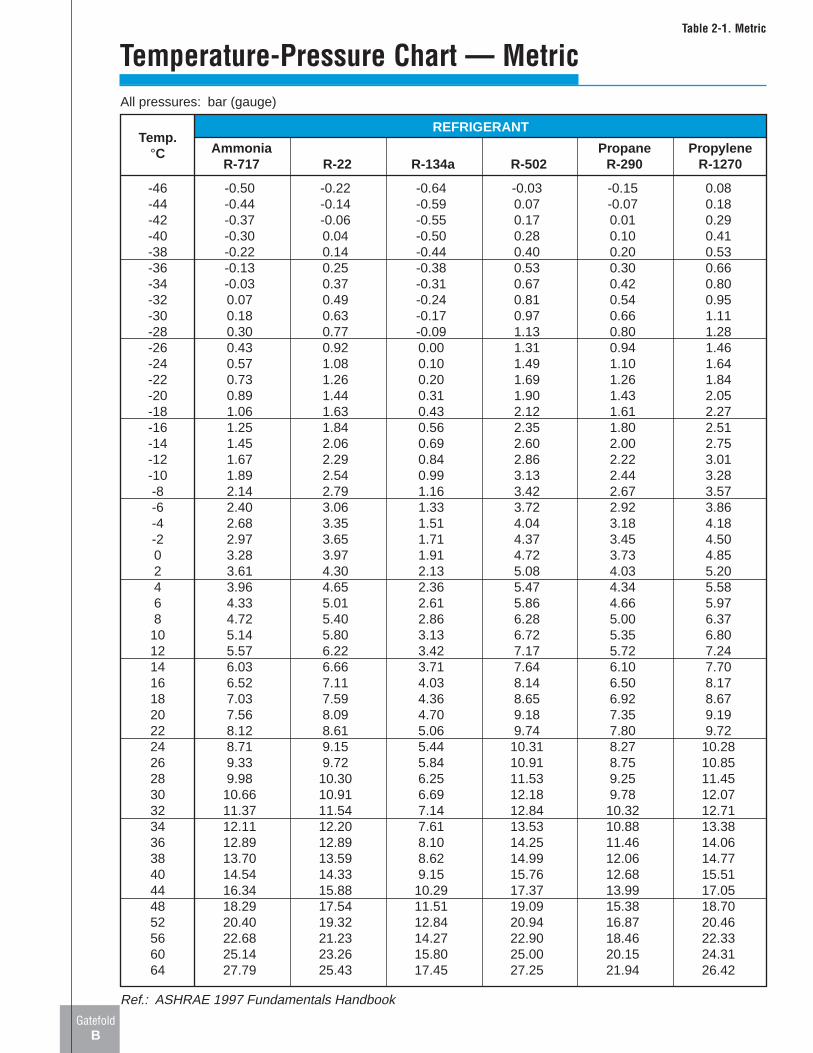
In this discussion of purging and purgers, the word “Air”is intended to cover all non-condensable gases in a refrigeration system.
“Air” in the condenser will raise headpressure, mainly due to its insulatingproperties. Air molecules in the gasfrom the compressor will be blown tothe quiet end of the condenser. Thisair accumulates on the heat transfersurfaces as shown in Fig. 3-1.
Fig. 3-1. Air (black dots) keeps refrigerantgas away from the condensing surface,effectively reducing condenser size.
When condenser surfaces are insu-lated with air, the effective condensersize is reduced. This size reduction isoffset by increasing the temperatureand pressure of the refrigerant gas –this is an expensive luxury.
Air in the Condenser isExpensive.
Power Costs.For each 4 lbs. of excess headpressure caused by air increasescompressor power costs by 2% andreduces compressor capacity by 1%.And, losses caused by reducedcapacity may far exceed the extracosts for operating the compressor.
Cooling Water.More cooling water will improvecondenser performance but coolingwater is expensive also!
Wear and Tear.Excess head pressure puts morestrain on bearing and drive motors.Belt life is shortened and gasket sealsare ruptured.
High Temperature.Increased pressure leads toincreased temperature, whichshortens the life of compressor valvesand promotes the breakdown oflubricating oil.
Gasket Failure.Increased head pressure increasesthe likelihood of premature gasketfailures.
Explosions.Some so-called “ammonia explosions”have been traced to the accumulationof non-condensable hydrogen.
Where Does Air Come From?Air can enter any refrigeration system:
1. By leaking through condenserseals and valve packings whensuction pressure is belowatmospheric conditions.
2. When the system is open forrepairs, coil cleaning, equipmentadditions, etc.
3. When charging by refrigeranttrucks.
4. When adding oil.
5. By the breakdown of refrigerant orlubricating oil.
6. From impurities in the refrigerant.
How To Tell If Air Is Present.To determine the amount air in arefrigeration system, check thecondenser pressure and temperatureof the refrigerant leaving the con-denser against the data in Table 2-1(Gatefold B for metric). If, for exampleyour ammonia temperature is 85°F,the theoretical condenser pressureshould be 151.8 psig. If your gaugereads 171 psig, you have 20-psiexcess pressure that is increasingpower costs 10% and reducingcompressor capacity by 5%.
If you do not have digital readouts orliquid line mercury well, reasonablygood readings can be obtained bystrapping the bulb of an immersionthermometer to the liquid line. Coverthe bulb with about 10 of permagumand then insulate with heavy cloth. In3 to 4 minutes, it should be possibleto take a reading accurate to within 1⁄2to 3⁄4 of a degree.
Caution - Air is not the only cause ofexcessive condenser pressure. A condenserthat is too small or a condenser with fouledand scaled tubes will give excess pressurewithout air. Air, however is by far the mostlikely cause of excess condenser pressure,and the air must be purged before the headpressure can be reduced to the proper level.
Pressure ReductionPSI
$0.03 $0.04 $0.05 $0.06 $0.08 $0.10 $0.12
5 $400 $530 $670 $800 $1070 $1330 $160010 $800 $1070 $1330 $1600 $2130 $2660 $320015 $1200 $1600 $2000 $2400 $3200 $4000 $480020 $1600 $2130 $2660 $3200 $4260 $5330 $6390
Annual dollar savings* per 100 tons, at 6,500 hr./yr.Power cost per kWh
Table 3-1 shows the savings (in U.S. Dollars) in compressor operating costs achieved by usinga refrigerated purge to reduce excess high side pressure.
Savings: Compressor Operating Costs
Why Purge Air From Your Refrigeration System?
3
KEY
Water
Refrigerant
Air
Air in tube ofevaporativecondenser insulatesthe surface
Air surrounding tubeof a horizontal shelland tube or avertical condenser
4
Manual PurgingManual purging is too expensive andtoo troublesome except for very smallsystems. It does not take a largepercentage of air to cause a notice-able increase in high-side pressure.Manual purging at the condenser orreceiver will discharge much morerefrigerant than air into the atmos-phere. Worse yet, as the air is purgedfrom the system, even larger quan-tities of refrigerant must be wasted toget rid of the remaining air. Besideswasting refrigerant, manual purging:
• Takes a lot of valuable time.
• Does not totally eliminate air.
• Permits escape of refrigerant gasthat may be dangerous anddisagreeable to people and theenvironment, and may also beillegal.
• Is easily neglected until thepresence of air in the systemcauses problems.
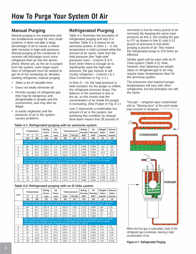
Refrigerated PurgingTable 4-1 illustrates the principles ofrefrigerated purging and why it isneeded. Table 4-1 is based on anammonia system. In lines 1 – 4, thetemperature is held constant while theamount of air varies. Note how thetotal pressure (the “high-side”pressure) rises – Column E & F.Even when there is enough air tosignificantly raise the high-sidepressure, the gas mixture is stillmostly refrigerant – Column I & J.(See Condenser in Fig. 4-1.)
In lines 5 – 10. the total pressure isheld constant. As the purger is chilled,the refrigerant pressure drops. Thebalance of the pressure is due to the air, so this means that theconcentration of air inside the purgeris increasing. (See Purger in Fig. 4-1.)
Line 2 represents a moderately lowamount of air in the system, butachieving this condition by manualblow-down means that 28 pounds of
ammonia is lost for every pound of airremoved. By keeping the same totalpressure as line 2, but cooling the gasto 0°F as shown in line 8, only 0.13pound of ammonia is lost whenpurging a pound of air. This meansthe refrigerated purge is 215 times aseffective.
Similar gains will be seen with an R-134a system (Table 4-2). Note,however, that obtaining low weightratios of refrigerant gas to air mayrequire lower temperatures than forthe ammonia system.
The pressures and required purgertemperatures will vary with otherrefrigerants, but the principles are stillthe same.
How To Purge Your System Of Air
CONDENSER
PURGER
TemperatureRefrig. Air
Total pressureRefrig. Air Weight Volume
Press. Press. Density Density Ratio RatioLine
°F °C psia psia psia bar (a) lb/ft 3 lb/ft 3 Gas/air Gas/air(A) (B) (C) (D) (E) (F) (G) (H) (I) (J)
Keeping the temperature (Cols. A and B) constant as we vary the amount of air (Col. D), note theeffect on total pressure (Cols. E and F) and on the ratios of refrigerant gas to air (Cols. I and J):
1 85 29.4 166.5 1.0 167.5 11.55 0.556 0.005 112 1672 85 29.4 166.5 4.0 170.5 11.76 0.556 0.020 28 423 85 29.4 166.5 8.0 174.5 12.03 0.556 0.040 14.0 20.84 85 29.4 166.5 16.0 182.5 12.59 0.556 0.079 7.0 10.4
Now, holding total pressure (Cols. E and F) constant, we reduce the temperature (Cols. A and B).This reduces the refrigerant pressure (Col. C) and allows the air pressure (Col. D) to increase,dramatically reducing the ratios of refrigerant gas to air (Cols. I and J):
5 85 29.4 166.5 4.0 170.5 11.76 0.556 0.020 28 426 50 10.0 89.2 81.3 170.5 11.76 0.304 0.430 0.71 1.107 10 -12.2 38.5 132.0 170.5 11.76 0.137 0.758 0.18 0.298 0 -17.8 30.4 140.1 170.5 11.76 0.110 0.822 0.13 0.229 -10 -23.3 23.7 146.8 170.5 11.76 0.087 0.881 0.099 0.16
10 -20 -28.9 18.3 152.2 170.5 11.76 0.068 0.934 0.073 0.120
Table 4-1: Refrigerated purging with an ammonia system
TemperatureRefrig. Air
Total pressureRefrig. Air Weight Volume
Press. Press. Density Density Ratio RatioLine
°F °C psia psia psia bar (a) lb/ft 3 lb/ft 3 Gas/air Gas/air(A) (B) (C) (D) (E) (F) (G) (H) (I) (J)
Keeping the temperature (Cols. A and B) constant as we vary the amount of air (Col. D), note theeffect on total pressure (Cols. E and F) and on the ratios of refrigerant gas to air (Cols. I and J):
1 80 26.7 101.4 1.0 102.4 7.06 2.121 0.005 424 1012 80 26.7 101.4 4.0 105.4 7.27 2.121 0.020 106 253 80 26.7 101.4 8.0 109.4 7.54 2.121 0.040 53 12.74 80 26.7 101.4 16.0 117.4 8.09 2.121 0.080 27 6.3
Now, holding total pressure (Cols. E and F) constant, we reduce the temperature (Cols. A and B).This reduces the refrigerant pressure (Col. C) and allows the air pressure (Col. D) to increase,dramatically reducing the ratios of refrigerant gas to air (Cols. I and J):
5 80 26.7 101.4 4.0 105.4 7.27 2.121 0.020 106 256 50 10.0 60.1 45.3 105.4 7.27 1.262 0.240 5.27 1.337 20 -6.7 33.1 72.3 105.4 7.27 0.709 0.406 1.74 0.468 0 -17.8 21.2 84.2 105.4 7.27 0.463 0.494 0.94 0.259 -20 -28.9 12.9 92.5 105.4 7.27 0.290 0.567 0.51 0.14
10 -40 -40.0 7.4 97.9 105.4 7.27 0.173 0.630 0.27 0.076
Table 4-2: Refrigerated purging with an R-134a system
When the foul gas is subcooled, most of therefrigerant gas condenses, leaving a highconcentration of air.
Figure 4-1. Refrigerated Purging.
“Foul gas” – refrigerant vapor contaminatedwith air. “Blowing down” at this point wasteslarge amounts of refrigerant.
Purge Connections for Condensers
5
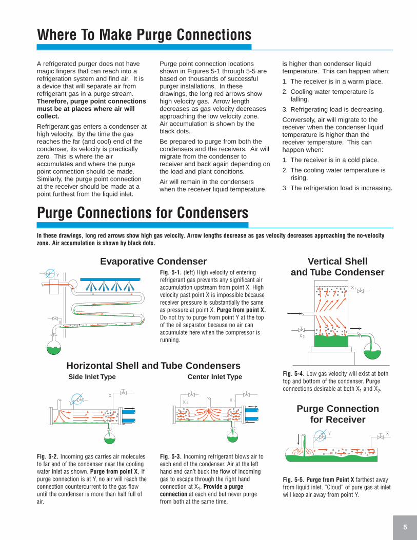
A refrigerated purger does not havemagic fingers that can reach into arefrigeration system and find air. It isa device that will separate air fromrefrigerant gas in a purge stream.Therefore, purge point connectionsmust be at places where air willcollect.
Refrigerant gas enters a condenser athigh velocity. By the time the gasreaches the far (and cool) end of thecondenser, its velocity is practicallyzero. This is where the airaccumulates and where the purgepoint connection should be made.Similarly, the purge point connectionat the receiver should be made at apoint furthest from the liquid inlet.
Purge point connection locationsshown in Figures 5-1 through 5-5 arebased on thousands of successfulpurger installations. In thesedrawings, the long red arrows showhigh velocity gas. Arrow lengthdecreases as gas velocity decreasesapproaching the low velocity zone.Air accumulation is shown by theblack dots.
Be prepared to purge from both thecondensers and the receivers. Air willmigrate from the condenser toreceiver and back again depending onthe load and plant conditions.
Air will remain in the condenserswhen the receiver liquid temperature
is higher than condenser liquidtemperature. This can happen when:
1. The receiver is in a warm place.
2. Cooling water temperature isfalling.
3. Refrigerating load is decreasing.
Conversely, air will migrate to thereceiver when the condenser liquidtemperature is higher than thereceiver temperature. This canhappen when:
1. The receiver is in a cold place.
2. The cooling water temperature isrising.
3. The refrigeration load is increasing.
Fig. 5-1. (left) High velocity of enteringrefrigerant gas prevents any significant airaccumulation upstream from point X. Highvelocity past point X is impossible becausereceiver pressure is substantially the sameas pressure at point X. Purge from point X.Do not try to purge from point Y at the topof the oil separator because no air canaccumulate here when the compressor isrunning.
Evaporative Condenser
Horizontal Shell and Tube CondensersSide Inlet Type Center Inlet Type
Purge Connection for Receiver
Vertical Shell and Tube Condenser
Fig. 5-4. Low gas velocity will exist at bothtop and bottom of the condenser. Purgeconnections desirable at both X1 and X2.
Fig. 5-5. Purge from Point X farthest awayfrom liquid inlet. “Cloud” of pure gas at inletwill keep air away from point Y.
Fig. 5-2. Incoming gas carries air moleculesto far end of the condenser near the coolingwater inlet as shown. Purge from point X. Ifpurge connection is at Y, no air will reach theconnection countercurrent to the gas flowuntil the condenser is more than half full ofair.
Fig. 5-3. Incoming refrigerant blows air toeach end of the condenser. Air at the lefthand end can’t buck the flow of incominggas to escape through the right handconnection at X1. Provide a purgeconnection at each end but never purge from both at the same time.
Where To Make Purge Connections
In these drawings, long red arrows show high gas velocity. Arrow lengths decrease as gas velocity decreases approaching the no-velocityzone. Air accumulation is shown by black dots.
How The Armstrong Purger RemovesAir From Refrigerant Gasxxxxxxxxxxx
6
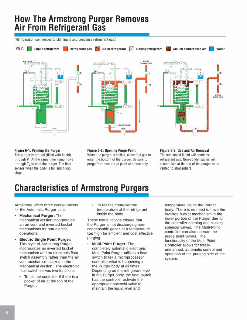
Figure 6-1. Priming the PurgerThe purger is primed (filled with liquid)through P. At the same time liquid flowsthrough Tx to cool the purger. The floatsenses when the body is full and fillingstops.
Figure 6-2. Opening Purge PointWhen the purger is chilled, allow foul gas toenter the bottom of the purger. Be sure topurge from one purge point at a time only.
Figure 6-3. Gas and Air RemovalThe subcooled liquid will condenserefrigerant gas. Non-condensables willaccumulate at the top of the purger to bevented to atmosphere.
Characteristics of Armstrong Purgers
Armstrong offers three configurationsfor the Automatic Purger Line:
• Mechanical Purger: Themechanical version incorporatesan air vent and inverted bucketmechanisms for non-electricoperations.
• Electric Single Point Purger:This style of Armstrong Purgerincorporates an inverted bucketmechanism and an electronic floatswitch assembly rather than the airvent mechanism utilized in theMechanical version. The electronicfloat switch serves two functions:
• To tell the controller if there is apocket of air at the top of thePurger;
• To tell the controller thetemperature of the refrigerantinside the body.
These two functions ensure that the Purger is not discharging non-condensable gases at a temperaturetoo high for efficient and cost effectivepurging.
• Multi-Point Purger: Thecompletely automatic electronicMulti-Point Purger utilizes a floatswitch to tell a microprocessorcontroller what is happening in the Purger body at all times.Depending on the refrigerant levelin the Purger body, the float switchhas the controller activate theappropriate solenoid valve tomaintain the liquid level and
temperature inside the Purgerbody. There is no need to have theinverted bucket mechanism in thelower portion of the Purger due tothe controller opening and closingsolenoid valves. The Multi-Pointcontroller can also operate thepurge point valves. Thefunctionality of the Multi-PointController allows for totallyunmanned, automatic control andoperation of the purging side of thesystem.
Liquid refrigerant Refrigerant gas Air in refrigerant Boiling refrigerant Chilled compressed air WaterKEY:
AIR VALVE
B
B1
P
Tx
T2SC
LIQUID VALVE
B
B1
P
Tx
T2SC
FROMCONDENSER
FROMRECEIVER
B
B1
P
Tx
T2SC
(Refrigeration coil needed to chill liquid and condense refrigerant gas.)
How The Armstrong Purger Fits IntoA Refrigeration System xxxxxxxxxxx
7
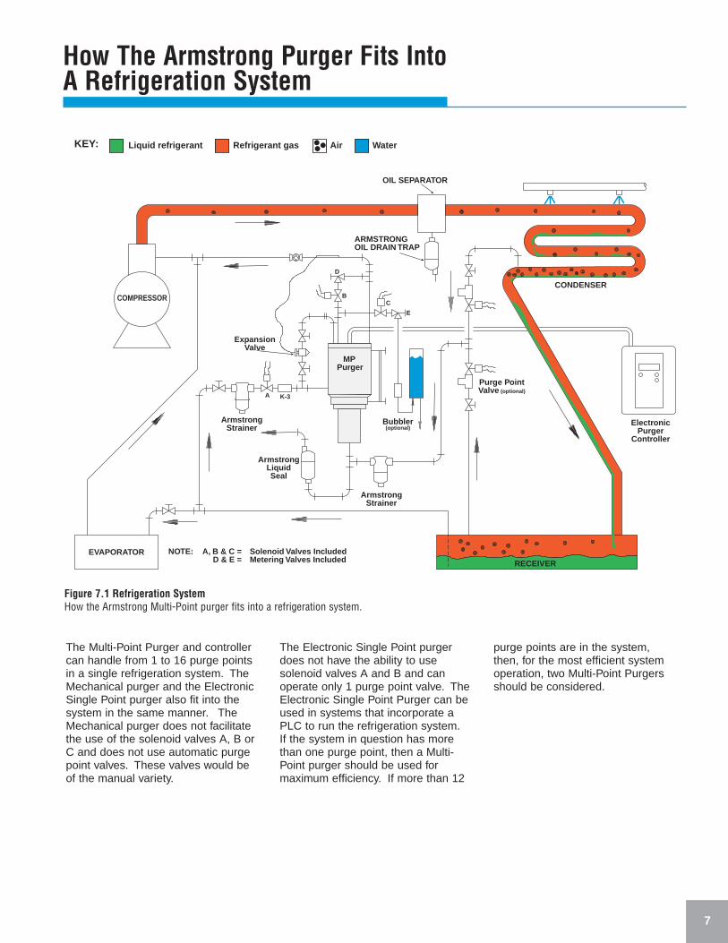
The Multi-Point Purger and controllercan handle from 1 to 16 purge pointsin a single refrigeration system. TheMechanical purger and the ElectronicSingle Point purger also fit into thesystem in the same manner. TheMechanical purger does not facilitatethe use of the solenoid valves A, B orC and does not use automatic purgepoint valves. These valves would beof the manual variety.
The Electronic Single Point purgerdoes not have the ability to usesolenoid valves A and B and canoperate only 1 purge point valve. TheElectronic Single Point Purger can beused in systems that incorporate aPLC to run the refrigeration system.If the system in question has morethan one purge point, then a Multi-Point purger should be used formaximum efficiency. If more than 12
purge points are in the system, then, for the most efficient systemoperation, two Multi-Point Purgersshould be considered.
EVAPORATOR
COMPRESSOR
RECEIVER
CONDENSER
OIL SEPARATOR
ARMSTRONGOIL DRAIN TRAP
ElectronicPurger
Controller
Purge PointValve (optional)
Bubbler(optional)
ArmstrongStrainer
ArmstrongLiquidSeal
ArmstrongStrainer
ExpansionValve
MPPurger
NOTE: A, B & C = Solenoid Valves IncludedD & E = Metering Valves Included
D
BC
E
A K-3
Liquid refrigerant Refrigerant gas Air WaterKEY:
Figure 7.1 Refrigeration SystemHow the Armstrong Multi-Point purger fits into a refrigeration system.
DIFFERENTIALVALVE
K-3
B
B1
Tx
D
C
T2SC
T2SC
LIQUIDSEALTRAP
Single Point PurgingPurging several points at the sametime would result in flow of air fromonly the purge point at the highestpressure, even though suchdifferences of pressure are veryslight. There would be no flow of airfrom the other purge points and theconcentration of air would continue toincrease in these components. Withthat in mind, it is only feasible andeconomical to purge from a singlepoint at a time.
Without an automatic system, eachpurge point valve must be openedand then closed independent of theothers manually. This can mean thatsome purge points do not get purgeduntil it is convenient for themaintenance personnel to get there.
For smaller systems with only onecondenser purge point, this is not aconcern. For larger systems, this cancause delays in air removal, whichleads to decreased system efficiency.
Multi-Point PurgingWith multiple condensers, receivers,etc., it is difficult to determine theexact location of air. Condenserpiping design, componentarrangement and operation affects thelocation of air concentrations.
Seasonal weather changes have anadded effect on the location of the air.In summer, the air may be driven tothe cooler, higher-pressure receiverslocated inside the building. In winter,the opposite may be true. The airmay migrate to the cooler outdoorcondensers, especially during offcycles. Therefore it is important topurge regularly and frequently eachpurge point in the system, one at atime, to ensure that all the air isremoved from every possible location.
There are two common ways toautomatically purge multiple points.An automatic electronic controllerbeing one way and the other being aPLC system.
Auto AdaptiveMulti-Point PurgingThe Armstrong Multi-Point Purgerautomatically adapts the samplingfrequency of individual purge pointsbased on that particular pointshistorical need for purging.
The Auto Adaptive purge systemaccomplishes this by rememberinghow long each purge point haspurged. The sequence of purgingeach point is based on that data. Thefirst point purged on subsequentcycles is the point that historicallyrequired the most purging time on thelast cycle. Because of its uniquelearning capability, it is not necessaryto set or even seasonally adjusttimers to accomplish high efficiencypurging. A smaller purger can noweffectively purge a much largersystem.
8
Which Purger Piping Method To Use
The Armstrong series of purgers may be piped for use in eitherHIGH DIFFERENTIAL or LOW DIFFERENTIAL systems. TheArmstrong purgers may also be used in systems where onerefrigerant is used to cool another refrigerant or gas.
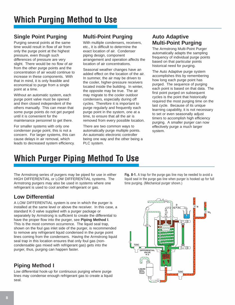
Low DifferentialA LOW DIFFERENTIAL system is one in which the purger isinstalled at the same level or above the receiver. In this case, astandard K-3 valve supplied with a purger package orseparately by Armstrong is sufficient to create the differential tohave the proper flow into the purger, see Piping Method I .This is the most common occurrence. The liquid seal trap,shown on the foul gas inlet side of the purger, is recommendedto remove any refrigerant liquid condensed in the purge pointlines coming from the condensers. Having the Armstrong liquidseal trap in this location ensures that only foul gas (non-condensable gas mixed with refrigerant gas) gets into thepurger, thus, purging can happen faster.
Which Purging Method to Use
Piping Method ILow differential hook-up for continuous purging where purgelines may condense enough refrigerant gas to create a liquidseal.
Fig. 8-1. A trap for the purge gas line may be needed to avoid aliquid seal in the purge gas line when purger is hooked up for fulltime purging. (Mechanical purger shown.)
9
FROM CONDENSER
DPR
T2SC
C
D K-1B1 B
T2SC
RECEIVERON ROOF
B
T2SC
B1
Tx
D
C
AA
P
TO "X"SUCTION FROM "Y"
CONDENSER
FROM "X"RECEIVER
"Y" RECEIVER
Which Purger Piping Method To Use (continued)
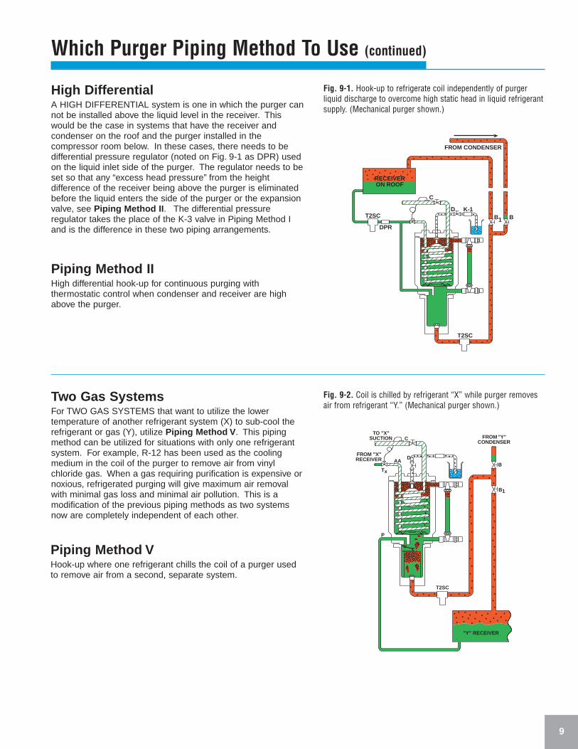
Fig. 9-1. Hook-up to refrigerate coil independently of purgerliquid discharge to overcome high static head in liquid refrigerantsupply. (Mechanical purger shown.)
Fig. 9-2. Coil is chilled by refrigerant “X” while purger removesair from refrigerant “Y.” (Mechanical purger shown.)
Piping Method IIHigh differential hook-up for continuous purging withthermostatic control when condenser and receiver are highabove the purger.
Piping Method VHook-up where one refrigerant chills the coil of a purger usedto remove air from a second, separate system.
High DifferentialA HIGH DIFFERENTIAL system is one in which the purger cannot be installed above the liquid level in the receiver. Thiswould be the case in systems that have the receiver andcondenser on the roof and the purger installed in thecompressor room below. In these cases, there needs to bedifferential pressure regulator (noted on Fig. 9-1 as DPR) usedon the liquid inlet side of the purger. The regulator needs to beset so that any “excess head pressure” from the heightdifference of the receiver being above the purger is eliminatedbefore the liquid enters the side of the purger or the expansionvalve, see Piping Method II . The differential pressureregulator takes the place of the K-3 valve in Piping Method Iand is the difference in these two piping arrangements.
Two Gas SystemsFor TWO GAS SYSTEMS that want to utilize the lowertemperature of another refrigerant system (X) to sub-cool therefrigerant or gas (Y), utilize Piping Method V . This pipingmethod can be utilized for situations with only one refrigerantsystem. For example, R-12 has been used as the coolingmedium in the coil of the purger to remove air from vinylchloride gas. When a gas requiring purification is expensive ornoxious, refrigerated purging will give maximum air removalwith minimal gas loss and minimal air pollution. This is amodification of the previous piping methods as two systemsnow are completely independent of each other.
Armstrong Purgers and Options Available
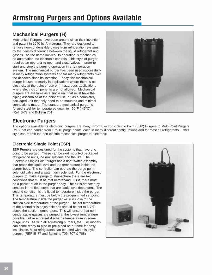
Mechanical Purgers (H)Mechanical Purgers have been around since their inventionand patent in 1940 by Armstrong. They are designed toremove non-condensable gases from refrigeration systemsby the density difference between the liquid refrigerant andgasses. As the name implies, its operation is mechanical,no automation, no electronic controls. This style of purgerrequires an operator to open and close valves in order tostart and stop the purging operation in a refrigerationsystem. The mechanical purger has been used successfullyin many refrigeration systems and for many refrigerants overthe decades since its invention. Today, the mechanicalpurger is used primarily in applications where there is noelectricity at the point of use or in hazardous applicationswhere electric components are not allowed. Mechanicalpurgers are available as a single unit that must have thepiping assembled at the point of use, or, as a completelypackaged unit that only need to be mounted and minimalconnections made. The standard mechanical purger isforged steel for temperatures down to –50°F (-45°C).(Ref IB-72 and Bulletin 701)
Electronic PurgersThe options available for electronic purgers are many. From Electronic Single Point (ESP) Purgers to Multi-Point Purgers(MP) that can handle from 1 to 16 purge points, each in many different configurations and for most all refrigerants. Eitherstyle can retrofit the non-electric mechanical purger to electronic.
Electronic Single Point (ESP)ESP Purgers are designed for the systems that have onepoint to be purged. These can be skid mounted packagedrefrigeration units, ice rink systems and the like. TheElectronic Single Point purger has a float switch assemblythat reads the liquid level and the temperature inside thepurger body. The controller can operate the purge pointsolenoid valve and a water flush solenoid. For the electronicpurgers to make a purge to atmosphere there are twoconditions that must be met beforehand. First, there mustbe a pocket of air in the purger body. The air is detected bysensors in the float stem that are liquid level dependent. Thesecond condition is the liquid temperature inside the purger.This temperature must be below the programmed set point.The temperature inside the purger will run close to thesuction side temperature of the purger. The set temperatureof the controller is adjustable and should be set to 5-7°Fabove the suction temperature. This will ensure that non-condensable gasses are purged at the lowest temperaturepossible, unlike a pre-set discharge temperature in somepurge units. As with all Armstrong purgers, the ESP modelscan come ready to pipe or pre-piped on a frame for easyinstallation. Most refrigerants can be used with this stylepurger. (REF IB-77 and Bulletins 706, 707 & 708)
10
11
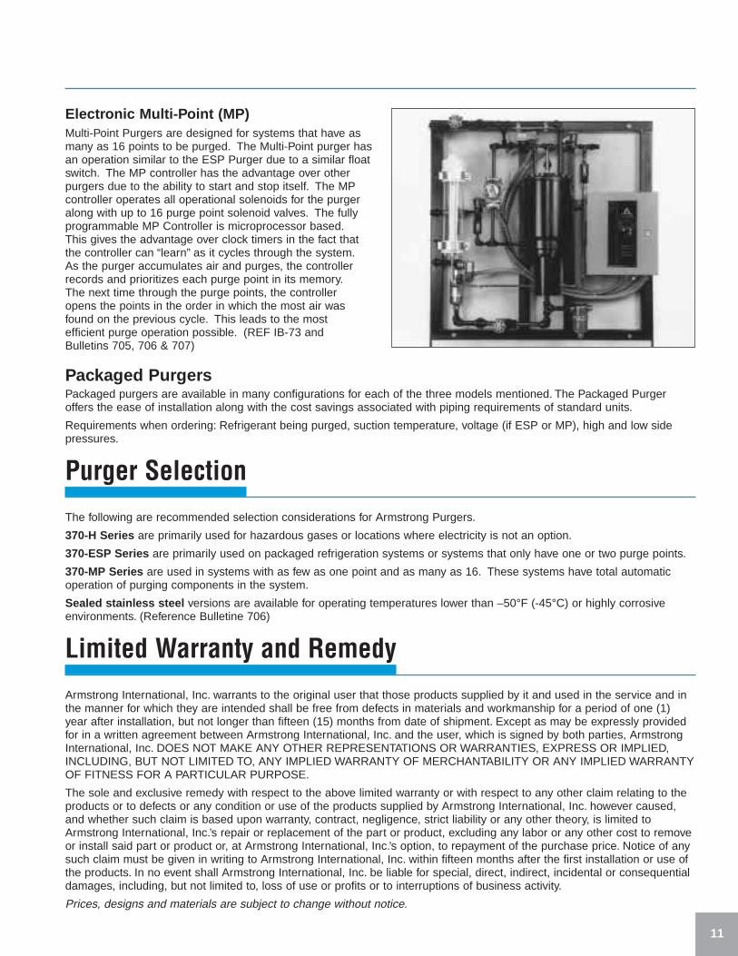
Electronic Multi-Point (MP)Multi-Point Purgers are designed for systems that have asmany as 16 points to be purged. The Multi-Point purger hasan operation similar to the ESP Purger due to a similar floatswitch. The MP controller has the advantage over otherpurgers due to the ability to start and stop itself. The MPcontroller operates all operational solenoids for the purgeralong with up to 16 purge point solenoid valves. The fullyprogrammable MP Controller is microprocessor based.This gives the advantage over clock timers in the fact thatthe controller can “learn” as it cycles through the system.As the purger accumulates air and purges, the controllerrecords and prioritizes each purge point in its memory.The next time through the purge points, the controller opens the points in the order in which the most air wasfound on the previous cycle. This leads to the most efficient purge operation possible. (REF IB-73 and Bulletins 705, 706 & 707)
Packaged PurgersPackaged purgers are available in many configurations for each of the three models mentioned. The Packaged Purgeroffers the ease of installation along with the cost savings associated with piping requirements of standard units.
Requirements when ordering: Refrigerant being purged, suction temperature, voltage (if ESP or MP), high and low sidepressures.
Purger SelectionThe following are recommended selection considerations for Armstrong Purgers.
370-H Series are primarily used for hazardous gases or locations where electricity is not an option.
370-ESP Series are primarily used on packaged refrigeration systems or systems that only have one or two purge points.
370-MP Series are used in systems with as few as one point and as many as 16. These systems have total automaticoperation of purging components in the system.
Sealed stainless steel versions are available for operating temperatures lower than –50°F (-45°C) or highly corrosiveenvironments. (Reference Bulletine 706)
Limited Warranty and RemedyArmstrong International, Inc. warrants to the original user that those products supplied by it and used in the service and inthe manner for which they are intended shall be free from defects in materials and workmanship for a period of one (1)year after installation, but not longer than fifteen (15) months from date of shipment. Except as may be expressly providedfor in a written agreement between Armstrong International, Inc. and the user, which is signed by both parties, ArmstrongInternational, Inc. DOES NOT MAKE ANY OTHER REPRESENTATIONS OR WARRANTIES, EXPRESS OR IMPLIED,INCLUDING, BUT NOT LIMITED TO, ANY IMPLIED WARRANTY OF MERCHANTABILITY OR ANY IMPLIED WARRANTYOF FITNESS FOR A PARTICULAR PURPOSE.
The sole and exclusive remedy with respect to the above limited warranty or with respect to any other claim relating to theproducts or to defects or any condition or use of the products supplied by Armstrong International, Inc. however caused,and whether such claim is based upon warranty, contract, negligence, strict liability or any other theory, is limited toArmstrong International, Inc.’s repair or replacement of the part or product, excluding any labor or any other cost to removeor install said part or product or, at Armstrong International, Inc.’s option, to repayment of the purchase price. Notice of anysuch claim must be given in writing to Armstrong International, Inc. within fifteen months after the first installation or use ofthe products. In no event shall Armstrong International, Inc. be liable for special, direct, indirect, incidental or consequentialdamages, including, but not limited to, loss of use or profits or to interruptions of business activity.
Prices, designs and materials are subject to change without notice.
Armstrong International, Inc. www.armstrong-intl.com
816 Maple Street, P.O. Box 408, Three Rivers, Michigan 49093, USA Phone: (616) 273-1415 Fax: (616) 278-6555
Parc Industriel Des Hauts-Sarts, B-4040 Herstal/Liege, Belgium Phone: (04) 2409090 Fax: (04) 2481361
Steam Traps \ Humidifiers \ Steam Coils \ Valves \ Water Heaters \ StrainersDrainers \ Air Vents \ Purgers \ Pumping Traps \ Hose Stations \ Mixing Valves©1999 Armstrong International Inc. Printed in U.S.A.
Armstrong Refrigeration Products
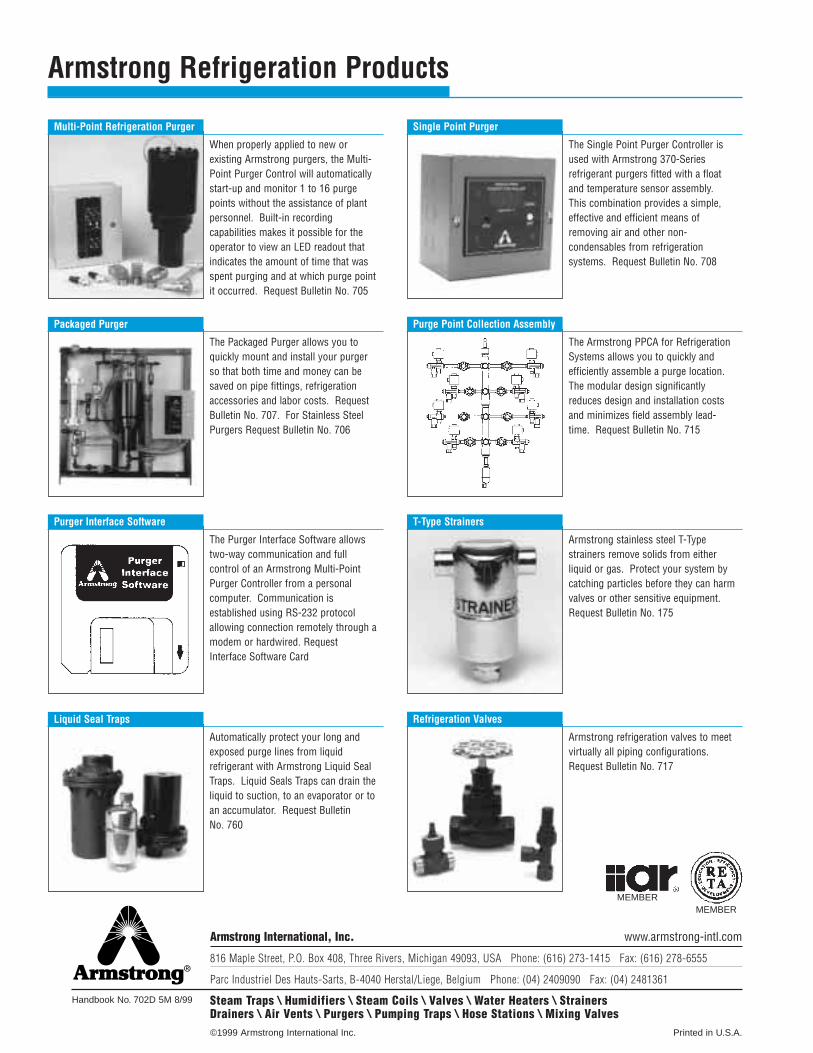
Liquid Seal Traps
Automatically protect your long andexposed purge lines from liquidrefrigerant with Armstrong Liquid SealTraps. Liquid Seals Traps can drain theliquid to suction, to an evaporator or toan accumulator. Request Bulletin No. 760
Multi-Point Refrigeration Purger
When properly applied to new orexisting Armstrong purgers, the Multi-Point Purger Control will automaticallystart-up and monitor 1 to 16 purgepoints without the assistance of plantpersonnel. Built-in recordingcapabilities makes it possible for theoperator to view an LED readout thatindicates the amount of time that wasspent purging and at which purge pointit occurred. Request Bulletin No. 705
Single Point Purger
The Single Point Purger Controller isused with Armstrong 370-Seriesrefrigerant purgers fitted with a floatand temperature sensor assembly.This combination provides a simple,effective and efficient means ofremoving air and other non-condensables from refrigerationsystems. Request Bulletin No. 708
Packaged Purger
The Packaged Purger allows you toquickly mount and install your purgerso that both time and money can besaved on pipe fittings, refrigerationaccessories and labor costs. RequestBulletin No. 707. For Stainless SteelPurgers Request Bulletin No. 706
Purge Point Collection Assembly
The Armstrong PPCA for RefrigerationSystems allows you to quickly andefficiently assemble a purge location.The modular design significantlyreduces design and installation costsand minimizes field assembly lead-time. Request Bulletin No. 715
Purger Interface Software
The Purger Interface Software allowstwo-way communication and fullcontrol of an Armstrong Multi-PointPurger Controller from a personalcomputer. Communication isestablished using RS-232 protocolallowing connection remotely through amodem or hardwired. RequestInterface Software Card
T-Type Strainers
Armstrong stainless steel T-Typestrainers remove solids from eitherliquid or gas. Protect your system bycatching particles before they can harmvalves or other sensitive equipment.Request Bulletin No. 175
Refrigeration Valves
Armstrong refrigeration valves to meetvirtually all piping configurations.Request Bulletin No. 717
Handbook No. 702D 5M 8/99
MEMBERMEMBER


