T T h h e e g g u u n n R R F F c c o o n n t t r r o o l l a a t t F F L L A A S S H H ( ( a a n n d d P P I I T T Z Z ) ) E E l l m m a a r r V V o o g g e e l l i i n n c c o o l l l l a a b b o o r r a a t t i i o o n n w w i i t t h h W W a a l l d d e e m m a a r r K K o o p p r r e e k k a a n n d d P P i i o o t t r r P P u u c c y y k k F F L L A A S S H H S S e e m m i i n n a a r r a a t t D D e e c c e e m m b b e e r r 1 1 9 9 t t h h 2 2 0 0 0 0 6 6
presented at FLASH seminar by E. Vogel, December 19th 2006
FLASH rf gun
• beam generated within the (1.3 GHz) RF gun by a laser
• filling time: typical 55 μs
• flat top time: up to 800 μs
• pulse repetition: up to 5 Hz
• high RF field: 40 MV/m
• FEL operation is sensitive to RF gun phase (0.5 deg)
• via the temperature the frequency is controlled (0.1 deg Celsius corresponds to 2.1 deg in RF phase)
The gun RF control at FLASH (and PITZ)
presented at FLASH seminar by E. Vogel, December 19th 2006
Rf gun control by SimCon 3.1 and some new algorithms Implications of missing probe: • calculation of probe form
forward and reflected rf • calibration is an issue
Algorithms: • P(I) control with recursive
20 kHz low-pass (IIR) for stability at ‘high’ gain (>5)
• Adaptive feed forward (AFF) from rf pulse to rf pulse
+
++
0
trackback+
+
AFFtable gate
reset
gun
∑virtual
rf probe
IIRlow-pass
FIR
klystronpre-amp
proportionalgain
integralgain AFF
gain
set pointtable
50M
Hz
1M
Hz
1
2
3
4
50MHz
1MHz
++
++
DAC
ADC
t
The gun RF control at FLASH (and PITZ)
presented at FLASH seminar by E. Vogel, December 19th 2006
first some theory …
The gun RF control at FLASH (and PITZ)
presented at FLASH seminar by E. Vogel, December 19th 2006
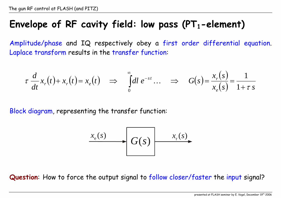
Envelope of RF cavity field: low pass (PT1-element)
Amplitude/phase and IQ respectively obey a first order differential equation. Laplace transform results in the transfer function:
( ) ( ) ( ) ( ) ( )( ) ssxsxsGedltxtxtx
tdd
e
rtserr τ
τ+
==⇒⇒=+ ∫∞
−
11
0
K
Block diagram, representing the transfer function:
)(sG)(e sx )(r sx
Question: How to force the output signal to follow closer/faster the input signal?
The gun RF control at FLASH (and PITZ)
presented at FLASH seminar by E. Vogel, December 19th 2006
Proportional control
Feeding back the error signal er xx −
)(e sx )(r sx)(sG
er xx −
increases the bandwidth
( ) ( ) ( ) ( ) ( )( )( ) ( ) ( ) ( )txtxtxtd
dg
txtxgtxtxtxtd
derrererr =+
+⇔−−=+
1ττ
response signal ( )txr follows quicker the stimulation signal ( )txe errors are suppressed by the factor g+1 .
The gun RF control at FLASH (and PITZ)
presented at FLASH seminar by E. Vogel, December 19th 2006
‘IQ’ instead of amplitude and phase
• quadrature (IQ) detection rather than dealing with amplitude and phase • phase calibration by rotation matrices • no manual phase adjustment needed!
reference RF signal
90º shiftedvrI t= cos( )ω vrQ t= sin( )ω
arbitrary RF signal
v =+ tAQ sin( )ω AI cos( )ω t
I/Qdemodulation
AQ
AI
(same frequency)vr
v
t
t
The gun RF control at FLASH (and PITZ)
presented at FLASH seminar by E. Vogel, December 19th 2006
(IQ) loop phase determination • non zero loop phase leads to an unwanted mixture of I and Q • applying a step function (I only) and recording the response (example for ∆f = 200 Hz)
excitation & response in time domain
response plotted in IQ plane
The gun RF control at FLASH (and PITZ)
presented at FLASH seminar by E. Vogel, December 19th 2006
Spiral like cavity response • the initial angle gives the loop phase • final IQ values for different tuning describe a circle • Alexander Brandts loop phase calibration methods are based on ‘circle fitting’
cavity response for loop phase zero
cavity response for loop phase 30º
Plots for the sc 1.3 GHz TESLA cavities, the RF gun behaves similar!
The gun RF control at FLASH (and PITZ)
presented at FLASH seminar by E. Vogel, December 19th 2006
Propagation time of signals (latency)
Signals require time to propagate through cables, …
… LLRF and high power RF.
Numbers for the FLASH RF gun: • 0.7 μs by cables klystron etc. • 0.15 μs by FPGA (ADC to DAC) • 0.35 μs by algorithm
The gun RF control at FLASH (and PITZ)
presented at FLASH seminar by E. Vogel, December 19th 2006
Latency restricts proportional gain and loop stability A time delay leads to an unwanted positive feedback for higher frequencies
0 time in arbitrary units
signal delay time
0 time in arbitrary units
signal delay time
ampl
itud
e in
arbi
trar
y un
its
ampl
itud
e in
arbi
trar
y un
its
negative feedback for low frequencies
positice feedback for high frequencies
feedbackis stable
feedbackis unstable
The gun RF control at FLASH (and PITZ)
presented at FLASH seminar by E. Vogel, December 19th 2006
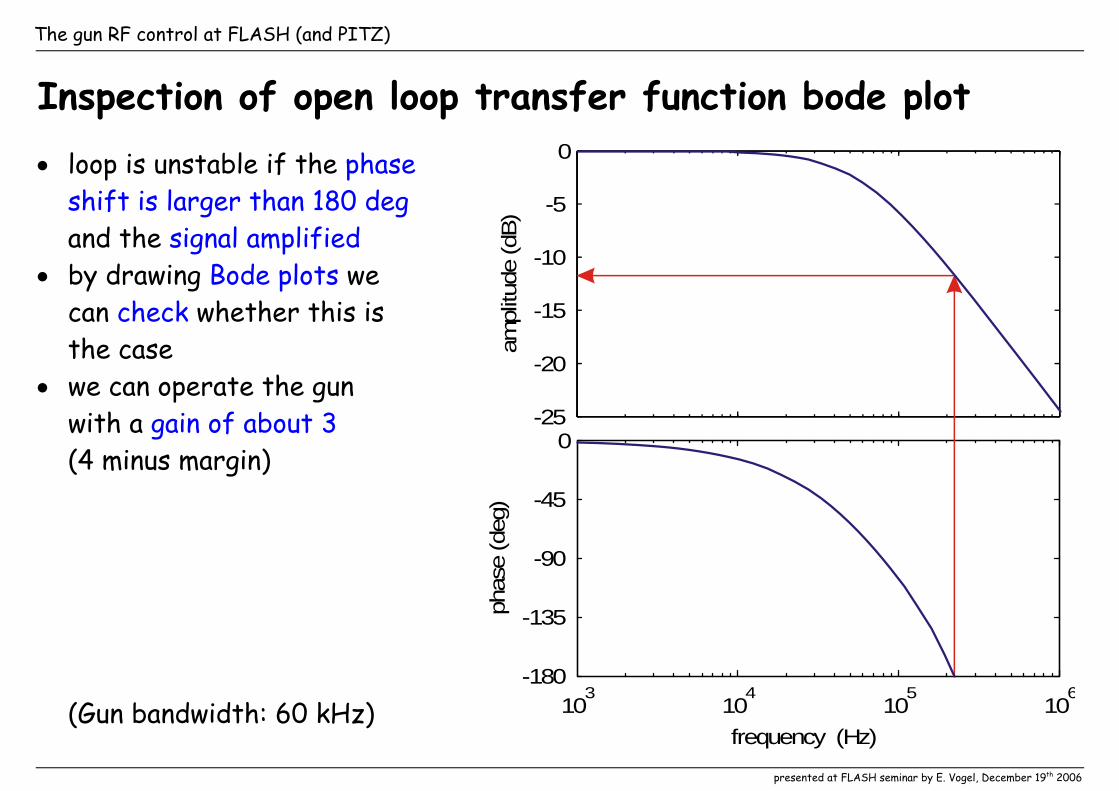
Inspection of open loop transfer function bode plot • loop is unstable if the phase
shift is larger than 180 deg and the signal amplified
• by drawing Bode plots we can check whether this is the case
• we can operate the gun with a gain of about 3 (4 minus margin)
(Gun bandwidth: 60 kHz)
-25
-20
-15
-10
-5
0
ampl
itude
(dB)
103
104
105
106
-180
-135
-90
-45
0
phas
e (d
eg)
frequency (Hz)
The gun RF control at FLASH (and PITZ)
presented at FLASH seminar by E. Vogel, December 19th 2006
Suppression of high frequencies
Suppression of high frequencies by
• the cavity bandwidth
• the restricted bandwidth of high power RF (e.g. klystron)
• and digital low pass filters in the LLRF.
)(e sx )(r sxcavityklystron
g
digitalfilter
latency(over all)
The gun RF control at FLASH (and PITZ)
presented at FLASH seminar by E. Vogel, December 19th 2006
Recursive or Infinite Impulse Response (IIR) filter
• IIRs are usually digital copies of analog filters • impulse response of an analog low pass is an exponential decay • to model this we reduce the output of a one step delay by
samp
3dB21f
fh π−≈
• and add it to the next input for the delay
)(e zx )(r zx1−z
h
The gun RF control at FLASH (and PITZ)
presented at FLASH seminar by E. Vogel, December 19th 2006
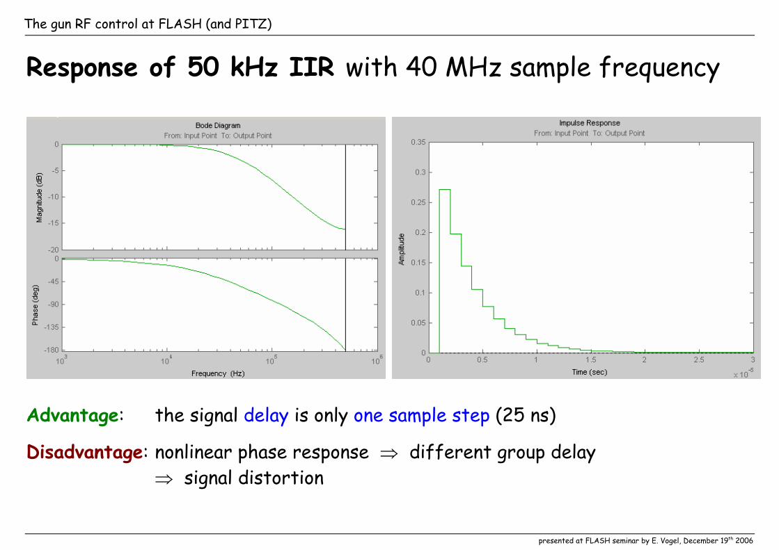
Response of 50 kHz IIR with 40 MHz sample frequency
Advantage: the signal delay is only one sample step (25 ns)
Disadvantage: nonlinear phase response ⇒ different group delay ⇒ signal distortion
The gun RF control at FLASH (and PITZ)
presented at FLASH seminar by E. Vogel, December 19th 2006
Concession to real life
• multiplication and sum can hardly performed together in FPGA
)(e zx )(r zx1−z
1−z
1−z
h
additional delays double reduction value
samp
3dB41f
fh π−≈
Bode diagram and the impulse response is similar to previous version
The gun RF control at FLASH (and PITZ)
presented at FLASH seminar by E. Vogel, December 19th 2006
Bode plot of ‘gun with 20 kHz IIR’ • with 20 kHz low pass we
can operate the gun with a gain of about 6 (8 minus margin)
-25
-20
-15
-10
-5
0
ampl
itude
(dB)
102
103
104
105
106
-180
-135
-90
-45
0
phas
e (d
eg)
frequency (Hz)
GunGun + IIR
The gun RF control at FLASH (and PITZ)
presented at FLASH seminar by E. Vogel, December 19th 2006
Confirmation by measurement
amplitude with proportional IQ control and gain larger 3
0 50 100 150 200
0
10
20
30
40
50 32 kHz low pass 20 kHz low pass
ampl
itude
in M
V/m
time in us
calibrationerror?
phase with proportional IQ control and gain larger 3
0 50 100 150 200
20
40
60
32 kHz low pass 20 kHz low pass
phas
e in
deg
time in us
Conclusion: an edge frequency of 20 kHz shall be used in practice
The gun RF control at FLASH (and PITZ)
presented at FLASH seminar by E. Vogel, December 19th 2006
Question:
How to get rid of
• systematic errors due to imperfect technical components?
• errors varying slower than the pulse repetition (drifts)?
Answer:
Using an adaptive feed forward (AFF).
The gun RF control at FLASH (and PITZ)
presented at FLASH seminar by E. Vogel, December 19th 2006
Main idea of adaptive feed forward algorithms
• each RF pulse shows similar errors
• transfer function of the ideal system is ‘well-known’
• calculate back the input signal for the ideal system leading to the error
• subtraction from the set point signal minimizes the error
Algorithms on the market use
• inverse system model from state space formalism • ‘tracking’ • ‘time reverse’ filtering
The gun RF control at FLASH (and PITZ)
presented at FLASH seminar by E. Vogel, December 19th 2006
Check of system (G) inversion by AFF algorithm:
application on ideal sys-tem (G) output cancels next output
feedforward
table
feedforwardalgorithm
first rfpulse
secondrf pulse
Gex rx
feedforward
table
Gex 0r =x
The gun RF control at FLASH (and PITZ)
presented at FLASH seminar by E. Vogel, December 19th 2006
Application of adaptive feed forward algorithm
application on ideal system (G) leads to unity transfer function for next pulse
first rfpulse
secondrf pulse
feedforward
table
Gex
feedforward
table
feedforwardalgorithm
Gex rx
er xx =
The gun RF control at FLASH (and PITZ)
presented at FLASH seminar by E. Vogel, December 19th 2006
A lean adaptive feed forward algorithm using ‘tracking’
• calculate next sample • difference is input signal driven
by the generator
‘free’ decaydriven by
generator
reconstructedgenerator signal
measures
• ideal tuning assumed • two subsequent I or Q samples used • cavity time constant τ
)(e zx
)(r zx1−z h1
h0
‘filter’ coefficients:
samp1samp
011 fhf
h ττ
=−= and
The gun RF control at FLASH (and PITZ)
presented at FLASH seminar by E. Vogel, December 19th 2006
to practice…
The gun RF control at FLASH (and PITZ)
presented at FLASH seminar by E. Vogel, December 19th 2006
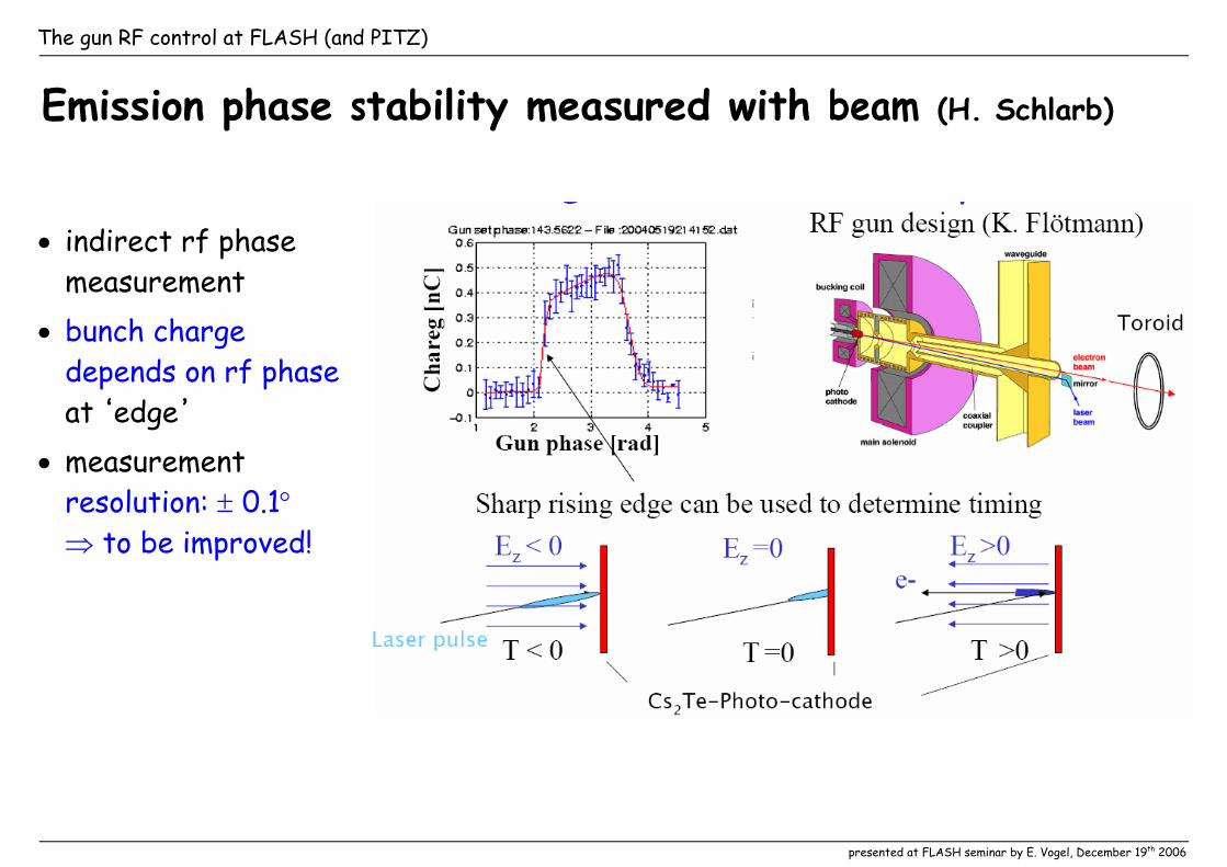
Emission phase stability measured with beam (H. Schlarb)
• indirect rf phase measurement
• bunch charge depends on rf phase at edge
• measurement resolution: ± 0.1° ⇒ to be improved!
The gun RF control at FLASH (and PITZ)
presented at FLASH seminar by E. Vogel, December 19th 2006
Bunch to bunch stability
RF drive only / similar to DSP
• resonance frequency change due to gun temperature change within pulse
• step caused by dark current kicker
PI control
• error suppression by about 5 (= gain)
The gun RF control at FLASH (and PITZ)
presented at FLASH seminar by E. Vogel, December 19th 2006
Bunch to bunch stability (continued)
PI control (repeated)
• error suppression by about 5 (= gain)
Alternating AFF and PI control
• gun temperature slope decreased by an other factor of 2
The gun RF control at FLASH (and PITZ)
presented at FLASH seminar by E. Vogel, December 19th 2006
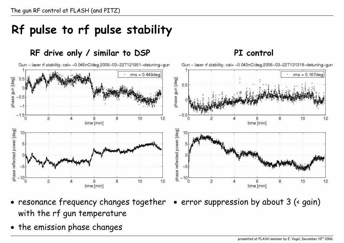
Rf pulse to rf pulse stability
RF drive only / similar to DSP
• resonance frequency changes together with the rf gun temperature
• the emission phase changes
PI control
• error suppression by about 3 (< gain)
The gun RF control at FLASH (and PITZ)
presented at FLASH seminar by E. Vogel, December 19th 2006
Rf pulse to rf pulse stability (continued)
AFF only
• error suppression by about 5 (= gain)
Alternating AFF and PI control
• gun temperature slope decreased by an other factor of 2
The gun RF control at FLASH (and PITZ)
presented at FLASH seminar by E. Vogel, December 19th 2006
Subsequent studies since spring 2006
In August 2006: • ‘improved’ toroid signals • slope on phase measured • first operation with 800 μs • SASE with 600 (800) bunches
In October 2006: • reflected power interlock due to
second circulator removed
In December 2006: • operation with 800 μs reestablished • slope on phase due to gun laser? • compensation of phase -> amplitude
nonlinearity within forward power implemented
In January 2007: • compensation of phase -> amplitude
nonlinearity within sensor part • hopefully ‘final’ measurements?
The gun RF control at FLASH (and PITZ)
presented at FLASH seminar by E. Vogel, December 19th 2006
Summary: gun rf control
Rf gun control with DSP: • insufficient processing power for vir-
tual probe (forward - reflected) • only forward power was regulated • field stability > 2°
< 0.5° required for SASE
Rf gun control with SimCon 3.1: • sufficient processing power for
virtual probe • sufficient processing power for
rf pulse to rf pulse AFF • field stability obtained: rms ~ 0.15°
fine for SASE at FLASH
What remains open?
Repetition of qualification measurements: • without dark current kicker and other