20
Issue 20 Visit our website www.dentsplymea.com The GuttaCore ™ System: Another Step Forward in the Evolution of Endodontics SDR ® The Ideal Material for Bulk-Fill in High C-Factor Cavities
Issue 20
Visit our website www.dentsplymea.com
The GuttaCore™ System:Another Step Forward in theEvolution of EndodonticsSDR®
The Ideal Material for Bulk-Fill inHigh C-Factor Cavities

Dynamics
Dynamics 3
pages
12-17Clinical Guidelines for the use of PROTAPERNEXT™ Instruments - Part 1
pages
18-19How Implant Prosthesis Design Influences ImplantMaintenance Access
DynamicsContentspages
4-5SDR® is the Ideal Material for Bulk-Fill in High C-Factor Cavities
pages
6-9The GuttaCore™ System: Another Step Forward in theEvolution of Endodontics
pages
10-11 Product News
The modern bulk filling technique using a suitable compositerestorative offers many advantages: a reliable marginal fit, lowpolymersiation shrinkage stress and avoidance of elaborateincremental layering—saving precious chair time and facilitatingmore cost-effective patient care. However, popular flowables andconventional composites are severely limited in terms ofachievable increment thickness—usually only 1–2mm.2 A realbreakthrough came in 2010, when DENTSPLY DeTreyintroduced SDR, a low-viscosity composite restorative speciallydesigned for the bulk-filling technique. This was the first materialthat allows reliable adaptation to the cavity wall with bulkincrements up to 4mm in thickness. The SDR base is thencovered with any methacrylate-based universal composite.
While conventional flowables can only be applied in small 1-2mmincrements due to their high polymerisation shrinkage stress,placement of up to 4mm increments is possible with SDR. Thisis because a ‘polymerisation modulator’ is chemically embeddedinto the polymerisable resin back bone providing the necessaryviscoelastic properties for low-stress polymerisation, which isconsiderably lower than in conventional composites. Thanks toSDR’s particularly high translucency, the polymerisation lightsafely penetrates all the way to the cavity bottom and initiatescontrolled polymerisation, even through 4mm increments.
Bulk-fill vs. incremental layering
The in-vitro study by Van Ende et al (2013), sets out to investigatethe extent to which conventional incremental layering can be
replaced by the simpler and time-saving bulk-filling technique,and which composites are suitable for this purpose. Anotherfocus of their experimental study was the shape of the cavity. Thetypical narrow and deep cavities in class I restorations, which aredifficult to reach for composite and curing light alike, wererepresented by appropriately prepared and classifiedexperimental groups.
Materials and methods
The study examined the adhesion of the restoratives to thecavity-floor dentin. For this purpose, standardised class Irestorations with different C-factors were restored with threedifferent composite restoratives: a bulk-fill flowable, (SDR,DENTSPLY) a flowable (G-aenial Universal Flo, GC3), and aconventional paste-like composite (Z100, 3M ESPE4). The nullhypothesis was neither the C-factor nor the restorative placementtechnique (incremental layering or bulk filling) had a significantinfluence on the micro tensile bond strength.
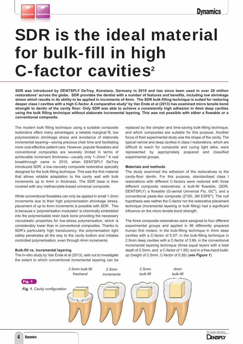
The three composite restoratives were assigned to four differentexperimental groups and applied in 96 differently preparedhuman first molars: in the bulk-filling technique in 4mm deepcavities with a C-factor of 5.57; in the bulk-filling technique in2.5mm deep cavities with a C-factor of 3.86, in the conventionalincremental layering technique (three equal layers with a totaldepth of 2.5mm, and a C-factor of 1.95); and in a free-hand build-up (height of 2.5mm, C-factor of 0.26) (see Figure 1).
SDR was introduced by DENTSPLY DeTrey, Konstanz, Germany in 2010 and has since been used in over 20 million
restorations1 across the globe. SDR provides the dentist with a number of features and benefits, including low shrinkage
stress which results in its ability to be applied in increments of 4mm. The SDR bulk-filling technique is suited for restoring
deeper class I cavities with a high C-factor. A comparative study2 by Van Ende et al (2013) has examined micro tensile bond
strength to dentin of the cavity floor: Only SDR was able to achieve a consistently high adhesion in 4mm deep cavities
using the bulk filling technique without elaborate incremental layering. This was not possible with either a flowable or a
conventional composite.
SDR is the ideal materialfor bulk-fill in high C-factor cavities2
2.5mm bulk-fillfreehand
2.5mmincrements
2.5mm bulk-fill
4mm bulk-fill
Fig. 1
Fig. 1. Cavity configuration.
Dynamics
Dynamics4
Dynamics
Dynamics 5
After one week of storage in water at 37°C, eight specimens pergroup with a standard cross-sectional area of 1mm2 wereproduced and examined for homogeneity and the presence of airbubbles at the matrices by light microscopy. Defective specimenswere excluded from the trial. Error-free specimens were stressedto failure in a micro tensile bond-strength test. The testing datawas evaluated statistically using the Kruskal-Wallis H-test,Weibull-analysis and Monte-Carlo-simulation.
Some samples with representative fractured surfaces wereprocessed for more in-depth analysis by scanning electronmicroscope (SEM) to obtain further information on the nature ofthe failures – whether they occurred in the preliminary stages ofthe micro tensile bond-strength test or after exceeding thefracture limit.
Results
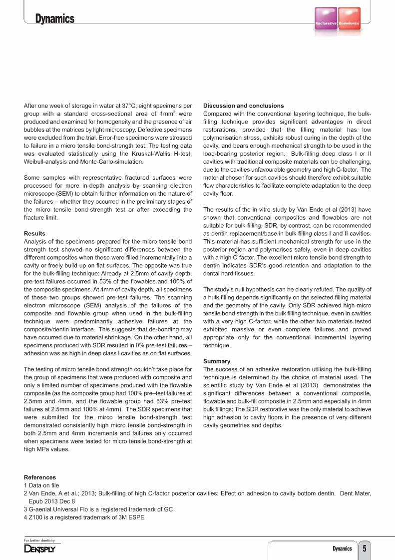
Analysis of the specimens prepared for the micro tensile bondstrength test showed no significant differences between thedifferent composites when these were filled incrementally into acavity or freely build-up on flat surfaces. The opposite was truefor the bulk-filling technique: Already at 2.5mm of cavity depth,pre-test failures occurred in 53% of the flowables and 100% ofthe composite specimens. At 4mm of cavity depth, all specimensof these two groups showed pre-test failures. The scanningelectron microscope (SEM) analysis of the failures of thecomposite and flowable group when used in the bulk-fillingtechnique were predominantly adhesive failures at thecomposite/dentin interface. This suggests that de-bonding mayhave occurred due to material shrinkage. On the other hand, allspecimens produced with SDR resulted in 0% pre-test failures –adhesion was as high in deep class I cavities as on flat surfaces.
The testing of micro tensile bond strength couldn’t take place forthe group of specimens that were produced with composite andonly a limited number of specimens produced with the flowablecomposite (as the composite group had 100% pre–test failures at2.5mm and 4mm, and the flowable group had 53% pre-testfailures at 2.5mm and 100% at 4mm). The SDR specimens thatwere submitted for the mirco tensile bond-strength testdemonstrated consistently high micro tensile bond-strength inboth 2.5mm and 4mm increments and failures only occurredwhen specimens were tested for micro tensile bond-strength athigh MPa values.
Discussion and conclusions
Compared with the conventional layering technique, the bulk-filling technique provides significant advantages in directrestorations, provided that the filling material has lowpolymerisation stress, exhibits robust curing in the depth of thecavity, and bears enough mechanical strength to be used in theload-bearing posterior region. Bulk-filling deep class I or IIcavities with traditional composite materials can be challenging,due to the cavities unfavourable geometry and high C-factor. Thematerial chosen for such cavities should therefore exhibit suitableflow characteristics to facilitate complete adaptation to the deepcavity floor.
The results of the in-vitro study by Van Ende et al (2013) haveshown that conventional composites and flowables are notsuitable for bulk-filling. SDR, by contrast, can be recommendedas dentin replacement/base in bulk-filling class I and II cavities.This material has sufficient mechanical strength for use in theposterior region and polymerises safely, even in deep cavitieswith a high C-factor. The excellent micro tensile bond strength todentin indicates SDR’s good retention and adaptation to thedental hard tissues.
The study’s null hypothesis can be clearly refuted. The quality ofa bulk filling depends significantly on the selected filling materialand the geometry of the cavity. Only SDR achieved high microtensile bond strength in the bulk filling technique, even in cavitieswith a very high C-factor, while the other two materials testedexhibited massive or even complete failures and provedappropriate only for the conventional incremental layeringtechnique.
Summary
The success of an adhesive restoration utilising the bulk-fillingtechnique is determined by the choice of material used. Thescientific study by Van Ende et al (2013) demonstrates thesignificant differences between a conventional composite,flowable and bulk-fill composite in 2.5mm and especially in 4mmbulk fillings: The SDR restorative was the only material to achievehigh adhesion to cavity floors in the presence of very differentcavity geometries and depths.
References
1 Data on file2 Van Ende, A et al.; 2013; Bulk-filling of high C-factor posterior cavities: Effect on adhesion to cavity bottom dentin. Dent Mater,
Epub 2013 Dec 83 G-aenial Universal Flo is a registered trademark of GC4 Z100 is a registered trademark of 3M ESPE
Dynamics6
Dynamics
Carrier Based Gutta-Percha: for or
against?
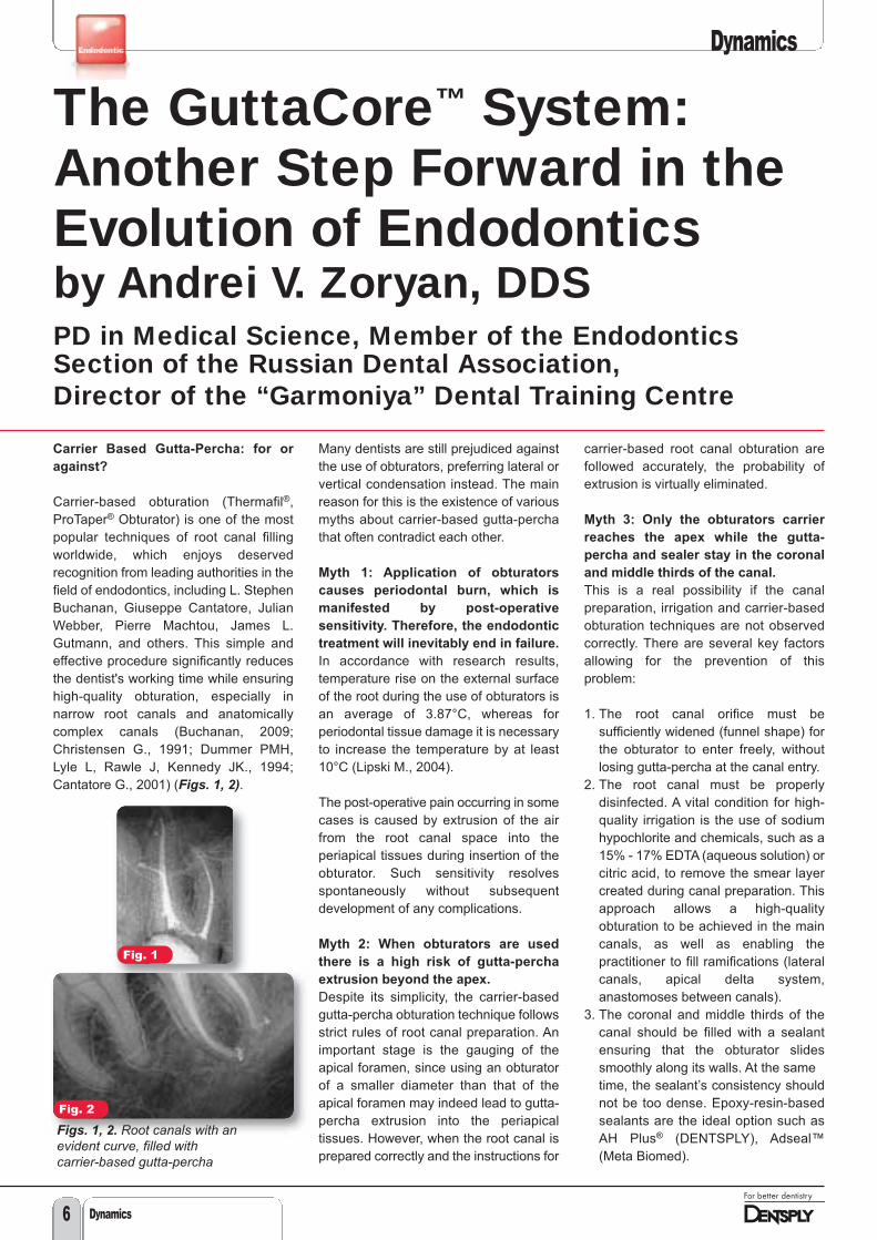
Carrier-based obturation (Thermafil®,ProTaper® Obturator) is one of the mostpopular techniques of root canal fillingworldwide, which enjoys deservedrecognition from leading authorities in thefield of endodontics, including L. StephenBuchanan, Giuseppe Cantatore, JulianWebber, Pierre Machtou, James L.Gutmann, and others. This simple andeffective procedure significantly reducesthe dentist's working time while ensuringhigh-quality obturation, especially innarrow root canals and anatomicallycomplex canals (Buchanan, 2009;Christensen G., 1991; Dummer PMH,Lyle L, Rawle J, Kennedy JK., 1994;Cantatore G., 2001) (Figs. 1, 2).
Many dentists are still prejudiced againstthe use of obturators, preferring lateral orvertical condensation instead. The mainreason for this is the existence of variousmyths about carrier-based gutta-perchathat often contradict each other.
Myth 1: Application of obturators
causes periodontal burn, which is
manifested by post-operative
sensitivity. Therefore, the endodontic
treatment will inevitably end in failure.
In accordance with research results,temperature rise on the external surfaceof the root during the use of obturators isan average of 3.87°C, whereas forperiodontal tissue damage it is necessaryto increase the temperature by at least10°C (Lipski M., 2004).
The post-operative pain occurring in somecases is caused by extrusion of the airfrom the root canal space into theperiapical tissues during insertion of theobturator. Such sensitivity resolvesspontaneously without subsequentdevelopment of any complications.
Myth 2: When obturators are used
there is a high risk of gutta-percha
extrusion beyond the apex.
Despite its simplicity, the carrier-basedgutta-percha obturation technique followsstrict rules of root canal preparation. Animportant stage is the gauging of theapical foramen, since using an obturatorof a smaller diameter than that of theapical foramen may indeed lead to gutta-percha extrusion into the periapicaltissues. However, when the root canal isprepared correctly and the instructions for
carrier-based root canal obturation arefollowed accurately, the probability ofextrusion is virtually eliminated.
Myth 3: Only the obturators carrier
reaches the apex while the gutta-
percha and sealer stay in the coronal
and middle thirds of the canal.
This is a real possibility if the canalpreparation, irrigation and carrier-basedobturation techniques are not observedcorrectly. There are several key factorsallowing for the prevention of thisproblem:
1. The root canal orifice must besufficiently widened (funnel shape) forthe obturator to enter freely, withoutlosing gutta-percha at the canal entry.
2. The root canal must be properlydisinfected. A vital condition for high-quality irrigation is the use of sodiumhypochlorite and chemicals, such as a15% - 17% EDTA (aqueous solution) orcitric acid, to remove the smear layercreated during canal preparation. Thisapproach allows a high-qualityobturation to be achieved in the maincanals, as well as enabling thepractitioner to fill ramifications (lateralcanals, apical delta system,anastomoses between canals).
3. The coronal and middle thirds of thecanal should be filled with a sealantensuring that the obturator slidessmoothly along its walls. At the sametime, the sealant’s consistency shouldnot be too dense. Epoxy-resin-basedsealants are the ideal option such asAH Plus® (DENTSPLY), Adseal™(Meta Biomed).
Fig. 1
Fig. 2
The GuttaCore™ System:Another Step Forward in theEvolution of Endodonticsby Andrei V. Zoryan, DDSPD in Medical Science, Member of the EndodonticsSection of the Russian Dental Association, Director of the “Garmoniya” Dental Training Centre
Figs. 1, 2. Root canals with anevident curve, filled with carrier-based gutta-percha
Dynamics
Dynamics 7
4. The obturator must be inserted into theroot canal slowly and smoothly.Thermafil® obturators, with a .04 taper,are inserted into the canal over a periodof 3 to 4 seconds. Obturators with alarger taper (ProTaper andWaveOne™) are inserted over a periodof 6 to 8 seconds.
Using carrier-based gutta-percha allowspredictable and successful results to beachieved in root canal obturation, asconfirmed by numerous studies (Beatty etal., 1989; Dummer et al., 1993; Gençogluet al., 1993; Gençoglu et al., 2002; Xu etal., 2007; Inan et al., 2007; Gençoglu etal., 2007; Saunders et al., 1994; Gutmannet al., 1993; Dalat et al., 1994;Pathomvanich et al., 1996; Abarca et al.,2001; Kontakiotis et al., 2007)
Myth 4: It is difficult to remove
obturators from the canal at retreatment.
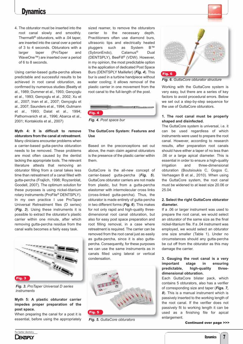
Many clinicians encounter problems whena carrier-based gutta-percha obturationneeds to be removed. These problemsare most often caused by the dentistlacking the appropriate tools. The relevantliterature attests that removing anobturator filling from a canal takes lesstime than retreatment of a canal filled withgutta-percha (Frajlich, 1998; Royzenblat,Goodell, 2007). The optimum solution forthese purposes is using nickel-titaniumrotary instruments (ProFile® DENTSPLY).In my own practice I use ProTaperUniversal Retreatment files (D series)(Fig. 3). Using these instruments it ispossible to extract the obturator’s plasticcarrier within one minute, after whichremoving gutta-percha residue from thecanal walls becomes a fairly easy task.
Myth 5: A plastic obturator carrier
impedes proper preparation of the
post space.
When preparing the canal for a post it isessential, before using the appropriately
sized reamer, to remove the obturatorscarrier to the necessary depth.Practitioners often use diamond burs,ultrasonic tips and electrically heatedpluggers such as System B™(SybronEndo), Calamus® Dual(DENTSPLY), BeeFill® (VDW). However,in my opinion, the most predictable optionis the application of dedicated Post SpaceBurs (DENTSPLY Maillefer) (Fig. 4). Thisbur is used in a turbine handpiece withoutwater cooling; it allows removal of theplastic carrier in one movement from theroot canal to the full-length of the post.
The GuttaCore System: Features and
Use
Based on the preconceptions set outabove, the main claim against obturatorsis the presence of the plastic carrier withinthem.
GuttaCore is the all-new concept ofcarrier-based gutta-percha (Fig. 5).GuttaCore obturator carriers are not madefrom plastic, but from a gutta-perchaelastomer with intermolecular cross links(cross-linked gutta-percha). Thus, theobturator is made entirely of gutta-perchain two different forms (Fig. 6). This makesfor not only rapid and high-quality three-dimensional root canal obturation, butalso for easy post space preparation androot filling removal, in a case whereretreatment is required. The carrier can beremoved from the root canal just as easilyas gutta-percha, since it is also gutta-percha. Consequently, for these purposeswe can use the same instruments as incanals filled using lateral or verticalcondensation.
Working with the GuttaCore system isvery easy, but there are a series of keyfactors to avoid procedural errors. Belowwe set out a step-by-step sequence forthe use of GuttaCore obturators.
1. The root canal must be properly
shaped and disinfected.
The GuttaCore system is universal, i.e. itcan be used regardless of whichinstruments were used to prepare the rootcanal. However, according to researchresults, after preparation root canalsshould have either a taper of no less than.06 or a large apical diameter. This isessential in order to ensure a high-qualityirrigation and three-dimensionalobturation (Boutsioukis C, Gogos C,Verhaagen B et al., 2010). When usingthe GuttaCore system, the root canalmust be widened to at least size 20.06 or25.04.
2. Select the right GuttaCore obturator
diameter.
If a .06 or larger instrument was used toprepare the root canal, we would selectan obturator of the same size as the finalnickel-titanium file. If a .04 instrument wasemployed, we would select an obturatorone size smaller (Table 1). Under nocircumstances should any gutta-perchabe cut off from the obturator as this maydamage the carrier.
3. Gauging the root canal is a very
important stage in ensuring
predictable, high-quality three-
dimensional obturation.
Each GuttaCore blister pack, whichcontains 5 obturators, also has a verifierof corresponding size and taper (Figs. 7,8). This is a manual instrument which ispassively inserted to the working length ofthe root canal. If the verifier does notpassively fit to working length it can beused as a finishing file for apicalenlargement.
Fig. 3
Fig. 3. ProTaper Universal D seriesinstruments
Fig. 5
Fig. 5. GuttaCore obturators
Fig. 6
Fig. 6. GuttaCore obturator structure
Fig. 4
Fig. 4. Post space bur
Continued over page >>>
Dynamics
Dynamics8
<<<<Continued from previous page
4. When using GuttaCore obturators, a
thin layer of sealant is applied into the
coronal, or in case of long root canals,
the coronal and middle thirds of the
canal.
To apply the sealant we would employ apaper point, a probe or, in the case ofusing AH Plus® Jet™ sealant, a specialmixing tip (Fig. 9). The pre-heatedobturator, in the process of insertion intothe root canal, evenly distributes thesealant along its walls. If there is excesssealant or it was applied to the full workinglength, there is a very high risk of sealantextrusion into the periapical tissues.
5. The working length is set on the
obturator, after which it is placed into a
holder of one of the ThermaPrep® 2
oven’s heating elements (Figs. 10, 11).
The distinguishing characteristics of theThermaPrep 2 oven are rapid three-dimensional heating of obturators, whilemaintaining the properties of the gutta-percha carrier, as well as the option ofhaving both heating elements operatingsimultaneously. When working with the
GuttaCore system, unlike obturators witha plastic carrier, a minimum heating levelof 20-25 is set on the oven operatingpanel, regardless of the obturator size(Fig. 12).
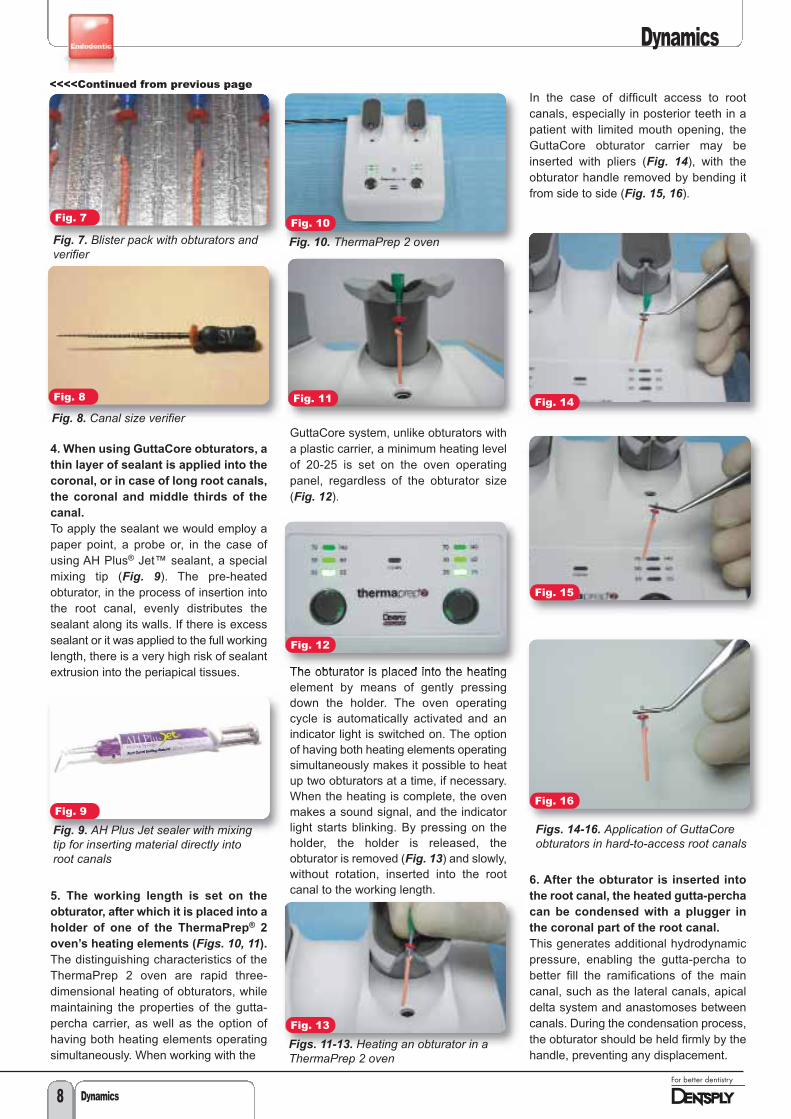
The obturator is placed into the heatingelement by means of gently pressingdown the holder. The oven operatingcycle is automatically activated and anindicator light is switched on. The optionof having both heating elements operatingsimultaneously makes it possible to heatup two obturators at a time, if necessary.When the heating is complete, the ovenmakes a sound signal, and the indicatorlight starts blinking. By pressing on theholder, the holder is released, theobturator is removed (Fig. 13) and slowly,without rotation, inserted into the rootcanal to the working length.
In the case of difficult access to rootcanals, especially in posterior teeth in apatient with limited mouth opening, theGuttaCore obturator carrier may beinserted with pliers (Fig. 14), with theobturator handle removed by bending itfrom side to side (Fig. 15, 16).
6. After the obturator is inserted into
the root canal, the heated gutta-percha
can be condensed with a plugger in
the coronal part of the root canal.
This generates additional hydrodynamicpressure, enabling the gutta-percha tobetter fill the ramifications of the maincanal, such as the lateral canals, apicaldelta system and anastomoses betweencanals. During the condensation process,the obturator should be held firmly by thehandle, preventing any displacement.
Fig. 7
Fig. 7. Blister pack with obturators andverifier
Fig. 8
Fig. 8. Canal size verifier
Fig. 9
Fig. 9. AH Plus Jet sealer with mixingtip for inserting material directly intoroot canals
Fig. 10
Fig. 10. ThermaPrep 2 oven
Fig. 11
Fig. 12
Fig. 13
Figs. 11-13. Heating an obturator in aThermaPrep 2 oven
Fig. 14
Fig. 15
Fig. 16
Figs. 14-16. Application of GuttaCoreobturators in hard-to-access root canals
Dynamics
Dynamics 9
7. The final stage of obturation is theremoval of the handle and the excesscarrier above the orifice level. When using the GuttaCore system thereis no need to use a Therma-Cut bur forthis purpose. We can either cut off thecarrier at the orifice using a regular roundbur or sharp hand excavator, or simplybreak it off using gentle lateral motions. Toclean the gutta-percha and sealantresidue from the tooth cavity, we can usea cotton ball soaked in chloroform orethanol. To clean the gutta-percha andsealant
Conclusion
Endodontics is evolving along the lines ofsimplifying the technical part ofprocedures and reducing the dentist'swork time needed to perform them. Thereare new instruments, materials, devicesand accessories being developed in orderto reduce the number of working stagesand make endodontic treatment lesslabour-intensive. At the same time, greatattention must certainly be paid to ensurea simultaneous increase in thepredictability of results and overalltreatment success.
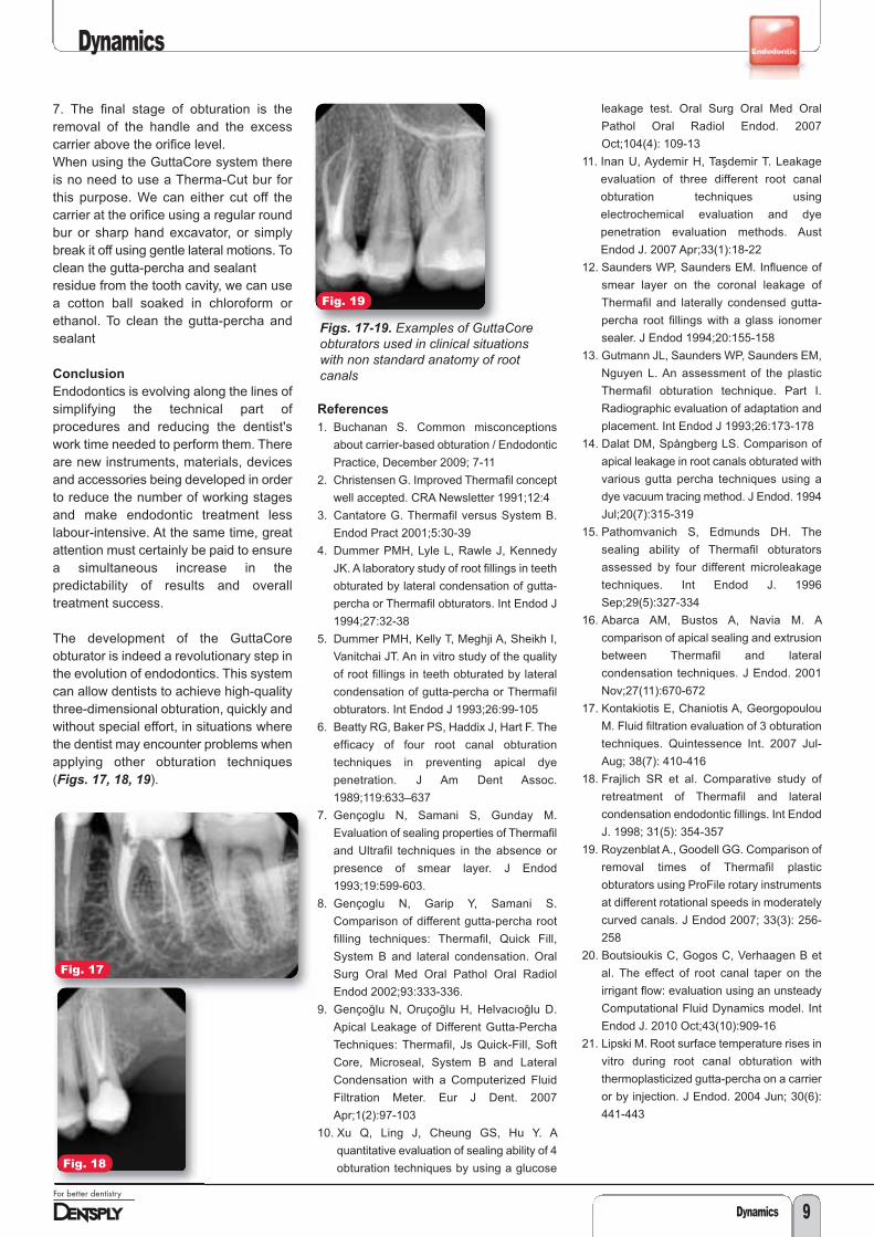
The development of the GuttaCoreobturator is indeed a revolutionary step inthe evolution of endodontics. This systemcan allow dentists to achieve high-qualitythree-dimensional obturation, quickly andwithout special effort, in situations wherethe dentist may encounter problems whenapplying other obturation techniques(Figs. 17, 18, 19).
References
1. Buchanan S. Common misconceptions
about carrier-based obturation / Endodontic
Practice, December 2009; 7-11
2. Christensen G. Improved Thermafil concept
well accepted. CRA Newsletter 1991;12:4
3. Cantatore G. Thermafil versus System B.
Endod Pract 2001;5:30-39
4. Dummer PMH, Lyle L, Rawle J, Kennedy
JK. A laboratory study of root fillings in teeth
obturated by lateral condensation of gutta-
percha or Thermafil obturators. Int Endod J
1994;27:32-38
5. Dummer PMH, Kelly T, Meghji A, Sheikh I,
Vanitchai JT. An in vitro study of the quality
of root fillings in teeth obturated by lateral
condensation of gutta-percha or Thermafil
obturators. Int Endod J 1993;26:99-105
6. Beatty RG, Baker PS, Haddix J, Hart F. The
efficacy of four root canal obturation
techniques in preventing apical dye
penetration. J Am Dent Assoc.
1989;119:633–637
7. Gençoglu N, Samani S, Gunday M.
Evaluation of sealing properties of Thermafil
and Ultrafil techniques in the absence or
presence of smear layer. J Endod
1993;19:599-603.
8. Gençoglu N, Garip Y, Samani S.
Comparison of different gutta-percha root
filling techniques: Thermafil, Quick Fill,
System B and lateral condensation. Oral
Surg Oral Med Oral Pathol Oral Radiol
Endod 2002;93:333-336.
9. Gençoḡlu N, Oruçoḡlu H, Helvacıoḡlu D.
Apical Leakage of Different Gutta-Percha
Techniques: Thermafil, Js Quick-Fill, Soft
Core, Microseal, System B and Lateral
Condensation with a Computerized Fluid
Filtration Meter. Eur J Dent. 2007
Apr;1(2):97-103
10. Xu Q, Ling J, Cheung GS, Hu Y. A
quantitative evaluation of sealing ability of 4
obturation techniques by using a glucose
leakage test. Oral Surg Oral Med Oral
Pathol Oral Radiol Endod. 2007
Oct;104(4): 109-13
11. Inan U, Aydemir H, Taşdemir T. Leakage
evaluation of three different root canal
obturation techniques using
electrochemical evaluation and dye
penetration evaluation methods. Aust
Endod J. 2007 Apr;33(1):18-22
12. Saunders WP, Saunders EM. Influence of
smear layer on the coronal leakage of
Thermafil and laterally condensed gutta-
percha root fillings with a glass ionomer
sealer. J Endod 1994;20:155-158
13. Gutmann JL, Saunders WP, Saunders EM,
Nguyen L. An assessment of the plastic
Thermafil obturation technique. Part I.
Radiographic evaluation of adaptation and
placement. Int Endod J 1993;26:173-178
14. Dalat DM, Spångberg LS. Comparison of
apical leakage in root canals obturated with
various gutta percha techniques using a
dye vacuum tracing method. J Endod. 1994
Jul;20(7):315-319
15. Pathomvanich S, Edmunds DH. The
sealing ability of Thermafil obturators
assessed by four different microleakage
techniques. Int Endod J. 1996
Sep;29(5):327-334
16. Abarca AM, Bustos A, Navia M. A
comparison of apical sealing and extrusion
between Thermafil and lateral
condensation techniques. J Endod. 2001
Nov;27(11):670-672
17. Kontakiotis E, Chaniotis A, Georgopoulou
M. Fluid filtration evaluation of 3 obturation
techniques. Quintessence Int. 2007 Jul-
Aug; 38(7): 410-416
18. Frajlich SR et al. Comparative study of
retreatment of Thermafil and lateral
condensation endodontic fillings. Int Endod
J. 1998; 31(5): 354-357
19. Royzenblat A., Goodell GG. Comparison of
removal times of Thermafil plastic
obturators using ProFile rotary instruments
at different rotational speeds in moderately
curved canals. J Endod 2007; 33(3): 256-
258
20. Boutsioukis C, Gogos C, Verhaagen B et
al. The effect of root canal taper on the
irrigant flow: evaluation using an unsteady
Computational Fluid Dynamics model. Int
Endod J. 2010 Oct;43(10):909-16
21. Lipski M. Root surface temperature rises in
vitro during root canal obturation with
thermoplasticized gutta-percha on a carrier
or by injection. J Endod. 2004 Jun; 30(6):
441-443
Fig. 17
Fig. 18
Fig. 19
Figs. 17-19. Examples of GuttaCoreobturators used in clinical situationswith non standard anatomy of rootcanals

Dynamics
Dynamics10
PRODUCT NEWSfrom DENTSPLY
DENTSPLY is proud to announce new
contemporary composite packaging.
DENTSPLY strive to make products that keep up with the times inaddition to being safe and simple to use. As a consequence, DENTSPLYis pleased to announce a packaging redesign for CeramX® mono+,CeramX duo+, Spectrum® TPH3®, Dyract® XP, QuiXfil® and X-Flow®
syringe and compule items. The outer cartons of both the syringe andcompule items are to be replaced with fresh looking, space savingpouches. The new outer packaging offers protection against moistureand helps to prevent product counterfeiting. In addition to the changesin the outer packaging, all syringes have been updated, they will not onlylook more modern in shape, design and feature laser marked labels butthey will also be more ergonomic to use. Their innovative laser markingwill ensure that the labelling remains readable even after several roundsof wipe disinfection.
The new packaging will be available over a phased timeline from May2014 to July 2014. Please refer to www.dentsplymea.com or your localDENTSPLY representative for more information.
AH Plus® receives top ratings from ecological
consumer magazine.
The DENTSPLY DeTrey root canal sealing material, AH Plus hasreceived top ratings for exceptional biocompatibility in comparative trials1
conducted by Germany’s ecological consumer magazine, ÖKO-TEST.Furthermore, a benefit versus risk assessment was conducted and AHPlus received the highest rating of “very good.” The highly rated productswere identified by features such as “remaining practically unabsorbed bythe body, are well tolerated by the tissue, and exhibit no adverse effects1”.Out of the highly rated products, AH Plus was identified as the BEST ofthe sealers category and was considered as a state of the art adhesivefilling material, characterised by a unique polyaddition reaction that formsneither an allergenic formaldehyde nor uses the hormonally activebisphenol-A.
1 ÖKO-TEST 10/2013, pp. 102–109.

DENTSPLY celebrated as PROTAPER NEXT™claimed the “Excellence in clinical equipment”Award at the AEEDC exhibition, Dubai 2014.
The Award commemorates dental products whichare revolutionary in professional care or are groundbreaking developments to existing products.
PROTAPER NEXT was declared the winner due tothe innovation it brings to the DENTSPLY MailleferPROTAPER system, which has been the goldstandard in endodontics for many years.
PROTAPER NEXT features the same variable taperdesign that clinicians have turned to for more than adecade, but has been refined to offer a shorterclinical sequence; requiring just two files for themajority of cases, greater flexibility and a uniquepatented design for improved performance and fully-tapered, predictable shaping.
Key features include:
• One torque setting, one speed setting and only two files per treatment forthe majority of cases
• Swaggering action that reduces binding and improves debris removal
• Patented off-centre rectangular cross-section for greater strength andmore space for debris removal
• M-Wire® NiTi alloy for increased flexibility and resistance to cyclic fatigue
• Faster shaping
• Single-use and pre-sterilised
PROTAPER NEXT is a complete system solution for all the steps of theendodontic procedure, contact us now at www.dentsplymea.com to see foryourself how the Award winning PROTAPER NEXT system canrevolutionise your endodontic procedures.
Genios® teeth are German designed and engineered andtherefore bear the mark of quality and precision. Their uniquepatented interdental closures ensure harmonious connectionswith anterior adjacent teeth, eliminating black interdentalspaces and ensuring natural-looking papillae.
Key features:
• Five distinct design zones including cervical, neck, body,enamel and mamelons for life-like aesthetics
• 9 anterior upper & 6 anterior lower moulds, 9 posterior upper& lower moulds with 33º cuspation
• Available in 16 V-shades
• A unique interpenetrated polymer network (INPEN) structurefor strength and durability
Genios teeth are complimented by Eclipse® light cure resindenture system and Lucitone 199® denture acrylic fortraditional heat cure dentures.
Dynamics
Dynamics 11
PROTAPER NEXT™ wins
“Excellence in clinical
equipment” Award.
Introduction
According to Bird, Chambers and Peters(2009), rotary nickel titanium instrumentshave become a standard tool for shapingroot canal systems. These instrumentsprovide the clinician with severaladvantages compared to conventionalstainless steel instruments. For instance,they are more flexible, have increasedcutting efficiency (Kim et al, 2012; Peters,2004; Walia, Brantley, Gerstein, 1988),can create centred preparations morerapidly (Short, Morgan, Baumgartner,1997; Glossen et al, 1995) and canproduce tapered root canal preparationswith a reduced tendency of canaltransportation (Chen, Messer, 2002; Kimet al, 2012).
However, nickel titanium instrumentsappear to have a high risk of fracture(Arens et al, 2003; Sattapan et al, 2000)mainly because of flexural and torsionalstresses during rotation in the root canalsystem (Berutti et al, 2003; Parashos,Messer, 2006).
When there is a wide area of contactbetween the cutting edge of theinstrument and the canal wall duringrotation, the instrument will be subjectedto an increase in torsional stress (Blum etal, 1999). The preparation of areproducible glide path can reduce thetorsional stress on root canal instruments.A glide path is a smooth passage thatextends from the canal orifice in the pulpchamber to its opening at the apex of theroot (West, 2006). This will provide acontinuous, uninterrupted pathway for therotary nickel titanium instrument to enterand to move freely to the root canalterminus.
The main purpose of a glide path is tocreate a root canal diameter the samesize as, or ideally a size bigger than, thefirst rotary instrument introduced (Beruttiet al, 2004; Varela-patino et al, 2005;Berutti et al, 2009).
Another way to reduce torsional stress isto incorporate multiple progressive tapersto the instrument design for example the
Protaper® Universal system (DENTSPLY/Maillefer). According to West (2001), theprogressive taper allows for only smallareas of dentine to be engaged. Thisdesign concept also contributes tomaintaining the original canal curvature(Yun, Kim, 2003).
PROTAPER NEXT
The PROTAPER NEXT system wasrecently launched into the dental market.There are five instruments in the systembut most canals can be prepared by usingonly the first two.
This system also makes use of themultiple progressive taper concept. Eachfile presents with an increasing anddecreasing percentage tapered design ona single file concept (Ruddle, Machtou,West, 2013). The design ensures thatthere is reduced contact between thecutting flutes of the instrument and thedentine wall, thus reducing the chance fortaper lock (screw-in effect). At the sametime, it also increases flexibility andcutting efficiency (Ruddle, 2001).
Peet J van der Vyver is an extraordinary professor at the Department of Odontology, School of Dentistry, University of
Pretoria and Private Practice, Sandton, South Africa (see www.studio4endo.com for more).
Michael J Scianamblo DDS is an endodontist and the developer of Critical Path Technology. He is a postgraduate and fellow
of the Harvard School of Dental Medicine and has served as a faculty member of the University of the Pacific and the
University of California, Schools of Dentistry in San Francisco.
Clinical guidelines for theuse of PROTAPER NEXT™
instruments: part onePeet J van der Vyver and Michael JScianamblo discuss the clinical guidelinesfor using PROTAPER NEXT instrumentsThis article has been reprinted with kind permissionfrom Endodontic Practice 16(4): 33-40.
Dynamics
Dynamics12
..
Dynamics 13
Dynamics
The first instrument in the system isPROTAPER NEXT X1 (Figure 1), with atip size of 0.17mm and a 4% taper. Thisinstrument is used after creation of areproducible glide path by means of handinstruments or rotary Pathfiles™. Thisinstrument is always followed by thesecond instrument, the PROTAPERNEXT X2 (0.25mm tip and 6% taper)(Figure 2). PROTAPER NEXT X2 can beregarded as the first finishing file in thesystem, as it leaves the prepared rootcanal with adequate shape and taper foroptimal irrigation and root canalobturation. PROTAPER NEXT X1 and X2have an increasing and decreasingpercentage tapered design over the activeportion of the instruments.
The last three finishing instruments arePROTAPER NEXT X3 (0.30mm tip with7% taper) (Figure 3), PROTAPER NEXTX4 (0.40mm tip with 6% taper) (Figure 4)and PROTAPER NEXT X5 (0.50mm tipwith 6% taper) (Figure 5). Theseinstruments have a decreasingpercentage taper from the tip to theshank. PROTAPER NEXT X3, X4 and X5can be used to either create more taper ina root canal or to prepare larger root canalsystems.
Another benefit of this system is the factthat the instruments are manufacturedfrom M-wire® and not traditional nickel
titanium alloy. Research by Johnson et al(2008) demonstrated that the M-wire alloycould reduce cyclic fatigue by 400%compared to similar instrumentsmanufactured from conventional nickeltitanium alloys. The added metallurgicalbenefit contributes towards more flexibleinstruments, increased safety andprotection against instrument fracture(Gutmann, Gao, 2012).
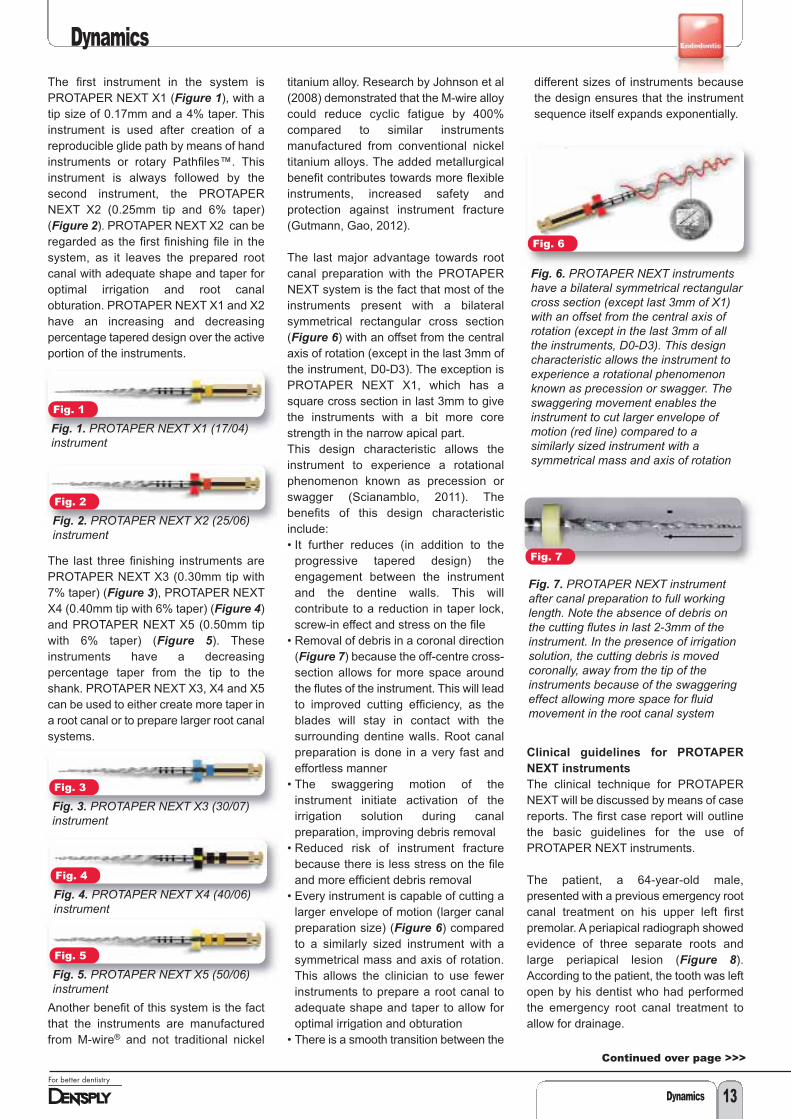
The last major advantage towards rootcanal preparation with the PROTAPERNEXT system is the fact that most of theinstruments present with a bilateralsymmetrical rectangular cross section(Figure 6) with an offset from the centralaxis of rotation (except in the last 3mm ofthe instrument, D0-D3). The exception isPROTAPER NEXT X1, which has asquare cross section in last 3mm to givethe instruments with a bit more corestrength in the narrow apical part. This design characteristic allows theinstrument to experience a rotationalphenomenon known as precession orswagger (Scianamblo, 2011). Thebenefits of this design characteristicinclude: • It further reduces (in addition to the
progressive tapered design) theengagement between the instrumentand the dentine walls. This willcontribute to a reduction in taper lock,screw-in effect and stress on the file
• Removal of debris in a coronal direction(Figure 7) because the off-centre cross-section allows for more space aroundthe flutes of the instrument. This will leadto improved cutting efficiency, as theblades will stay in contact with thesurrounding dentine walls. Root canalpreparation is done in a very fast andeffortless manner
• The swaggering motion of theinstrument initiate activation of theirrigation solution during canalpreparation, improving debris removal
• Reduced risk of instrument fracturebecause there is less stress on the fileand more efficient debris removal
• Every instrument is capable of cutting alarger envelope of motion (larger canalpreparation size) (Figure 6) comparedto a similarly sized instrument with asymmetrical mass and axis of rotation.This allows the clinician to use fewerinstruments to prepare a root canal toadequate shape and taper to allow foroptimal irrigation and obturation
• There is a smooth transition between the
different sizes of instruments becausethe design ensures that the instrumentsequence itself expands exponentially.
Clinical guidelines for PROTAPER
NEXT instruments
The clinical technique for PROTAPERNEXT will be discussed by means of casereports. The first case report will outlinethe basic guidelines for the use ofPROTAPER NEXT instruments.
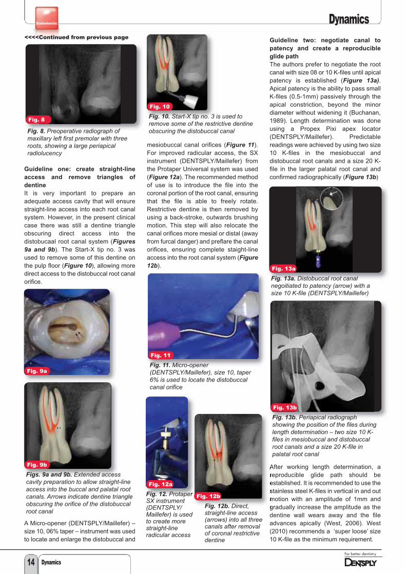
The patient, a 64-year-old male,presented with a previous emergency rootcanal treatment on his upper left firstpremolar. A periapical radiograph showedevidence of three separate roots andlarge periapical lesion (Figure 8).According to the patient, the tooth was leftopen by his dentist who had performedthe emergency root canal treatment toallow for drainage.
Fig. 1
Fig. 1. PROTAPER NEXT X1 (17/04)instrument
Fig. 7
Fig. 7. PROTAPER NEXT instrumentafter canal preparation to full workinglength. Note the absence of debris onthe cutting flutes in last 2-3mm of theinstrument. In the presence of irrigationsolution, the cutting debris is movedcoronally, away from the tip of theinstruments because of the swaggeringeffect allowing more space for fluidmovement in the root canal system
Fig. 6
Fig. 6. PROTAPER NEXT instrumentshave a bilateral symmetrical rectangularcross section (except last 3mm of X1)with an offset from the central axis ofrotation (except in the last 3mm of allthe instruments, D0-D3). This designcharacteristic allows the instrument toexperience a rotational phenomenonknown as precession or swagger. Theswaggering movement enables theinstrument to cut larger envelope ofmotion (red line) compared to asimilarly sized instrument with asymmetrical mass and axis of rotation
Fig. 2
Fig. 2. PROTAPER NEXT X2 (25/06)instrument
Fig. 3
Fig. 3. PROTAPER NEXT X3 (30/07)instrument
Fig. 4
Fig. 4. PROTAPER NEXT X4 (40/06)instrument
Fig. 5
Fig. 5. PROTAPER NEXT X5 (50/06)instrument
Continued over page >>>
Guideline one: create straight-line
access and remove triangles of
dentine
It is very important to prepare anadequate access cavity that will ensurestraight-line access into each root canalsystem. However, in the present clinicalcase there was still a dentine triangleobscuring direct access into thedistobucaal root canal system (Figures9a and 9b). The Start-X tip no. 3 wasused to remove some of this dentine onthe pulp floor (Figure 10), allowing moredirect access to the distobuccal root canalorifice.
A Micro-opener (DENTSPLY/Maillefer) –size 10, 06% taper – instrument was usedto locate and enlarge the distobuccal and
mesiobuccal canal orifices (Figure 11).For improved radicular access, the SXinstrument (DENTSPLY/Maillefer) fromthe Protaper Universal system was used(Figure 12a). The recommended methodof use is to introduce the file into thecoronal portion of the root canal, ensuringthat the file is able to freely rotate.Restrictive dentine is then removed byusing a back-stroke, outwards brushingmotion. This step will also relocate thecanal orifices more mesial or distal (awayfrom furcal danger) and preflare the canalorifices, ensuring complete staight-lineaccess into the root canal system (Figure12b).
Guideline two: negotiate canal to
patency and create a reproducible
glide path
The authors prefer to negotiate the rootcanal with size 08 or 10 K-files until apicalpatency is established (Figure 13a).Apical patency is the ability to pass smallK-files (0.5-1mm) passively through theapical constriction, beyond the minordiameter without widening it (Buchanan,1989). Length determination was doneusing a Propex Pixi apex locator(DENTSPLY/Maillefer). Predictablereadings were achieved by using two size10 K-files in the mesiobuccal anddistobuccal root canals and a size 20 K-file in the larger palatal root canal andconfirmed radiographically (Figure 13b)
After working length determination, areproducible glide path should beestablished. It is recommended to use thestainless steel K-files in vertical in and outmotion with an amplitude of 1mm andgradually increase the amplitude as thedentine wall wears away and the fileadvances apically (West, 2006). West(2010) recommends a ‘super loose’ size10 K-file as the minimum requirement.
Dynamics
Dynamics14
Fig. 8
Fig. 8. Preoperative radiograph ofmaxillary left first premolar with threeroots, showing a large periapicalradiolucency
Fig. 10
Fig. 10. Start-X tip no. 3 is used toremove some of the restrictive dentineobscuring the distobuccal canal
Fig. 11
Fig. 12a
Fig. 12. ProtaperSX instrument(DENTSPLY/Maillefer) is usedto create morestraight-lineradicular access
Fig. 12b
Fig. 12b. Direct,straight-line access(arrows) into all threecanals after removalof coronal restrictivedentine
Fig. 13a
Fig. 13a. Distobuccal root canalnegoitiated to patency (arrow) with asize 10 K-file (DENTSPLY/Maillefer)
Fig. 13b
Fig. 13b. Periapical radiographshowing the position of the files duringlength determination – two size 10 K-files in mesiobuccal and distobuccalroot canals and a size 20 K-file inpalatal root canal
Fig. 9a
Fig. 9b
Figs. 9a and 9b. Extended accesscavity preparation to allow straight-lineaccess into the buccal and palatal rootcanals. Arrows indicate dentine triangleobscuring the orifice of the distobuccalroot canal
Fig. 11. Micro-opener(DENTSPLY/Maillefer), size 10, taper6% is used to locate the distobuccalcanal orifice
<<<<Continued from previous page
Dynamics
To confirm that a reproducible glide pathis present, the size 10 file is taken to fullworking length (Figure 14a). The file isthen withdrawn 1mm and should be ableto slide back to working length by usinglight finger pressure. Thereafter, the file iswithdrawn 2mm and should be able toslide back to working length, using thesame protocol. When the file can bewithdrawn 4mm to 5mm and slid back toworking length (Figure 14b), areproducible glide path is confirmed (Vander Vyver, 2011).
The reproducible glide path is thenenlarged using rotary Pathfiles(DENTSPLY/Maillefer). Pathfile no. 1(0.13mm tip size) is taken to full workinglength, operating at 300rpm and 5N/cmtorque (Figure 15a). As soon as the filereaches working length, the authorsrecommend to brush lightly outwardsagainst one side of the canal wall. The fileis pushed back to working length andbrushed outward against another part ofthe canal wall. This procedure is repeatedfour times (touching the canal wall in amesial, distal, buccal and lingualdirection). Pathfile no. 2 (0.16mm tip size)is used following the same protocol(Figure 15b).
When using PROTAPER NEXT, it is onlynecessary (in most cases) to enlarge theglide path to the second Pathfile(0.16mm) as the first preparationinstrument, the X1 of the PROTAPERNEXT system has a tip size of ISO 17.However, it is recommended to usePathfile no. 3 (0.19mm tip size) whendealing with challenging root canalsystems.
Guideline three: PROTAPER NEXT
preparation sequence
Introduce sodium hypochlorite and thePROTAPER NEXT X1 instrument into theroot canal. The authors found that fourscenarios can present when using thePROTAPER NEXT X1 instrument: 1. Easy root canals2. More difficult and longer root canals3. Very long/severely curved root canals4. Larger diameter root canals and
retreatment cases root canals wherethe use of PROTAPER NEXT X1 is notnecessary and canal preparation canbe initiated with PROTAPER NEXT X2,X3, X4 or X5. The last two scenarioswill be discussed later in this article.
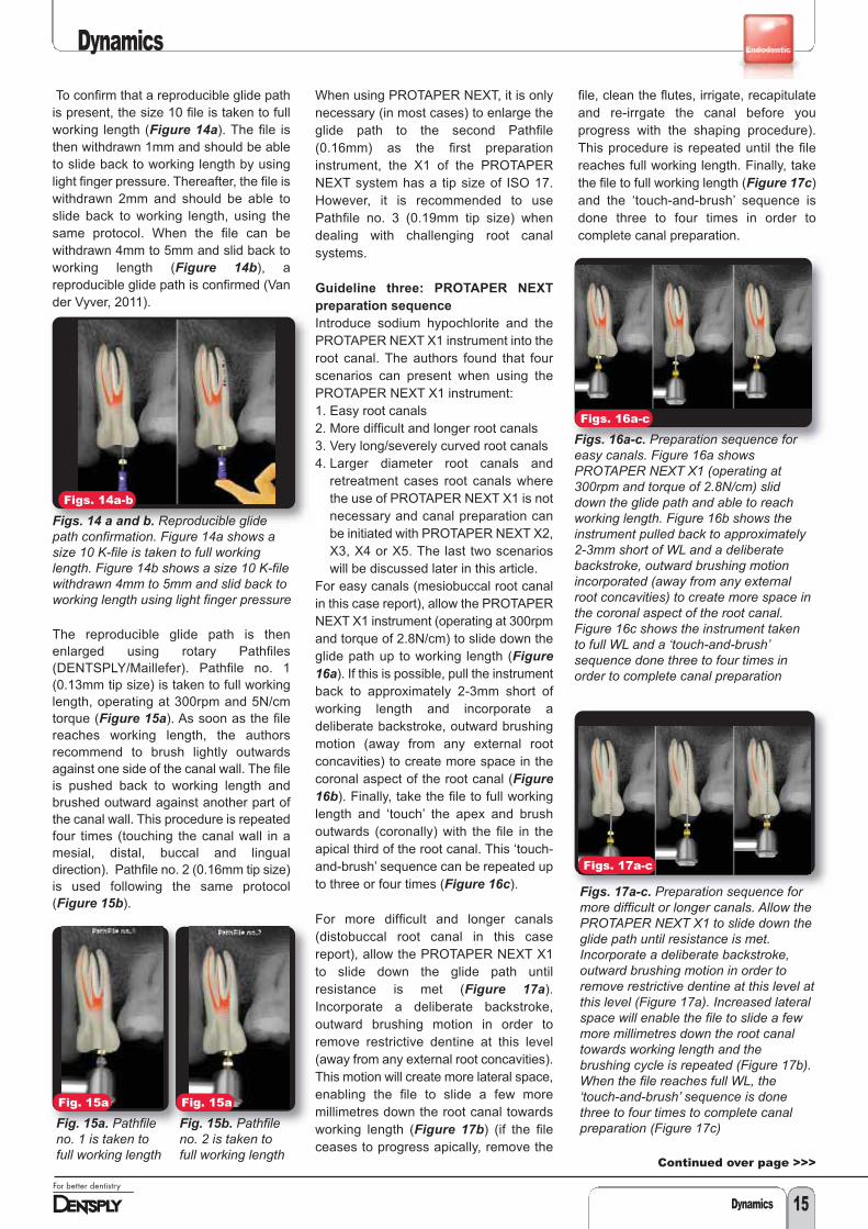
For easy canals (mesiobuccal root canalin this case report), allow the PROTAPERNEXT X1 instrument (operating at 300rpmand torque of 2.8N/cm) to slide down theglide path up to working length (Figure16a). If this is possible, pull the instrumentback to approximately 2-3mm short ofworking length and incorporate adeliberate backstroke, outward brushingmotion (away from any external rootconcavities) to create more space in thecoronal aspect of the root canal (Figure16b). Finally, take the file to full workinglength and ‘touch’ the apex and brushoutwards (coronally) with the file in theapical third of the root canal. This ‘touch-and-brush’ sequence can be repeated upto three or four times (Figure 16c).
For more difficult and longer canals(distobuccal root canal in this casereport), allow the PROTAPER NEXT X1to slide down the glide path untilresistance is met (Figure 17a).Incorporate a deliberate backstroke,outward brushing motion in order toremove restrictive dentine at this level(away from any external root concavities).This motion will create more lateral space,enabling the file to slide a few moremillimetres down the root canal towardsworking length (Figure 17b) (if the fileceases to progress apically, remove the
file, clean the flutes, irrigate, recapitulateand re-irrgate the canal before youprogress with the shaping procedure).This procedure is repeated until the filereaches full working length. Finally, takethe file to full working length (Figure 17c)and the ‘touch-and-brush’ sequence isdone three to four times in order tocomplete canal preparation.
Figs. 14a-b
Figs. 14 a and b. Reproducible glidepath confirmation. Figure 14a shows asize 10 K-file is taken to full workinglength. Figure 14b shows a size 10 K-filewithdrawn 4mm to 5mm and slid back toworking length using light finger pressure
Figs. 16a-c
Figs. 16a-c. Preparation sequence foreasy canals. Figure 16a showsPROTAPER NEXT X1 (operating at300rpm and torque of 2.8N/cm) sliddown the glide path and able to reachworking length. Figure 16b shows theinstrument pulled back to approximately2-3mm short of WL and a deliberatebackstroke, outward brushing motionincorporated (away from any externalroot concavities) to create more space inthe coronal aspect of the root canal.Figure 16c shows the instrument takento full WL and a ‘touch-and-brush’sequence done three to four times inorder to complete canal preparation
Figs. 17a-c
Figs. 17a-c. Preparation sequence formore difficult or longer canals. Allow thePROTAPER NEXT X1 to slide down theglide path until resistance is met.Incorporate a deliberate backstroke,outward brushing motion in order toremove restrictive dentine at this level atthis level (Figure 17a). Increased lateralspace will enable the file to slide a fewmore millimetres down the root canaltowards working length and thebrushing cycle is repeated (Figure 17b).When the file reaches full WL, the‘touch-and-brush’ sequence is donethree to four times to complete canalpreparation (Figure 17c)
Fig. 15a
Fig. 15a. Pathfileno. 1 is taken tofull working length
Fig. 15a
Fig. 15b. Pathfileno. 2 is taken tofull working length
Dynamics 15
Continued over page >>>

Dynamics
Dynamics16
After the use of PROTAPER NEXT X1, itis recommended to irrigate with sodiumhypochlorite, recapitulate with a smallpatency file to dislodge cutting debris andto re-irrigate to flush out all the dislodgeddebris from the root canal (Figures 18a-c).
PROTAPER NEXT X2 (first finishing
instrument)
Use PROTAPER NEXT X2 (25/06) to fullworking length, using the same protocolas described above. However, it isrecommended to use the ‘touch-and-brush’ sequence in the apical part of theroot canal only two to three times as afinal step (Figure 19). Excessive ‘touch-and-brush’ sequences in the apical part ofthe root canal can lead to transportationof the root canal. The root canal is againirrigated, recapitulated and re-irrigated.Gauging of apical foramen to determine ifthe preparation is complete.
Introduce a size 25/02 nickel titaniumhand file (DENTSPLY/Maillefer) to fullworking length (Figure 20). If the file issnug at working length it means that theapical foramen is prepared to a size ISO25 and the canal is adequately shaped. The palatal root canal in the present casereport was prepared with the PROTAPER
NEXT X1 and X2, according to theprotocol outlined above. In this case itwas found that the 25/02 nickel titaniumhand file was fitting loose at length and itcould be pushed past working length(Figure 21a) after canal preparation withthe X2 instrument. This indicated that theapical foramen was still larger than0.25mm. In these situations, it isrecommended to gauge the foramen witha size 30/02 nickel titanium hand file(Figure 21b). If the 30/02 file is snug atlength, the shape is complete.
If it is found that the 30/02 instrument fitstight, but short of the full working length(Figure 22a), it is recommended tocontinue canal preparation with thePROTAPER NEXT X3 (30/07) (Figure22b) and gauge again with the 30/02 nickeltitanium hand instrument (Figure 22c).
Guideline four: shaping
recommendations for PROTAPER
NEXT X3, X4 and X5
PROTAPER NEXT X3 (as well as X4 andX5 if necessary) is used in the samemanner as PROTAPER NEXT X1 or X2with the exception that the apicalpreparation is done by using the ‘touch-and-brush’ sequence only once or twicein the apical third of the root canal. Apicalgauging is done according to the abovementioned protocol using a size 30/02,40/02 or 50/02 nickel titaniuminstruments.
The 30/02 instrument was fitting snug atworking length in the palatal root canal inthe present case report. The canals wereobturated with PROTAPER NEXT X2gutta percha points in the mesiobuccaland distobuccal root canals and aPROTAPER NEXT X3 gutta percha pointin the palatal root canal as master conesusing the Calamus Dual Obturation Unit(DENTSPLY/Maillefer). Figure 23demonstrates the final result after canalobturation.
<<<<Continued from previous page
Figs. 18a-c
Figs. 18a-c. Irrigation solution isdeposited into the root canal before apatency file is used to dislodge anydebris inside the root canal. Finally, thedislodged debris is flushed out withfresh irrigation solution
Fig. 19
Fig. 19. PROTAPER NEXT X2 is takento full WL. The apical part of the rootcanal is prepared by using the ‘touch-and-brush’ sequence only two to threetimes with this instrument
Fig. 23
Fig. 23. Final result after obturationusing the Calamus Dual Obturation Unit(DENTSPLY/Maillefer)
Fig. 20
Fig. 20. Size 25/02nickel titanium handfile is used to gaugethe apical foramenof the prepareddistobuccal rootcanal. Note that thefile fits snug up tothe full WL
Fig. 22a
Fig. 22a. A 30/02NiTi handinstrument fitstight and short ofthe full workinglength (arrow)
Fig. 22b
Fig. 22b.Continue shapingwith aPROTAPERNEXT X3 (30/07)to full workinglength
Fig. 22c
Fig. 22c. Gaugeagain with a 30/02NiTi handinstrument. If theinstrument fits tightand at full workinglength the shape iscomplete
Fig. 21a
Fig. 21a. Size25/02 NiTi hand fileis used to gaugethe apical foramenof the preparedpalatal root canal.In this case it wasfound that the25/02 file was looseat length and itcould be pushedpast working length(arrow)
Fig. 21b
Fig. 21b. A size30/02 NiTi hand filethat fits snug atworking length,confirmed that theshape is complete
Dynamics 17
Dynamics
Preparation sequence for very long
and curved root canals
In selected clinical cases, the clinicianmight find that PROTAPER NEXT X1does not progress to full working lengtheven after a few coronal circumferentialbrushing motions. The authors thenrecommend to create more coronal shapeby using PROTAPER NEXT X1 followedby PROTAPER NEXT X2 up to two thirdsof the canal length. This preparationsequence will create enough lateral spacein the coronal two thirds of the root canalto ensure that PROTAPER NEXT X1 cannow be taken to full working lengthwithout any difficulty.
Case report
The patient, a 50-year-old female,presented with pain on her mandibularright first molar with a history of previousemergency root canal treatment. Clinicalexamination revealed a broken down andleaking temporary restoration, possiblyresulting in coronal leakage. A periapicalradiograph revealed very long and curvedmesial roots. Also visible on theradiograph was evidence of dentinetriangles, preventing straight-line accessinto the mesial root canals (Figure 24).
The defective temporary restoration andcaries were removed before the tooth wasrestored with composite and a newaccess cavity prepared. Note theevidence of dentine triangles on themesial aspect of the canal orifices (Figure25). The dentine triangles were removedwith a Protaper SX instrument, ensuringstraight-line access into all the rootcanals. Figure 26 shows the radiographicview of the length determinationconfirming straight-line access into theroot canals.
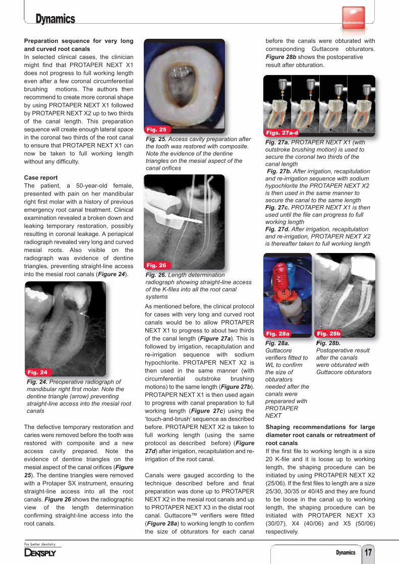
As mentioned before, the clinical protocolfor cases with very long and curved rootcanals would be to allow PROTAPERNEXT X1 to progress to about two thirdsof the canal length (Figure 27a). This isfollowed by irrigation, recapitulation andre-irrigation sequence with sodiumhypochlorite. PROTAPER NEXT X2 isthen used in the same manner (withcircumferential outstroke brushingmotions) to the same length (Figure 27b).PROTAPER NEXT X1 is then used againto progress with canal preparation to fullworking length (Figure 27c) using the‘touch-and-brush’ sequence as describedbefore. PROTAPER NEXT X2 is taken tofull working length (using the sameprotocol as described before) (Figure27d) after irrigation, recapitulation and re-irrigation of the root canal.
Canals were gauged according to thetechnique described before and finalpreparation was done up to PROTAPERNEXT X2 in the mesial root canals and upto PROTAPER NEXT X3 in the distal rootcanal. Guttacore™ verifiers were fitted(Figure 28a) to working length to confirmthe size of obturators for each canal
before the canals were obturated withcorresponding Guttacore obturators.Figure 28b shows the postoperative result after obturation.
Shaping recommendations for large
diameter root canals or retreatment of
root canals
If the first file to working length is a size20 K-file and it is loose up to workinglength, the shaping procedure can beinitiated by using PROTAPER NEXT X2(25/06). If the first files to length are a size25/30, 30/35 or 40/45 and they are foundto be loose in the canal up to workinglength, the shaping procedure can beinitiated with PROTAPER NEXT X3(30/07), X4 (40/06) and X5 (50/06)respectively.
Fig. 24
Fig. 24. Preoperative radiograph ofmandibular right first molar. Note thedentine triangle (arrow) preventingstraight-line access into the mesial rootcanals
Fig. 25
Fig. 25. Access cavity preparation afterthe tooth was restored with composite.Note the evidence of the dentinetriangles on the mesial aspect of thecanal orifices
Fig. 28b
Fig. 28b.Postoperative resultafter the canalswere obturated withGuttacore obturators
Figs. 27a-d
Fig. 27a. PROTAPER NEXT X1 (withoutstroke brushing motion) is used tosecure the coronal two thirds of thecanal lengthFig. 27b. After irrigation, recapitulationand re-irrigation sequence with sodiumhypochlorite the PROTAPER NEXT X2is then used in the same manner tosecure the canal to the same lengthFig. 27c. PROTAPER NEXT X1 is thenused until the file can progress to fullworking lengthFig. 27d. After irrigation, recapitulationand re-irrigation, PROTAPER NEXT X2is thereafter taken to full working length
Fig. 26
Fig. 26. Length determinationradiograph showing straight-line accessof the K-files into all the root canalsystems
Fig. 28a
Fig. 28a.Guttacoreverifiers fitted toWL to confirmthe size ofobturatorsneeded after thecanals werepreparared withPROTAPERNEXT

Achieving a balance between implant-supported restorationaesthetics and maintaining periodontal health is important in anoverall successful outcome of the prosthesis. The goal is to create anemergence profile design that allows for minimal tissue displacementwhile achieving optimal cervical contours for aesthetics. It isimportant in the design to allow access for proper cleaning by thepatient and clinician (Fig. 1).
There are two types of implant restoration designs commonly usedin single-tooth replacement prosthetics. They are a screw-retainedcrown or a two-piece abutment and cement-retained crown. Thescrew-retained crown design is the technique more commonly usedin Europe. Whereas, the cement retained crown prosthesis is morefrequently used in the United States.
The screw-retained restorations contain a small chimney access holewhere the screw retaining the restoration is inserted. The crown isscrewed directly into the implant and the access chimney is typicallyclosed with a tooth-coloured resin (Sarmont, 2009). There are twomain advantages of this restoration design. First, since cement is notused in this method, the opportunity for subgingival residual excesscement to remain on the prosthesis cannot occur. When excesscement is left, it can create the opportunity for inflammation and peri-implantitis to develop in the implant sulcus site. Second, the screwcan be easily removed from the restoration, allowing for crownremoval if necessary during any maintenance procedures.
The two-piece abutment and cement-retained crownrestoration has an abutment that is designed to provide thesubgingival emergence profile and allows the crown to becemented onto the abutment (Fig. 2). The emergence profilerefers to the subgingival contours that lie between theimplant platform and the emerging abutment and crown(Sarmont, 2009). Using a custom designed abutmentprovides greater flexibility in determining the proper shape ofthe emergence profile compared with pre-fabricatedstandard abutment design.
To obtain a pleasing restoration, the subgingival contoursmust start at the small circle of the implant head and emergefrom the tissue with an anatomical profile (Sarmont, 2009).The result should be an emergence profile that allows forminimal displacement of the surrounding tissue whilecreating an aesthetically pleasing appearance (Fig. 3). Thisdesign allows for easy access into the implant sulcus area socleaning and maintaining can be easily achieved by both thepatient and the clinician. Over or under contouring of theabutment and/or restoration can result in biofilm retentionand peri-implantitis. It is important for the emergence profileto resemble that of a natural tooth. Often the adjacent teethcan be used as a guide to determine the proper contours.
How implant prosthesisdesign influences implantmaintenance accessby Shirley Branam, RDH, MBA, and Gerhard Mora, CDT, BS
Dynamics
Fig. 1
Fig. 1. Emergence profile and crownshould resemble that of a natural toothso the patient and the clinician caneasily maintain the implant prosthesis.(Photos/Provided by G P Mora, CDT).
Fig. 2
Fig. 2. Custom abutment and crowndesign.
Fig. 3
Fig. 3. Ideal sulcus formation createdby proper emergence profile of theimplant abutment.
Dynamics18

The protocol for margin location of a standard implant restoration is still under debate. As the location of the crown abutment marginis placed deeper subgingival, the ability to access and maintain the site become more difficult (Linkevicius, 2012). What does this allmean for the clinician and patient in the maintenance of the implant prosthesis?
Access to the subginigivally area of the implant prosthesis for proper maintenance is vital to the health and success rate of theprosthesis. As margin location and emergence profiles extend farther subgingival, the ability to maintain these sites becomes morechallenging. Evidence has shown that power scalers with non-metallic tips can be beneficial in maintaining the implant prosthesis (Sato,2004). Several manufacturers offer tip designs that will accommodate the different types of power scalers. DENTSPLY Professionalhas an insert whose unique design allows a polymer sleeve to be assembled to the active tip area of this ultrasonic implant insert (Fig.4). When fully assembled, the Cavitron® SofTip™ Ultrasonic Implant Insert can easily be incorporated into a clinicians’ implantmaintenance procedure.
Incorporating ultrasonic scaling into the implant maintenance protocol may have several benefits. Combining mechanical movementand lavage can aid in the removal of biofilm and other debris in the implant prosthesis sulcus. Wilkins wrote in 2012: “Studies indicatecavitation is capable of destroying surface bacteria and can remove endotoxin from the root surface.” Additionally: “Oscillation of theultrasonic tip causes hydrodynamic waves to surround the tip. This acoustic turbulence is believed to have a disruptive effect onsurface bacteria” (Wilkins, 2012). Multiple in vitro studies have discussed that cavitation may have the potential to disrupt the cell wallof the bacteria, and acoustic turbulence is believed to have disruptive effect on the surface bacteria (Baehni, 1992; McInnes, 1993;Walmsley, 1990). However, further in vivo studies need to be conducted to determine if the same outcomes are achieved in the sulcus.
Another benefit to incorporating power scaling into the maintenance procedure is the ability to adapt the active tip area into the implantsulcus. Incorporating vertical adaptation of the active tip, at a 0 to 15-degree angle, to the implant restoration can allow for significantsubgingival surface contact for efficient deposit removal. When the emergence profile follows the anatomical shape of a natural tooth,this instrumentation technique can be an effective method of maintaining the site.
Finally, easy access for the patient is extremely important in the success of the implant prosthesis. There are a variety of interdentalbrushes, cleaners, and floss options available to the patient. It is important that the cleaners be easy to use, not cause tissue traumain the implant sulcus, or surface damage to the aesthetic materials in the restoration.
Dental implants are increasing in demand in part by their high success rates and the improved aesthetics they provide the patient. Akey to this success is having the proper design incorporated into the restoration. When designed properly, the implant restoration canbe easily maintained by both the patient and clinician.
Fig. 4
Fig. 4. Cavitron SofTip Ultrasonic Implant Insert(Photo/Provided by DENTSPLY Professional).
Gerhard (Gary) Mora, CDT, BS, is director of dentallaboratory support for the University of MichiganDental School. He earned an associate in appliedscience degree in dental technology and Bachelorof Science in business administration from FerrisState University, where he later was on the facultyin the dental technology program. He is a certified
Dental Technician and has more than 37 years of experience in dentistry.His expertise with dental materials research and digital dentistry hasresulted in original publications and presentations at meetings such asIADR/AADR and CEREC 25 & 27.5. He teaches in the advancededucation in general dentistry residency program and will be on staff forthe new computerised dentistry program starting in July. His expertiseincludes fixed prosthodontics, dental materials and digital dentistry.
Shirley Branam, RDH, MBA, is a clinicaleducator for DENTSPLY Professional, servingthe central region of the United States. Sheearned a Bachelor of Science in dentalhygiene from the University of Michigan andan MBA in health care management from theUniversity of Phoenix. She has more than 20
years of clinical and educational experience in the dental assistingand dental hygiene professions. While a member of the University ofMichigan School of Dentistry, she held various appointmentsincluding hygiene faculty member, staff hygienist in the graduateprosthodontic clinic and research coordinator assistant. Her areas ofexpertise include clinical dental hygiene, biomaterials, implants andlocal anesthesia.
About the authors
Dynamics
Dynamics 19