R1 SAFETY NOTICE PLEASE READ THIS ENTIRE MANUAL BEFORE YOU INSTALL AND USE YOUR NEW ROOM HEATER. FAILURE TO FOLLOW INSTRUCTIONS MAY RESULT IN PROPERTY DAMAGE, BODILY INJURY, OR EVEN DEATH. FOR USE IN THE U.S. AND CANADA. SUITABLE FOR INSTALLATION IN MOBILE HOMES IF THIS HARMAN STOVE IS NOT PROPERLY INSTALLED, A HOUSE FIRE MAY RESULT. FOR YOUR SAFETY, FOLLOW INSTALLATION DIRECTIONS. CONTACT LOCAL BUILDING OR FIRE OFFICIALS ABOUT RESTRICTIONS AND INSTALLATION INSPECTION REQUIREMENTS IN YOUR AREA. CONTACT YOUR LOCAL AUTHORITY (SUCH AS MUNICIPAL BUILDING DEPARTMENT, FIRE DEPARTMENT, FIRE PREVENTION BUREAU, ETC.) TO DETERMINE THE NEED FOR A PERMIT. CETTE GUIDE D'UTILISATION EST DISPONIBLE EN FRANCAIS. CHEZ VOTRE CONCESSIONNAIRE DE HARMAN STOVE COMPANY. SAVE THESE INSTRUCTIONS. The Harman PC 45 Corn/Pellet Stove Installation & Operating Manual R3 “Ce manuel est disponible en Français sur demande”
Transcript
R1
SAFETY NOTICE
PLEASE READ THIS ENTIRE MANUAL BEFORE YOU INSTALL AND USE YOUR NEW ROOM HEATER. FAILURE TOFOLLOW INSTRUCTIONS MAY RESULT IN PROPERTY DAMAGE, BODILY INJURY, OR EVEN DEATH.
FOR USE IN THE U.S. AND CANADA. SUITABLE FOR INSTALLATION IN MOBILE HOMES
IF THIS HARMAN STOVE IS NOT PROPERLY INSTALLED, A HOUSE FIRE MAY RESULT. FOR YOUR SAFETY, FOLLOWINSTALLATION DIRECTIONS.
CONTACT LOCAL BUILDING OR FIRE OFFICIALS ABOUT RESTRICTIONS AND INSTALLATION INSPECTIONREQUIREMENTS IN YOUR AREA.
CONTACT YOUR LOCAL AUTHORITY (SUCH AS MUNICIPAL BUILDING DEPARTMENT, FIRE DEPARTMENT, FIREPREVENTION BUREAU, ETC.) TO DETERMINE THE NEED FOR A PERMIT.
CETTE GUIDE D'UTILISATION EST DISPONIBLE EN FRANCAIS. CHEZ VOTRE CONCESSIONNAIRE DE HARMAN STOVECOMPANY.
SAVE THESE INSTRUCTIONS.
The Harman PC 45 Corn/Pellet Stove
Installation & Operating Manual
R3“Ce manuel est disponible en Français sur demande”
SAFETY NOTICE: IF THIS HARMAN STOVE IS NOT PROP-ERLY INSTALLED. A HOUSE FIRE MAY RESULT. FORYOUR SAFETY, FOLLOW THE INSTALLATION DIREC-TIONS CONTACT LOCAL BUILDING OR FIRE OFFICIALSABOUT RESTRICTIONS AND INSTALLATION INSPECTIONREQUIREMENTS IN YOUR AREA.
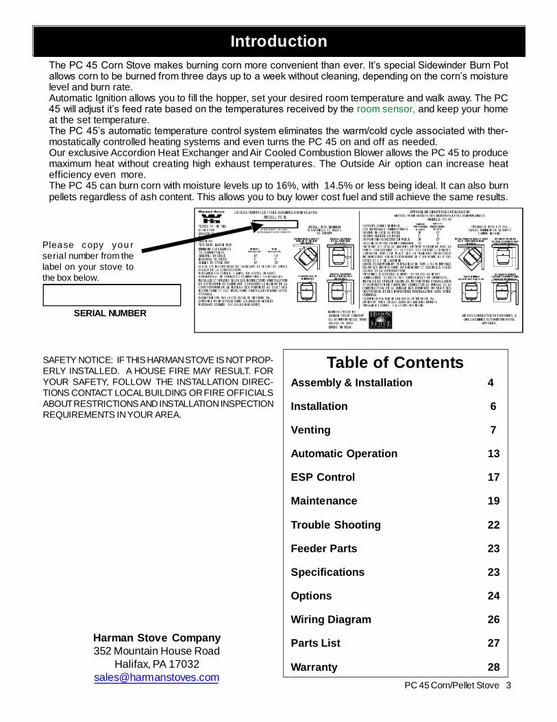
Please copy you rserial number from thelabel on your stove tothe box below.
SERIAL NUMBER
Assembly & Installation 4
Installation 6
Venting 7
Automatic Operation 13
ESP Control 17
Maintenance 19
Trouble Shooting 22
Feeder Parts 23
Specifications 23
Options 24
Wiring Diagram 26
Parts List 27
Warranty 28
Table of Contents
The PC 45 Corn Stove makes burning corn more convenient than ever. It’s special Sidewinder Burn Potallows corn to be burned from three days up to a week without cleaning, depending on the corn’s moisturelevel and burn rate.Automatic Ignition allows you to fill the hopper, set your desired room temperature and walk away. The PC45 will adjust it’s feed rate based on the temperatures received by the room sensor, and keep your homeat the set temperature.The PC 45’s automatic temperature control system eliminates the warm/cold cycle associated with ther-mostatically controlled heating systems and even turns the PC 45 on and off as needed.Our exclusive Accordion Heat Exchanger and Air Cooled Combustion Blower allows the PC 45 to producemaximum heat without creating high exhaust temperatures. The Outside Air option can increase heatefficiency even more.The PC 45 can burn corn with moisture levels up to 16%, with 14.5% or less being ideal. It can also burnpellets regardless of ash content. This allows you to buy lower cost fuel and still achieve the same results.
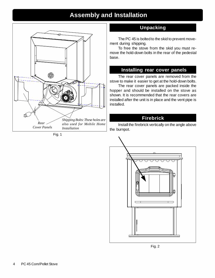
The PC 45 is bolted to the skid to prevent move-ment during shipping.
To free the stove from the skid you must re-move the hold-down bolts in the rear of the pedestalbase.
Installing rear cover panelsThe rear cover panels are removed from the
stove to make it easier to get at the hold-down bolts.The rear cover panels are packed inside the
hopper and should be installed on the stove asshown. It is recommended that the rear covers areinstalled after the unit is in place and the vent pipe isinstalled.
FirebrickInstall the firebrick vertically on the angle above
the burnpot.
RearCover Panels
Fig. 1
Fig. 2
Shipping Bolts: These holes arealso used for Mobile HomeInstallation
5PC 45 Corn/Pellet Stove
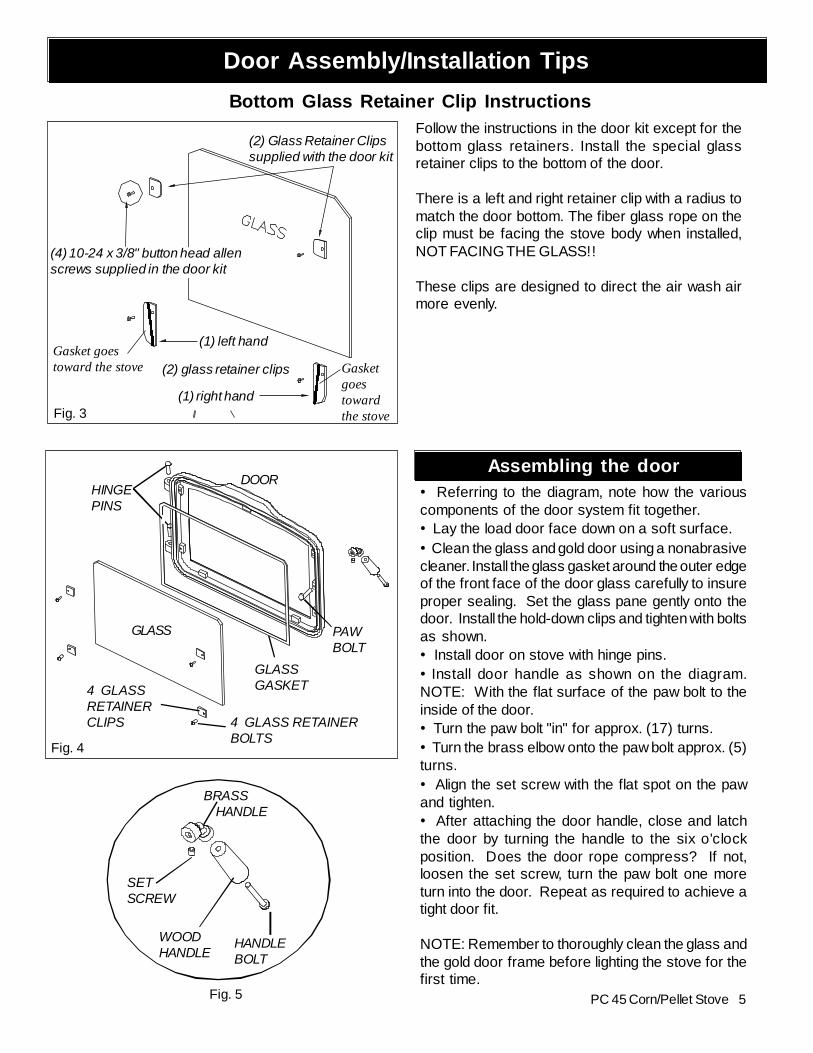
Door Assembly/Installation Tips
Assembling the door• Referring to the diagram, note how the variouscomponents of the door system fit together.• Lay the load door face down on a soft surface.• Clean the glass and gold door using a nonabrasivecleaner. Install the glass gasket around the outer edgeof the front face of the door glass carefully to insureproper sealing. Set the glass pane gently onto thedoor. Install the hold-down clips and tighten with boltsas shown.• Install door on stove with hinge pins.• Install door handle as shown on the diagram.NOTE: With the flat surface of the paw bolt to theinside of the door.• Turn the paw bolt "in" for approx. (17) turns.• Turn the brass elbow onto the paw bolt approx. (5)turns.• Align the set screw with the flat spot on the pawand tighten.• After attaching the door handle, close and latchthe door by turning the handle to the six o'clockposition. Does the door rope compress? If not,loosen the set screw, turn the paw bolt one moreturn into the door. Repeat as required to achieve atight door fit.
NOTE: Remember to thoroughly clean the glass andthe gold door frame before lighting the stove for thefirst time.
Bottom Glass Retainer Clip Instructions
(4) 10-24 x 3/8" button head allenscrews supplied in the door kit
(1) left hand
(2) glass retainer clips
(1) right hand
Follow the instructions in the door kit except for thebottom glass retainers. Install the special glassretainer clips to the bottom of the door.
There is a left and right retainer clip with a radius tomatch the door bottom. The fiber glass rope on theclip must be facing the stove body when installed,NOT FACING THE GLASS!!
These clips are designed to direct the air wash airmore evenly.
4 GLASSRETAINERCLIPS 4 GLASS RETAINER
BOLTS
GLASS
GLASSGASKET
DOORHINGEPINS
PAWBOLT
Fig. 3
(2) Glass Retainer Clipssupplied with the door kit
InstallingPlace the stove on a noncombustible floor protec-
tor that extends 6 inches to the front, 6 inches to thesides and 1 inch to the rear of the stove. The minimumfloor protector material is 24 gauge sheet metal.
Place the stove away from combustible walls at leastas far as shown in figures 6,7 & 8. Please note the differ-ence in side wall clearance with and without side shields.
Note that the clearances shown are minimum forsafety but do not leave much room for access when clean-ing or servicing. Please take this into account when plac-ing the stove.
Connect the power cord to a 120 V.A.C. 60Hzgrounded receptacle. (A surge protector is recommenedto protect the circuit board).
Prior to installing the flue pipe, connect a draft meterto the stove as shown in fig. 9. (The draft meter musthave a minimum range of 0"- 0.5"). Turn stove to "TEST"Mode and record the draft reading ______. After the fluepipe is connected, check the draft reading again makingsure all doors and windows in the home are closed. Ifthis reading is more than.05" higher than the unconnectedreading, check for possible restrictions or the need foroutside air. (See page 8).
Mobile Home InstallationWhen installing this unit in a mobile home several
requirements must be followed:1. The unit must be bolted to the floor. This can be done
with 1/4" lag screws through the 2 holes in the base plate.2. The unit must also be connected for the outside
air. See page 8.3. Floor protection and clearances must be followed
as shown.4. Unit must be grounded to the metal frame of the
mobile home.CAUTION: This appliance must be vented to the out-side.
Due to high temperatures, the stove should be placed out of trafficand away from furniture and draperies.
Children and adults should be alerted to the haz-ards of high surface temperatures and should stay awayto avoid burn to skin and/or clothing.
Young children should be carefully supervised whenthey are in the same room as the stove.
Clothing and other flammable materials should notbe placed on or near this unit.
Installation and repair of this Harman Stove shouldbe done by a qualified service person. The applianceshould be inspected before use and at least annually by aqualified service person. More frequent cleaning will berequired. It is imperative that control compartments, burn-ers, and circulating air passageways of the stove be keptclean.Mobile home installation should be done in accordancewith the Manufactured Home and Safety Standard (HUD),CFR 3280, Part 24.
7PC 45 Corn/Pellet Stove
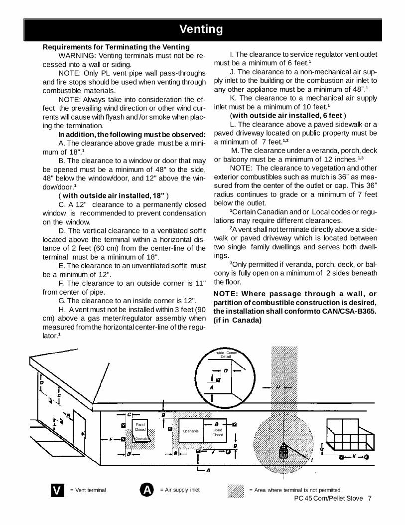
VentingRequirements for Terminating the Venting
WARNING: Venting terminals must not be re-cessed into a wall or siding.
NOTE: Only PL vent pipe wall pass-throughsand fire stops should be used when venting throughcombustible materials.
NOTE: Always take into consideration the ef-fect the prevailing wind direction or other wind cur-rents will cause with flyash and /or smoke when plac-ing the termination.
In addition, the following must be observed:A. The clearance above grade must be a mini-
mum of 18".1
B. The clearance to a window or door that maybe opened must be a minimum of 48" to the side,48" below the window/door, and 12" above the win-dow/door.1
( with outside air installed, 18” )C. A 12" clearance to a permanently closed
window is recommended to prevent condensationon the window.
D. The vertical clearance to a ventilated soffitlocated above the terminal within a horizontal dis-tance of 2 feet (60 cm) from the center-line of theterminal must be a minimum of 18".
E. The clearance to an unventilated soffit mustbe a minimum of 12".
F. The clearance to an outside corner is 11"from center of pipe.
G. The clearance to an inside corner is 12".H. A vent must not be installed within 3 feet (90
cm) above a gas meter/regulator assembly whenmeasured from the horizontal center-line of the regu-lator.1
I. The clearance to service regulator vent outletmust be a minimum of 6 feet.1
J. The clearance to a non-mechanical air sup-ply inlet to the building or the combustion air inlet toany other appliance must be a minimum of 48”.1
K. The clearance to a mechanical air supplyinlet must be a minimum of 10 feet.1
(with outside air installed, 6 feet )L. The clearance above a paved sidewalk or a
paved driveway located on public property must bea minimum of 7 feet.1,2
M. The clearance under a veranda, porch, deckor balcony must be a minimum of 12 inches.1,3
NOTE: The clearance to vegetation and otherexterior combustibles such as mulch is 36” as mea-sured from the center of the outlet or cap. This 36”radius continues to grade or a minimum of 7 feetbelow the outlet.
1Certain Canadian and or Local codes or regu-lations may require different clearances.
2A vent shall not terminate directly above a side-walk or paved driveway which is located betweentwo single family dwellings and serves both dwell-ings.
3Only permitted if veranda, porch, deck, or bal-cony is fully open on a minimum of 2 sides beneaththe floor.
NOTE: Where passage through a wall, orpartition of combustible construction is desired,the installation shall conform to CAN/CSA-B365.(if in Canada)
V A= Vent terminal = Air supply inlet
FixedClosed
Openable
Openable FixedClosed
Inside CornerDetail
= Area where terminal is not permitted
8 PC 45 Corn/Pellet Stove
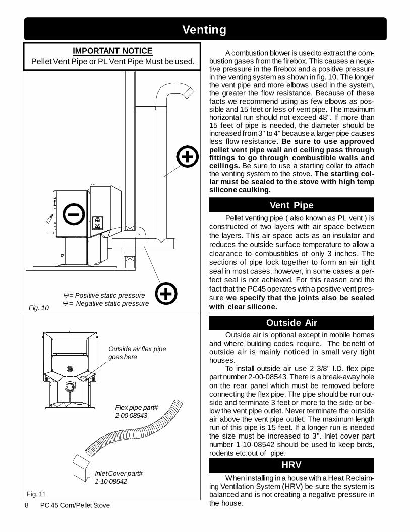
Outside air flex pipegoes here
Inlet Cover part#1-10-08542
Flex pipe part#2-00-08543
HRVWhen installing in a house with a Heat Reclaim-
ing Ventilation System (HRV) be sure the system isbalanced and is not creating a negative pressure inthe house.
Outside AirOutside air is optional except in mobile homes
and where building codes require. The benefit ofoutside air is mainly noticed in small very tighthouses.
To install outside air use 2 3/8" I.D. flex pipepart number 2-00-08543. There is a break-away holeon the rear panel which must be removed beforeconnecting the flex pipe. The pipe should be run out-side and terminate 3 feet or more to the side or be-low the vent pipe outlet. Never terminate the outsideair above the vent pipe outlet. The maximum lengthrun of this pipe is 15 feet. If a longer run is neededthe size must be increased to 3". Inlet cover partnumber 1-10-08542 should be used to keep birds,rodents etc.out of pipe.
Vent PipePellet venting pipe ( also known as PL vent ) is
constructed of two layers with air space betweenthe layers. This air space acts as an insulator andreduces the outside surface temperature to allow aclearance to combustibles of only 3 inches. Thesections of pipe lock together to form an air tightseal in most cases; however, in some cases a per-fect seal is not achieved. For this reason and thefact that the PC45 operates with a positive vent pres-sure we specify that the joints also be sealedwith clear silicone.
Venting
Fig. 11
A combustion blower is used to extract the com-bustion gases from the firebox. This causes a nega-tive pressure in the firebox and a positive pressurein the venting system as shown in fig. 10. The longerthe vent pipe and more elbows used in the system,the greater the flow resistance. Because of thesefacts we recommend using as few elbows as pos-sible and 15 feet or less of vent pipe. The maximumhorizontal run should not exceed 48". If more than15 feet of pipe is needed, the diameter should beincreased from 3" to 4" because a larger pipe causesless flow resistance. Be sure to use approvedpellet vent pipe wall and ceiling pass throughfittings to go through combustible walls andceilings. Be sure to use a starting collar to attachthe venting system to the stove. The starting col-lar must be sealed to the stove with high tempsilicone caulking.
IMPORTANT NOTICEPellet Vent Pipe or PL Vent Pipe Must be used.
9PC 45 Corn/Pellet Stove
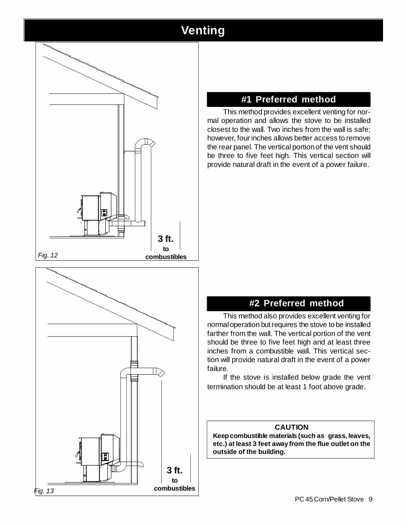
Fig. 12
3 ft.to
combustibles
3 ft.to
combustibles
Venting
#1 Preferred methodThis method provides excellent venting for nor-
mal operation and allows the stove to be installedclosest to the wall. Two inches from the wall is safe;however, four inches allows better access to removethe rear panel. The vertical portion of the vent shouldbe three to five feet high. This vertical section willprovide natural draft in the event of a power failure.
#2 Preferred methodThis method also provides excellent venting for
normal operation but requires the stove to be installedfarther from the wall. The vertical portion of the ventshould be three to five feet high and at least threeinches from a combustible wall. This vertical sec-tion will provide natural draft in the event of a powerfailure.
If the stove is installed below grade the venttermination should be at least 1 foot above grade.
CAUTIONKeep combustible materials (such as grass, leaves,etc.) at least 3 feet away from the flue outlet on theoutside of the building.
Fig. 13
10 PC 45 Corn/Pellet Stove
Fig. 14
Fig. 15
Venting
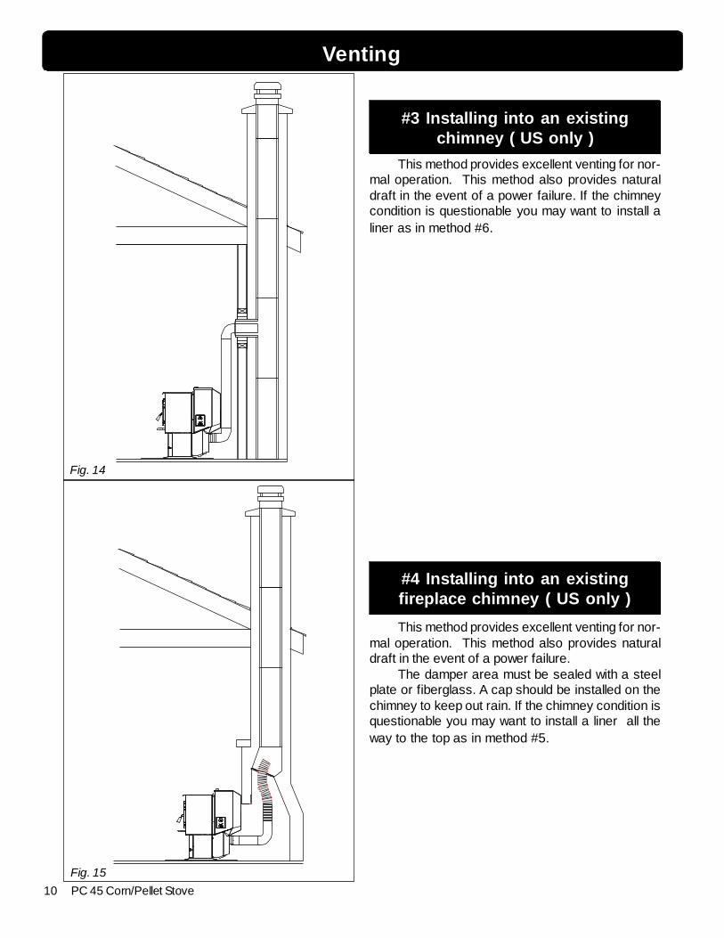
#3 Installing into an existingchimney ( US only )
This method provides excellent venting for nor-mal operation. This method also provides naturaldraft in the event of a power failure. If the chimneycondition is questionable you may want to install aliner as in method #6.
#4 Installing into an existingfireplace chimney ( US only )
This method provides excellent venting for nor-mal operation. This method also provides naturaldraft in the event of a power failure.
The damper area must be sealed with a steelplate or fiberglass. A cap should be installed on thechimney to keep out rain. If the chimney condition isquestionable you may want to install a liner all theway to the top as in method #5.
11PC 45 Corn/Pellet Stove
Fig. 16
Venting
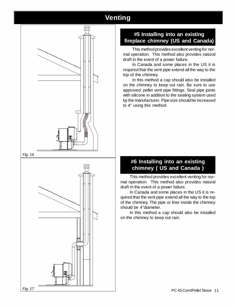
#5 Installing into an existingfireplace chimney (US and Canada)
This method provides excellent venting for nor-mal operation. This method also provides naturaldraft in the event of a power failure.
In Canada and some places in the US it isrequired that the vent pipe extend all the way to thetop of the chimney.
In this method a cap should also be installedon the chimney to keep out rain. Be sure to useapproved pellet vent pipe fittings. Seal pipe jointswith silicone in addition to the sealing system usedby the manufacturer. Pipe size should be increasedto 4" using this method.
#6 Installing into an existingchimney ( US and Canada )
This method provides excellent venting for nor-mal operation. This method also provides naturaldraft in the event of a power failure.
In Canada and some places in the US it is re-quired that the vent pipe extend all the way to the topof the chimney. The pipe or liner inside the chimneyshould be 4"diameter.
In this method a cap should also be installedon the chimney to keep out rain.
Fig. 17
12 PC 45 Corn/Pellet Stove
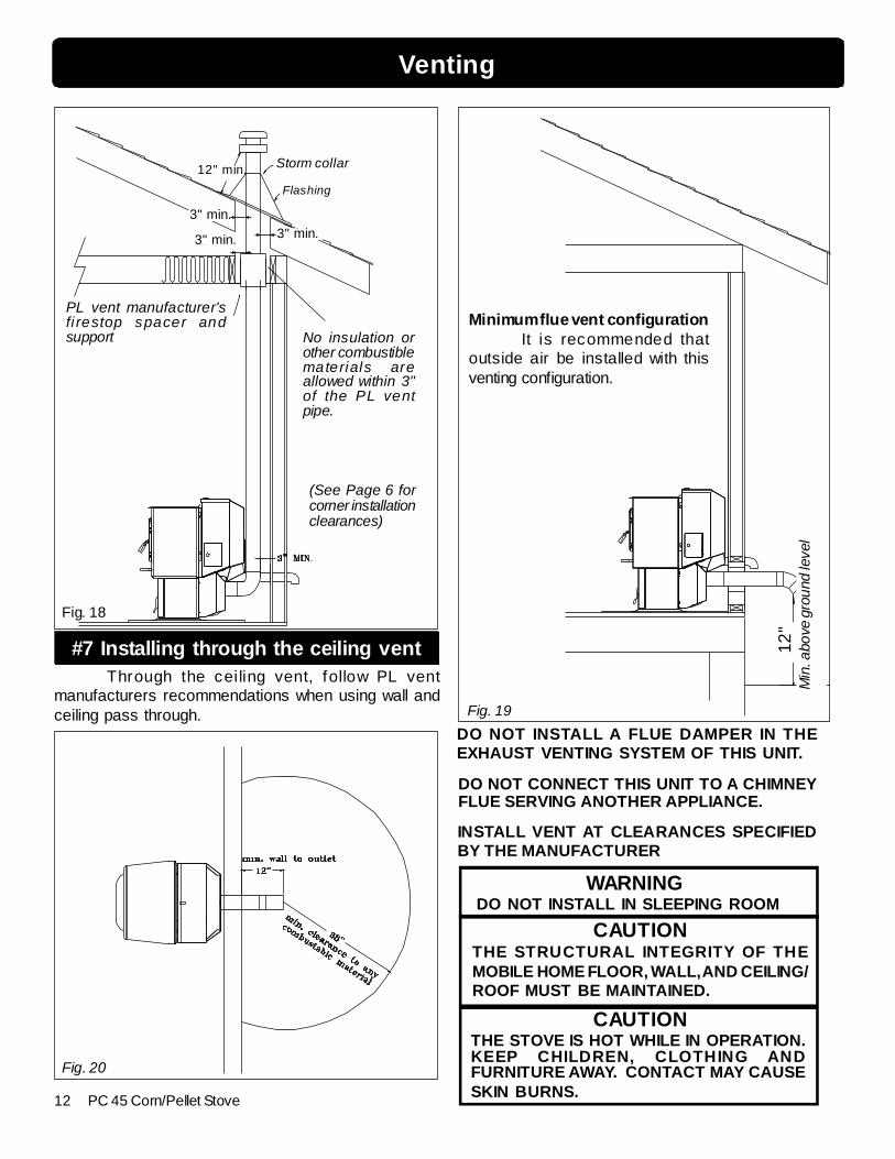
Fig. 18
No insulation orother combustiblematerials areallowed within 3"of the PL ventpipe.
PL vent manufacturer'sfi restop spacer andsupport
(See Page 6 forcorner installationclearances)
Minimum flue vent configurationIt is recommended that
outside air be installed with thisventing configuration.
Min
. abo
ve g
roun
d le
vel
12"
Storm collar
Flashing
3" min. 3" min.
12" min.
3" min.
Venting
Fig. 19
Fig. 20
#7 Installing through the ceiling ventThrough the ceiling vent, follow PL vent
manufacturers recommendations when using wall andceiling pass through.
DO NOT INSTALL A FLUE DAMPER IN THEEXHAUST VENTING SYSTEM OF THIS UNIT.
DO NOT CONNECT THIS UNIT TO A CHIMNEYFLUE SERVING ANOTHER APPLIANCE.
INSTALL VENT AT CLEARANCES SPECIFIEDBY THE MANUFACTURER
CAUTION
DO NOT INSTALL IN SLEEPING ROOMWARNING
CAUTIONTHE STRUCTURAL INTEGRITY OF THEMOBILE HOME FLOOR, WALL, AND CEILING/ROOF MUST BE MAINTAINED.
THE STOVE IS HOT WHILE IN OPERATION.KEEP CHILDREN, CLOTHING ANDFURNITURE AWAY. CONTACT MAY CAUSESKIN BURNS.
13PC 45 Corn/Pellet Stove
The PC45 corn/pellet stove is more than just automatic ignition, it is also automatic temperaturecontrol. The automatic system will allow the fire size to be adjusted to match the heating needsand even put the fire out if necessary. If heat is needed after the fire is out, the PC 45 willautomatically re-ignite and adjust the fire size to match the heating need. The totally automaticroom sensor mode is recommended because of its efficiency.The unit can be switched between "AUTO" and "MANUAL" at any time during operation.
AUTOMATIC IGNITION/OPERATION
Fig. 21:Room Temperature Mode: This setting will producea room temperature of 70 degrees with the distribution blowerat medium speed.
This setting will produce medium heat with thedistribution blower on "low".
This setting will produce continuous maximum heat outputwith the distribution blower at full speed.
Stove Temperature Mode
Igniter switch to "AUTO"
Room Temperature ModeIn "Room Temp Mode" heat output is controlled auto-
matically by the Room Sensing Probe. When the Room Sens-ing Probe calls for heat, the stove will increase output. Whenthe Room Sensing Probe is getting close to the set tempera-ture, the stove will begin to level off output and keep the fireburning at just the right temperature to maintain that setting.
High output is determined by the feed rate setting.This setting, generally on #2 (corn) or #4 (pellet), can beincreased if higher burn rates are necessary.
When burning corn the feed rate setting can be ad-justed anywhere within the yellow range with a #3 settingbeing the maximum setting, #1 the lowest setting. This set-ting will vary depending on the quality of corn used.
When burning pellets the feed rate setting can beadjusted within the full range between #1 on the low side to#6 on the high side.
Overfeeding is not a safety concern, but the fire maybe pushed off the burnpot and extinguish in the ash pan.
In "Room Temp Mode" a constant fuel consumption rateis sacrificed for exact room temperature. Therefore, as it getscolder more fuel will be burned automatically.
The distribution blower speed will vary according to theposition of the mode selector pointer, and fire size.
Igniter switch to "AUTO"
Stove Temperature ModeThis allows for automatic ignition upon start-up only.
The unit can then be set at any desired setting. The heatoutput and fuel consumption will remain constant regardlessof room temperature.
The unit's low burn or maintenance setting is as low as itwill go. It will not go out unless it runs out of fuel or is turned off.
Shut-Down ProcedureTo kill the fire or stop burning the stove, turn the Mode
Selector to "OFF". This will cause the fire to diminish andburn out. When the fire burns out and the stove cools downeverything will stop . NOTE: The combustion blowermotor will run for 5 hours after the stove is completelycool. This insures that all fuel in the burnpot and asheslocated in the ash pan are completely cold before shutdown of the combustion motor.
If you pull the plug to shut down the stove, all motors willstop. This may cause incomplete combustion and smoke inthe firebox. If the load door is opened the smoke may es-cape.
The best way to shut down the stove is simply let it runout of fuel, then the stove will shut down automatically.
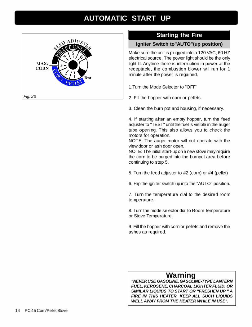
Fig. 22
14 PC 45 Corn/Pellet Stove
Starting the Fire
Igniter Switch to"AUTO"(up position)
Make sure the unit is plugged into a 120 VAC, 60 HZelectrical source. The power light should be the onlylight lit. Anytime there is interruption in power at thereceptacle, the combustion blower will run for 1minute after the power is regained.
1.Turn the Mode Selector to "OFF"
2. Fill the hopper with corn or pellets.
3. Clean the burn pot and housing, if necessary.
4. If starting after an empty hopper, turn the feedadjuster to "TEST" until the fuel is visible in the augertube opening. This also allows you to check themotors for operation.NOTE: The auger motor will not operate with theview door or ash door open.NOTE: The initial start-up on a new stove may requirethe corn to be purged into the burnpot area beforecontinuing to step 5.
5. Turn the feed adjuster to #2 (corn) or #4 (pellet)
6. Flip the igniter switch up into the "AUTO" position.
7. Turn the temperature dial to the desired roomtemperature.
8. Turn the mode selector dial to Room Temperatureor Stove Temperature.
9. Fill the hopper with corn or pellets and remove theashes as required.
AUTOMATIC START UP
"NEVER USE GASOLINE, GASOLINE-TYPE LANTERNFUEL, KEROSENE, CHARCOAL LIGHTER FLUID, ORSIMILAR LIQUIDS TO START OR "FRESHEN UP " AFIRE IN THIS HEATER. KEEP ALL SUCH LIQUIDSWELL AWAY FROM THE HEATER WHILE IN USE".
Warning
Fig. 23
15PC 45 Corn/Pellet Stove
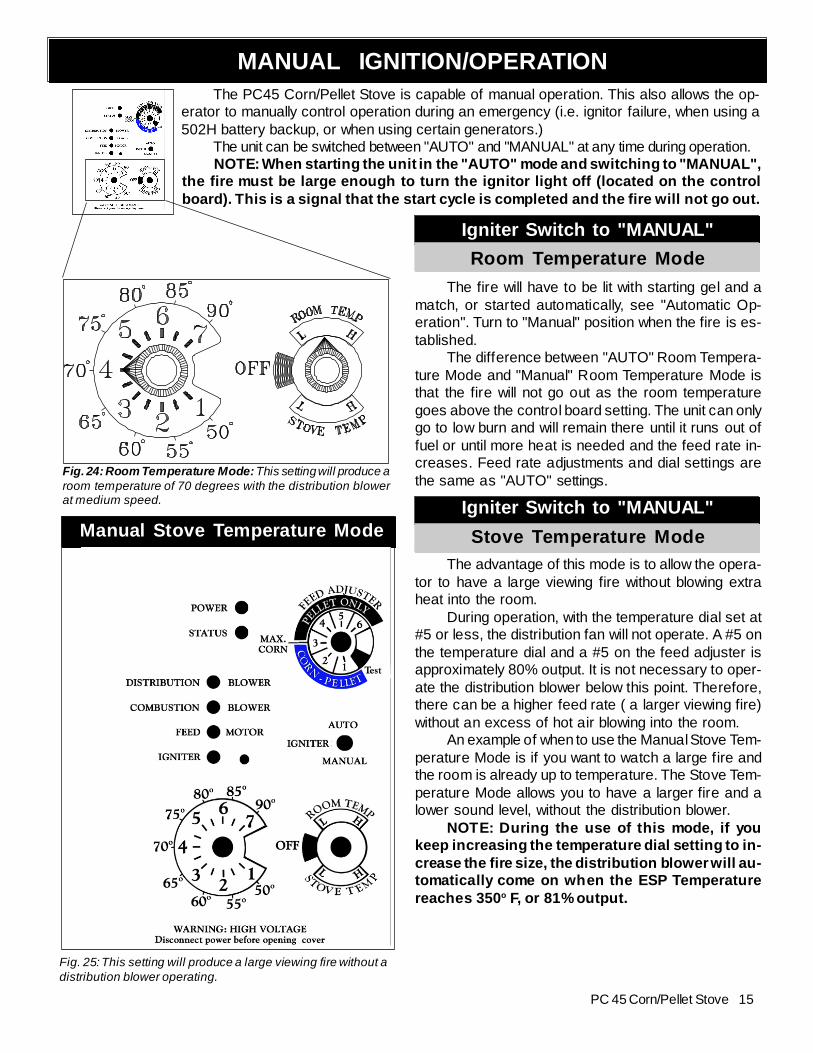
The PC45 Corn/Pellet Stove is capable of manual operation. This also allows the op-erator to manually control operation during an emergency (i.e. ignitor failure, when using a502H battery backup, or when using certain generators.)
The unit can be switched between "AUTO" and "MANUAL" at any time during operation.NOTE: When starting the unit in the "AUTO" mode and switching to "MANUAL",
the fire must be large enough to turn the ignitor light off (located on the controlboard). This is a signal that the start cycle is completed and the fire will not go out.
MANUAL IGNITION/OPERATION
Manual Stove Temperature Mode
Fig. 24: Room Temperature Mode: This setting will produce aroom temperature of 70 degrees with the distribution blowerat medium speed.
OO
Igniter Switch to "MANUAL"
Room Temperature Mode
The fire will have to be lit with starting gel and amatch, or started automatically, see "Automatic Op-eration". Turn to "Manual" position when the fire is es-tablished.
The difference between "AUTO" Room Tempera-ture Mode and "Manual" Room Temperature Mode isthat the fire will not go out as the room temperaturegoes above the control board setting. The unit can onlygo to low burn and will remain there until it runs out offuel or until more heat is needed and the feed rate in-creases. Feed rate adjustments and dial settings arethe same as "AUTO" settings.
Igniter Switch to "MANUAL"
Stove Temperature ModeThe advantage of this mode is to allow the opera-
tor to have a large viewing fire without blowing extraheat into the room.
During operation, with the temperature dial set at#5 or less, the distribution fan will not operate. A #5 onthe temperature dial and a #5 on the feed adjuster isapproximately 80% output. It is not necessary to oper-ate the distribution blower below this point. Therefore,there can be a higher feed rate ( a larger viewing fire)without an excess of hot air blowing into the room.
An example of when to use the Manual Stove Tem-perature Mode is if you want to watch a large fire andthe room is already up to temperature. The Stove Tem-perature Mode allows you to have a larger fire and alower sound level, without the distribution blower.
NOTE: During the use of this mode, if youkeep increasing the temperature dial setting to in-crease the fire size, the distribution blower will au-tomatically come on when the ESP Temperaturereaches 350o F, or 81% output.
Fig. 25: This setting will produce a large viewing fire without adistribution blower operating.
16 PC 45 Corn/Pellet Stove
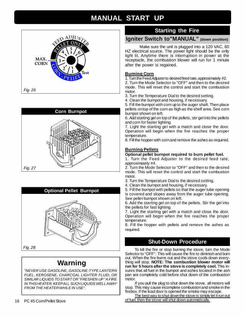
MANUAL START UP
Starting the Fire
Igniter Switch to"MANUAL" (down position)
Make sure the unit is plugged into a 120 VAC, 60HZ electrical source. The power light should be the onlylight lit. Anytime there is interruption in power at thereceptacle, the combustion blower will run for 1 minuteafter the power is regained.
Burning Corn1. Turn the Feed Adjuster to desired feed rate, approximately #2.2. Turn the Mode Selector to "OFF" and then to the desiredmode. This will reset the control and start the combustionmotor.3. Turn the Temperature Dial to the desired setting.4. Clean the burnpot and housing, if necessary.5. Fill the burnpot with corn up to the auger shaft. Then placepellets on top of the corn as high as the shelf area. See cornburnpot shown on left.6. Add starting gel on top of the pellets, stir gel into the pelletsand corn for faster lighting.7. Light the starting gel with a match and close the door.Operation will begin when the fire reaches the propertemperature.8. Fill the hopper with corn and remove the ashes as required.
Burning PelletsOptional pellet burnpot required to burn pellet fuel.1. Turn the Feed Adjuster to the desired feed rate,approximately #4.2. Turn the Mode Selector to "OFF" and then to the desiredmode. This will reset the control and start the combustionmotor.3. Turn the Temperature Dial to the desired setting.4. Clean the burnpot and housing, if necessary.5. Fill the burnpot with pellets so that the auger tube openingis covered and slopes away from the auger tube opening.See pellet burnpot shown on left.6. Add the starting gel on top of the pellets. Stir the gel intothe pellets for fast lighting.7. Light the starting gel with a match and close the door.Operation will begin when the fire reaches the propertemperature.8. Fill the hopper with pellets and remove the ashes asrequired.
Fig. 26
Corn Burnpot
Optional Pellet Burnpot
"NEVER USE GASOLINE, GASOLINE-TYPE LANTERNFUEL, KEROSENE, CHARCOAL LIGHTER FLUID, ORSIMILAR LIQUIDS TO START OR "FRESHEN UP " A FIREIN THIS HEATER. KEEP ALL SUCH LIQUIDS WELL AWAYFROM THE HEATER WHILE IN USE".
Warning
Fig. 27
Fig. 28Shut-Down Procedure
To kill the fire or stop burning the stove, turn the ModeSelector to "OFF". This will cause the fire to diminish and burnout. When the fire burns out and the stove cools down every-thing will stop. NOTE: The combustion blower motor willrun for 5 hours after the stove is completely cool. This in-sures that all fuel in the burnpot and ashes located in the ashpan are completely cold before shut down of the combustionmotor.
If you pull the plug to shut down the stove, all motors willstop. This may cause incomplete combustion and smoke in thefirebox. If the load door is opened the smoke may escape.
The best way to shut down the stove is simply let it run outof fuel, then the stove will shut down automatically.
17PC 45 Corn/Pellet Stove
AUTOMATIC IGNITION ESP CONTROLFeed adjusterSets the maximumfeed rate
TestRuns all motors at fullspeed for one minuteto check operation.After two minutes thes tove wil l go tominimum burn andthe b lowers wil lalternate from high tolow every minute toremind you that youare s ti ll in "Tes tMode".
Igniter switchSet to appropriateStart-Up mode.
Distribution Blowerspeed adjustment range.L = lowH = highVariable speed anywherebetween L and H;although as the stovetemp. goes up , so doesthe L and H scale.
Temp dialAllows you to adjust the room temperature in RoomTemp Mode using the outer scale marked in degreesFahrenheit. It also allows you to adjust the stovetemperature while in Stove Temp Mode using the innerscale marked from 1 to 7.
Mode SelectorAllows you to choosebetween Room Temp Mode,Stove Temp Mode, or OFF.Also allows you to vary thedistribution blower speed byturning the knob to the highor low side of each mode.
Power LightIndicates power to thecontrol.
Indicates power to thefeed motor.
Indicates igniter is on.
Indicates power tocombustion blower
Status LightWill be lit in either stoveor room temp mode whenpointer is not within offposition band exceptafter normal shut down.Blinks to indicate errorslisted below.
Indicates power todistribution blower.
6 Blinks : Indicates that the control has calculatedpoor or incomplete combustion occurring for morethan 50 minutes. See Troubleshooting section formore details.A six blink status may be set if the stove is allowedto run out of pellets. To reset, turn mode selector to"OFF" then back on to the desired mode. If the unitwas not out of pellets, see Troubleshooting section,Page 24, for more details.* Manual reset- Disconnect power cord for a fewseconds and reconnect. If error still occurs call yourHarman Dealer.
Status light error messages:
1 Blink: Indicates control board self diagnostic fail-ure. This requires a manual reset*.3 Blinks: Indicates ESP (Exhaust Sensing Probe)failure. This requires a manual reset*.4 Blinks: Can occur only in Room Temp Mode andindicates Room Sensing Probe failed or not installed.If a Room Sensing Probe is then installed, the sta-tus light will automatically reset.NOTE: Unit will not start in "AUTO" with this statuserror.5 Blinks (In Igniter Auto. Mode Only): Indicatesthat the unit has failed to light within the 45 minutestart cycle. To reset - Turn Mode Selector to "OFF",then turn to either mode again.
Dealer Diagnostic PortFor dealer maintenance useonly. Requires special DDMmonitor supplied to HarmanDealers exclusively.
18 PC 45 Corn/Pellet Stove
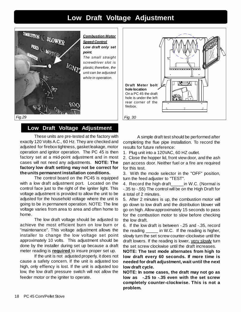
These units are pre-tested at the factory withexactly 120 Volts A.C., 60 Hz. They are checked andadjusted for firebox tightness, gasket leakage, motoroperation and ignitor operation. The PC 45 is thenfactory set at a mid-point adjustment and in mostcases will not need any adjustments. NOTE: Thefactory low draft setting may not be correct forthe units permanent installation conditions.
The control board on the PC45 is equippedwith a low draft adjustment port. Located on thecontrol face just to the right of the igniter light. Thisvoltage adjustment is provided to allow the unit to beadjusted for the household voltage where the unit isgoing to be in permanent operation. NOTE: The linevoltage varies from area to area and often home tohome.
The low draft voltage should be adjusted toachieve the most efficient burn on low burn or"maintenance". This voltage adjustment allows theinstaller to change the low voltage set pointapproximately 10 volts. This adjustment should bedone by the installer during set up because a draftmeter reading is required to insure proper set up.
If the unit is not adjusted properly, it does notcause a safety concern. If the unit is adjusted toohigh, only effiency is lost. If the unit is adjusted toolow, the low draft pressure switch will not allow thefeeder motor or the igniter to operate.
Combustion Motor
Speed Control
Low draft only setpoint.The small straightscrewdriver slot isplastic; therefore, theunit can be adjustedwhile in operation.
Fig.29 Fig. 30
A simple draft test should be performed aftercompleting the flue pipe installation. To record theresults for future reference:1. Plug unit into a 120VAC, 60 HZ outlet.2. Close the hopper lid, front view door, and the ashpan access door. Neither fuel or a fire are requiredfor this test.3. With the mode selector in the "OFF" position,turn the feed adjuster to "TEST".4. Record the high draft_____in W.C. (Normal is-.35 to -.55) The control will be on the High Draft fora total of 2 minutes.5. After 2 minutes is up, the combustion motor willgo down to low draft and the distribution blower willgo on high. Allow approximately 15 seconds to passfor the combustion motor to slow before checkingthe low draft.6. If the low draft is between -.25 and -.35, recordthe reading _____ in W.C. If the reading is higher,slowly turn the set screw counter-clockwise until thedraft lowers. If the reading is lower, very slowly turnthe set screw clockwise until the draft increases.NOTE: The test mode alternates from high tolow draft every 60 seconds. If more time isneeded for draft adjustment, wait until the nextlow draft cycle.NOTE: In some cases, the draft may not go aslow as -.25 to -.35 even with the set screwcompletely counter-clockwise. This is not aproblem.
Low Draft Voltage Adjustment
Draft Meter bo lthole locationOn a PC 45 the drafthole is under the leftrear corner of thefirebox.
Low Draft Voltage Adjustment
19PC 45 Corn/Pellet Stove
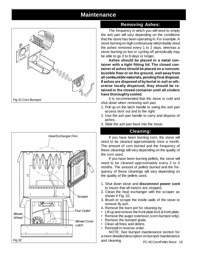
Removing Ashes:The frequency in which you will need to empty
the ash pan will vary depending on the conditionsthat the stove has been operating in. For example: Astove burning on high continuously will probably needthe ashes removed every 1 to 2 days, whereas astove burning on low or cycling off periodically maybe able to go 3 to 8 days or longer.
Ashes should be placed in a metal con-tainer with a tight fitting lid. The closed con-tainer of ashes should be placed on a noncom-bustible floor or on the ground, well away fromall combustible materials, pending final disposal.If ashes are disposed of by burial in soil or oth-erwise locally dispersed, they should be re-tained in the closed container until all cindershave thoroughly cooled.
It is recommended that the stove is cold andshut down when removing ash pan.1. Pull up on the latch handle to swing the ash pan
access door out and to the right.2. Use the ash pan handle to carry and dispose of
ashes.3. Slide the ash pan back into the stove.
Cleaning:If you have been burning corn, the stove will
need to be cleaned approximately once a month.The amount of corn burned and the frequency ofthese cleanings will vary depending on the quality ofthe corn used.
If you have been burning pellets, the stove willneed to be cleaned approximately every 2 to 3months. The amount of pellets burned and the fre-quency of these cleanings will vary depending onthe quality of the pellets used.
1. Shut down stove and disconnect power cordto insure that all motors are stopped.
2. Clean the heat exchanger with the scraper asshown if Fig. 32.
3. Brush or scrape the inside walls of the stove toremove fly ash.
4. Remove the burn pot for cleaning by:• Lift up and remove the front plate lock & front plate.• Remove the auger extension (corn burnpot only).• Remove the burnpot grate.• Clean all fines and debris.• Reinstall in reverse order.
NOTE: See burnpot maintenance section fora more detailed description on burnpot maintenanceand cleaning.
Maintenance
Scraper
Blower CoverLatch
BlowerWheel
Flue Outlet
Heat Exchanger Fins
Fig 32
Fig 31 Corn Burnpot
20 PC 45 Corn/Pellet Stove
ESP Probe
Fig. 39
Be careful not todamage ESP probewhen cleaning withbrush.
Maintenance(Cleaning continued)5. Remove the ash pan.6. Remove the combustion blower cover by turningthe blower cover latch vertical as shown in fig. 32.Slide the cover out of the slot on the left. This willexpose the combustion blower wheel and flue outlet,fig. 35.7. Clean the blower wheel with a brush and a vacuumcleaner.8. Use a brush to clean the flue, being careful not todamage the ESP probe. The flue goes straightthrough into the vent pipe therefore, the vent pipecan also be cleaned to some extent through the flueoutlet.9. Reinstall the blower cover and relatch.10. Slide ash pan into the stove and latch into place.
Cleaning of Feeder Fines Area1. Remove the rear shields to access the feedercover.2. Remove the wing nut on the feeder cover andslide the cover off the threaded rod.3. Remove all fines with a vacuum.
Fig. 37
Brush notsupplied. Can befound inhardware stores.
Fig. 33: Latch "closed "withblower cover in place. Burnpot clean-out is closed.
Fig. 34
ESP probe
Fig. 35: Exposed blowerwheel and flue opening,NOTE: ESP probe is visible.
Fig. 36: Blower coverremoved.
Soot and Fly AshThe products of combustion will contain small
particles of fly ash. The fly ash will collect in theexhaust venting system and restrict the flow of theflue gases. Incomplete combustion, such as oc-curs during startup, shutdown, or incorrect opera-tion of the room heater, will lead to some soot for-mation which will collect in the exhaust venting sys-tem. The exhaust venting system should be in-spected after the first month of burning to determinethe frequency of cleaning that will be required. NOTE:The frequency could vary from once a month to oncea season depending on the quality of the fuel beingused.
Fig. 38: For further details see exploded view on page 23.
21PC 45 Corn/Pellet Stove
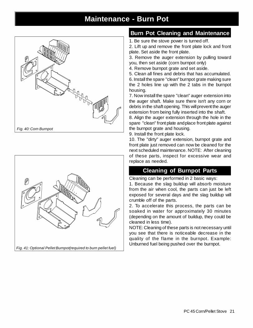
Burn Pot Cleaning and Maintenance1. Be sure the stove power is turned off.2. Lift up and remove the front plate lock and frontplate. Set aside the front plate.3. Remove the auger extension by pulling towardyou, then set aside (corn burnpot only)4. Remove burnpot grate and set aside.5. Clean all fines and debris that has accumulated.6. Install the spare "clean" burnpot grate making surethe 2 holes line up with the 2 tabs in the burnpothousing.7. Now install the spare "clean" auger extension intothe auger shaft. Make sure there isn't any corn ordebris in the shaft opening. This will prevent the augerextension from being fully inserted into the shaft.8. Align the auger extension through the hole in thespare "clean" front plate and place front plate againstthe burnpot grate and housing.9. Install the front plate lock.10. The "dirty" auger extension, burnpot grate andfront plate just removed can now be cleaned for thenext scheduled maintenance. NOTE: After cleaningof these parts, inspect for excessive wear andreplace as needed.
Cleaning of Burnpot PartsCleaning can be performed in 2 basic ways:1. Because the slag buildup will absorb moisturefrom the air when cool, the parts can just be leftexposed for several days and the slag buildup willcrumble off of the parts.2. To accelerate this process, the parts can besoaked in water for approximately 30 minutes(depending on the amount of buildup, they could becleaned in less time).NOTE: Cleaning of these parts is not necessary untilyou see that there is noticeable decrease in thequality of the f lame in the burnpot. Example:Unburned fuel being pushed over the burnpot.
Maintenance - Burn Pot
Fig. 40: Corn Burnpot
Fig. 41: Optional Pellet Burnpot(required to burn pellet fuel)
22 PC 45 Corn/Pellet Stove
FEEDER DOES NOT FEED1. No fuel in hopper.2. Firebox draft may be too low for low draft pres-sure switch in feeder circuit to operate. Check forclosed doors, loose or missing gasket on doorsor hopper lid, faulty pressure switch.3. Feed motor will not run until ESP senses 200o F.Maybe you did not put enough pellets in the burnpot before lighting the fire.4. Something is restricting flow in the hopper orcausing the slide plate to stick.5. Feed motor has failed.
PARTIALLY BURNED FUEL1. Feed rate too high.2. Draft too low.3. Burn pot may need to be cleaned.4. Combination of all the above.5. #6 status blink: A 6 blink control board statusindication is caused by poor or incomplete com-bustion. The circuit board has the ability to trackthe combustion through feed settings and ESP tem-peratures. When the control board has calculatedpoor or incomplete combustion it will shut downthe unit as a safety feature. (Poor or incompletecombustion is a contributer of creasote which maycause a chimney fire)A 6 blink status may be caused by several things:1. Blocked or partially blocked flue.2. Blocked or partially blocked inlet air.
a. backdraft damper on the inlet pipe may bestuck closed.
b. if outside air is installed the inlet cover may beblocked.3. The air chamber under the burnpot may be filledwith fines and small bits of ash.4. The holes in the burnpot may be getting filledwith ash or carbon buildup.5. Combustion blower fan blades may needcleaned.6. There is no fuel in the hopper.
COMBUSTION BLOWER RUNS AFTER SHUT DOWNThis is a normal function. The combustion blowerwill run for 5 hours after the stove is completelycool.
SMOKE SMELLSeal the vent pipe joints and connection to stovewith silicone.
FIRE HAS GONE OUT1. No fuel in hopper.2. Draft setting is too low.3. Something is restricting fuel flow.4. Feed motor or draft motor has failed.5. Power failure or blown fuse.
SMOKE IS VISIBLE COMING OUT OF VENT1. Air-fuel ratio is too rich.
A. Feed rate too high.B. Draft too low caused by a gasket leak.
2. Unit is in an ignition cycle.
LOW HEAT OUTPUT1. Feed rate too low2. Temperature setting too low (Stove Temp Mode)3. Draft too low because of gasket leak.4. Poor quality or high moisture fuel.
PC 45 Trouble-Shooting
Cleaning Burn PotWhenever your stove is not burning, take the
opportunity to scrape the burn pot to remove car-bon buildup. A vacuum cleaner is handy to removethe residue. Be sure the stove is cold if you use avacuum.
Carbon buildup can be scraped loose with thefire burning using the special tool provided with yourstove. Scrape the sides of the burnpot (corn grate),and the floor and sides (pellet grate). The carbonwill be pushed out by the incoming fuel. Always weargloves to do this.
Removing AshesTurn the Temp Dial to number 1 approximately
30 minutes before removing ashes. This will resultin a cooler stove and ash pan.
Maximum Feed Adjuster settings are notneeded in most cases. Operating in the normalrange (#2 corn) (#4 pellet) is recommended whenmaximum heat output is not required. The ESPprobe prevents the stove from being over-fired.
Keep the stove free of dust and dirt.
Fuel
The PC 45 can burn corn with moisture levelsup to 16%, with 14.5% or less ideal.
Pellet fuels are put into 3 categories in terms ofash content. Premium at 1% or less, Standard at3% or less and all others at 3% or more.
The PC 45 is capable of burning all 3 catego-ries of pellets due to a patented feeder and burn potsystem.
It should be noted, however, that higher ash con-tent will require more frequent ash removal and mayprovide less BTU's per pound. Normally, standardand high ash pellets cost less than premium pelletsand can be cost effective when burned in the PC 45.
The moisture content of pellets must not exceed8%. Higher moisture will rob BTU's and may not burnproperly.
Helpful Hints
23PC 45 Corn/Pellet Stove
Weight 249 lbs.Blower 135 cfmFeed Rate 0 to 5.0 lbs. per hr.Hopper Capacity 80 lbs.Fuel Corn & Wood PelletsFlue Size 3 inchOutside Air Size 2 3/8" I.D.Fuse Rating 6 amp
32.3
75"
9"
23.5"
34.5
"
5.250"
12.3
75"
29.5
"
P61A Feeder
Specifications
Feeder and Specifications
Feeder Body Weldment1-10-02681
Igniter Element: 3-20-02677
Igniter Mounting Bracket: 2-00-724121
Auger : 3-50-00465
Bearing Retainer: 2-00-04035
Auger Mounting Bolts: 3-30-1311812513
Air Pump: 3-20-02679Air Pump Mounting Hardware :
BHSCS 8'32 x 1/4: 3-30-3108320252
3/8 MPT x 1/4" Barb Brass Inlet Fitting: 3-10-724203
Pusher Arm Mtng.Bolts(4)3-30-2252005013
Pusher Arm Weldment1-10-08535
Cast Cover Gasket3-44-00659
Cast Cover Assembly1-10-00894
5/16" Wingnut3-30-8131181
Pusher Arm MTNG. Nuts(2)3-30-80252013
Pillow Block Bearing3-31-3614087
Slide Plate1-10-08037
Differential Switch: 3-20-9301
Slab Base T-nut:: 3-31-23756186
Gearmotor Assembly: 1-10-00697Includes: Motor Mount
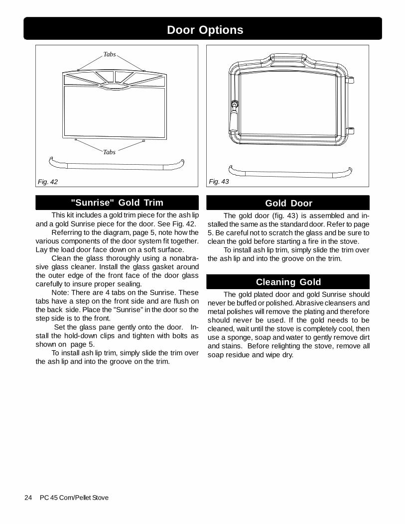
"Sunrise" Gold TrimThis kit includes a gold trim piece for the ash lip
and a gold Sunrise piece for the door. See Fig. 42.Referring to the diagram, page 5, note how the
various components of the door system fit together.Lay the load door face down on a soft surface.
Clean the glass thoroughly using a nonabra-sive glass cleaner. Install the glass gasket aroundthe outer edge of the front face of the door glasscarefully to insure proper sealing.
Note: There are 4 tabs on the Sunrise. Thesetabs have a step on the front side and are flush onthe back side. Place the "Sunrise" in the door so thestep side is to the front.
Set the glass pane gently onto the door. In-stall the hold-down clips and tighten with bolts asshown on page 5.
To install ash lip trim, simply slide the trim overthe ash lip and into the groove on the trim.
Gold DoorThe gold door (fig. 43) is assembled and in-
stalled the same as the standard door. Refer to page5. Be careful not to scratch the glass and be sure toclean the gold before starting a fire in the stove.
To install ash lip trim, simply slide the trim overthe ash lip and into the groove on the trim.
Cleaning GoldThe gold plated door and gold Sunrise should
never be buffed or polished. Abrasive cleansers andmetal polishes will remove the plating and thereforeshould never be used. If the gold needs to becleaned, wait until the stove is completely cool, thenuse a sponge, soap and water to gently remove dirtand stains. Before relighting the stove, remove allsoap residue and wipe dry.
Tabs
Tabs
Door Options
Fig. 42 Fig. 43
25PC 45 Corn/Pellet Stove
OPTIONS
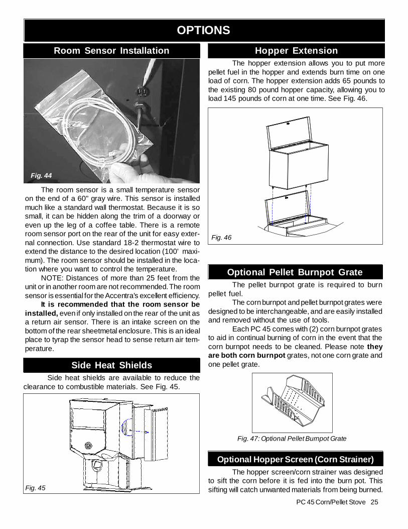
Hopper ExtensionThe hopper extension allows you to put more
pellet fuel in the hopper and extends burn time on oneload of corn. The hopper extension adds 65 pounds tothe existing 80 pound hopper capacity, allowing you toload 145 pounds of corn at one time. See Fig. 46.
Fig. 46
Optional Hopper Screen (Corn Strainer)The hopper screen/corn strainer was designed
to sift the corn before it is fed into the burn pot. Thissifting will catch unwanted materials from being burned.
The room sensor is a small temperature sensoron the end of a 60" gray wire. This sensor is installedmuch like a standard wall thermostat. Because it is sosmall, it can be hidden along the trim of a doorway oreven up the leg of a coffee table. There is a remoteroom sensor port on the rear of the unit for easy exter-nal connection. Use standard 18-2 thermostat wire toextend the distance to the desired location (100' maxi-mum). The room sensor should be installed in the loca-tion where you want to control the temperature.
NOTE: Distances of more than 25 feet from theunit or in another room are not recommended. The roomsensor is essential for the Accentra's excellent efficiency.
It is recommended that the room sensor beinstalled, even if only installed on the rear of the unit asa return air sensor. There is an intake screen on thebottom of the rear sheetmetal enclosure. This is an idealplace to tyrap the sensor head to sense return air tem-perature.
Room Sensor Installation
Fig. 47: Optional Pellet Burnpot Grate
Optional Pellet Burnpot GrateThe pellet burnpot grate is required to burn
pellet fuel.The corn burnpot and pellet burnpot grates were
designed to be interchangeable, and are easily installedand removed without the use of tools.
Each PC 45 comes with (2) corn burnpot gratesto aid in continual burning of corn in the event that thecorn burnpot needs to be cleaned. Please note theyare both corn burnpot grates, not one corn grate andone pellet grate.Side Heat Shields
Side heat shields are available to reduce theclearance to combustible materials. See Fig. 45.
Fig. 45
Fig. 44
26 PC 45 Corn/Pellet Stove
PC 45 Wiring Diagram
27PC 45 Corn/Pellet Stove
Description Part NumberHopper Gasket(6 ft.) 0-88-00248Ash Pan Assembly 1-10-05800Burnpot Housing Weldment 1-10-724103Burnpot Grate Weldment (corn) 1-10-724108Burnpot Front Plate Weldment (corn) 1-10-724107Burnpot Front Plate Lock 2-00-724105Corn Auger Extension 3-00-02676Ceramic Insert Plate 2-00-724104Ceramic Insert 3-20-05238Wiring:
(includes pellet burnpot grate weldment and front plate)
Gold Plated Door Kit 1-00-08520-4Gold Ash Lip Trim with door kitAsh Door Tile Pack(trim & backer plate) 1-00-08618Tile Frame 1-00-08617Tile Pack(1 piece) 3-43-120601(10 choices)
Options:
PC 45 Parts List
Harman Stove Company warrants its products to be free from defects in material or workmanship, in normal useand service, for a period of 6 years from the date of sales invoice and for mechanical and electrical failures, in normal useand service, for a period of 3 years from the date of sales invoice.
If defective in material or workmanship, during the warranty period, Harman Stove Company will, at its option,repair or replace the product as described below.
The warranty above constitutes the entire warranty with respect to Harman Stove Company products. HARMANSTOVE COMPANY MAKES NO OTHER WARRANTY, EXPRESSED OR IMPLIED, INCLUDING “ANY”WARRANTY OF MERCHANTABILITY, OR WARRANTY OF FITNESS FOR A PARTICULAR PURPOSE. Noemployee, agent, dealer, or other person is authorized to give any warranty on behalf of Harman Stove Company. Thiswarranty does not apply if the product has been altered in any way after leaving the factory. Harman Stove Company andits agents assume no liability for “resultant damages of any kind” arising from the use of its products. In addition, themanufacturer and its warranty administrator shall be held free and harmless from liability from damage to property relatedto the operation, proper or improper, of the equipment.
THERE ARE NO WARRANTIES WHICH EXTEND BEYOND THE DESCRIPTION ON THE FACEHEREOF.
THESE WARRANTIES APPLY only if the device is installed and operated as recommended in the user’s manual.THESE WARRANTIES WILL NOT APPLY if abuse, accident, improper installation, negligence, or use beyond
rated capacity causes damage.HOW TO MAKE A CLAIM - Any claim under this warranty should be made to the dealer from whom this
appliance was purchased. Then contact is made with manufacturer, giving the model and serial numbers, the date ofpurchase, your dealer’s name and address, plus a simple explanation of the nature of the defect. Extra costs such asmileage and overtime are not covered. Nuisance calls are not covered by these warranties.
THIS WARRANTY IS LIMITED TO DEFECTIVE PARTS - REPAIR AND/OR REPLACEMENT ATHARMAN STOVE COMPANY’S OPTION AND EXCLUDES ANY INCIDENTAL AND CONSEQUENTIALDAMAGES CONNECTED THEREWITH.
WARRANTY EXCLUSIONS: Failure due, but not limited to, fire, lightning, acts of God, power failures and/orsurges, rust, corrosion and venting problems are not covered. Damage and/or repairs including but not limited to; remotecontrols, filters, fuses, knobs, glass, ceramic brick panels, ceramic fiber afterburners, door packing, tile, ceramic logsets, paint, batteries or battery back-up and related duct work are not covered. Also excluded from this warranty areconsumable or normal wear items including but not limited to; flame guides, grates, coal bars, afterburner hoods, firebrick, gaskets. Additional exclusions for corn stoves are burnpot housing weldment, burnpot grate weldment (pellet orcorn), burnpot front plate (pellet or corn), burnpot front plate lock, corn auger extension, ceramic insert, and ceramicinsert plate. Additional or unusual utility bills incurred due to any malfunction or defect in equipment and the labor cost ofgaining access to or removal of a unit that requires special tools or equipment are not covered. Maintenance needed tokeep the stove in “good operating condition” is not covered. This includes, but is not limited to, cleaning, adjustment ofcustomer controls and customer education. Labor, materials, expenses and/or equipment needed to comply with lawand/or regulations set forth by any governmental agencies are not covered.
This Warranty provides specific legal rights and the consumer may have other rights that vary from state to state.In the event of change in ownership, the remaining portion of this warranty may be transferred to the new owner
by sending the new owner information and a transfer fee of $25.00 US to the Harman Stove Company.PLEASE READ THE LITERATURE BY THE MANUFACTURER FOR THE VARIOUS ACCESSORY
DEVICES. THE MANUFACTURER WARRANTS THESE ACCESSORY DEVICES, NOT HARMAN STOVECOMPANY OR THEIR WARRANTY ADMINISTRATOR. FURTHERMORE, THESE ACCESSORY DEVICESMUST BE INSTALLED AND USED ACCORDING TO THE RECOMMENDATIONS OF THE MANUFAC-TURER.
REMEDIES - The remedies set forth herein are exclusive and the liability of seller with respect to any contract orsale or anything done in connection therewith, whether in Contract, in tort, under any warranty, or otherwise, shall not,except as herein expressly provided, exceed the price of the equipment or part of which such liability is based.
CLARIFY - The above represents the complete warranty, which is given in connection with stoves, manufacturedby Harman Stove Company. No other commitments, verbal or otherwise, shall apply except by a written addendum tothis warranty.
HARMAN GOLD WARRANTY (for corn stove)
6 YEAR TRANSFERABLE LIMITEDWARRANTY (Residential)1 YEAR LIMITED WARRANTY (Commercial)